1
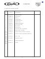
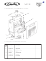
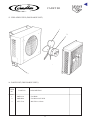
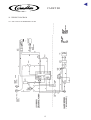
▼
®
PM R22 Issue 3 2/00
CADET SR
▼
CADET SR
®
CONTENTS
1. INTRODUCTION
The Cadet SR is a range of medium capacity soft drinks
soda recirculating coolers. The unit comprises a cooler
producing a nominal 10Kg (22lb) ice bank and a
modular design pump/coil deck which recirculates
carbonated water through the python and cooling coil.
Carbonated water is replenished from the separate
ambient carbonator through a pre-cool coil. The unit
also has 5 syrup cooling coils and a still water coil.
1. INTRODUCTION .................................................. 1
2. SPECIFICATION ................................................... 2
3. INSTALLATION INSTRUCTIONS ..................... 3
3.1 COOLANT RECIRCULATION UNIT ........... 4
3.2 DISCHARGE UNIT ......................................... 4
The unit has been designed with simplicity in mind for
installation, maintenance and operation. All product
connections are situated at one side of the unit to allow
high quality installation work right back to the exit
connections. Maintenance is kept to a minimum with
easy access and replacement of the serviceable items.
4. RECIRCULATION CIRCUIT
OF WATER-COOLED SYSTEM .......................... 5
5. SERVICE INFORMATION
(Faults & Repairs) ................................................... 5
6. USER MAINTENANCE ........................................ 5
7. FAULT FINDING AIR COOLED UNIT .............. 6
8. FAULT FINDING WATER COOLED UNIT ....... 7
9. EXPLODED VIEW (AIR COOLED) .................... 8
10. PARTS LIST (AIR COOLED) ............................... 9
11. EXPLODED VIEW (WATER COOLED) ........... 10
12. PARTS LIST (WATER COOLED) ..................... 11
13. EXPLODED VIEW
(COOLANT RECIRCULATION UNIT) ............. 12
14. PARTS LIST
(COOLANT RECIRCULATION UNIT) ............. 12
15. EXPLODED VIEW (DISCHARGE UNIT) ......... 13
16. PARTS LIST (DISCHARGE UNIT) ................... 13
17. OPERATIONAL SCHEMATICS
17.1 SUBMERSIBLE PUMP ............................... 14
17.2 TOP MOUNTED PUMP .............................. 14
18. WIRING DIAGRAMS
18.1 AIR COOLED SUBMERSIBLE PUMP ...... 15
18.2 WATER COOLED SUBMERSIBLE PUMP 16
18.3 AIR COOLED TOP MOUNTED PUMP ..... 17
18.4 WATER COOLED TOP MOUNTED PUMP 18
19. CRU WIRING DIAGRAM .................................. 19
1
▼
CADET SR
®
2. SPECIFICATION
Air Cooled
DIMENSIONS:
Water Cooled
Submersible
Recirc Pump
Top Mounted
Pump
Submersible
Recirc Pump
Top Mounted
Pump
Height (mm)
392
431
392
431
Width (mm)
645
645
645
645
Depth (mm)
476
476
484
484
Weight dry (kg)
38.3
43.7
37.3
42.8
62.3
67.7
61.6
67.2
Voltage
230/240V, 50Hz
230/240V, 50Hz
230/240V, 50Hz
230/240V, 50Hz
Current Rating
13A fused outlet
13A fused outlet
13A fused outlet
13A fused outlet
4.6A
5A
6.4A
6.7A
operational (kg)
ELECTRICAL
Run Current including carbonator
REFRIGERATION:
Air Cooled
Water Cooled
Compressor (R134a)
15cc
18cc
Condenser Fan
5 Watt motor, 8" fan blade
Nominal Ice Bank (kg)
10
10
3 hours
21/2 hours
Submersible Recirc Pump
Top Mounted Pump
Motor
15 Watt Ext Rotor
4 Pole 80W
Protection
Thermal Cut-Out
Thermal Cut-out
Single stage mag drive
Stainless Steel
Pump Performance
1.0 Litre/min
2.5 Litres/min
Max. Python Length
25m
35m
Soda Pre – cool
9.5mm O.D. x 7.8m
(3/8" O.D. x 25' )
9.5mm O.D. x 11.2m
(3/8" O.D. x 37' )
Soda Recirculation
9.5mm O.D. x 5.7m
(3/8" O.D. x 19')
9.5mm O.D. x 5.7m
(3/8" O.D. x 19')
Still Water Coils
8.0mm O.D. x 2.4m
(5/16" O.D. x 8' )
8.0mm O.D. x 2.4m
(5/16" O.D. x 8' )
5 Syrup Coils
8.0mm O.D. x 1.8m
(5/16" x 6')
8.0mm O.D. x 1.8m
(5/16" x 6')
Typical Pulldown Time
(from 20 Deg C no recirc.)
RECIRCULATION:
Pump
PRODUCT COILS:
Note: All product coils are Grade 316 stainless steel
AGITATION:
Motor
6 W (output) 2 pole shaded pole open construction.
Protection
Internal one shot thermal
fuse. Class ‘F’ insulation
Speed
2400rpm
2
▼
CADET SR
®
– A supply of cold, potable water for still water
dispense, must be available with an accessible means
of isolation. Pressure must be within the range 4 to 6
bar, with a minimum flow of 0.7 litres/min. A boost
pump or pressure regulator may be required to ensure
this.
3. INSTALLATION INSTRUCTIONS
GENERAL DESCRIPTION
The Cadet S.R. is a medium capacity soft drinks soda
recirculating cooler for use with a remote carbonator.
The air cooled and water cooled can be sited remotely,
and the air cooled can also be sited under the counter.
The air cooled unit consists of two assembliesi)
the lid which includes the electrical supply lead
and
(ii) the base which is supplied from the lid by means
of its own plug and lead.
The water cooled unit consists of four assemblies
i)
the lid assembly which includes the electrical
supply lead
ii) the base which is supplied from the lid by means
of its own plug and lead, and provides electrical
and plumbing connections to the cooling system.
iii) Discharge Unit
iv) Coolant Recirculation Unit (CRU)
The water cooled model can be sited in a chilled cellar
with minimal heat output. Heat is dissipated via a water/
glycol mixture to an exterior wall mounted Discharge
Unit. The coolant is pumped via a CRU sited near to the
Cadet SR.
3. For water cooled units only
– The Discharge Unit is designed to operate in the
range of ambient temperatures from -10°C to 32°C. It
should be mounted in a cool, well ventilated position
on a wall and protected from physical damage. The
position of the unit can be a maximum of 30m from
the base unit and access must be provided for pipes
and electrical cable. Secure the unit to the wall in a
manner capable of supporting 9 kg of weight.
– Mount the CRU on a wall above the Cadet SR, and
within 2 metres of the 230 volt outlet socket at the
back of the Cadet SR.
4. Installation
– The appliance must be earthed.
– With the unit unpacked and in position, remove all of
the water and product coil caps.
– Ensure all panels are secured in position.
– At this stage do NOT connect the electrical supply.
– Filling the water bath
Do not use de-ionized water or add any substance to
the water.
Do not leave hose pipes unattended whilst filling the
water bath as the unit may become flooded.
Remove the filler cap and fill the bath with cool,
clean, water until the water flows from the overflow.
HANDLING AND TRANSPORTATION
Keep the cooler and CRU in an upright position and do
not move them after filling.
INSTALLATION
(Air-cooled and Water-Cooled base units)
1. General
Installation must only be carried out by a suitably
trained person and comply with national and local codes
for connection to water and electrical supplies.
It is recommended that the installation is protected by
and RCCB.
5. Python installation
The submersible soda pump (indicated on the main
plumbing label) must never be allowed to run dry, but
the soda recirc tubes may be looped and primed with
potable tap water after which the cooler may be
switched ON to enable the Cadet to build ice whilst
installation work is completed.
– The alternative stainless steel pump can be switched
off by the pump switch sited on the front electrics
panel.
– Connect the python to the dispense head(s), then
disconnect the Cadet from it electrical supply.
– Remove the soda recirc loop.
– Connect all carbonated water, still water and product
lines in accordance with the labelling on the cooler.
– Using the carbonator as a CO2 supply, purge air from
the water recirc lines before turning the water supply
on.
– A wireable plug is provided as an option for
electrical supply from the cooler to the carbonator
and is rated at 230 Volt, 2 Amp.
2. Siting
The cooler is designed for indoor use only, in ambients
between 5°C and 32°C and should not be exposed to
water spillage, spray, steam or high humidity (in excess
of 90% rh)
– Allow 80mm clearance around the unit to aid air
circulation.
– Air vents and louvres should never become
obstructed or blocked, also access should be possible
to the top lid and refrigeration compartment for ease
of service.
– Site the cooler on a firm level support, protect from
physical damage and do not place items on top.
Locate the cooler within 2 metres of an earthed,
switched, 13 Amp, 230 Volt socket which should be
accessible for isolation of the equipment. The socket
should be installed to current IEE regulations.
3
▼
CADET SR
®
6. Additional Instructions for Water Cooled Cadet
SR. with CRU and Discharge Unit
The base unit, CRU, and discharge unit have labelled
connections to aid the assembly of the cooling system.
– Fit the shut – off valves to the coolant flow and
return lines at the rear of the Cadet SR.
The CRU should only be connected to the rear
socket on the Cadet SR. Under no circumstances
should it be adapted for use direct from the mains
supply.
– Fit the shut – off valves to the coolant flow and
return lines on the CRU.
– Fit the shut – off valves to the coolant flow and
return lines on the Discharge Unit.
The Discharge Unit is powered by a 24V supply taken
from the CRU. Using 0.75mm2 twin electrical cable,
connect to the terminals on the Discharge Unit and
CRU.
– Connect the flow and return piping according to the
circuit diagram (do not insulate). Ensure flow and
return lines are not in contact.
All shut – off valves must be in the open position
when installation is complete, prior to start-up.
– On completion of all electrical connections and
plumbing, fill the CRU tank with a 30% glycol/70%
water mix by volume to the indicated level, which is
in the window on the front of the unit, using the
Cornelius glycol supplied with the equipment.
– Switch ON the Cadet unit. With the complete system
running, the CRU liquid level may drop. Top up to
the indicated level if necessary with the correct
glycol mixture. Check for leaks in the coolant system
and rectify if necessary.
The cooling system is now correctly installed.
3.1 COOLANT RECIRCULATION UNIT
(CRU) INSTALLATION INSTRUCTIONS
1. Mount the CRU on a wall above the Cadet SR, and
within 2 metres of the 230 volt outlet socket at the
back of the Cadet SR.
2. Fit the shut-off valves (supplied) to the coolant flow
and return lines on the CRU.
Note: Ensure that valves are in the open position
when installation is complete, prior to start-up.
3. Connect CRU power supply lead to the outlet
socket at the rear of the Cadet SR.
Note: The CRU should only be connected to the
Cadet SR. Under no circumstances should it be
adapted for use direct from mains supply.
Connect flow and return piping according to the
circuit diagram (do not insulate). Ensure flow and
return lines are not in contact.
4. Fill the tank with the 30/70% glycol/water mix to
the indicated level. When the complete system is
installed and running, the liquid level may drop. On
the completion of electrical connections and
plumbing, top up to the indicated level again, if
necessary.
3.2 DISCHARGE UNIT
INSTALLATION INSTRUCTIONS
1. Mount the Discharge Unit in the required remote
position, and provide access for pipes and cables to
the CRU (maximum 30 metres from the CRU).
2. Fit the shut-off valves (supplied) to the coolant flow
and return lines on the Discharge Unit.
Note: Ensure that valves are in the open position
when installation is complete, prior to start-up.
3. The discharge unit is powered by a 24V supply
taken from the CRU. Using 0.75mm2 twin electrical
cable, connect to the terminals on the Discharge
Unit to the CRU.
4. Connect flow and return piping according to the
circuit diagram (do not insulate). Ensure flow and
return lines are not in contact.
The unit is now ready to run, when the Cadet SR
and the CRU are correctly installed.
7. Priming the python
– Once the dispense system is fully connected, proceed
to prime the soda recirc lines.
– Open a dispense valve until carbonated water is seen.
– Draw 4.5 litres (8 pints) of carbonated water, 0.285
litre (1/2 pint) at a time, with 5 second intervals.
4
▼
CADET SR
®
and removing the securing screws from the pump
plate (to gain access to these screws the motor
capacitor may require moving). When the motor is
exchanged, hole positions and other supplies exist for
alternatives.
Pumps can only be removed after the soda recirc system
has been bled and depressurized. Once a pump is
changed prime the system as illustrated in ‘Priming the
Python’
4. RECIRCULATION CIRCUIT OF WATER
COOLED SYSTEM
OUTLET
DISCHARGE
COOLER
INLET
Additional Maintenance for Water Cooled Units.
Ensure grilles and condenser fins on the Discharge
Cooler remain unobstructed and free from particles at
all times to ensure reliable and consistent operation.
Check the Discharge Cooler fan is working. This is
controlled by a thermostat in the CRU and will operate
when the coolant mix rises above 15°C – 20°C.
Check the coolant pipework for damage/leads and
rectify if necessary.
Check the level of coolant in the CRU and refill if
necessary, with a 30% Glycol/70% Water mix.
Refer to separate maintenance manual for further
information.
INLET
OUTLET
COOLANT
RECIRC.
UNIT
OUTLET
WATER COOLED CADET
INLET
6. USER MAINTENANCE
Switch off and unplug the unit during maintenance
operations.
Do not attempt to remove any protective covers.
Ensure grilles and condenser fins remain unobstructed
and free from particles at all times to ensure reliable and
consistent operation. A soft brush or vacuum cleaner
may be used for cleaning.
Sanitizing the pipelines – flush with water, followed by
a chlorinated alkaline sanitizing agent and finally
potable water flush when tainting is evident or when
advised by the equipment installer or beverage supplier.
It is important that the sanitizing agent
manufacturer’s procedure and safety precautions
are followed.
Ensure that objects are not placed on top of the unit as
this may affect the units function.
The 1989 Electricity at Work Regulations require
periodic testing of electrical equipment and this should
only be carried out by a competent person.
5. SERVICE INFORMATION
(faults/repairs)
There are no user serviceable items inside the
equipment. Maintenance and repairs must only be
carried out by a properly qualified and trained person.
Switch off the mains electrical supply and unplug the
equipment if it malfunctions or suffers spillage or
physical damage.
In the event of component failure, SWITCH OFF AND
UNPLUG the unit.
Access to:– The compressor electrics, thermostat and condenser
fan can be made by removing the fan door assembly
which is retained by a single screw and lift off
hinges.
– The submersible soda recirculation pump motor and
separate agitator is by removing the pump cover. The
pump motor can be removed by disconnecting
electrical connections, undoing the locking screws on
the pump plate and twisting the assembly clockwise
to enable the motor to be lifted clear.
– The alternative top mounted pump assembly motor is
by removing the agitator and electrics cover,
disconnecting all electrical connections to the motor
5
▼
CADET SR
®
7. FAULT FINDING AIR COOLED UNIT
WARM
DRINKS
Y
NO DRINKS
SYRUP ONLY
DISPENSED
Is there
an ice bank?
Is ice bank
oversize?
N
Is the compressor
and fan running?
N
Replace ice bank
thermostat.
Y
Probable ice bank
thermostat failure,
check and replace
as necessary. Allow
sufficient time for
coil thaw.
Y
Probable fault in
dispense valves,
replace as
necessary.
N
Y
Is the compressor
and fan running?
N
Refrigeration fault.
Replace cooler.
Is there soda supply
from carbonator?
Y
Is the ice bank
recovering?
N
Refrigeration fault.
Replace cooler.
N
Y
Is the pump/
agitator motors
running?
N
Check fuses and
replace as
necessary.
N
Check supply and
replace motors if
necessary.
See carbonator
product manual for
specification.
Y
Is the pump/
agitator motors
running?
Y
Is the recirc flow
evident?
Y
N
Check circuit is
purged of CO2 gas
check pump
operation
Correct any
Installation or
ambient
temperature
problems
6
▼
CADET SR
®
8. FAULT FINDING WATER COOLED UNIT
❖
Fault finding is very similar to the air cooled model.
❖
Follow the air cooled table on the previous page, with the additions detailed below.
Problem
Possible Fault
Possible Cause
Action
Product
consistently too
warm.
No ice bank or water
bath too warm.
No coolant in CRU.
Refill with 30% Glycol 70%
water. Check for leaks.
Coolant pump in CRU
failed.
Replace.
Coolant not flowing
through Discharge Cooler.
Check all the stop valves are
open.
Discharge Cooler airflow
blocked.
Clear blockage. Clean fins as
necessary.
Discharge Cooler fan
failed.
Replace.
Damaged coolant recirc
pipes
Repair.
Discharge Cooler airflow
blocked.
Clear blockage. Clear fins as
necessary.
Discharge Cooler fan
failed.
Replace.
Product too
warm after a
period of time.
Insufficient ice or slow
ice build.
7
▼
CADET SR
®
9. EXPLODED VIEW (AIR COOLED)
1
2
12
3
11
10
9
4
8
7
5
6
8
▼
CADET SR
®
10. PARTS LIST (AIR COOLED)
ITEM
No.
PART No.
DESCRIPTION
1.
99 1100 003
Submersible Pump Assembly
2.
99 2ZU702A
Agitator Assembly
3.
03 IMR0 99A
Agitator Motor
4.
58 0475 170
Filler Cap
5.
99 1104 005
Overflow Outlet
6.
99 1100 152
Fan Door Assembly
7.
58 1174 007
Ice Bank Thermostat
8.
44 0000 208
44 0000 233
Compressor Set (Danfoss Compressor)
Compressor Set (Electrolux Compressor)
9.
58 0446 138
240V Auxilliary Plug
10.
58 0440 346
Fuse 1.5 Amp
11.
58 0440 408
Rocker Switch
12.
99 1104 003
Pump Start Capacitor
Not
Shown
99 0420 089
Compressor Relay (for Danfoss Compressor)
Not
Shown
99 0420 175
Compressor Relay (for Electrolux Compressor)
Not
Shown
58 0420 193
99 0420 174
Compressor Capacitor (for Danfoss Compressor)
Compressor Capacitor (for Electrolux Compressor)
Not
Shown
58 0440 334
Mains Indicator
Not
Shown
58 0420 562
Pump – Rotoflow
Not
Shown
99 2874 305
Pump Motor (80w) Top Mounted
Not
Shown
99 2870 312
Carbonator Mounting Kit
9
▼
CADET SR
®
11. EXPLODED VIEW (WATER COOLED)
12
1
2
11
10
9
8
3
7
6
5
4
10
▼
CADET SR
®
12. PARTS LIST (WATER COOLED)
ITEM
No.
PART No.
DESCRIPTION
1.
99 2ZU702A
Agitator Assembly
2.
03 IMR0 99A
Agitator Motor
3.
58 0475 170
Filler Cap
4.
99 1104 005
Overflow Outlet
5.
58 1174 007
Ice Bank Thermostat
6.
44 0000 209
Compressor Set
7.
58 0440 401
Thermal Cut-Out Switch
8.
58 0446 138
240V Auxilliary Plug
9.
58 0440 408
Rocker Switch
10.
58 0440 334
Mains Indicator
11.
99 2874 305
Pump Motor (80w) - Top Mounted
12.
58 0420 562
Pump Assembly - Rotoflow
Not
Shown
99 0420 089
Compressor Relay (for Danfoss Compressor)
Not
Shown
58 0420 193
Compressor Capacitor (for Danfoss Compressor)
Not
Shown
58 0440 346
Fuse 1.5 Amp
Not
Shown
99 1104 003
Pump Start Capacitor
Not
Shown
99 2870 312
Carbonator Mounting Kit
Not
Shown
99 1100 132
Foot Kit
11
▼
CADET SR
®
13. EXPLODED VIEW (COOLANT RECIRCULATION UNIT)
1
2
6
3
5
4
14. PARTS LIST (COOLANT RECIRCULATION UNIT))
ITEM
No.
PART No.
DESCRIPTION
1.
58 2875 403
Tank Header
2.
2ZU573A
Ball Valves 15mm
3.
99 2874 401
Pump
4.
2ER208A
Transformer 24V
5.
58 0400 075
Thermostat
6.
58 0475 060
Control Knob
12
▼
CADET SR
®
15. EXPLODED VIEW (DISCHARGE UNIT)
1
2
3
16. PARTS LIST (DISCHARGE UNIT))
ITEM
No.
PART No.
DESCRIPTION
1.
2MP161A
Fan Blade
2.
2MR400A
Fan Motor 24V 50Hz
3.
2ZU 573A
Ball Valves 15mm
13
▼
CADET SR
®
17. OPERATIONAL SCHEMATIC
DISPENSE HEAD
17.1 SUBMERSIBLE PUMP
CO2 SUPPLY
MAINS
WATER
SUPPLY
AMBIENT
CARBONATOR
I
C
E
I
C
E
SODA
PRE-CHILL
COIL
SODA RECIRC
COOLING COIL
SUBMERSIBLE
PUMP
17.2 TOP MOUNTED PUMP
CO2 SUPPLY
MAINS
WATER
SUPPLY
DISPENSE HEAD
AMBIENT
CARBONATOR
I
C
E
I
C
E
SODA
COOLING COILS
14
▼
CADET SR
®
18. WIRING DIAGRAM
18.1 AIR COOLED SUBMERSIBLE PUMP
15
▼
CADET SR
®
18.2 WATER COOLED SUBMERSIBLE PUMP
16
▼
CADET SR
®
18.3 AIR COOLED TOP MOUNTED PUMP
17
▼
CADET SR
®
18.4 WATER COOLED TOP MOUNTED PUMP
18
▼
CADET SR
®
19. CRU WIRING DIAGRAM
Fuse
5 Amp
L
N
Pump
Assembly
Grn/Yel
Grn/Yel
Grn/Yel
Red
Blue
Thermostat
Main
Earth
Mains in
240V 50Hz
from Base
Unit
Remote
Discharge
Fan
L
N
27.4v
0v
Transformer
Grn/Yel
Brown
Blue
Red
Red
Fuse
5 Amp
19
▼
ORDER FORM/
PROFORMA INVOICE
®
Please complete fully all parts 1-4
OFFICE USE ONLY
Cornelius Account No.
Customer Order Number:
Name: --------------------------------------------------------------- Company Name: ---------------------------------------------------------Day Time Phone Number: ---------------------------------------- Fax Number: --------------------------------------------------------------Invoice Address: --------------------------------------------------
Delivery Address: -------------------------------------------------
-----------------------------------------------------------------------
-----------------------------------------------------------------------
---------------------------------------- Post Code: -----------------
---------------------------------------- Post Code: -----------------
Special Instructions: ------------------------------------------------------------------------------------------------------------------------------OFFICE USE ONLY
Part Number
Qty Required Price per Unit
Part Description
Total Cost
OFFICE USE ONLY
Acknowledgement No.
Cheque Clearance Date
Cost
Due Date
Delivery
Request Date
VAT @ 17.5%
Total Order Value
IMI Cornelius standard terms & conditions of sale apply.
Please indicate payment method:
Account
Cheque
Postal Order
Access/Visa
Cheques or Postal Orders should be made payable to IMI Cornelius (UK) Ltd.
For
Access or
Visa Payments, please indicate your card number.
Expiry Date: --------------------------Signature: ------------------------------------------------ Name: -------------------------------------------------- Date: -------------------Address: -------------------------------------------------------------------------------------------------------------------------------------------------------------------------------------------------------------------------------------------- Post Code: -----------------------------------Please return to: IMI CORNELIUS (UK) LTD Rawson Spring Way Riverdale Industrial Estate Sheffield S6 1PG
TEL: 0114 285 5886
ORDER
8.30 am
☎
HOTLINE
5.15 pm
FAX: 0114 232 1070
▼
®
IMI CORNELIUS (UK) LTD
®
Tything Road
Alcester
Warwickshire
England B49 6EU
Telephone: 01789 763101
Facsimile: 01789 400595