1
FK1376 A YS0108
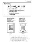
AC-10S, AC-10F
Access Control
Clavier à Codes rétro-éclairé
Türcodemodul
Control de acceso
Codeklavier
Surface mount type
Clavier saillie
Aufputztyp
Montaje en superficie
Opbouwmontage
AC-10S
Flush mount type
Clavier encastré
Unterputztyp
Montaje empotrado
Inbouwmontage
AC-10F
INSTALLATION & OPERATION MANUAL
NOTICE D'INSTALLATION ET D'UTILISATION
INSTALLATIONS- UND BEDIENUNGSANLEITUNG
MANUAL DE INSTALACIÓN Y USO
INSTALLATIE & GEBRUIKSHANDLEIDING
RECORD OF SETTINGS AND REGISTRATION DETAILS (Please make sure to write down your settings below.)
AIDE MEMOIRE DES PROGRAMMATIONS ENREGISTREES (Faire en sorte de bien noter vos réglages ci-dessous.)
VERZEICHNIS DER EINSTELLUNGEN UND REGISTRIERUNGSDETAILS (Bitte notieren Sie unten Ihre Einstellungen.)
DATOS DE CONFIGURACIÓN Y DETALLES DE LOS REGISTROS (Asegúrese de apuntar los valores de ajuste abajo.)
LIJST MET GEPROGRAMMEERDE INSTELLINGEN EN CODES (Zorg ervoor uw instellingen hieronder op te schrijven.)
Master code
Code maître
Mastercode
Código maestro
Hoofdcode
Key illumination time
Temporisation d'éclairage
Tastenbeleuchtungszeit
Tiempo de encendido de las teclas
Verlichtingsduur klavier
Relay output time
Temporisation des relais
Relais Ausgabezeit
Tiempo de salida Relé
Relais outputtijd
sec/sek/seg
Relay 1
Relais 1
Relais 1
Relé 1
Relais 1
Relay 2
Relais 2
Relais 2
Relé 2
Relais 2
sec/sek/seg
sec/sek/seg
External output setting
Paramétrage de sortie externe
Externer Ausgang
Ajuste de la salida externa
Activering Alarmuitgang
Lockout
Blocage
Eingabe-Sperre
Bloqueo
Blokkering klavier
Auto-relock
Auto-reverrouillage
Automatische Neuverriegelung
Re-bloqueo automático
Automatische hersluiting
Timer-linked unlocking
Déverrouillage lié à l'horloge
Timergesteuerte Entriegelung
Desbloqueo conectado al temporizador
Tijdsgebonden ontgrendeling
Operation tone
Bip de fonctionnement
Signaltöne
Tono de operación
Zoemer klavier
ON
EIN
AAN
OFF
AUS
UIT
ON
EIN
AAN
OFF
AUS
UIT
ON
EIN
AAN
OFF
AUS
UIT
1
ON
EIN
AAN
2
1&2
OFF
AUS
UIT
Registered User Code List / Liste des codes utilisateur programmés / Liste der registrierten Zugangscodes
Lista de códigos de los usuarios registrados / Lijst Codes Geregistreerde Gebruikers
group 1 / groupe 1 / gruppe 1 / grupo 1 / groep 1
group 2 / groupe 2 / gruppe 2 / grupo 2 / groep 2
00
30
60
90
01
31
61
91
02
32
62
92
03
33
63
93
04
34
64
94
05
35
65
95
06
36
66
96
07
37
67
97
08
38
68
98
09
39
69
99
10
40
70
11
41
71
12
42
72
13
43
73
14
44
74
15
45
75
16
46
76
17
47
77
18
48
78
19
49
79
20
50
80
21
51
81
22
52
82
23
53
83
24
54
84
25
55
85
26
56
86
27
57
87
28
58
88
29
59
89
1
English
PRECAUTIONS
General Prohibitions
Prohibition to Dismantle the Unit
English
General Precautions
3. Before turning on power, make sure wires are not
crossed or shorted. Fire or electric shock could result.
WARNING
(Negligence could result in death or serious injury to
1. When mounting the unit on a wall, install the unit in a
convenient location, but not where it could be jarred or
bumped. Injury could result.
2. Do not install or make any wire terminations while
power supply is plugged in. It can cause electrical
shock or damage to the unit.
CONTENTS
RECORD OF SETTINGS AND REGISTRATION DETAILS … 1
PRECAUTIONS …………………………………………… 2
FUNCTIONS SETTING UP ……………………………… 5
OPERATIONS ……………………………………………… 9
PACKAGE CONTENTS …………………………………… 2
NAMES ……………………………………………………… 3
MOUNTING ………………………………………………… 3
TECHNICAL PRECAUTIONS …………………………… 9
SPECIFICATIONS ………………………………………… 9
WARRANTY ………………………………………………… 9
MOUNTING/WIRING METHOD, WIRING DISTANCE …… 4
TEMPLATE FOR AC-10S MOUNTING BRACKET (SCALE 1:1) … 42
PACKAGE CONTENTS
AC-10S
Unit
Mounting
bracket
Mounting
screws
AC-10F
Special
Operation
screwdriver
manual
Unit
Flush mount Special
Operation
back box screwdriver manual
2
Nederlands
(Negligence could result in injury to people or damage
to property)
1. This product, being a control unit of door release,
should not be used as a crime-prevention device.
2. This product is weather-resistant, but do not spray
high-pressure water on it. Unit trouble could result.
3. The product becomes inoperative during power failure.
4. As to other manufacturer's devices, such as sensor,
door releases, timer, used with this system, comply
with the Specifications and Warranty conditions
manufacturers or venders present.
Español
CAUTION
GENERAL PRECAUTIONS
Deutsch
1. Do not connect any non-specified power source to the
V, V terminals, and do not install two power supplies in
parallel to a single input. Fire, damage to the unit, or
system malfunction could result.
2. The unit is not explosion-proof. Do not install or use
near gases or flammable materials. Fire or explosion
could result.
3. Do not dismantle or alter the unit. Fire or electric shock
could result.
4. Do not allow the wires or DC output terminals to be
shorted. Fire or electric shock could result.
Français
people)
4. Do not install the unit in any of the following locations.
Fire, electric shock, or unit trouble could result.
* Places subject to dust, oil, chemicals, hydrogen sulfide
(hot spring).
* Places subject to moisture and humidity extremes,
such as bathroom, cellar, greenhouse, etc.
* Places where the temperature is quite low, such as
inside a refrigerated area or in front of air-conditioner.
* Places subject to steam or smoke (near heating or
cooking surfaces).
* Where noise generating devices such as dimmer
switches, invertor electrical appliances, are closeby.
NAMES
2
4
English
1
1
2
3
Français
3
1 LED indicator (Orange)
2 LED indicator (Green)
3 Keys (Yellow)
4 Special screws for panel mounting
4
MOUNTING
AC-10S
AC-10F
1. Drill holes in the wall to match the size and number of screws.
1. Detach the AC-10F panel using the special screwdriver
supplied.
2. Attach the mounting bracket to the wall using the
mounting screws.
2. Attach the flush mount back box to the wall.
3. Attach the unit to the mounting bracket using the special
3. Attach the panel to the flush mount back box using the special
screwdriver and the special screws for panel mounting.
AC-10S
AC-10F
85mm (3-3/8")
55mm (2-3/16")
Cable
100mm
(3-15/16")
1
45mm
(1-12/16")
Wall
Spare screw holes
3
Click
2
Flush mount back box
When this unit is to be used with the JF-DV, please refer to the illustration below when installing it.
Please also refer to "TEMPLATE FOR AC-10S MOUNTING BRACKET(SCALE 1:1)"(page 42).
2. Positions for drilling holes
3. Position of mounting bracket
Please refer to the
Refer to the illustration
below when attaching the
illustration below when
mounting bracket.
drilling the holes. Make
sure the cable inlet is within
the shaded area shown in
the illustration below.
98mm (3-7/8")
42.5mm
(1-2/3")
3.5mm
(1/8")
49mm
(1-15/16")
3
49mm
(1-15/16")
A hole for cable inlet
15mm (9/16")
49mm (1-15/16")
55mm
(2-3/16")
98mm (3-7/8")
64mm (2-1/2")
「Cable inlet」
4. Installation
Attach the unit to the mounting bracket
by pushing it into the bracket. Tighten
the screws to complete the installation.
( ) As there are drain holes at the bottom
of the JF-DV unit, do not block the space
between the JF-DV and the access control
keypad.
5mm
(3/16")
1. JF-DV unit
173mm (6-13/16")
Nederlands
screwdriver and the special screw for mounting.
11.5mm (7/16")
55mm
(2-3/16") 42.5mm (1-2/3")
68.5mm (2-11/16")
Español
Deutsch
4
(※)
MOUNTING/WIRING METHOD, WIRING DISTANCE
A
(Wiring distance)
Power supply
Power supply
AC/DC12 ~ 18V
Relay
A
2
2
2
Request to exit/entry
button
2
Timer
C
Español
Terminal names
Back view of AC-10S
User group1 relay 1
Request to Request to
exit/entry exit/entry Common
button 1
button 2
Power supply
V
PB1
N/C contact
Timer
C
PB2
User group2 relay 2
N/C contact
T
NO1
NC1
C1
N/O contact
C2
NO2
NC2
Nederlands
V
N/O contact
Power supply
Request to exit/entry button・Timer
Relay
Between 12 and 24V AC
Between 12 and 24V DC
・Minimum overload :100mV DC, 0.1mA or above
・Contact capacity: 3V DC, 0.1A or above
24V DC, 3A (resistive load) 1A (inductive load)
24V AC, 3A (resistive load) 1A (inductive load)
・Minimum overload :5V DC, 100mA or above
Connection of Relay 1 only
Example of electric door
strike connection (N/O)
V
V
PB1
PB2
C
T
NO1
C1
NC1
NO2
C2
Example of automatic
gate connection (N/O)
NC2
NO1
C1
NC1
Example of electromagnetic door
lock connection (N/C)
N
NO1
C1
NC1
NP
2
2
NO2
C2
Electromagnetic
door lock
Electric door strike
2
2
NP
2
NP
or
NP
or
NP
PS
Automatic gate
Power supply
Request to exit/entry button
(push button, etc.)
Power supply
AC transformer
Relay 1: Automatic gate (N/O contact), Relay 2: Electric door strike (N/O contact)
V
V
2
PB1
PB2
C
T
NO1
For relay 1
Request to
exit/entry button
C1
NC1
NO2
C2
NC2
External output
NP
2
Power supply
Rating
Between 12 and 24V AC
Between 12 and 24V DC
2
NP
NP
NO2
C2
Only connecting to the terminal
of relay 2 is possible.
Alarm, Security
Electric door strike
2
Automatic gate
NP
For relay 2
Request to
exit/entry button
AC transformer
2
Auto-relock/External out put by forced entry
(sensor connection is required)
NP
N.C
Timer
2
NP
PB2
Deutsch
Electric
door strike
D
Français
Electromagnetic
door lock
Request to exit/entry
button
2
Relay
or
AC/DC18 ~ 24V
300m (980')
300m (980')
300m (980')
The connection distance will depend on
the specifications of the electric door strike,
relays or Electromagnetic door lock to be
connected. To determine the operating range,
please refer to the specifications of each
terminal.
B
C
B
100m (330')
(Less than)
2
Automatic gate
diameter 0.65 - 1.0 mm (22-18AWG)
English
D
・To setVJG "auto-relock" / "External output by forced entry" function a
sensor (locally avallable) is required.
C
・The request to exit/entry button for relay 2 cannot be used when the
"auto-relock" / "External out put by forced entry" function are set.
4
Deutsch
Français
English
FUNCTIONS SETTING UP
This section explains the settings of each function, including the master code for management, the user code for unlocking, the
buzzer and the LEDs.
About the setting mode:
Enter master code twice to switch to the setting mode, and enter the following setting code to perform the settings
for the desired function. After settings have been made, enter the following setting codes to continue the setting
to exit the setting mode.
operation. Press
Setting items
Setting the code length
Allowable setting range
4, 5, or 6 digits
Default value
4 digits
1
Valid keys: 0 - 9, A, B
1234
Number of codes: 60
Valid keys: 0 - 9, A, B
-
-
Number of codes: 40
Valid keys: 0 - 9, A, B
-
-
Illumination time: 10 to 99
seconds, or continually lit
10 Sec.
Output time: 1 to 99
seconds, or latched
3 Sec.
Output time: 1 to 99
seconds, or latched
3 Sec.
Set the output time of relay 2.
Reset Settings
-
-
· OFF
· During Lockout
· During forced entry output
· During lockout and forced
entry output
OFF
ON/OFF
Invalid number of times:
10 to 99 times
Invalid time:
10 to 99 seconds
OFF
ON/OFF
OFF
Linked relay: relay 1
relay 2
relay 1 and 2
Linked relay: relay 1
Change the length of the master code and the user code.
)They both must be the same length.
Setting the master code
Enter a master code using between 4 and 6 digits (alpha or numeric) to
switch to the setting mode.
) The number of digits in the code can be set by setting the code length.
Setting the code for user group 1
Set the unlocking code for user group 1.
) The number of digits in the code can be set by setting the code length.
Español
Setting the code for user group 2
Set the unlocking code for user group 2.
) The number of digits in the code can be set by setting the code length.
Setting the key illumination time
Set the length of time that the keys will be lit up after they are pressed.
Setting the relay 1 output time
Nederlands
Setting code
Set the output time of relay 1.
Setting the relay 2 output time
Return all the settings to their default values.
External output setting
The alarm or security system connected to the terminal of relay 2 will be
activated when the "Lockout" * or the forced entry* is carried out.
* "Lockout": Refer to VIII below. *Forced entry: This function is linked with
the door open/close sensor (N.C.) which is connected to PB2 and C, and
carried out when opening the door without activating this unit. (For example,
entry in an improper manner, manual unlock, etc.)
) If there is a way to open the door without activating this unit, such as
manual unlock, do not make the external output setting for the forced entry.
Lockout
If several incorrect access codes are attempted, the code input function is
disabled for a programmed period of time.
· When "Lockout" is activated, the LED (Orange) indicator and the keypad
blink, and the buzzer sounds for 3 seconds. This is just a sound to inform
you that the function has been activated. It is not a warning sound. If you
want a warning to be sounded, please use the external output function to
activate a commercially-available alarm device.
· The unlock function will work when the request to exit/entry button is
pushed, even while the "Lockout" function is operating.
Auto-relock (Anti-tailgate)
After the door has been linked to the door open/close sensor (N/C), and
unlocked, it will relock itself one second after being closed, thus preventing
the entry of an unauthorized third party. )1
Timer-linked unlocking setting
The system can be set to unlock the door by pressing the
key within
the set time and linking it to the external timer (N/O). The operations for the
LEDs and the buzzer after unlocking are the same as those used to perform
user code unlocking. When the door is linked to the timer, unlocking can be
performed using the user code and the request to exit/entry button. When
latch output is performed for the relay settings, the relay turns ON/OFF
key is pressed.
every time the
Operation tone settings
0 key illumination: OFF
0 key illumination: ON/OFF
ON/OFF
ON
Set the tone heard when the keypad is being used to ON/OFF.
• The setting can be saved even when the power is off.
• The system cannot be switched to the setting mode while the relay is unlocked.
• When the setting mode has been activated and no operations are performed for approximately 120 seconds, the system
will exit the setting mode. (If a key is pressed during that time, the timer will start over.)
• Neither the request to exit/entry button nor the timer-linked unlocking
key can be operated, and unlocking using the
user code cannot be performed while the setting mode is activated.
• The volume (the check tone, operation tone, etc.) from the main unit may become lower according to the mounting status.
1 : When the auto-relock is used, the request to exit/entry button for relay 2 cannot be used. The output of relay 2 is
5
only possible when user code unlocking is performed.
Orange (L)
The result of each operation is indicated by the
Green (R)
lighting up of the LED indicators on the upper section
(orange) (green)
Illumination Blinking
Input the master code twice.
)
Setting the master code
(Default㧦1234)
Setting the code
group 1
00 - 59
60 - 99
Input the setting code.
Inputting of user number (ex.: 01)
Inputting of user number (ex.: 60)
When a user code
that has already
been set is selected
When a user code
that has already
been set is selected
Blinks
Illumination Blinking Illumination twice
Blinks
Illumination Blinking Illumination twice
Bleep
Bleep
Bleep
Inputting of code length (ex.: 5 digits)
4, 5, or 6 digits
Illumination Blinking
Illumination Blinking
Beep
- When the
(If the
Inputting of new master code
(ex.: 4321)
Bleep,
Bleep
Inputting of code (ex.: 1006)
* Numbers 0 - 9 and the
letters A and B can be used
Inputting of code (ex.: 04B2)
* Numbers 0 - 9 and the
letters A and B can be used
Illumination Blinking
Illumination Blinking
Beep
Beep
key is pressed, the green LED lights up, the buzzer beeps twice, and the system exits the setting mode.
key is included in the user code and the master code, the system does not exit the setting mode.)
- You can continue the setting up operation by entering an arbitrary setting code.
· The set code will be saved in
memory, even if the code length
is changed. However, codes of
different lengths cannot be used.
· When the code length has been
changed, the master code returns
to the default value (if the number
of digits in the code is 4, 5, or 6,
the master code is 1234, 12345,
or 123456 respectively).
· Please note that the shift to the
setting mode can be performed
during timer-linked unlocking.
However, if "
" is included in
the master code, the door will
be unlocked, and the shift to
the setting mode will not be
able to be performed.
· The same code cannot be set
for both the user code and the
master code (the previously set
code has priority).
· Do not set simple codes, such
as 1111.
· We recommend that you
change the default master
code.
Bleep,
Bleep
Bleep
Beep
Indicator
goes out
Blinking
Bleep,
Bleep
· To make the set user code invalid, press 0000 (when 4 digits are
used), 00000 (when 5 digits are used), or 000000 (when 6 digits are
used). Code numbers which contain only "0" cannot be set as user
codes.
· As the factory pre-setting master code is 1234, 1234 (when 4 digits
are used), 12345 (when 5 digits are used), and 123456 (when 6
digits are used) cannot be set as user codes.
· Do not set simple codes, such as 1111.
* The same code cannot be set for both the user code and the
master code. The previously set code has priority.
6
Nederlands
Illumination Blinking
Illumination Blinking
group 2
Español
Input the setting code.
Bleep, Bleep
Deutsch
Setting the code length
(Default: 4 digits)
Français
(Default:
English
of the unit, and by the sounding of the buzzer.
(orange) (green)
Illumination Blinking
Input the master code twice.
English
(Default :
Français
Setting the key illumination time
(Default: 10 Sec.)
Setting the relay output time
(Default: 3 Sec.)
When setting relay 1
Input the setting code.
Deutsch
Bleep, Bleep
)
Illumination Blinking
Reset Settings
When setting relay 2
Input the setting code. Input the setting code.
Illumination Blinking
Bleep
Input the setting code.
Illumination Blinking
Bleep
Input the setting code.
Illumination Blinking
Bleep
Español
Nederlands
External output setting
(Default: OFF)
Bleep
During
Lockout
Inputting of illumination time
(ex.: 20 seconds)
Inputting of relay output time
(ex.: 99 seconds)
10 - 99
Indicator is lit up at all times: 00
01 - 99
Latched (̪) : 00
Illumination Blinking
Beep
- When the
(If the
Illumination
Illumination Blinking
Blinks three times
- You can continue the setting up operation by entering an arbitrary setting code.
7
Beep
key is pressed, the green LED lights up, the buzzer beeps twice, and the system exits the setting mode.
key is included in the user code and the master code, the system does not exit the setting mode.)
· If the power is turned off and
the
,
, and
keys are
pressed simultaneously while the
unlock 1 input status is active
(short circuit between terminals
PB1 and C), the settings can be
returned to their default values by
turning the power back on and
pressing the
,
, and
keys simultaneously for 3
seconds.
OFF
Illumination Blinking
Bleep, Bleep, Beep
Beep
· (̪) If the latched status has
been set and the door is
unlocked, it will not be locked
again until the user code is
entered (or the request to
exit/entry button is pressed, or
the
key is pressed while
timer-linked unlocking is set).
· When the door is unlocked
during relay outputting
(including when latched), the
system cannot be switched to
the setting mode.
During lockout
During forced and forced
entry output entry output
Indicator
goes out
Blinking
Bleep,
Bleep
· When setting the external output,
do not set the relay 2 output to be
latched.
(orange) (green)
Illumination Blinking
Input the master code twice.
(Default :
Bleep, Bleep
)
Illumination Blinking
Bleep
OFF
ON
Input the setting code.
Input the setting code.
Illumination Blinking
Bleep
OFF
ON
Illumination Blinking
Bleep
Bleep
Relays 1 and 2
are both linked
Only relay 1
is linked
Only relay 2
is linked
Deutsch
Illumination Blinking
Input the setting code.
Operation sound settings
(Default: ON)
Français
Input the setting code.
Timer-linked unlocking setting
(Default: relay 1, OFF)
English
Auto-relock
(Anti-tailgate)
(Default: OFF)
Lockout
(Default: OFF)
Operation
tone OFF
Operation
tone ON
Español
Illumination Blinking
Illumination Blinking
Illumination Blinking
Illumination Blinking
Nederlands
Beep
Beep
Illumination Blinking
Beep
Bleep
Bleep
0 key illumination OFF 0 key illumination ON
while timer is on
while timer is on
Inputting the number of operations
(ex.㧦10 times)
10 -99
Illumination Blinking
Illumination Blinking
Bleep
Beep
Inputting length of time in "Lockout" mode
(Ex.: 10 seconds)
10 - 99
Illumination Blinking
Beep
- When the
(If the
key is pressed, the green LED lights up, the buzzer beeps twice, and the system exits the setting mode.
key is included in the user code and the master code, the system does not exit the setting mode.)
- You can continue the setting up operation by entering an arbitrary setting code.
· When the relay 1 output time is
set to latched output, the
auto-relock function is
disabled.
· When the auto-relock function
is turned on, the unlock
function of the request to
exit/entry button of relay 2 is
disabled.
Indicator
goes out
Blinking
Bleep,
Bleep
· If the 0 key illumination function
is turned on while the timer is
on, only the 0 key illumination
will light up, even if the "key
illumination time setting" is set
to "Indicator is continually lit".
8
Français
English
OPERATIONS
A. Unlocking of user code
When the registered user code has been input using the
keypad (between 4 and 6 digits), the LED indicator (group
1: orange, group 2: green) lights up, the buzzer sounds,
and the electric door strike is unlocked.
ex.): group 1
group 2
1006
04B2
Orange LED lights up (during relay1 operation)
Green LED lights up (during relay2 operation)
Nederlands
Español
Deutsch
Beep
Beep
• The time interval during which the button must be
pressed is approximately 10 seconds. If the time
interval exceeds approximately 10 seconds, the input
value will be cleared.
• If you make a mistake when inputting the user code,
input the user code again.
• When the "Lockout" function has been set, the release
function is locked and the input operation is disabled for
the specified time (10 ~ 99 seconds) if invalid codes are
input a set number of times (10 ~ 99 times). (Reference:
"Lockout".) During this time, the key illumination will
blink 4 times, the LED (orange) indicator will blink for
the set deactivation time, and the buzzer will sound for
approximately 3 seconds.
B. Timer-linked unlocking
When the timer-linked unlocking function is active, the
key during the
door can be unlocked by pressing the
set time, while the timer is linked.
key illumination lights up when the timer is
The
activated by performing the setting.
C. Unlocking using the request to exit/entry button
When leaving the premises, you can activate the electric
door strike by pressing the request to exit/entry button
connected to the unit. Pressing request to exit/entry
button 1 releases relay 1, and pressing request to exit/
entry button 2 releases relay 2.
• When the door is unlocked using the request to exit/
entry button, the LED will not light up and the buzzer
will not sound.
TECHNICAL PRECAUTIONS
• Operating temperature: Between -20°C and 60°C (-4˚F to
140˚F)
• Cleaning: Clean the unit with a soft cloth dampened with
a neutral household cleanser. Do not use any
abrasive cleanser or cloths.
• The unit is weather resistant. However do not spray
high pressure water on access control keypad directly.
Excessive moisture may cause problems with the unit.
keys
• Press and release the , , , and
simultaneously when this unit does not work.
9
)The LEDs (orange and green) will blink and the buzzer
will sound, and then resetting will take place. (The settings
do not return to their default values.)
• If resetting does not work, contact the service technician
who installed the unit.
SPECIFICATIONS
• Power supply: 12 ~ 24V AC
12 ~ 24V DC
• Power consumption: DC: Max. 70mA
AC: Max. 100mA
• Dimensions:
AC-10S: 125(H) × 98(W) × 33(D)mm
H 4-15/16” x W 3-7/8” x D 1-5/16”
AC-10F: 132(H) × 117(W) × 5(D)(recess: 29)mm
H 5-3/16” x W 4-5/8” x D 3/16”, recess 15/16”
Flush mount back box: 100(H) × 85(W) × 45(D)mm
H 3-15/16 x W 3-1/3 x D 1-3/4”
• Weight: AC-10S: approx. 600g (1.3 lbs)
AC-10F: approx. 670g (1.5 lbs)
• IP: IP54
• Number of relay circuits: 2
• Relay contact: N/O, N/C
• Relay contact capacity: 24V DC, 3A (resistive load)
1A (inductive load)
24V AC, 3A (resistive load)
1A (inductive load)
WARRANTY
Aiphone warrants its products to be free from defects of material
and workmanship under normal use and service for a period of
one year after delivery to the ultimate user and will repair free
of charge or replace at no charge, should it become defective
upon which examination shall disclose to be defective and under
warranty. Aiphone reserves unto itself the sole right to make
the final decision whether there is a defect in materials and/or
workmanship; and whether or not the product is within the
warranty. This warranty shall not apply to any Aiphone product
which has been subject to misuse, neglect, accident, or to
use in violation of instructions furnished, nor extended to units
which have been repaired or altered outside of the factory. This
warranty does not cover batteries or damage caused by batteries
used in connection with the unit. This warranty covers bench
repairs only, and any repairs must be made at the shop or place
designated in writing by Aiphone. Aiphone will not be responsible
for any costs incurred involving on site service calls. Aiphone will
not provide compensation for any loss or damage incurred by the
breakdown or malfunction of its products during use, or for any
consequent inconvenience or losses that may result.
FCC
This device complies with Part 15 of the FCC Rules.
Operation is subject to the following two conditions: (1) this
device may not cause harmful interference, and (2) this
device must accept any interference received, including
interference that may cause undesired operation.