1
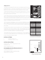
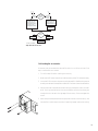
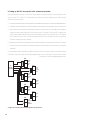
Film-Tech
The information contained in this Adobe Acrobat pdf
file is provided at your own risk and good judgment.
These manuals are designed to facilitate the
exchange of information related to cinema
projection and film handling, with no warranties nor
obligations from the authors, for qualified field
service engineers.
If you are not a qualified technician, please make no
adjuatments to anything you may read about in these
Adobe manual downloads
www.film-tech.com
Cinema Accessories
for DCA Series amplifiers
OFF
ON
USER MANUAL
1
2
3
4
PU
SH
5
6
7
8
9
10
▼
XC-3
Two-way crossover with delay
▼
LF-3
Low-frequency filter with delay
▼
SF-3
Subwoofer filter
*TD-000079-00*
TD-000079-00
Rev. A
1
© Copyright 1998 QSC Audio Products, Inc. All rights reserved.
“QSC” and the QSC logo are registered trademarks, and “DCA” and “DataPort” are trademarks, of QSC Audio
Products, Inc.
2
CINEMA ACCESSORIES FOR DCA AMPLIFIERS
I. Introduction
This manual covers setup and operation of cinema crossover accessories for QSC DCA Digital Cinema Amplifiers. These
accessories comprise three models: the XC-3 crossover, the LF-3 low frequency filter, and the SF-3 subwoofer filter.
Together with DCA amplifiers, they allow you to assemble any type of cinema sound system, mono or multi-channel.
Each accessory mounts directly to the back of the amplifier, from which
Ch. 1
LF
full-range audio
audio plein registre
Vollbereichaudio
audio de gama llena
XC-3
HF
2-way crossover
it also draws its power. It has its own input and, if necessary, output
DCA amplifier
Ch. 2
the amp through its DataPort.
Using the XC-3 in a simple two-way system. In many speaker systems, a
passive mid/high combination will handle the higher frequencies, creating essentially a three-way system.
XC-3
HF
2-way crossover
Frequency and delay parameters are user adjustable by inserting
selected 8-pin SIP resistor networks (included with each unit) into
sockets on the underside of the accessory. A DIP switch permits
Ch. 1
MF
full-range audio
audio plein registre
Vollbereichaudio
audio de gama llena
connectors. A male HD-15 connector conveys the audio signals into
DCA amplifier
selection of functions such as delay and high-frequency boost.
Ch. 2
II. Description of Functions
L
XC-3
Ch. 1
LF
LF-3
low-frequency filter
LF
band fed to channel 1 of the amplifier and the high frequencies
DCA amplifier
to channel 2. An all-pass filter on the low frequency band delays
Ch. 2
the audio signal, permitting time alignment of a cone driver
R
full-range audio
audio plein registre
Vollbereichaudio
audio de gama llena
This accessory is a two-way crossover, with the low frequency
with a high-frequency horn. A selectable high-frequency boost
circuit provides several increments of compensation for screen
loss or constant-directivity horn equalization. A HF trim control
Ch. 1
MF
XC-3
HF
2-way crossover
provides 0 to 20 dB of attenuation for matching levels
DCA amplifier
between frequency bands.
Ch. 2
Using the XC-3 and LF-3 in a stereo three-way system
The XC-3 can be used by itself with one amplifier for a 2-way
system (shown top left), or with the LF-3 and an additional
amplifier for 3-way systems, as shown at left. The XC-3 has
a pass-through output in parallel with the input for distributing
the audio signal to the LF-3. The filter circuitry uses a 4th-
Ch. 1
SF-3
order Linkwitz-Riley alignment with 24 dB/octave slopes.
DCA amplifier
subwoofer filter
Ch. 2
LF-3
Used in a system with the XC-3, the LF-3 performs the lowfrequency crossover functions in a 3-way system as shown at
left. Unlike the XC-3, though, it is a device with two discrete
Using the SF-3 with a discrete subwoofer channel
channels; one LF-3 with an amplifier will support two other
amplifiers with two XC-3 accessories, as shown. The 4th-order
Linkwitz-Riley low-pass filters have 24 dB/octave slopes.
3
Each channel also has an all-pass filter providing delay for time alignment. Frequency and delay parameters
for both channels are set individually, although in all but a few applications they would be set the same.
Each channel also has a trim control providing 0 to 20 dB of attenuation to facilitate matching levels
among the various frequency bands.
SF-3
This subwoofer filter accessory has two summed inputs and a bandpass filter that defines the frequency
range of the subwoofer program. The frequencies of the 2nd-order high-pass and 4th-order Linkwitz-Riley
low-pass filters are both user-defined. The high-pass filter also has a switchable low-frequency boost
feature: switched on, it provides a 6 dB bump at the selected high-pass frequency, useful for extending
the low-end response of some speaker systems; off, the response is a flat Butterworth curve that is
3 dB down at the selected frequency. The output is parallel, feeding the same signal into both channels
of the amplifier. The SF-3 has no delay function. A level trim control provides 0 to 20 dB of attenuation.
The SF-3 can be used to derive subwoofer-range program from full-range audio, or it can be used with
a discrete subwoofer channel in cinema sound systems.
III. Configuring the accessories
Configure each accessory before you mount it to the amplifier. If an accessory is already mounted to an amplifier,
always turn the amp off before changing switch settings or input or output connections, or detaching the accessory.
Use the tables on the following pages to determine the correct resistance for the desired frequency and delay
settings. Use the diagram at the top of the opposite page to identify the values of the resistor networks. A
+10 dB
flowchart for each model will assist you in setting the various parameters,
+5 dB
fHP
fXO
+2.5 dB
2-way
and the chassis label on each accessory also details the correct DIP switch
+7.5 dB
settings. An appendix in the back of this manual lists manufacturer-
XC-3
3-way
recommended crossover frequency and delay settings for various popular
cinema speaker systems.
LF delay
The purpose of the delay functions in the XC-3 and LF-3 is to correct for time
misalignments between different types of speaker driver in the overlap region
between adjacent frequency bands. These time misalignments occur when
fXO
the acoustical source points of the drivers for the adjacent frequency bands are
physically at different distances from the listener(s). A delay compensation
LF-3
of 1 millisecond represents approximately 1.13 ft (13.5 in), or 34.4 cm.
NOTE: Even if you don’t use a particular filter or delay feature on
an accessory, put an unused SIP resistor network of any value
into its socket to ensure circuit stability when it is powered up.
The SIP resistor networks have no polarity and therefore do not need to be
Delay
LF boost
fHP
fLP
inserted in a certain direction. Make sure all eight pins are inserted properly
Low pass filter off
into the sockets holes, and then gently but firmly press the network into the
socket until it is fully seated. If a SIP resistor network is difficult to remove
SF-3
LF flat
Low pass filter on
with your fingers, use a small screwdriver, prying gently first at one end of
the SIP and then the other, until it is loose.
4
Configurable functions of the three accessory models
Crossover freq. (fXO)
SIP resistor value
Delay (ms)
SIP resistor value
80 Hz
68K
1.8
27K
150 Hz
39K
1.4
22K
200 Hz
27K
1.3
20K
250 Hz
22K
1.2
18K
300 Hz
20K
1
15K
350 Hz
18K
0.8
12K
400 Hz
15K
0.7
10K
500 Hz
12K
0.6
8.2K
600 Hz
10K
0.5
6.8K
650 Hz
8.2K
0.4
5.6K
800 Hz
6.8K
0.3
4.7K
1 kHz
5.6K
1.2 kHz
4.7K
1.5 kHz
3.9K
RESISTANCE
2.7K
3.9K
4.7K
5.6K
6.8K
8.2K
10K
12K
15K
18K
20K
22K
27K
33K
39K
47K
56K
68K
Use only these three digits to
determine resistance code.
Disregard the other
numerals and letters.
Use these tables with the XC-3 and LF3 to determine the correct resistor
values for the crossover frequencies
and delays you need. The shaded
values are for the LF-3 and the highpass frequency (fHP) of the XC-3).
CODE
272
392
472
562
682
822
103
123
153
183
203
223
273
333
393
473
563
683
Identifying SIP resistor networks
Setting up the XC-3
This procedure involves setting the DIP switches, as well as selecting
1
and inserting SIP resistors into the appropriate sockets. Set switches
2, 9, and 10 to ON. The flowchart on the next page takes you through
OFF
ON
1 2 3 4 5 6 7 8 9 10
all the steps necessary before mounting the accessory to the amp.
1
The illustration on the next page shows the locations of the sockets for
the SIP resistor networks. The resistor networks have no polarity or
directionality and therefore do not need to be inserted in any particular
way, as long as each network pin goes into its own hole in the socket.
XC-3 controls and switches
Use the tables at the top of this
10
page to select the correct resistor
9
networks for the settings you need.
7
The SIPs supplied with the XC-3
provide a selectable frequency
range for fXO of 80 Hz to 1.5 kHz, and
delay settings from 0.3 to 1.8 milliseconds, plus bypass (no delay);
HF boost = 10 dB
8
HF boost = 7.5 dB
6
5
HF boost = 5 dB
4
3
2
HF boost = 2.5 dB
1
0
HF boost = OFF
-1
-2
-3
-4
-5
contact QSC’s Technical Services
department if your application requires different settings.
-6
500
700
1k
2k
3k
4k
5k 6k 7k 8k 9k10k
15k
20k
30k
40k 50k
Effects of high frequency boost on frequency response (crossover frequency
= 500 Hz). A boost of +10 dB is most common for compensating for screen loss
(attenuation of high frequencies as sound passes through screen perforations)
and for constant-directivity horns.
5
J1 (fXO)
3-way
2- or 3-way?
2-way
Switches 7 & 8 =
OFF
Switches 7 & 8 =
ON
Select fXO ; install
appropriate SIP in J1
Select fXO and fHP ;
install appropriate
SIPs in J1 (f XO ) and
J7 (fHP )
Install SIP (any
value) in J7*
Need LF
delay?
No
Yes
Switch 1 = OFF
Switch 1 = ON
J2 (LF delay)
Install SIP (any
value) in J2*
J7 (fHP)
Select delay; install
appropriate SIP in J2
Locations of SIP sockets on the XC-3
Need HF
boost?
When using the XC-3 in a three-way system in conjunction with the LF-3,
the lower frequency (fHP) should match the crossover frequency of the
LF-3 (fXO). The SIPs supplied with the XC-3 allow a selectable frequency
range for fHP of 80 to 500 Hz.
FACTORY SIP SETTINGS
fXO
500 Hz (12K SIP resistor in J1)
LF delay
1.8 ms (27K SIP resistor in J2)
f HP
80 Hz (68K SIP resistor in J7)
FACTORY SWITCH SETTINGS
Bi-amp mode (switches 7 & 8 = ON)
LF delay active (switch 1 = ON)
HF boost defeated (switches 3 through 6 = OFF)
Switches 2, 9, & 10 = ON
RECOMMENDED AMPLIFIER SETTINGS WITH THE XC-3
Clip limiters ON, both channels
Stereo mode
High-pass filter ON, both channels
High-pass frequency 30 or 50 Hz, both channels
6
10 dB (CD horn)
Yes
No
7.5 dB
Switches 3–6 =
OFF
2.5 dB
Switch 3 = ON;
Switches 4–6 =
OFF
Switch 6 = ON;
Switches 3–5 =
OFF
5 dB
Switch 4 = ON;
Switches 3,5, 6
= OFF
Switch 5 = ON;
Switches 3,4, 6
= OFF
*To ensure circuit stability
Attach to amplifier
Setup flowchart for the XC-3
Setting up the LF-3
J8 (Ch. 1 fXO)
J1 (Ch. 1 delay)
This procedure involves setting the DIP switches, as well as selecting and inserting SIP resistors into
the appropriate sockets. Set switches 2 and 4 through 9 to OFF, and switch 3 to ON. The flowchart
below takes you through all the steps necessary before mounting the accessory to the amp.
The LF-3 is typically used in a system in conjunction with
the XC-3 crossover. For example, a stereo three-way
system will require three DCA amplifiers, two XC-3
cinema crossover accessories, and one LF-3 lowtypical input signal is full-range audio taken from the male
ON
1 2 3 4 5 6 7 8 9 10
OFF
frequency cinema accessory, as shown on page 2. The
J6 (Ch. 2 fXO)
XLR connector labeled “OUTPUT (TO LF-3)” on the XC-3.
The illustration to the left shows the locations of the
sockets for the SIP resistor networks. The resistor net-
J2 (Ch. 2 delay)
works have no polarity or directionality and therefore do
Locations of SIP sockets on the LF-3
not need to be inserted in any particular way, as long as
LF-3 controls and switches
each network pin goes into its own hole in the socket.
Select fXO for Ch.1 and Ch. 2;
install appropriate SIPs
in J8 (Ch. 1) and J6 (Ch. 2)
Use the tables at the top of page 5 to select the correct resistor networks for the crossover
frequency (fXO) and delay settings you need. The SIPs supplied with the LF-3 provide a range
of frequency selections from 80 Hz to 500 Hz, and delay settings from 0.3 to 1.8
No
Need LF
delay?
milliseconds plus bypass (no delay); contact QSC’s Technical Services department if
Yes
Channel 1: Switch 10 = ON
Channel 2: Switch 1 = ON
Switches 1 & 10 = OFF
Install SIPs (any
value) in J1 and J2*
Select delay for Ch.1 and Ch. 2;
install appropriate SIPs
in J1 (Ch. 1) and J2 (Ch. 2)
Attach to amplifier
your application requires different settings.
When using the LF-3 in a three-way system in conjunction with the XC-3, the crossover
frequency of the LF-3 (fXO) should match the lower high-pass frequency (fHP) of the XC-3.
In most circumstances, the LF-3 would be used with an amplifier in stereo mode. But
if two amp channels are needed for one low frequency signal, you can use the Channel 1 input
*To ensure circuit stability
Setup flowchart for the LF-3
of the LF-3 and parallel the inputs of the amplifier (using the amp’s DIP switches).
FACTORY SIP SETTINGS
fXO
350 Hz, both channels (18K SIP resistor in J6 & J8)
Delay
1.4 ms, both channels (22K SIP resistor in J1 & J2)
FACTORY SWITCH SETTINGS
Delay active, both channels (switches 1 & 10 = ON)
Switches 2 and 4 through 9 = OFF; switch 3 = ON
RECOMMENDED AMPLIFIER SETTINGS WITH THE LF-3
Clip limiters ON (both channels)
Stereo mode; parallel mode in applications requiring dual LF amp channels with one source
High-pass filter ON (both channels)
High-pass frequency 30 or 50 Hz, depending on speaker (both channels)
7
Setting up the SF-3
This procedure involves setting the DIP switches, as well as selecting and inserting SIP resistors into
the appropriate sockets. First, set switches 1 through 6 and 10 to OFF. The flowchart on the opposite
page takes you through all the steps necessary before mounting the accessory to the amp.
OFF
ON
1 2 3 4 5 6 7 8 9 10
The bottom right illustration details the locations of the two SIP sockets used on the SF-3. The resistor
networks have no polarity and therefore do not need to be inserted in any particular way, as long as
each pin goes into its own hole in the socket.
The mono subwoofer program can be derived from summing and filtering stereo or mono full-range
audio, or it can come from a discrete mono subwoofer channel, such as in a 5.1, 6.1, or 7.1 cinema
surround system. If the subwoofer program is to be derived, use the SF-3’s low-pass filter to set the
SF-3 controls and switches
high end of the subwoofer passband. If the subwoofer program source is a discrete channel, as in most cinema
systems, we recommend that you bypass the low-pass filter.
The SF-3’s two inputs are summed together, so you can use one or both, depending on your system
Low-pass freq. (fLP)
SIP resistor value
needs. The outputs to the two amplifier channels are monaural and in parallel, unlike the XC-3 and
80 Hz
68K
LF-3. Thus, SF-3 is the only DCA accessory that can be used with the amplifier in bridged mono mode,
150 Hz
39K
when necessary.
250 Hz
22K
Use the table at right to select the correct resistor networks for the SF-3’s filter frequency settings.
High-pass freq. (fHP)
SIP resistor value
An identification chart for SIP resistor networks is on page 5. The SIPs supplied with the LF-3 provide
20 Hz
47K
a selection of three low-pass frequencies: 80, 150, and 250 Hz; and six high-pass frequencies from
25 Hz
33K
20 to 50 Hz. Use the speaker manufacturer’s recommended filter settings.
30 Hz
27K
35 Hz
20K
40 Hz
15K
50 Hz
10K
The low-frequency boost switch selects the Q of the high-pass filter: 0.707 for flat (Butterworth),
or 2 for “boost,” which adds a 6 dB peak at the filter’s selected frequency. Some speakers require
this boost to extend the low-frequency response.
FACTORY SIP SETTINGS
f HP
30 Hz (27K SIP resistor in J2)
f LP
250 Hz (22K SIP resistor in J1 & J2)
Use this table to determine the correct
resistor values for the SF-1 filter frequencies.
FACTORY SWITCH SETTINGS
Low-pass filter OFF—”cinema” setting (switches 7 & 8 = ON)
LF flat (switch 9 = OFF)
Switches 1 through 6 and 10 = OFF
J6 (fLP)
RECOMMENDED AMPLIFIER SETTINGS WITH THE SF-3
Clip limiters ON (both channels)
Stereo or bridged mono mode, as the application dictates
High-pass filter OFF (both channels)
J2 (fHP)
Locations of SIP sockets on the SF-3
8
high- lowpass pass
Derived
by filter
highpass
Is subwoofer
program derived or
discrete?
Turn low-pass filter on
Switches 7 & 8 = OFF
Turn low-pass filter off
Switches 7 & 8 = ON
Select high-pass freq. (fHP);
install appropriate SIP in J2.
Select low-pass freq. (fL P);
install appropriate SIP in J6.
Select high-pass freq. (fHP);
install appropriate SIP in J2.
No
From discrete
subwoofer
channel
Install SIP (any
value) in J6*
Need LF
boost?
Switch 9 = OFF
Yes
Switch 9 = ON
Attach to amplifier
*To ensure circuit stability
Setup flowchart for the SF-3
IV. Mounting the accessories
An accessory may be mounted with the amplifier either in or out of the rack, even if the
amp is installed with rear rack ears.
1. Turn off the amplifier before installing the accessory.
2. Make sure the SIP resistor networks are installed properly and no SIP sockets are empty.
3. Line up the HD-15 connector on the accessory with the amplifier’s DataPort, then press the
accessory onto the back of the amplifier so that the HD-15 connector inserts into the DataPort.
4. Use the three screws supplied to secure the accessory to the amplifier chassis, as shown
at left. Two long screws go into the holes near the DataPort, while the short screw goes
through the hole in the tab on the right edge of the accessory. Do not overtighten the
screws.
5. Attach the input and output cables to the appropriate connectors on the accessory. Use
the amplifier’s normal output connectors for attaching speaker and monitor cabling.
9
V. Setting up the DCA accessories in the cinema sound system
Setting up the DCA accessories in the B chain of the cinema sound system primarily involves setting the trim
levels on the XC-3, LF-3, and SF-3. This requires the pink noise source in the cinema processor and a real-time
acoustical spectrum analyzer.
1. Set up the analyzer microphone in the center of the cinema audience seating area or in another recommended location.
2. Set the gain controls wide open for all the DCA amplifiers, and check the HF boost settings on the XC-3 accessories.
3. Apply a pink noise test signal from the cinema processor to the left channel XC-3 input. Watch the frequency
response on the analyzer and use the HF trim control on the XC-3 and the LF trim on the LF-3 to balance the
levels of their frequency bands to that of the the mid-frequency band, within specifications. If the shape of
the HF response is not correct, use a boost setting that better corrects the deficiency; turn the amplifiers
off before changing the switch settings.
4. Repeat this process for the center and right screen channels and any surround channels that are bi- or tri-amped.
5. Follow the processor instructions for setting sound pressure level outputs of all the channels, including the
subwoofer.
If you are unable to obtain a satisfactory frequency response or SPL on a channel, carefully check the wiring and
connections. Some likely causes are reversed speaker polarity on one or more drivers; loose or broken wiring or
connections; or blown or damaged speaker drivers.
DCA
2
Left
MF
Left
HF
DCA
LF-3
1
DCA
1
XC-3
L
C
5.1
Cinema R
Processor LS
RS
Sub
XC-3
1
2
Center
MF
Center
HF
2
DCA
LF-3
1
DCA
XC-3
1
2
Right
MF
Right
HF
2
SF-3
1
2
Right
LF
Spare
DCA
1
DCA
Left
LF
Center
LF
2
Sub
Sub
Left
Surround
Right
Surround
A typical 5.1 surround system with DCA amplifiers and accessories
10
APPENDIX
Crossover and delay settings for popular cinema loudspeaker systems
Consult your speaker documentation. Some data has not yet been determined. Also, the high-frequency horn
of some of the systems listed have multiple mounting positions, so the desired delay settings will depend on
the positioning chosen. Check the QSC website (http://www.qscaudio.com) for information updates.
Brand
JBL
Model
Crossover
frequency (Hz)
Delay (ms)
4675C
500
1.8
4670D
800
0.7
3678
1K
0
TS9040D-LX
500
1.8
TS550D-LX
500
1.8
TS550DMT-LX
500
1.8
TS940D
500
TS992-LX
1.2K
0
TS993-C
400
0
Variplex-B
350
LF: 1.4
Variplex
350 & 1.5K
LF: 1.4
KPT-940.L
500
1.2
KPT-904.M
800
0.3
CB2591
500
CB2592
500
CB259
500
CB152
1200
CB153
350
CB523
300
Electro-Voice
Klipsch
EAW
Martin Audio
MC 4973
300 & 1.8K
MC 4973B
300
MC 4953
300 & 1.8K
MC 4953B
300
Screen 4
650
11
© Copyright 1998 QSC Audio Products, Inc. All rights reserved.
“QSC” and the QSC logo are registered with the U.S. Patent and Trademark Office.
QSC Audio Products, Inc.,
12
1675 MacArthur Boulevard Costa Mesa, California 92626 USA
PH: (714) 754-6175 FAX: (714) 754-6174