1
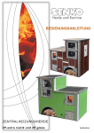
Central heating COOKERS 2P-extra rustik and 2P -glass SN-EN-04/14 Dear client, thank you for choosing a SENKO cooker ! This product was designed and manufactured to its minutest details in order to fulfill your every need for functionality and safety. This Instruction manual will teach you to operate your cooker properly, so please read the manual carefully before using the cooker. Senko management Symbols used in this INSTRUCTION MANUAL : ATTENTION SAFETY WARNING ADVICE AND RECOMMENDATIONS SENKO cookers 2P extra rustik and glass – Instruction manual 1 CONTENTS 1. GENERAL .............................................................................................4 1.1. FUEL ................................................................................................6 1.2. FEEDING ..........................................................................................6 1.3. CHIMNEY ..........................................................................................7 1.3.1. CHIMNEY CAP ...........................................................................7 1.3.2. CHIMNEY FUNCTION ..................................................................8 1.4. INSULATION ...................................................................................10 2. WARNINGS AND SAFETY .................................................................10 3. TECHNICAL FEATURES ....................................................................11 4. INSTALLATION ...................................................................................13 4.1. POSITIONING .................................................................................13 4.2. CHIMNEY PREPARATION AND CONTROL .......................................14 4.3. CONNECTING TO CHIMNEY ............................................................14 4.4. FRESH AIR VENTS ..........................................................................16 4.5. OVEN THERMOMETER....................................................................17 4.6. CENTRAL HEATING SYSTEM CONNECTION....................................17 4.6.1. COOKER THERMAL PROTECTION ..............................................19 4.6.1.1. Thermal two-way safety valve ................................................20 4.6.1.2. Thermal safety valve.............................................................21 4.6.1.3. Anti-freezing protection .........................................................22 4.6.1.4. Heat exchanger ..................................................................23 4.6.2. INSTALLATION TESTING ...........................................................24 4.6.3. RECEIVING AND MAINTAINING THE INSTALLATION .......................24 5. HANDLING THE PRODUCT ...............................................................25 5.1. DIRECTING THE FLUE GAS ............................................................25 5.2. AIR ADJUSTMENT AND REGULATION..............................................26 5.3. FIREBOX GRATE.............................................................................28 5.4. FIRING ............................................................................................29 SENKO cookers 2P extra rustik and glass – Instruction manual 2 5.4.1. PROCEDURE ...........................................................................29 5.4.2. OPTIMUM USE VALUES .............................................................29 5.4.3. ADDING FUEL ..........................................................................30 5.4.4. FEEDING IN TRANSITION PERIOD ...............................................31 5.5. OVEN DOOR ...................................................................................32 6. CLEANING ..........................................................................................33 6.1. CLEANING THE FLUE GAS CHANNEL .............................................33 7. MAINTENANCE ..................................................................................34 7.1. AUTOMATIC REGULATOR ..............................................................34 7.2. FIRING REGIME SWITCH MECHANISM............................................36 7.3. OLD COOKER DISPOSAL ................................................................36 7.4. SPARE PARTS.................................................................................36 8. MALFUNCTIONS / CAUSES / SOLUTIONS ......................................37 9. TECHNICAL SUPPORT ......................................................................39 10. TECHNICAL DATA .............................................................................40 11. TERMS OF WARRANTY ....................................................................41 WARRANTY ..............................................................................................42 INSTALLATION REPORT .........................................................................43 CE MARKING ............................................................................................44 SENKO cookers 2P extra rustik and glass – Instruction manual 3 1. GENERAL Solid fuel central heating cookers E2125 L/D C-20 2P extra rustik E2135 L/D C-30 2P extra rustik E2220 L/D C-20 2P glass E2230 L/D C-30 2P glass E2420 L/D C-20 2P glass design E2430 L/D C-30 2P glass design are models from the SENKO cookers palette which can accommodate your needs in the best possible way. Therefore, we ask you to CAREFULLY READ THESE INSTRUCTIONS, which will help you to achieve the best possible results already during the initial use. The manufacturer is not responsible for any consequences (people or animal injuries or property damages) resulting from failure to comply with this Manual. The cooker is hot during operation and the use of protective heat insulated gloves is compulsory during handling. Children and infirm individuals are not allowed to handle the cooker. The external appearance of the cooker is shown on the first page of this Manual. Cooker principal parts are made of stainless steel boiler plates and castings of quality grey cast. The cookers are produced with flue gas connection point on the left or the right side. When ordering the cooker or the spare parts, it is necessary to state its full designation, for example: cooker E2220D C-20 2P glass, which means that it is the cooker with glass coating and the flue gas connection is on the right side, if the stove is observed frontally. The cookers are manufactured and certified in accordance with the EN 12815 standard and comply with all the requirements set by this standard. SENKO cookers 2P extra rustik and glass – Instruction manual 4 These SENKO cookers are intended for cooking, baking, space heating and central heating! The cooker is packaged in a EURO pallet. During transport, the cooker must be properly fastened in order to prevent tumbling or damages. The standard delivered cooker set consists from: cooker, instruction manual, chimney terminal extension (23), firing regime adjustment – grate lifting spanner (24), cooker cleaning tool (25), CF agent for removal of soot and grease from glass surfaces (26). figure 1 25 23 26 24 CAUTION! The cooker weighs between 450 and 550 kg. Extra caution is necessary when unloading, transferring, moving and installing the cooker in order to avoid physical injury. SENKO cookers 2P extra rustik and glass – Instruction manual 5 1.1. FUEL The use of moist and low-calorie wood is not recommended. The wood moisture must be lesser than 17%. The energy content of moist wood is low, at approx. 2,3 kWh/kg and it greatly pollutes the door glass, as well as the chimney and the cooker. Use only recommended fuel : wood: common beech, common hornbeam, oak, black locust air dried for a minimum of 2 years relative humidity 15-17%, energy content at approx. 4,2 kWh/kg 1.2. wood briquettes: energy content at approx. 4,4 kWh/kg FEEDING manually when necessary we recommend the logs to be of 50 x 50 mm vertical cut, up to 2/3 of the firebox length use smaller logs for a more intensive fire, and more massive logs to maintain fire the minimum distance between the logs must be 1 cm, the same distance of 1 cm applies for the briquettes to maintain constant oven temperature, add smaller quantities of fuel occasionally approx. 0,5 kg it is necessary to use protective heat insulated gloves when adding fuel to the firebox protective heat insulated gloves must also be used when opening and closing the oven and firebox door and removing the tray from the oven and ash box SENKO cookers 2P extra rustik and glass – Instruction manual 6 1.3. CHIMNEY The cooker is connected to the chimney via 150 mm diameter sliding rosette. It is necessary to execute the connection of the rosette and the chimney tightly and impermeably. If the cooker is separated from the chimney opening (not recommended) the connection is made via standard 150 mm diameter smoke venting pipe. We also advise to equip the chimney with solid material and possible condensation products collection chamber and to install the chamber in question beneath the smoke channel inlet, in a manner which allows easy access and inspection via impermeable door. 1.3.1. CHIMNEY CAP Chimney cap must fulfill the following prerequisites: identical internal cross-section to that of the chimney, operational exit cross-section no less than the double inner cross-section of the chimney, constructed to prevent rain, snow, leaves and other foreign bodies from entering the chimney, constructed to enable expulsion of combustion products in case of wind from any direction and incline, installed to enable proper dispersion and dilution of combustion products outside the reflux zone (backflow) because the counter pressure occurs here. Therefore, it is necessary to adhere to limitations listed in figure 2, mechanical appliances for flue gases suction are not allowed. SENKO cookers 2P extra rustik and glass – Instruction manual 7 FLAT ROOF PITCHED ROOF Z=REFLUX ZONE figure 2 Roof slope 15° 30° 45° 60° Distance between the roof ridge and the chimney A, m < 1,85 > 1,85 < 1,5 > 1,5 < 1,3 > 1,3 < 1,2 > 1,2 Minimum chimney height (measured from the roof surface) Hmin, m 0,5 m above the roof ridge 1 m from the roof 0,5 m above the roof ridge 1,3 m from the roof 0,5 m above the roof ridge 2 m from the roof 0,5 m above the roof ridge 2,6 m from the roof 1.3.2. CHIMNEY FUNCTION Among all the meteorological and geographical factors that influence the chimney function (rain, fog, snow, insolation period, etc.) the wind is most certainly the crucial one. Apart from the pressure caused by the temperature difference between the flue gases and the outer chimney air, there is another type of pressure – wind dynamic pressure. SENKO cookers 2P extra rustik and glass – Instruction manual 8 Ascending wind ALWAYS has the effect of increasing the pressure, i.e., underpressure (flue draught), provided the chimney is properly installed. Descending wind ALWAYS has the effect of decreasing the draught overpressure occurs. Apart from wind direction and velocity, chimney position in relation to the house roof and surrounding area is also important (figure 3). Unfavorable position Favorable position Descending wind under 45 angle and 8 m/s overpressure of 17 Pa Horizontal wind 8 m/s underpressure of 30 Pa wind High (positive) pressure zone OVERPRESSURE figure 3 Low (negative) pressure zone UNDERPRESSURE Flue gases from the cooker The wind also influences the chimney function indirectly by creating areas of high (overpressure) and low (underpressure) pressure, both inside and outside the residential area (figure 4). Pressure that facilitates chimney function can occur in rooms directly exposed to the wind (B), but it can also adversely affect the chimney through external pressure if the chimney is situated on the side exposed to wind (A). Contrary to that, underpressure can occur in lee rooms (C), adversely affecting functions of the chimney situated on the opposite side (D) from the wind direction. SENKO cookers 2P extra rustik and glass – Instruction manual 9 Descending wind figure 4 A D wind B C A-B zones in overpressure C-D zones in underpressure 1.4. INSULATION The cooker is insulated in the boiler area towards the external surfaces with fire resistant rock wool, 20 mm thick. Other internal cooker parts are insulated with chamotte brick, 25 mm thick. Chamotte brick, 60x60 mm is used around the upper frame. 2. WARNINGS AND SAFETY When connecting the cooker to the chimney and the central heating system, adhere to national and European norms and local regulations. Prior to use, verify with the local authorized chimney-sweeper whether the cooker is properly connected to the chimney (the chimney-sweeper must complete the installation report at the end of this Manual). Special attention must be paid that there is enough air for combustion being supplied to the room cooker is installed in. Prior to commencing the firing procedure, the cooker MUST be connected to waterworks and central heating installation. The procedure may only be executed by an authorized expert who completes the installation report at the end of this Manual. SENKO cookers 2P extra rustik and glass – Instruction manual 10 3. TECHNICAL FEATURES SENKO cookers 2P extra rustik and glass are intended for cooking, baking, sanitary water heating and household heating. They are constructed on the model of old brick kitchen cookers which had large ovens. They are made of stainless steel boiler plates and castings of quality grey casts. The boiler is made of 5 mm thick boiler plate. The cooking plate (1) is made of 8 mm thick fireproof plate. Cooker interior is lined with chamotte and chamotte plates. Exterior plates can consist of ceramic tiles or tempered glass in different colours. The ash box (14) is on the frontal side, at the bottom, above it is the secondary air regulator (11) (behind the protective cover) and the firebox (8). Connections for the central heating system are on the rear side of the cooker. Cooker firebox (8) can function as both summer and winter firebox, depending on the position of the firebox lower grate. figure 5 SUMMER FIREBOX cooking, baking and sanitary water heating WINTER FIREBOX cooking, baking, sanitary water heating and radiators heating The following figures display the schematics of the cooker and their accompanying parts. SENKO cookers 2P extra rustik and glass – Instruction manual 11 SCHEMATIC DISPLAY FOR 2P COOKER RIGHT COOKER 2P - rear end view LEFT COOKER 2P - rear end view figure 6 THE KEY : 1. 2. 3. 4. 5. 6. 7. 8. 9. 10. 11. 12. Cooking plate Frame Cooker base Cooker housing Lower door Top plate Boiler with base Firebox door Oven with door Cleaning hatch lid Secondary air regulator Primary air automatic regulator 14. Ash box 15. Fuel box 16. 17. 18. 19. Chimney connection point Flue gas deflector R1’’ cold water connection point R1/2’’ inlet water connection point of the boiler thermal protection 20. R3/4’’ two-way safety valve connection point of the boiler thermal protection (see page 20), i.e. boiler thermal protection safety valve probe (see pgs. 21, 22 and 23) 21. R1/2’’ outlet water connection point of the boiler thermal protection 22. R1’’ warm water connection point SENKO cookers 2P extra rustik and glass – Instruction manual 23. Chimney connection point extension 24. Firing regime adjustment spanner 25. Cooker cleaning tool 26. CF agent for removal of soot and grease from glass surfaces 27. Door hinge bolt 28. Firebox door glass 29. Oven door glass 30. Primary air inlet hatch 31. Oven door hinge 32. Oven thermometer 12 4. INSTALLATION Once you have removed packaging from the cooker, it is necessary to make a detailed inspection in order to determine any potential damages that might have occurred during transport. Nay detected damages must instantly be reported to the manufacturer. In places of any connection points on the cooker (water, thermal protection, chimney, air inlet), inspection hatches must be installed for system maintenance and servicing purposes. 4.1. POSITIONING A spirit level must be used to place the cooker in a horizontal position with no incline. It is necessary to ensure the minimum distance of the cooker from any flammable objects; such as wood, chipboard, cork and similar. If the materials are easily combustible such as PVC, polyurethane and similar, the necessary safety distances need to be doubled. The minimum distance from any flammable surfaces above and in front of the cooker is 800 mm, and 200 mm in all other directions. When mounting the cooker on the floor made from easily combustible material (wooden floors), the cooker must be mounted on an insulating non-combustible surface, 60 mm thick. The surface must cover the layout area of 800 mm in front of the cooker and 400 mm in all other directions. It is explicitly RECOMMENDED by the manufacturer to place the cooker as close as possible to the chimney hole, i.e. next to the chimney hole itself in order to avoid using an additional smoke uptake pipe. If the additional smoke uptake pipe is not used, maximum efficiency of the cooker, i.e. fuel is additionally assured ! SENKO cookers 2P extra rustik and glass – Instruction manual 13 4.2. CHIMNEY PREPARATION AND CONTROL Prior to cooker mounting, it is necessary to check the chimney – the diameter, height, possible clogging or damages. The chimney must be certified by an authorized local chimney-sweeper. The effective chimney height must be at least 5 meters from the point of flue gases outlet (figure 7b). Flue draught must be within parameters: for C-20 2P 12 ± 2 Pa, for C-30 2P 15 ± 2 Pa. The chimney must be at least 0,5 meters above the roof ridge. The minimum distance between the two connections on the same chimney must be 60 cm (figure 7d). Chimney diameter is chosen according to information provided by the chimney manufacturer – e.g., for flue draught of 15 Pa, the diameter is usually 160 mm. The chimney must be smooth on the inside, well insulated and well fastened. All cleaning hatches must be well fastened. All gaskets must be regularly inspected and replaced when necessary. 4.3. CONNECTING TO CHIMNEY When connecting the cooker to the chimney it is necessary to adhere to local, national and European regulations (norms) – DIN 4705. It is necessary to ensure that the connection between the cooker and the chimney is executed tightly and impermeably. Smoke outlet pipe must have a suitable incline in cases where the cooker is removed from the chimney opening. Smoke outlet pipe must not penetrate into the chimney clear opening (figure 7c). Differences between the proper and improper connection of the cooker to the chimney are displayed in the following figure. SENKO cookers 2P extra rustik and glass – Instruction manual 14 PROPER IMPROPER figure 7 Differences between the proper and improper connection of the cooker to the chimney SENKO cookers 2P extra rustik and glass – Instruction manual 15 Connect the cooker to the chimney using a sliding rosette, 150 mm in diameter. Specially designed sliding rosette enables the adjustment of the chimney opening in tolerance of 1,5 cm upwards, i.e. downwards. In case it is necessary to keep the cooker removed from the chimney opening, use the standard smoke outlet pipe, 150 mm in diameter. It is not allowed to reduce the prescribed pipe diameters ! If the cooker is further removed from the chimney opening, it is connected via extension tube and an elbow. The extension smoke inlet pipe must have an appropriate incline and must not exceed 125 cm in length. The connection of the chimney and the smoke inlet pipe must be completely fastened ! figure 8 Remove the external protective lid with a screwdriver Remove the sheet beneath the lid by pressing onto the weakest juncture Mount the protective lid onto the remaining chimney opening! Remove the internal protective lid with a screwdriver Install the sliding rosette by using bolts previously used to attach the inner protective lid Install the external protective sheet by using bolts previously used to attach the external protective lid 4.4. FRESH AIR VENTS The room where the cooker is installed must be provided with sufficient air inflow to ensure combustion. The area must be regularly ventilated. SENKO cookers 2P extra rustik and glass – Instruction manual 16 The fresh air vent must be situated near the room floor and allow the inflow of fresh air into the room. The minimum dimension of the vent must be 6 cm per kW of nominal power (e.g. for 30 kW 180 cm 2 2 10 x 18 cm vent). A pipe can also be installed on the existing opening 150 x 80 mm (30) on the rear side of the cooker for the purpose of entering fresh outside air. 4.5. OVEN THERMOMETER Thermometer (32) indicates the oven temperature; this value is informative. If the oven temperature exceed 300 C, the oven must be partly opened to prevent damage to the thermometer, oven door hinge and oven door. The warranty will be void in case the damage to the parts listed before occurred from excessive oven temperature. 4.6. CENTRAL HEATING SYSTEM CONNECTION Prior to commencing the firing procedure, the cooker must be connected to waterworks and central heating system and the boiler must be filled with water. Continuous circulation of water through the boiler must be ensured. The boiler must be well deaerated prior to operations commencement. The pipe installation must be executed in accordance with valid technical regulations and DIN 4751 norm – part 1 for open systems and DIN 4751 – part 2 for closed systems, following professional standards, and only by an authorized expert. It is not allowed to reduce the diameter of the pipe connecting the boiler to the heating installation connection point. Otherwise, the warranty will be void. SENKO cookers 2P extra rustik and glass – Instruction manual 17 Prior to connecting the boiler to the heating installation, the pipelines are to be thoroughly cleansed from potential filth sediments. This prevents boiler overheating, system noise, pump malfunctions and mixing valve malfunctions. The connection to the heating system is executed via union flat joint, with or without the mixing valve onto an open or closed system. Open central heating system figure 9 Closed central heating system SENKO cookers 2P extra rustik and glass – Instruction manual 18 Installation of an approved safety valve with opening overpressure set to 2,5 bar is mandatory in closed systems. Safety and expansion conduits must not have any kind of block elements. It is necessary to install the deaerating valve. When filling the boiler and the radiator system it is necessary to open the mixing valve, if one had been installed; adequately deaerate the boiler and the heating system. The mixing valve (7 – figure 9) maintains the boiler temperature at minimum the 60C, thus preventing the boiler from condensation. If one had not been installed, it is necessary to ensure firing conditions that will prevent boiler condensation. Condensation may appear at the beginning of the firing process or due to insufficient feeding. Pipeline thermostat which activates the circulation pump must not be adjusted to values lower than 60C ! 4.6.1. COOKER THERMAL PROTECTION When connecting the cooker to the central heating system it is necessary to install the safety thermal valve. It shall be installed on the cooker rear side to R3/4’’ connection point – inner threadfigures10-13. Water outlet into the sewer (or SW tank – sanitary water) is connected to connection point: R3/4'' (7) - figure 10, OR R1/2'' (7) - figure 11, OR R3/4'' (8) - figure 12. The sensor (probe) of the safety thermal valve is connected to the connection point (5) broken line in figures 10-13. The central heating system must have its own separate thermomanometer! THE BOILER MUST NOT BE USED WHEN EMPTY OF WATER ! SENKO cookers 2P extra rustik and glass – Instruction manual 19 SENKO cookers 2P extra rustik and glass – Instruction manual figure 10 Orientational schematic for cooker connecting to a central heating system with a thermal two-way safety valve 4.6.1.1. THERMAL TWO-WAY SAFETY VALVE 20 THERMAL SAFETY VALVE 4.6.1.2. Orientational schematic for connecting the cooker to the central heating system with CALEFFI 544400 thermal safety valve figure 11 21 SENKO cookers 2P extra rustik and glass – Instruction manual SENKO cookers 2P extra rustik and glass – Instruction manual figure 12 Orientational schematic for connecting the cooker to the central heating system with anti-freezing protection (antifreeze) 4.6.1.3. ANTI-FREEZING PROTECTION 22 HEAT EXCHANGER 4.6.1.4. Orientational schematic for connecting the cooker to the central heating system with a heat exchanger (buffer) figure 13 23 SENKO cookers 2P extra rustik and glass – Instruction manual 4.6.2. INSTALLATION TESTING Prior to initial firing it is necessary to check if the boiler and the entire heating system are filled with water and well deaerated. Also check if the smoke uptake pipe is properly fastened. After initiation make sure: there is no leakage of any kind, that the entire installation is deaerated, that the water temperature in the boiler is increasing, that boiler operations do not result in condensation (“sweating”) in the chimney. Repeat the entire inspection after several days of constant feeding ! Also, PRIOR TO INSTALLATION activate the safety valve and check its proper functionality. 4.6.3. RECEIVING AND MAINTAINING THE INSTALLATION When receiving the installation, inspect the installation in its entirety with the contractor. The contractor is obligated to provide basic information about the installation operations and indicate the position and function of the installation key components. Also, the contractor is obligated to complete the installation report which can be found at the end of this Manual ! Deaerate the entire heating system after several days and refill it with water if necessary. Inspection of installation working performance is to be executed at least once a year by an authorized maintenance technician. This will ensure safe working performance of the boiler, as well as economic and immaculate heating. In case of installation faulty operation, contact your central heating installation contractor exclusively ! SENKO cookers 2P extra rustik and glass – Instruction manual 24 5. HANDLING THE PRODUCT holding the cooker frame is not allowed while handling the appliance ! 5.1. DIRECTING THE FLUE GAS Flue gas deflector (17) accelerates the expulsion of flue gas from the cooker when this is necessary. It is primarily used during initial stages of extra rustik cooker firing or when larger quantities of fuel are added into the firebox. AWAY FROM OVEN TOWARDS OVEN figure 14 OR closed flue gas deflector (17) flue gases orbiting the upper and lower oven glass cooker opened flue gas deflector (17) flue gases coming out directly into the cimney Using the flue gas deflector (17) can be regulated also an oven temperature (9) if the flue gas deflector is open, the oven cools. SENKO cookers 2P extra rustik and glass – Instruction manual 25 5.2. AIR ADJUSTMENT AND REGULATION CHIMNEY If the chimney is equipped with a vent damper, it must be adjusted to keep the chimney flue draught within the limitations: for C-20 2P 12 ± 2 Pa, for C-30 2P 15 ± 2 Pa. PRIMARY AIR Primary air is the air that flows directly through the firebox grate. There is an automatic max primary air regulator (12) between the fuel box (15) and ash box (14). Its probe, which measures min the temperature of the water in the boiler, is placed on the boiler frontal side under the lid, between figure 15 upper and lower door. Turning the PVC wheel of the automatic regulator regulates primary air flow. Regulator is set in accordance with the desired boiler water temperature. The division ranges from min (thin end of the semicircle) to max (wide end of the semicircle) : min automatic regulator is closed and there is no primary air flow, max primary air opening is completely open and the flow is at its maximum. SENKO cookers 2P extra rustik and glass – Instruction manual 26 There is a rectangular connection point for the intake of external primary air on the cooker rear side, onto which a rectangular pipe (30), dimensions 150 x 80 mm, can be connected. If necessary, the rectangular cross-section may be reduced and turned into a round opening (minimum diameter 100 mm). The connecting pipe or the reduction must be made out of non-flammable material (in accordance with DIN 4102-B1). figure 16 primary air connection point (30) on the cooker rear end SECONDARY AIR Secondary air is the air that flows into the firebox to facilitate maximum combustion, reducing harmful substances to ashes and discharging flue gas with low capacity for pollution into the chimney. Secondary air regulator (11) is placed on the cooker front side under the lid, between upper and lower door. The regulator is factory set for wood and wood briquettes as fuel. If you use some other fuel (e.g. coal), the regulator must be adjusted manually. SENKO cookers 2P extra rustik and glass – Instruction manual 27 5.3. FIREBOX GRATE Cooker firing regimes differ during summer and winter (winter and summer regime) – figure 5. The regimes are determined by the position of the lower firebox grate. In C-30 2P cooker : summer regime – the grate is used in the upper firebox position, winter regime – the grate is manually placed into the lower firebox position. In C-20 2P cooker the grate is positioned via special mechanism : summer regime – the grate is elevated as necessary, winter regime – the grate is lowered. Grate adjusting mechanism is placed in the lower door opening (5). Firing regime adjustment spanner (24) is used to elevate the grate. Once the grate has been placed in the desired position, the spanner must be removed from the mechanism; otherwise the lower door (5) cannot be closed. figure 17 firing regime adjusting mechanism in C-20 2P cooker with regime adjustment spanner (24) wide grate openings must be positioned facing upwards at all times to allow the ashes to fall down! grate lifting and lowering is executed ONLY when the cooker is cold ! SENKO cookers 2P extra rustik and glass – Instruction manual 28 5.4. FIRING 5.4.1. PROCEDURE Prior to every firing, follow the following procedure : if the chimney is equipped with a vent damper, open it completely, open the flue gas deflector (17) and set the automatic primary air regulator (12) to maximum, open the firebox door (8) (maximum door opening angle is 90), put the kindle wood into the firebox and ignite it, close the firebox door (8), monitor flame progression through the firebox door, once the fire is in full flame, add wooden logs as necessary, close the flue gas deflector (17), regulate the fire intensity by regulating the volume of primary air via automatic regulator (12), primary air MUST NEVER be supplied in any other manner when the automatic regulator (12) is used ! WARNING! Never use flammable liquids, such as petrol and similar to ignite the fire and always keep these and similar liquids away from your cooker. 5.4.2. OPTIMUM USE VALUES Primary air volume and chimney flue draught must be adjusted to levels that prevent boiler water temperature from exceeding 85C. Maximum quantity of fuel that can be accommodated in the firebox: 6 kg for C-20 2P cooker, 8 kg for C-30 2P cooker. SENKO cookers 2P extra rustik and glass – Instruction manual 29 Adding fuel in regular intervals, in quantities of 2 to 4 kg, is recommended. When using the oven for baking, it is recommended (to maintain constant temperature in the oven) to add 0,5 kg of fuel in regular intervals. It is also recommended to rotate the tray from 180 halfway through the baking process to ensure uniform baking ! Cooker optimum values may be achieved only if the cooker nominal power was chosen in accordance with the rules of profession and object energetic efficiency. 5.4.3. ADDING FUEL Apart from use of appropriate fuel and satisfactory chimney flue draught, the manner in which the cooker is fuelled also influences the glass cleanness. We recommend only one layer in each fuel refill and, if possible, the use of logs of length up to 2/3 of the firebox length. There should be a minimum distance of 1-2 cm between the logs. figure 18 Briquettes should be used in amount that only covers the firebox surface, also with a minimum distance of 1-2 cm between them. SENKO cookers 2P extra rustik and glass – Instruction manual 30 WARNING! New fuel quantities should be added only on top of embers, i.e., not on the flames, but only on top of embers (approx. 1 cm thick). Primary air automatic regulator (12) must be completely closed at least ten seconds before opening the firebox door (8) to prevent the breach of flue gases into the residential area. The door must be opened slowly. After adding the fuel, close the door slowly. Open the primary air automatic regulator (12) to decrease the time of fuel combustion. Once the fuel starts burning, adjust the primary air automatic regulator (12) to a desired position in accordance with chapter 5.2. Flue gas deflector (17) MUST BE opened before opening the door ! 5.4.4. FEEDING IN TRANSITION PERIOD During the transition period, i.e. when outdoor temperatures are higher, sudden increase in outdoor temperature can cause chimney malfunction (decreased chimney flue draught) resulting with not all flue gases being expelled into the atmosphere. It is therefore recommended to use less fuel and smaller logs during the transition period in order to achieve a more lively flame, as well as to adjust the primary air volume in order to improve the expulsion of flue gases from the chimney. SENKO cookers 2P extra rustik and glass – Instruction manual 31 5.5. OVEN DOOR Oven door are removed as shown in the following figure : figure 19 open the oven door all the way move the safety all the way back on the left and right oven hinges close the door halfway ensuring that the safeties lean against the door slits lift the ajar door upwards for approx. 2 mm and lightly pull them towards yourself, inclining the door toward the cooker simultaneously pull the door from the cooker hinge bearing Reverse the procedure to mount the door back ! WARNING! Always make sure that the hinge safeties properly fit in their bearings prior and after the removal of door! Otherwise they might suddenly pop out during door removal or mounting, i.e. the hinge might suddenly close due to strong springs, which might cause injuries ! SENKO cookers 2P extra rustik and glass – Instruction manual 32 6. CLEANING The cooker and the chimney must be regularly cleaned (at least once a month). The ash box (14) and the box area must be cleaned on daily basis. Ash disposal is to be executed in environmentally acceptable manner and in accordance with safety procedures. The glass (28) on the upper firebox door (8) should be cleaned as necessary using the soot and grease cleaning agent (26). The agent is delivered with the cooker ! The oven (9) should be cleaned after every instance of use. 6.1. CLEANING THE FLUE GAS CHANNEL While cleaning the top side of the cooker (figure 20), it is necessary to remove the top plate (6) and cleaning hatch lids (10) which are located at the bottom of each oven, and thoroughly clean the soot from the boiler, around the ovens and flue gas deflector, including the chimney outlet opening (16). figure 20 Cooker cleaning is to be performed only when the cooker is inactive and when it is cold ! SENKO cookers 2P extra rustik and glass – Instruction manual 33 7. MAINTENANCE Following years of use, the chamotte insulation (consumable material) suffers damage that must be repaired with chamotte putty or refractory concrete. After several first hours of feeding, smear the fireproof paint on the upper plate with a cloth imbued with edible oil. Stainless material on the cookers is susceptible to slight colour change due to high temperatures. Stainless materials are to be maintained exclusively with stainless material maintenance agents in accordance with the manufacturer’s instructions. Handle securing bolt on upper and lower doors and firebox door protective bolt to be tightened if necessary. 7.1. AUTOMATIC REGULATOR When replacing the automatic regulator, adhere to the following procedure: remove the automatic regulator PVC wheel (12) by pulling it towards yourself, remove the lid that is inside the fuel box (15) by releasing the 5 screws M8 (figure 21 a and b), pull the automatic regulator lid all the way back (figure 21 c and d broken pointers), through the opening that is between ash box (14) and automatic regulator with wrench loosen the 4 screws M6 – figure 21 e i f, after the automatic regulator has been released, it is necessary to pull the probe from the boiler, remove the protective lid which is located between the upper and lower doors and remove the probe from the boiler–figure 21g and h, SENKO cookers 2P extra rustik and glass – Instruction manual 34 straighten the capillary that contains the probe and pull the capillary downwards through the opening above the automatic regulator on the inside of the cooker. maximum allowed probe temperature is 90C ! The warranty is void if the probe temperature exceeds the maximum value ! a) c) b) d) g) e) f) figure 21 h) installation of a new regulator is executed by reversing the procedure, however, special attention must be placed on inserting the probe through the canal and into the boiler, probe capillary must not have an angle equalling or exceeding 90 at any point, and all transitions must be executed in slight radius! SENKO cookers 2P extra rustik and glass – Instruction manual 35 7.2. FIRING REGIME SWITCH MECHANISM Mechanism may become jammed during use due to solid ash debris, metal parts (i.e. nails), feeding with inappropriate fuels, exceeding the cooker nominal power. It is necessary to remove and clean the mechanism in those instances. It is first necessary to check if only the grate is jammed. Remove the grate from the boiler and test the mechanism. If the mechanism cannot figure 22 be launched at that point, it is necessary to remove and clean it. Mechanism is removed by removing the protective sheet above the mechanism first and then by removing the 4 frontal screws, 4 rear-end screws and 2 screws on each, left and right sides, all using an OK10 wrench; and finally, by removing the entire mechanism (figure 22). The mechanism is cleaned from impurities and reassembled by reversing the procedure. 7.3. OLD COOKER DISPOSAL Once the cooker is no longer fit for use it must be delivered to an authorized disposal service specialized in recycling this type of waste. It is forbidden to dispose of the old cookers in the natural environment ! 7.4. SPARE PARTS Only original spare parts by the manufacturer are to be used. Should non-original spare parts be used or should the repair be executed by an unauthorized individual, the warranty will be void. SENKO cookers 2P extra rustik and glass – Instruction manual 36 8. MALFUNCTIONS / CAUSES / SOLUTIONS PROBLEM POSSIBLE CAUSE insufficient flue draught (less than 10Pa) Firebox door glass is black and/or the firebox is smoky (black soot) faulty regulation too much fuel in the firebox fuel too moist inadequate fuel excessive firebox temperature insufficient water level in the central heating system insufficient water pressure in the central heating system improper central heating installation There is noise from the boiler Insufficient flue draught in the chimney; black smoke expelled from the chimney during the summer period, the boiler is not connected to the water heating boiler the cooker is not placed in a horizontal position with the use of spirit level excessive velocity of water flow in the system chimney filled with soot cooker filled with soot chimney partially clogged or filled with soot fuel not sufficiently dry firebox cast grate turned in the wrong SOLUTION check the connection of the cooker with the chimney and the chimney study chapters 4.2 and 4.3. study chapter 5.2. reduce the fuel quantity use fuel with less than 17% of relative moisture use fuel as described in chapter 1.1. reduce the fuel quantity and primary air volume and adjust chimney flue draught in accordance with chapter 5.2 refill the central heating system with the necessary amount of water to achieve 2.5 bar pressure increase water pressure to 2,5 bar execute the central heating installation in accordance with professional standards and DIN 4751 norm - part 1 for open systems, i.e. 4751 – part 2 for closed systems connect the boiler to water heater mount the cooker as described in chapter 4.1. reduce the water circulation velocity by adjusting the number of pump rotations clean the chimney clean the cooker unclog and clean the chimney use fuel in accordance with chapter 1.1. set the grate in accordance with chapter 5.3. close the door SENKO cookers 2P extra rustik and glass – Instruction manual 37 direction upper or lower door opened inadequate flue draught faulty regulation cooker filled with soot chimney filled with soot fuel too moist low calorie fuel Smoke coming out of the cooker levels of fresh air in the room too low return water temperature too low firebox temperature too low chimney lower than 4.5 m chimney diameter smaller than the one prescribed excessive water flow Water leaking from the boiler (boiler condensation) fuel too moist boiler damaged insufficient fuel quantity insufficient primary air volume adjust the flue draught in accordance with chapter 4.2. adjust the primary and secondary air in accordance with chapter 5.2. clean the cooker as described in chapter 6. clean the chimney as described in chapter 6. use fuel as described in chapter 1.1. study chapter 4.4. set the thermostat to activate the pump at temperatures over 60C increase the firebox temperature by increasing fuel quantity adjust the chimney in accordance with chapters 4.2. and 4.3. reduce the water flow use fuel as described in chapter 1.1. call an authorized maintenance technician add more fuel to the firebox increase primary air volume in accordance with chapter 5.2., check the functionality of the primary air automatic regulator Cooking and baking temperature too low insufficient or excessive chimney flue draught excessive primary air volume inadequate fuel too much fuel – combustion difficult flue gas deflector opened grate too low during summer period adjust the chimney flue draught in accordance with chapter 4.2. reduce primary air volume use fuel as described in chapter 1.1. add less fuel to the firebox close the flue gas deflector set the grate into the upper position (for C-30 2P), i.e. set the height as desired (for C-20 2P) Cooking and baking temperature too high excessive chimney flue draught inadequate fuel flue gas deflector closed grate too high during summer period reduce the chimney flue draught in accordance with chapter 4.2. use fuel as described in chapter 1.1. open the flue gas deflector lower the grate SENKO cookers 2P extra rustik and glass – Instruction manual 38 central heating system improperly dimensioned Outlet boiler water does not reach the required temperature Raising or lowering the grate somewhat difficult insufficient fuel quantity central heating system thermometer does not display the temperature properly non-combustible material debris between the grate and the boiler (nails and similar) dimension the central heating system according to professional standards and DIN 4751 norm – part 1 for open systems, i.e. DIN 4751 – part 2 for closed systems adjust the water flow in accordance with the boiler thermal possibilities add more fuel to the firebox in accordance with chapter 5.4.2. install functional and approved (moderate) thermometer thoroughly clean the noncombustible material debris call an authorized maintenance technician malformed boiler 9. TECHNICAL SUPPORT Dear client, If you were unable to find the solution to the malfunctions, that potentially developed while using your product, in the table above, please feel free to contact our complaint and support service: Tel.: +385 (0)40 337 344 Fax.: +385 (0)40 337 906 E-Mail: [email protected] WE’D LIKE TO TAKE THIS OPPORTUNITY TO REMIND YOU WHAT YOU NEED TO POSSES WHEN CONTACTING OUR COMPLAINT AND SUPPORT SERVICE : Before you contact us, prepare the following documents : purchase receipt with the date of purchase, warranty (at the back of this Manual), written installation report (at the back of this Manual), Instruction manual. The documents listed above are necessary to ensure the quickest and clearest removal of the occurring malfunction! SENKO cookers 2P extra rustik and glass – Instruction manual 39 10. TECHNICAL DATA SENKO cooker Nominal heat output, kW Boiler, kW Room, kW Amount of water in boiler, L Operating pressure (max), bar Operating temperature, °C Width, mm Depth, mm Height, mm Weight, kg Firebox opening (W × H), mm Firebox (W × D), mm 3 Firebox volume, dm Fuel consumption, kg/h Height of grate lifting, mm Cooking plate (W × D), mm 2 Cooking plate area, m Oven (width), mm Oven (height), mm Oven (depth), mm Ash pan, L Fuel box, L Flue gases exhaust, mm Flue gas temperature, °C Required flue draught, Pa CO in flue gases at 13% O2, % Flue gas mass flow rate, g/s Efficiency, % Primary air Regulation Secondary air Manufactured in accordance with EN norm C-20 2P 25 16 9 20 C-30 2P 35 20 15 28 3 85 1400 680 815 850/1255 450 520 200×260 275×430 275×570 62,08 82,29 9 10 175 165 595×465 595×595 0,276 0,354 330 220 440 550 7,5 10,5 31,6 150 250 270 12 16 0,5 0,56 17 33,6 75 75,5 automatic EN 12815 - technical specification apply to wood and wooden briquettes used as fuel - technical specifications are indicative and may vary as such. The manufacturer withholds the right to change any technical specification to further improve the products SENKO cookers 2P extra rustik and glass – Instruction manual 40 11. TERMS OF WARRANTY These warranty conditions are valid in all European countries, in which SENKO products are sold. The client addresses the manufacturer/dealer or the nearest authorized servicing agent for all complaints; providing the purchase receipt with the date of purchase, warranty and installation report in the process. DURATION OF THE WARRANTY Manufacturer SENKO d.o.o. provides a 2-year warranty for its product, starting from the date of embedded boiler purchase. All other parts (thermometer, automatic regulator with the probe, regulation buttons, oven door hinges, fuel box guide bars) have a 6-months warranty. The manufacturer guarantees that the product was manufactured and certified according to the EN 12815 norm and that it complies with all the demands set by the norm. The user is obligated to adhere to the Instruction manual. EXCEPTIONS Exceptions are parts subject to wear such as chamotte and chamotte plates, cast grate, seals and glass panes. Chamotte plates (changes in colour or cracks are dependent on the material and can never be completely ruled out). However, they do not impair the functioning of the appliance as long as the plates remain in the firebox. Glass panes (breakage of glass because of external hazard, changes on the surface due to thermal influences such as fly-ash or soot at the surface of the glass). Discolouring of paint due to overload of thermal strain. Seals (e.g. hardening or breakage due to thermal or mechanical strain). Surface coatings (frequent cleaning or cleaning with abrasive cleaning agents). Castings and parts which are subject to high thermal stress such as firebox grate and cooking plate. REPAIRS Possible repairs within the warranty will be executed within 30 days from the date of product delivery to the manufacturer. Should the repairs not be executed within 30 days from the delivery to the manufacturer, the product will be replaced with a new one. The manufacturer will notify the client about the executed repairs. The client is obligated to take over the product within 5 days from the repair completion. COSTS The manufacturer does not defray any delivery and return costs. Prior to commencement of repairs within the warranty (for damages caused by incorrect use, cooker transport and mounting), the manufacturer will notify the client about the repair price in written form. Once the client agrees, the manufacturer will execute the repairs and charge the client for the repairs. SPARE PARTS Original parts replaced within the warranty do not have to match the removed parts in external physical appearance, but they must match them in quality and functionality. DISCLAIMER OF LIABILITY Manufacturer cannot accept any liability for the loss or the damage of an appliance through theft, fire, vandalism or similar causes. Indirect or direct damage caused to the product, which is the result of improper transportation of the product, are excluded from the liability. We cannot accept any liability for damages caused by chemical or electrochemical effects (e.g. pollutants in the combustion air, water scale and similar) which are the result of improper installation of the product and violation of this Instruction manual. The warranty is void if the user made alterations to the product without manufacturer’s prior knowledge. The warranty is valid if the installation was executed by an authorized professional and upon presenting the written installation report. Possible disputes to be settled by the Court in Čakovec. The manufacturer d.o.o.rustik withholds theglass right to–alter any technical details, data and photographs published in SENKO cookersSENKO 2P extra and Instruction manual this booklet without prior warning, for the purpose of improving its products. Photographs of the cooker, parts, elements and equipment published in this booklet can be different from the actual items. 41 WARRANTY WARRANTY No. SOLID FUEL CENTRAL HEATING COOKER : C-20 2P/E2125L C-20 2P/E2125D C-20 2P/E2220L C-20 2P/E2220D C-30 2P/E2135L C-30 2P/E2135D C-30 2P/E2230L C-30 2P/E2230D C-20 2P/E2420L C-20 2P/E2420D C-30 2P/E2430L C-30 2P/E2430D SERIAL NUMBER: _______________________________________ DATE OF MANUFACTURE: STORE NAME AND ADDRESS: ________________________________ _________________________________________ _______________________________________ CLIENT NAME AND ADDRESS: _________________________________________ _______________________________________ ____________________________________ STORE STAMP AND DEALER SIGNATURE: _____________________________________ Complaints within warranty – product information : DATE OF PURCHASE: Faulty product date of receipt : ___________________________ Faulty product date of receipt : ___________________________ Malfunction description (client) : ___________________________ Malfunction description (client) : ___________________________ ___________________________ ___________________________ ___________________________ ___________________________ Servicing agency comments : ___________________________ Servicing agency comments : ___________________________ ___________________________ ___________________________ Servicing completed on date : ______________ Servicing completed on date : ______________ Stamp and servicing SENKO kamini – Uputstvo za upotrebu technician signature : ____________ Stamp and servicing 1 technician signature : ____________ 42 INSTALLATION REPORT COMPLETED BY THE CHIMNEY-SWEEPER Chimney connection executed by the company : Company/Business: ____________ Person in charge: ________________ stamp and signature Street: ________________________ City: _______________________ Telephone: ____________________ Country: _____________________ Date: ________________ Client signature: _________________________ Chimney Type: ………………. Dimensions (mm): …………………. Height (m): ……………………….. Draught (Pa): …………. Flue gases exit temperature (°C): ………… Last inspection date: ……………… Number of connections: ………………. Smoke venting pipe (if connected) Cross-section (mm): ………… Length (m): …………… Number of elbows: ………..... COMPLETED BY THE CENTRAL HEATING INSTALLATION CONTRACTOR Central heating system connection executed by the company : Company/Business: ____________ Person in charge: ________________ stamp and signature Street: ________________________ City: _______________________ Telephone: ____________________ Country: _____________________ Date: ________________ Client signature: ________________________ Open system yes no Closed system yes no Connection execute in accordance with DIN 4751 yes no 3 Heated space volume (m ): ………… 3 Expansion tank volume (m ): ………… 3 Pump type: …………….. Water flow (m /h): …………… Safety valve type: …………….. Safety valve approved at …….bar SENKO kamini – Uputstvo za upotrebu Water temperature (°C) inlet: ………. outlet: .......... 2 43 CE MARKING Senko d.o.o. Vladimira Nazora 22, Štefanec 40 000 Čakovec, Republic of Croatia 12 EN 12815:2001 / A1:2004 / AC:2007 Solid fuel central heating cookers with oven C-30 2P front 80 cm Minimum distance from flammable surfaces : rear 20 cm sidebar 20 cm CO emission in flue gases (at 13% O2) : 0,56 % Maximum operational water pressure : 3 bar Flue gases temperature : 270 °C Heat output – water : 20 kW Heat output – space : 15 kW Efficiency : 75,5 % Fuel type : wood, wood briquettes Fuel consumption : 10 kg/h Certificate No: E-30-00435-12 Read and follow the Instruction manual. Use only recommended fuel. Manufactured in the Republic of Croatia. DECLARATION OF CONFORMITY This product is certified in accordance with the EN 12815. Test report number th 30-11665/4 from June 29 , 2012. The original productza Certificate and Declaration of Conformity available upon request. SENKO kamini – Uputstvo upotrebu 3 44 NOTES : ____________________________________________________________ ____________________________________________________________ ____________________________________________________________ ____________________________________________________________ ____________________________________________________________ ____________________________________________________________ ____________________________________________________________ ____________________________________________________________ ____________________________________________________________ ____________________________________________________________ ____________________________________________________________ ____________________________________________________________ ____________________________________________________________ ____________________________________________________________ ____________________________________________________________ ____________________________________________________________ ____________________________________________________________ ____________________________________________________________ ____________________________________________________________ SENKO kamini – Uputstvo za upotrebu 4 SENKO kamini – Uputstvo za upotrebu 5 Vladimira Nazora 22 Štefanec 40000 ČAKOVEC - Croatia Tel: +385 (0)40 337 344 Fax: +385 (0)40 337 906 E-Mail: [email protected] … THE SPIRIT OF TRADITION IN MODERN FORMS FOR A HEALTHY ENVIRONMENT. You can find this Manual at http://en.senko.hr/ If you have any suggestions on how to improve this Manual or you have noticed any deficiency, feel free to contact us on [email protected] SN-EN-04/14 SENKO kamini – Uputstvo za upotrebu 6