1
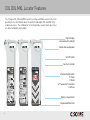
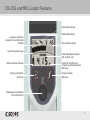
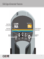
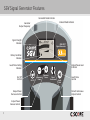
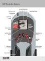
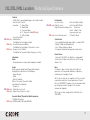
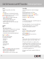
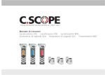
PRECISION PIPE AND CABLE LOCATION
Instruction Manual
CXL Locator DXL Locator MXL Locator
SGA Signal Generator SGV Signal Generator MXT Transmitter
AS
Cable Avoidance Tool
AS
AS
Depth Measuring
Cable Avoidance Tool
Precision Pipe & Cable Locator
cscopelocators.com
cscopelocators.com
cscopelocators.com
Cable Avoidance Tool
Depth Measuring
Cable Avoidance Tool
Precision Pipe & Cable Locator
WARNINGS
C.Scope Locators detect services radiating a detectable signal.
There may be some services that do not radiate and cannot be located.
ALWAYS
EXCAVATE
WITH CARE
Do not use the equipment outside of the temperature range -10˚C to +50˚C
as the batteries may cease to function adequately.
Geographical conditions such as hills and mountains may effectively screen signals
and prevent a detectable Radio signal.
C.Scope Locators alone will not always locate every service.
Use a Generator or Transmitter wherever possible.
Do not touch the metal of the C.Scope Generator/ Transmitter Crocodile Clips or
of the Plastic Pipe Tracer terminals when in use.
The C.Scope Generator/ Transmitter leads MUST NOT be connected directly to
a live service.
Beware of multiple services. C.Scope Locators will not always indicate services
that are close together or one above the other.
Do not use the equipment in areas where hazardous gases may be present.
Check for underground services before using the Earth Stake.
Always make sure that the Locator and Generator/ Transmitter are set to the same
frequency when used together.
Performance may be impaired by unusually strong electromagnetic fields.
It is recommended that the operation of the Locator and Generator/ Transmitter is regularly checked (see pages 48-51).
2
Contents
Warnings
2
Features
CXL, DXL and MXL
4-5
SGA, SGV and MXT
6-7-8-9
Locator Operating Modes
Using the Transmitter
Depth Measurement
Output Power
20
Line
Frequency
21
Sonde/ Plastic Pipe Tracer
Batteries
22
Direct Connection
23-24
Street Lighting
25
41-42
43
Signal Current Measurement 44-47
Signal Clamp/ Injector
26
Function checks
Power
10
Searching
27
Locators
Radio
11
Tracing
28
Generator/ Transmitter
50
Induction
29
Depth
51
Maintenance/ General symbols
52
All Scan
Generator/ Transmitter
12-13
14
Using the Locator
Searching
48-49
30-31
Multiple Services
32
Inductive Sweep
33
Specifications
Batteries
15
Holding the Locator
16
Pipe Tracing using a Sonde
Searching
17
Sonde Batteries
35-36
Pinpointing
18
Tracing
37-38
Tracing
19
Plastic Pipe Tracer
39-40
34
Locators
53
Generators/ Transmitter
54
Support Services
55
3
CXL DXL MXL Locator Features
The C.Scope CXL, DXL and MXL Locators are Pipe and Cable Locators that can
provide precise information about the position and depth (DXL and MXL only)
of buried services. The combination of locating modes ensures buried services
are detected quickly and reliably.
Digital Display
with automatic backlight
Detachable Loudspeaker
On/ Off Switch
Sensitivity Control
Cable Avoidance Tool
C.SCOPE International Ltd
Kingsnorth Technology Park
Wotton Road
Ashford Kent TN23 6LN
United Kingdom
Tel. +44 (0)1233 629181
Fax +44 (0)1233 645897
[email protected]
cscopelocators.com
5
060086
350661
Basic Operating Instructions
Read the Instruction Manual Before Use
CAUTION
This Locator will find most services that radiate a detectable field. There may be some
services that do not radiate and cannot be found. Once a service is located always
check for others nearby. Multiple services in close proximity can affect the apparent
location of these services.
OK
Replace
Do not leave discharged batteries in the equipment.
WARNING Do not change batteries in confined spaces where gas may be present.
SEARCHING IN POWER (P), RADIO (R) AND ALL SCAN (AS) MODES
1. Turn the Mode Switch to the appropriate mode.
2. Hold in the On/Off trigger. The Locator should emit the audible battery test tone
and the digital display should come on. Check the battery level indicator to confirm
the batteries are usable.
3. Rotate the Sensitivity Control fully clockwise to maximum
setting as indicated by the arrow on the control.
4. Carry out the search using a grid pattern
as shown in the diagram. Walk slowly
and keep the Locator upright at all
times and stationary by your side.
5. As you approach the area in which
there is a signal the Locator will emit
an audible response and show a visual
response on the display.
060086
350678
Read Manual
2. The width of the signal response will
shrink as the sensitivity is reduced. Once
it is reduced enough then a peak response
will be seen on the display as the Locator
is moved back and forth over the service.
3. Mark this peak response position.
TRACING
1. Carefully follow the direction of the signal always holding the Locator at right angles
to the line of the signal. Constantly move the Locator back and forth across the service
as shown in the diagram above to be sure of still being over the peak signal.
2. Stop and mark the position of the signal at regular intervals. As more marks
are recorded the precise direction of the service will become more apparent.
SEARCHING IN GENERATOR (G) MODE
The search pattern used to find the Generator signal is slightly different to that used
on Power, Radio or All Scan Modes.
DIRECT CONNECTION
1. Move a few paces away from where the Generator has been connected to the
service. Turn the Mode Switch to Generator Mode (G) and hold the Locator so that
the side is facing towards the Generator.
2. Adjust the Sensitivity so that the Locator is just showing
a visual response and emitting an audible response.
3. Walk in a COMPLETE circle around the
connection point trying to keep the same distance
from this point at all times. When a signal is
detected, ‘pinpoint’ that signal as shown in the
‘Pinpointing’ section above.
4. Having pinpointed the first signal, do NOT
re adjust the Sensitivity Control but continue with
the circle to see if any other signals are detected.
10 metres
C.SCOPE International Ltd
Kingsnorth Technology Park
Wotton Road
Ashford Kent TN23 6LN
United Kingdom
Tel. +44 (0)1233 629181
Fax +44 (0)1233 645897
[email protected]
cscopelocators.com
Warning
Read Manual
Basic Operating Instructions
Read the Instruction Manual Before Use
CAUTION
This Locator will find most services that radiate a detectable field. There may be some
services that do not radiate and cannot be found. Once a service is located always
check for others nearby. Multiple services in close proximity can affect the apparent
location of these services.
BATTERY CHECK
Switch the Locator on by pulling up on the On/Off trigger
OK
Replace
under the handle. Check for audible tone and the battery
level indicator in the bottom left hand corner of the display.
Replace batteries if necessary.
Do not leave discharged batteries in the equipment.
WARNING Do not change batteries in confined spaces where gas may be present.
SEARCHING IN POWER (P), RADIO (R) AND ALL SCAN (AS) MODES
1. Turn the Mode Switch to the appropriate mode.
2. Hold in the On/Off trigger. The Locator should emit the audible battery test tone
and the digital display should come on. Check the battery level indicator to confirm
the batteries are usable.
3. Rotate the Sensitivity Control fully clockwise to maximum
setting as indicated by the arrow on the control.
4. Carry out the search using a grid pattern as shown
in the diagram. Walk slowly and keep the Locator
upright at all times and stationary by your side.
5. As you approach the area in which there
is a signal the Locator will emit an audible
response and show a visual response
on the display.
PINPOINTING
1. Walk through the area of the signal
response. If the visual response goes up
off the scale reduce the sensitivity slightly.
2. The width of the signal response will
shrink as the sensitivity is reduced. Once
it is reduced enough then a peak response
will be seen on the display as the Locator
is moved back and forth over the service.
3. Mark this peak response position.
PINPOINTING
1. Walk through the area of the signal
response. If the visual response goes up
off the scale reduce the sensitivity slightly.
INDUCTION
Searching in induction mode is the same as for
direct connection except that the search is in a
straight line across the end of the Generator
and at least 10 metres away.
5
Warning
Read Manual
Warning
BATTERY CHECK
Switch the Locator on by pulling up on the On/Off trigger
under the handle. Check for audible tone and the battery
level indicator in the bottom left hand corner of the display.
Replace batteries if necessary.
Depth Measuring
Cable Avoidance Tool
C.SCOPE International Ltd
Kingsnorth Technology Park
Wotton Road
Ashford Kent TN23 6LN
United Kingdom
Tel. +44 (0)1233 629181
Fax +44 (0)1233 645897
[email protected]
cscopelocators.com
TRACING
1. Carefully follow the direction of the signal always holding the Locator at right angles
to the line of the signal. Constantly move the Locator back and forth across the service
as shown in the diagram above to be sure of still being over the peak signal.
2. Stop and mark the position of the signal at regular intervals. As more marks are recorded
the precise direction of the service will become more apparent.
SEARCHING IN GENERATOR (G) MODE
The search pattern used to find the Generator signal is slightly different to that used
on Power, Radio or All Scan Modes.
DIRECT CONNECTION
1. Move a few paces away from where the Generator has been connected to the
service. Turn the Mode Switch to Generator Mode (G) and hold the Locator so that
the side is facing towards the Generator.
2. Adjust the Sensitivity so that the Locator is just showing
a visual response and emitting an audible response.
3. Walk in a COMPLETE circle around the connection
point trying to keep the same distance from this point
at all times. When a signal is detected, ‘pinpoint’ that
signal as shown in the ‘Pinpointing’ section above.
4. Having pinpointed the first signal, do NOT re adjust
the Sensitivity Control but continue with the circle to
see if any other signals are detected.
INDUCTION
Searching in induction mode is the same as for direct connection
except that the search is in a straight line across the end of the
Generator and at least 10 metres away.
10 metres
DEPTH MEASUREMENT WITH A GENERATOR
1. The Generator should be set to ‘Continuous’ and is best in Connected Mode.
2. Set the Locator to Generator Mode. Rest the Locator on the ground above and AT RIGHT
ANGLES TO the line of the service.
3. Press and hold down the depth button. The depth will be shown in metres.
DEPTH MEASUREMENT WITH A SONDE
1. Carefully pinpoint the EXACT position of the Sonde.
2. Rest the Locator on the ground above and IN LINE WITH the Sonde.
3. Push the depth button TWICE and hold on the second push. ‘SONDE’ will flash on the
display and the depth will then be shown in metres.
Precision Pipe & Cable Locator
4 Position Mode Switch
P: Power
R: Radio
G/T: Generator/ Transmitter
A: AllScan
Battery Compartment
Replaceable Wear Foot
4
CXL DXL and MXL Locator Features
Power Mode Indicator
Frequency Selected in
Generator/ Transmitter Mode
Indicator
Radio Mode Indicator
AllScan Mode Indicator
Signal Strength Bar Graph
Sonde Depth Mode Indicator
(DXL and MXL only)
Battery Condition Indicator
Signal Current Button
(MXL only)
Depth (DXL and MXL only)
or Signal Current Measurement
(MXL only)
Frequency Button
(MXL only)
Depth Measurement Button
(DXL and MXL only)
5
SGA / SGV Signal Generator and MXT Transmitter Features
The C.Scope SGA and SGV Signal Generators are an ideal
accompaniment to the CXL and DXL Locators.
The SGA has the facility of high and low output power and
can operate with a pulsed or continuous output signal.
The SGV Signal Generator in addition has a display
showing the battery condition and power output indication.
The SGV also has variable levels of output power that can
be selected by the user.
The C.Scope MXT Transmitter is an ideal accompaniment
to the MXL Locator.
The range of operating frequencies and adjustable power
output is designed to make the MXL and MXT combination
an extremely versatile Pipe and Cable Locator that can
tackle many varied locating tasks.
Auxiliary Earth Lead Socket
Direct Connection Socket
Auxiliary 10m Earth Lead
Crocodile Clips
Connection Magnets
Batteries
Accessory Tray
Accessory Tray Holding Clips
Earth Stake
6
SGA Signal Generator Features
Signal Generator
Output Power
Increase Control
Output Power
Decrease Control
Pulsed/ Continuous
Output Control
On/ Off
Control
On/ Off
Low
Power
High
Power
Loud/ Mute
Control
Pulse /
Continuous
Audio
Mute
7
SGV Signal Generator Features
Connected Mode Indicator
Induced Mode Indicator
Generator
Output Frequency
Signal Strength
Indicator
ONE WATT
Signal Generator
Battery Condition
Indicator
Output Power Level
Indicator
Loud/ Mute Setting
Indicator
On/ Off
Control
Output Power
Decrease Control
Output Power
Increase Control
8
On/ Off
Decrease
Power
Increase
Power
Pulse /
Continuous
Audio
Mute
Loud/ Mute
Control
Pulsed/ Continuous
Output Control
MXT Transmitter Features
Connected Mode Indicator
Selected Transmitter
Output Frequency
Induced Mode Indicator
Signal Strength
Indicator
Battery Condition
Indicator
Loud/ Mute Setting
Indicator
On/ Off
Control
Output Power
Level Control
Output Power Level
Indicator
Loud/ Mute
Control
Pulsed/ Continuous
Output Control
Frequency Control
9
Locator Operating Modes: Power Mode
In Power Mode the Locator detects power signals.
These power signals are present on all current carrying
electricity cables although not all are detectable. Power
signals may also flow along other conductors such as
metal gas and water pipes, telecom cables, metal fences
and railway tracks.
Limitations of Power Mode
Not all electricity cables can be found using the Power
Mode. Here are the most important examples of
electricity cables that may not be detectable in the
Power Mode:
Street lighting cables. When the lights are off, no
current flows and so no power signal is created.
Supplies to buildings or plant using very little or no
electricity may not have a detectable power signal.
Pot-ended or capped cables. These will never have any
current flowing through them but are possibly still live.
Disused or abandoned cables.
A few high voltage electricity cables. These can be
“well balanced”, electrically and therefore radiate little
or no power signal.
Direct Current cables (such as those found on railway
systems). These do not create their own power signals.
Cables more than 3 metres deep.
WARNING Locators can only detect services radiating a detectable electromagnetic signal.
There may be some services that do not radiate these signals and cannot be located.
WARNING Absence of a power signal does not mean the service is not live.
NOTE Generally these services should be detectable using the Radio or Generator/ Transmitter Modes.
10
Locator Operating Modes: Radio Mode
In Radio Mode, the Locator detects signals from various
radio transmitters. These signals flow through the
ground and will tend to follow the line of least resistance
such as a buried metallic service. When this happens
the service can often be detected by using the Locator
in Radio Mode.
Limitations of Radio Mode
Not all services will be detectable in Radio Mode.
A strong radio signal present on one service may
be masking a weaker radio signal present on an
adjacent service.
It is not normally possible to determine what the
service is in Radio Mode, only it’s position.
Radio signals do not favour one utility over another.
The depth of the buried service CANNOT be judged
by the strength of the radio signal alone.
Normally it is only possible to detect radio signals
present on services up to 2 metres deep.
A short service may not have enough signal to
be detected.
WARNING Locators can only detect services radiating a detectable electromagnetic signal.
There may be some services that do not radiate these signals and cannot be located.
NOTE Most buried metallic services not found in Radio Mode should be detectable by using Generator
Mode with the Generator or Transmitter Mode with the Transmitter.
11
Locator Operating Modes: All Scan Mode
In All Scan Mode, the Locator detects at ALL frequencies
in the range of 50Hz to 33kHz. Sometimes a signal that
is outside of the frequency range of the other search
modes (Power, Radio, and Generator/ Transmitter) will
be present on a buried metallic service. All Scan Mode
is a useful additional search mode to employ as it may
detect these ‘extra’ signals as well as the Power, Radio
and Generator/ Transmitter signals.
12
Locator Operating Modes: All Scan Mode
Limitations of All Scan Mode
All Scan Mode has exactly the same limitations as those
listed for the Power and Radio Modes:
Street lighting cables when the lights are switched off,
supply cables to buildings or plant using little or no
electricity, pot-ended or capped cables, well balanced
high voltage cables and direct current cables may all be
missed on the All Scan Mode.
A strong All Scan signal present on one service may mask
a weaker All Scan signal present on an adjacent service.
It is not normally possible to determine what the service
is in All Scan Mode, only its position.
All Scan signals do not favour one utility over another.
The depth of the buried service CANNOT be judged by
the strength of the All Scan signal alone.
Normally it is only possible to detect All Scan signals
present on services up to 2 metres deep.
A short service may not have enough signal to be detected.
WARNING Using the Power and Radio Modes may be more effective in areas where there are many services
radiating an All Scan signal.
13
Locator Operating Modes: Generator/ Transmitter Mode
In Generator/ Transmitter Mode the Locator detects conductors
radiating a signal applied by the Generator/ Transmitter.
The Generator/ Transmitter provides a means of applying a known
signal to buried metallic services which can then be detected using
the Locator.
Direct Connection
By detecting this signal it is possible to locate, trace and identify the
pipes or cables that may be carrying it.
There are TWO basic methods by which the Transmitter/ Generator
signal can be applied to buried services:
Direct Connection - The Generator/ Transmitter is attached
directly to the service using either the Direct Connection Leads
or one of the accessories available for use with the Generator/
Transmitter such as the Signal Clamp or Signal Injector. A 33kHz,
8kHz or 640/512Hz frequency signal is then applied to the service
(640/512Hz via connection leads only). 8kHz and 640/512Hz are only
available on the MXL/ MXT.
Induction - The Generator/ Transmitter can induce a signal onto a
buried metallic service remotely from the surface without the need
to physically connect to that service. A 33kHz or 8kHz (MXT
Transmitter only) signal is used.
Limitations of Generator Mode/ Transmitter Mode are covered in
‘Using the Generator/ Transmitter’ section of this manual along
with guidance on which frequency to use (MXT Transmitter only).
WARNING Locators can only detect services radiating a detectable electromagnetic signal.
There may be some services that do not radiate these signals and cannot be located.
14
Induction
Using the Locator: Batteries
Locator Battery Check
Switch the Locator on by pulling up on the On/Off trigger
positioned on the underside of the handle. The Locator
should emit a clear audible battery check tone for one
second and the display should come on.
Check the battery level indicator in the bottom left hand
corner of the display. If there is only one segment or no
segments of the indicator filled in then the batteries will
need to be renewed before locating work can begin.
Changing Locator Batteries
Push the two clips back to release the battery
compartment door. Remove ALL EIGHT used batteries
and replace with new ones. Be careful to insert the new
batteries the correct way round in the holder. Replace the
holder in the battery compartment making sure that the
two terminals on the holder make contact with the two
terminals within the battery compartment. Close the
battery compartment door securely.
Battery Levels
OK
replace
batteries
NOTE A spare battery pack can be carried inside the battery compartment.
NOTE Only use alkaline AA (LR6) size batteries. Dispose of the used batteries safely in accordance with
local regulations.
WARNING Do not change batteries in confined spaces where gas may be present.
15
Using the Locator: Holding the Locator
When in use the Locator should always be held upright.
NEVER swing the Locator such that it moves away from
the vertical.
incorrect
Your index finger will then be free to adjust the
Sensitivity Control.
correct
90O
16
Your middle or little finger should be used to squeeze,
and hold on, the On/Off trigger.
cscopelocators.com
Using the Locator: Searching
There are three stages to the locating process; searching,
pinpointing and tracing
1. Turn the Mode Switch to the appropriate mode.
2. Hold in the On/Off trigger. The Locator should emit the audible
battery test tone and the digital display should come on. Check
the battery level indicator to confirm the batteries are usable.
3. Rotate the Sensitivity Control fully clockwise to its maximum
setting as indicated by the arrow on the control.
cscopelocators.com
4. Carry out the search using a grid pattern as shown in the
diagram. Walk slowly and keep the Locator upright at all times
and stationary by your side.
5. As you approach the area in which there is a signal the
Locator will emit an audible response and show a visual
response on the display.
Search Grid Pattern
6. Keep walking until the audible and visual responses disappear.
NOTE This search technique applies only to the
Power, Radio and All Scan modes. See ‘Using the
Generator/ Transmitter’ for the correct search pattern
when using Generator/ Transmitter Mode.
NOTE Sometimes the Locator will give an audible
response and strong (full scale) visual response across
the whole of the search area. In this case turn the sensitivity
down slightly and repeat the search using the same grid pattern.
17
Using the Locator: Pinpointing
Having found a signal the next step is to pinpoint the source.
The closer the Locator is to the signal source the stronger
the response.
To Pinpoint a Signal
1. Keeping the Locator vertical, walk through the area of the
signal response. If the visual response goes up off the scale
then stop and reduce the sensitivity of the Locator slightly
before continuing.
2. The width of the signal response will shrink as the
sensitivity is reduced. Once it is reduced enough then a
clear peak response will be seen on the display as the
Locator traverses the service. The Locator is positioned
directly above the buried service when the display is at its
highest (peak) reading.
3. Carefully rotate the Locator over the peak reading until the
visual response falls to a minimum. The Locator will now be
roughly IN LINE with the direction of the buried service.
4. Mark the position of the buried service.
NOTE The amount of sensitivity adjustment needed to pinpoint a service can vary depending on the mode being
used, the signal strength and the service depth.
18
Using the Locator: Tracing
Having pinpointed a service it should now be possible to trace its route.
1. Carefully follow the direction of the signal holding the Locator at right angles
to the line of the signal. It is necessary to constantly ‘slice’ the Locator from side
to side in order to be sure of still being over the peak signal response.
2. Stop and mark the position of the signal at regular intervals. As more marks
are recorded the precise direction of the service will become more apparent.
NOTE It may be necessary to readjust the sensitivity to maintain the
optimum response.
NOTE After tracing, return to the original search grid to search for
further buried services.
WARNING Never rush the tracing process. Small and unexpected changes in the service’s route will be
missed if care is not taken to follow the signal’s path every step of the way.
Lost Signals
This can be because of a curve, or bend in the route, change in depth of the
service, a T connection or the end of the service.
Finding Lost Signals
1. Locate in a circle at least 1 metre around the point where the signal was lost.
This should locate the service if it has simply changed direction sharply or T’d
into another service.
2. If you find nothing then increase the sensitivity and repeat the circle.
This should find the service if it has continued but at a greater depth.
19
Using the Generator/ Transmitter:
Output Power Level and Pulse/ Continuous Output
Output Power Level
The SGV Generator and the MXT Transmitter have four, selectable output
power levels. The SGA Generator has two selectable output power levels.
For long distance tracing or for detecting deep services it is always best to
use the highest power setting of the Generator/ Transmitter. Please note
that higher power settings will drain the batteries more quickly than lower
power settings.
For tracing work close to the signal application point, especially when using
Induction Mode, the lower power settings are better.
NOTE When using accessories such as Signal Clamps, Signal Injectors and Plastic Pipe Tracers it is normally
best to use the highest power setting.
Pulsed/ Continuous Output
For most locating work a Continuous signal output is best and MUST
be used for any Depth or Signal Current Measurements.
A Pulsed signal output can be useful when it has become difficult
to distinguish the Generator/ Transmitter signal from unwanted
interference, for example, when tracing services over long distances
or at greater depths.
NOTE The 640/512Hz signal can only be applied as a Continuous signal and by using the Direct Connection Leads
(MXT Transmitter only).
20
Using the Transmitter: Which Frequency Signal to use
(MXT Transmitter only)
Generally, 33kHz is the best frequency to use as it performs well in
all applications. The lower frequency signals (8kHz and 640/512Hz)
should travel further along a metallic service than the higher
frequency signal (33kHz) although they may be more difficult
to successfully apply in the first place. There should also be less
‘coupling’ of these signals onto adjacent services.
There are exceptions to this general rule and so the best option is
to try each frequency and then utilise the one that is giving the best
results for that particular service. This is irrespective of the method
of signal application; Direct Connection, Signal Clamp, Signal Injector
or Induction Mode, and of the service being traced.
NOTE The 640/512Hz frequency signal can only be applied using the Direct Connection Leads and with a
Continuous signal output.
WARNING The Locator frequency MUST always be set to the same frequency as the Transmitter.
21
Using the Generator/ Transmitter: Batteries
Battery Check
Switch the Generator/ Transmitter on by pressing the On/Off switch. The Generator/ Transmitter should emit a loud
continuous tone or a regular pulsed tone. If the batteries need replacing an interrupted tone will be heard.
During use, the Generator/ Transmitter will also warn the Locator user of low battery status
by altering its normal continuous or pulsed signal output to a distinct interrupted signal output.
(SGV Generator and MXT Transmitter only:
Check the Battery Level Indicator in the bottom left hand corner of the
display. If there is only one segment or no segments of the indicator filled in
then the batteries will need to be renewed before locating work can begin.)
SGV Generator and MXT Transmitter only
Changing the Batteries
Remove the Accessory Tray.
Undo the two round, knurled retaining screws situated on the
underside of the Generator/ Transmitter holding the Battery Cover.
Remove ALL FOUR used batteries and replace with new ones.
Be careful to insert the new batteries the correct way round in
the compartment as indicated on the case.
Replace the Battery Cover being careful to not over tighten the
retaining screws.
Replace the Accessory Tray.
Battery Levels
OK
NOTE Dispose of the used batteries safely in accordance with local regulations.
NOTE Only use alkaline D (LR20) size batteries
WARNING Do not change batteries in confined spaces where gas may be present.
22
replace
batteries
Using the Generator/ Transmitter: Direct Connection
WARNING Never connect directly to electrical services.
WARNING You may need to seek permission from the service owners before connecting on to some buried services.
The Direct Connection Leads and Earth Stake that are
supplied with the Generator/ Transmitter are used to apply
a signal to any metal pipe at a suitable access point such
as a valve, hydrant point, stop cock or exposed pipe length.
1.
2.
1. Plug the Direct Connection Leads into the Generator/
Transmitter connection socket.
2. Attach the red lead to the pipe at your point of access
using the Crocodile Clip. Ensure that you have a secure
and clean grip on the pipe with the Crocodile Clip.
3. Turn the Generator/ Transmitter on and set Output
Power Level to the lowest level.
(MXT Transmitter only: Select the frequency to be used;
33kHz, 8kHz or 640/512Hz).
4. Place the Earth Stake in the ground (having first
searched the area for buried cables with the Locator).
The ideal position for the Earth Stake is at right angles to
the assumed line of the pipe and the full length of the
Direct Connection Leads away from the pipe access point.
NOTE The type of metal that the pipe is constructed from or it’s use will have little effect on its traceability.
NOTE If it is not possible to get the Crocodile Clip to grip the pipe then use the Magnet supplied.
NOTE MXT Transmitter only: When turning on, the Transmitter will return to the last Output Power, Frequency,
Pulsed/Continuous and Loud/Mute settings that were used.
WARNING Do not handle the bare Crocodile Clips when the Generator/ Transmitter is switched on.
23
Using the Generator/ Transmitter: Direct Connection
5. Connect the black Earth Lead to the Earth Stake (or the
alternative earth point). If your earth point is too far away from
the pipe access point for the black Earth Lead to reach then use
the yellow 10 metre Auxiliary Earth Lead instead.
6. As the Earth Lead is connected to the Earth Stake the audible
signal from the Generator/ Transmitter should change in pitch.
The lower the pitch, then the better the signal will be on the
metal pipe.
If there is no change of tone it may be that some dirt, rust
or paint on the pipe is preventing the Direct Connection Lead
from making a good contact with the pipe. Alternatively it may
be that your earth point is at fault. Change the position of the
Earth Stake or use an alternative earth point.
(SGV Generator and MXT Transmitter only:
There will also be a visual representation of the quality of the
connection in addition to the audible pitch change. The greater
the response on the display then the better the signal will be
on the pipe).
7. Adjust the Output Power Level to suit.
NOTE If it is not possible to use the Earth Stake use a nearby metal fence post, manhole cover or gully cover.
DO NOT use something that may have another metallic service attached to it, such as a metal street lighting column.
NOTE If the Generator/ Transmitter pitch does not change then there is no signal being transferred onto the service.
24
Using the Generator/ Transmitter: Street Lighting
Direct Connection to a Street Lighting Column
The position and route of street lighting or car park lighting
cables can be determined by using a Generator/ Transmitter
and the pipe connection method.
Follow the same rules as for connecting the Generator/
Transmitter to a metal pipe except attach the red Direct
Connection Lead to the OUTSIDE of the lamp column.
WARNING NEVER open the lamp column door to gain access to the cables, this is potentially dangerous
and is not necessary.
NOTE Make sure that the Direct Connection Crocodile Clip is not insulated from the metal of the column by paint.
NOTE If the column is concrete attach the Crocodile Clip to the metal surround of the access door.
25
Using the Generator/ Transmitter: Signal Clamp/ Injector
Signal Clamp
1. Plug the Signal Clamp into the connection socket on the Generator/ Transmitter.
2. Turn the Generator/ Transmitter on (and select either 33kHz or 8kHz on the Transmitter).
3. Check that the jaws of the Signal Clamp are clean. Place the Signal Clamp AROUND the cable
making sure that the jaws are able to fully close. The audible signal from the Generator/ Transmitter
should drop in pitch indicating that the clamp jaws have closed correctly and the response on the
display (if fitted) should increase.
WARNING NEVER attempt to place the Signal Clamp around electricity cables
that are deliberately suspended out of reach. They may be unsheathed or unprotected cables.
NOTE The Signal Clamp cannot apply a signal to a cable that is not earthed at both ends such as abandoned
cables that have been cut off where they appear above ground or cables supplying unearthed equipment.
Signal Injector
1. Plug the Signal Injector into the connection socket on the Generator/ Transmitter and an electric outlet.
2. Turn the Generator/ Transmitter on (and select either 33kHz or 8kHz on the Transmitter).
3. Turn the socket on. The audible tone from the Generator/ Transmitter will drop in pitch to indicate a
successful connection and the visual response on the display (if fitted) should go to full scale.
NOTE On two wire Protective Multiple Earth (PME) systems it may be necessary to also
provide an external earth using the yellow 10 metre Auxiliary Earth Lead and Earth Stake.
NOTE Always check with the owners that it is acceptable to interrupt the supply before connecting the Signal Injector.
NOTE Using the Signal Injector may cause the system protection to trip.
WARNING DO NOT use the Signal Injector on systems with voltages in excess of 240 volts AC.
Domestic systems will normally be below this voltage.
26
Generator/ Transmitter:
Searching for the Direct Connected Signal
The search pattern used to find the Generator/ Transmitter signal
when applied by a direct connection method (Direct Connection
Leads, Signal Clamp or Signal Injector) is different to the normal
search pattern used on Power, Radio or All Scan Modes.
1. Move a few paces away from where the Generator/ Transmitter
has been connected to the service. Turn the Mode Switch to
Generator Mode or Transmitter Mode. Press the Frequency Button
(MXL Locator only) to select the same frequency as being transmitted
by the Generator/ Transmitter. Hold the Locator so that the side of
the Locator is facing towards the Generator/ Transmitter.
2. Adjust the sensitivity so that the Locator is just showing a visual
response and just emitting an audible response.
3. If possible walk in a COMPLETE circle around the connection point
trying to keep the same distance from this point at all times. When a
signal is detected, ‘pinpoint’ that signal as shown in the ‘Using the
Locator’ section.
4. Having pinpointed the first signal, do NOT readjust the Sensitivity
Control but continue with the circle to see if any other signals are
detected. If more signals are detected compare the strength of each
signal by observing the bar display. The strongest signal will usually
be coming from the service that the Generator/ Transmitter is
connected to.
27
Generator/ Transmitter: Tracing the Direct Connected Signal
The tracing technique used to follow the Generator/
Transmitter signal when applied by a direct connection
method (Direct Connection Leads, Signal Clamp or Signal
Injector) is almost exactly the same as the normal tracing
technique used on Power, Radio or All Scan Modes but with
the following differences:
The signal that the Locator is detecting will get weaker
the further away from the Generator/ Transmitter that
you go. It will be necessary to regularly adjust (increase)
the Locator Sensitivity Control to compensate for this.
MXT Transmitter only:
Having traced the signal for a short distance it may be
worthwhile switching the MXT Transmitter to the
alternative frequencies to see if they give a stronger
response. Choose the frequency that gives the strongest
response and continue with the trace.
NOTE It is not possible to search for the signal above any leads connecting the Generator/ Transmitter
to the service or above the Earth Lead connected to the Earth Stake.
28
Generator/ Transmitter: Induction
This is the standard method for inducing signals onto
buried metallic services. It produces a strong signal
directly below the Generator/ Transmitter but the
signal strength drops off quite quickly either side
of the Generator/ Transmitter.
1. Check that there are no accessories plugged into
the Connection Socket. The Generator/ Transmitter
switches automatically to Induction Mode when the
socket is unused.
2. Place the Generator/ Transmitter UPRIGHT on the
ground where you suspect services may be buried and
IN LINE with the expected route of these services.
3. Turn the Generator/ Transmitter on (and with the MXT
Transmitter select either 33kHz or 8kHz) then check that
the batteries are OK.
4. The signal will be radiated into the ground immediately
below and for approximately 3 metres either side of the
Generator/ Transmitter.
NOTE The closer the Generator/ Transmitter is to the position of the buried service then the
stronger the signal will be on that service.
NOTE MXT Transmitter only: Normally the 33kHz signal is more effective on Induction Mode,
particularly on short length or small diameter services.
NOTE MXT Transmitter only: It is not possible to apply a 640/512Hz signal by Induction Mode.
29
Generator/ Transmitter: Searching for an Induced Signal
The search pattern used to find the Generator/ Transmitter
signal when applied by Induction Mode is slightly different
to the search pattern used on other modes.
1. Move AT LEAST 10 metres away from the Generator/
Transmitter position with your Locator. This is to avoid the
Locator picking up the airborne signal rather than the signal
induced onto the buried service.
2. Stand so that you are roughly in line with the end of
the Generator/ Transmitter and hold the Locator so that
the side of the Locator is facing towards the Generator/
Transmitter.
10m
3. Select Generator Mode or Transmitter Mode.
(The MXL Locator must be set to the same frequency as the
MXT Transmitter).
4. Adjust the sensitivity so that the Locator is JUST showing
a visual response and emitting an audible response.
NOTE A Generator/ Transmitter will transmit a significant amount of signal into the air as well as into the ground.
Make sure you keep the Locator upright at all times to reduce the risk of picking up the airborne signal.
30
Generator/ Transmitter: Searching for an Induced Signal
5. Walk in a straight line across the end line of the
Generator/ Transmitter. When a signal is detected
‘pinpoint’ that signal as shown in the ‘Using the Locator’
section. If no signal is found move the Generator/
Transmitter 5 metres and try again. Continue this
procedure moving the Generator/ Transmitter in five metre
steps, following a grid pattern, until a signal can be found.
10m
6. It may be possible to increase the strength of the
induced signal on the buried service by improving the
positioning of the Generator/ Transmitter. Once the buried
service has been pinpointed, moving the position of the
Generator/ Transmitter from side to side will give an
increase or decrease in the Locator response. Remember,
the closer the Generator/ Transmitter is to the position of
the buried service then the stronger the signal will be on
that service.
NOTE The Generator/ Transmitter signal that the Locator is detecting will get weaker the further away
from the Generator/ Transmitter that you go. It will be necessary to regularly adjust (increase) the
sensitivity to compensate for this.
31
Generator/ Transmitter: Induction; Multiple Services
It is important to check for the presence of adjacent services running
close, or parallel, to the service that you have already located.
1. Check that there are no accessories plugged into the Connection Socket.
2. Turn the Generator/ Transmitter on and check that the batteries are OK.
3. Place the Generator/ Transmitter on the ground ON ITS SIDE over the previously
located service so that you are no longer inducing a signal onto that service.
0%
4. Re-scan the area looking for another peak signal close to where the original
signal was found. This operation should be repeated until you are satisfied that
no further services can be located.
50%
1m
30%
1m
NOTE This method can also be used to ‘mask’ one service so that another can be found.
NOTE The signal will be radiated up to 3 metres either side of the Generator/ Transmitter but NOT directly below
when the Generator/ Transmitter is on its side.
Limitations of Induction Method - There are limitations concerning what can be achieved when using a Generator/
Transmitter on the Induction Mode compared to the Connected Mode.
It is not normally possible to identify what the service is that has been detected with an induced signal. If the signal can
be followed far enough, a visible feature such as a valve cover or cable pit cover may be found that can indicate the
identity of the service.
Cables with a very small cross section may not have enough signal induced onto them to make them detectable. It is
often not possible to apply an induced signal onto just ONE specific buried service, in order to trace it alone, when other
services are positioned in a close proximity.
NOTE An induced signal cannot be applied to a buried service that lies beneath reinforced concrete. The reinforcing
bars will re-radiate the induced signal masking any signal that has been induced onto the buried service below.
32
Generator/ Transmitter: Using an Inductive Sweep
If a large area needs to be searched for buried services
then an ‘Inductive Sweep’ could be used. It is an ideal
method for detecting the position of buried services as
they cross the boundary of a large site.
An Inductive Sweep requires two people; one to operate
the Locator and one to position the Generator/ Transmitter.
5. Immediately tell your colleague to stop and place the
Generator/ Transmitter on the ground at that point.
Now you can pinpoint the service and trace out its route.
Continue the sweep across the length and width of
search area.
1. Stand about 10 metres apart.
2. The first person holds the Generator/ Transmitter,
switched on at the lowest Output Power Level, close to
the ground and ‘end on’ (see diagram) whilst you hold
the Locator switched to Generator Mode or Transmitter
Mode. (The MXL Locator must be set to the same
frequency as the MXT Transmitter).
3. Adjust the sensitivity so that the Locator is just showing
a visual response and emitting an audible response.
4. Together, slowly walk across the site, staying the same
distance apart and being careful to keep in line with each
other. When the Generator/ Transmitter gets close to a
buried metallic service the signal will be induced onto
it and you should see this in the increased response on
the Locator.
NOTE It is important to maintain the same distance and between the Locator
and Generator/ Transmitter at all times.
33
Pipe Tracing using a Sonde
Non-metallic pipes such as sewers or drains, service
ducts, plastic gas and water pipes are not electrically
conductive and so will not be detectable using a Locator
on the Power, Radio or All Scan Modes. It is also
impossible to apply a detectable Generator/ Transmitter
signal to the non-metallic pipe or, for that matter, to the
water or gas within that pipe.
If access can be gained into these pipes then a C.Scope
Sonde or Plastic Pipe Tracer should make it possible to
determine their position and route.
The 33kHz and 8kHz General Purpose Sondes can be
used in pipes as small as 50mm in diameter and up to
seven metres deep.
The 33kHz Duct Sonde can be used in pipes as small
as 30mm in diameter and up to five metres deep.
C.Scope are continually developing Sondes for specific
applications. Keep abreast of our latest products via
our website www.cscopelocators.com or your local
distributor.
Sondes
C.Scope Sondes are small, battery powered, waterproof,
33kHz or 8kHz transmitters that can be inserted into pipes
such as a sewer, drain or cable duct. Their position can be
pinpointed (and therefore the location of the pipe)
by using the Locator switched to Generator Mode/
Transmitter Mode.
The Sonde is inserted into and then moved along
the pipe to the point at which the pipe needs to be
located. This is normally done by fitting the Sonde
to drain rods. Alternatively, the Sonde can be attached
to a continuous fibreglass duct rodder, jetter hose or
camera inspection system.
NOTE A 33kHz or 8kHz Sonde will NOT transmit a signal through a metal pipe.
34
Pipe Tracing using a Sonde: Batteries
General Purpose Sonde
The General Purpose Sonde is supplied in two frequencies;
33kHz (orange casing) or 8kHz (green casing) and is
powered by a single AA (LR6) size alkaline battery. The
8kHz Sonde will only function with the MXL Locator.
+
----
1. To turn the Sonde on, separate the two halves of the
Sonde casing. Insert a new battery into the battery
compartment with the positive end down.
2. Screw the two halves of the Sonde together being
careful not to over tighten them. The Sonde is now
transmitting a signal.
3. To turn the Sonde off the battery must be removed
or reversed.
NOTE Only use alkaline batteries. Dispose of the used battery safely in accordance with local regulations.
NOTE Always use a new battery in a Sonde if you expect to take a long time to trace the pipe or duct route.
WARNING The Locator frequency MUST always be set to the same frequency as the Sonde.
35
Pipe Tracing using a Sonde: Batteries
Duct Sonde
The Duct Sonde is supplied at 33kHz only (yellow casing)
and is powered by a single AAA (LR03) size alkaline battery.
1. To turn the Duct Sonde on, use a large flat bladed
screwdriver to unscrew the battery cover located within
the hollow end of the Sonde casing. Insert a new battery
into the battery compartment with the positive end down.
2. Replace the battery cover fully using the screwdriver to
secure. The Duct Sonde is now transmitting a signal.
3. To turn the Sonde off the battery must be removed.
+
----
NOTE Only use alkaline batteries. Dispose of the used battery safely in accordance with local regulations.
NOTE Always use a new battery in a Sonde if you expect to take a long time to trace the pipe or duct route.
WARNING The Locator frequency MUST always be set to the same frequency as the Sonde.
36
Pipe Tracing using a Sonde: Tracing a Sonde
The technique used to determine the position of a Sonde is always
the same irrespective of which Sonde is being used.
Before inserting the Sonde into the pipe it is best to set up the
Locator so that the sensitivity is correctly adjusted to suit the pipe
depth. This is easier to do when the Sonde is visible at the bottom
of the manhole rather than already in the pipe.
1. The blade of the Locator must be held IN LINE with the Sonde
at all times.
NOTE This is at 90 degrees to the way in which the Locator is held for most other locating tasks.
2. Turn the Locator to Generator Mode/ Transmitter Mode, switch
on (and on the MXT Transmitter select the correct frequency).
Check the Battery Level Indicator to confirm the Locator batteries
are usable. Replace if necessary.
37
Pipe Tracing using a Sonde: Tracing a Sonde
3. Keeping the blade of the Locator in line with the Sonde,
move the Locator backwards and forwards over the length
of the Sonde. Adjust the sensitivity until a clear peak
response is shown on the display as the Locator passes
directly over the position of the Sonde.
3./ 4.
4. Move the Locator from side to side over the position of
the Sonde. A similar peak response should be seen on the
display as the Locator passes directly over the position of
the Sonde.
The Locator is now set up ready for tracing the Sonde.
5. Push the Sonde up the pipe.
6. With the Locator turned on, walk from the pipe access
point in the direction that the Sonde was pushed. A strong
peak signal directly over the Sonde should be detected with
two lesser “ghost” signals found either side of the Sonde’s
true position. These ghost signals are always weaker than
the main signal and should not be mistaken for the true
Sonde signal.
6.
7. Pinpoint the Sonde position by moving the Locator back
and forth and from side to side to get the peak response.
8. Push the Sonde further up the pipe and repeat the
pinpointing process.
See page 43 for Depth Measurement using a Sonde.
38
Non-Metallic Pipe Tracing: Plastic Pipe Tracer
Line Tracing
The Plastic Pipe Tracers can be used in services up to 3 metres deep (Locator
dependent) on line tracing mode and do not work through metal pipes or ducts.
The Plastic Pipe Tracer needs to be inserted into the pipe before a signal from
the Generator/ Transmitter is applied to the length of the Tracer.
The 33kHz Generator/ Transmitter signal is applied using the ‘Direct Connection
to a metal pipe’ method as shown on page 23-24 of this manual. Only one lead is
connected to the Plastic Pipe Tracer, the other is connected to an Earth Stake.
WARNING Authorisation may be required before using the Plastic Pipe Tracer on some services.
WARNING DO NOT touch the metal of the Crocodile Clips or the terminals of the Plastic Pipe Tracer
when using the Generator/ Transmitter.
NOTE It is important that a change of pitch is heard when making the connections to ensure that there is a
detectable signal present on the Tracer.
NOTE The Generator/ Transmitter signal is unlikely to travel the entire length of the Tracer within the pipe.
Never assume that you have located the end of the Tracer on Line Tracing Mode. Use End Tracing if required.
39
Non-Metallic Pipe Tracing: Plastic Pipe Tracer
End Tracing
The very tip of the Plastic Pipe Tracer can be energised with the signal from a Generator/ Transmitter.
It is acting much like a Sonde and offers a very reliable way of pinpointing the position of the tip.
A 33kHz Generator/ Transmitter signal is applied by connecting the red Direct Connection Lead to one of the
terminals on the Tracer and the black Earth Lead to the other terminal. As the second connection is made a
change of pitch should be heard from the Generator/ Transmitter signal indicating successful connection.
The tip of the Plastic Pipe Tracer is then pinpointed using the same technique as for Sonde tracing with the
Locator blade in line with the Tracer.
WARNING Authorisation may be required before using the Plastic Pipe Tracer on some services.
WARNING DO NOT touch the metal of the Crocodile Clips or the terminals of the Plastic Pipe Tracer
when using the Generator/ Transmitter.
NOTE It is important that a change of pitch is heard when making the connections to ensure that there is a
detectable signal present on the Tracer.
NOTE End tracing is the ideal method to use to determine where the end of the pipe is but does not give the
route of the pipe.
40
Depth Measurement (DXL and MXL Locators only)
The DXL and MXL Locator can be used in conjunction with the Generator/ Transmitter or
Sonde to indicate the depth of a buried service.
Depth cannot be measured on the Power, Radio or All Scan Modes.
On the MXL Locator depth measurements can be taken from a 33kHz, 8kHz
or 640/512Hz signal.
WARNING The depth indication MUST NOT be used to decide if mechanical
digging over the buried service is appropriate.
WARNING If the following procedure for Depth Measurement is not followed
then an inaccurate depth may be indicated. This is worse than having no depth
information at all.
1. The Generator/ Transmitter must be set to ‘Continuous’ signal output, NOT Pulsed output.
2. It is vital that the signal being measured is a GOOD QUALITY signal. This is best achieved
by using the Generator/ Transmitter in Connected Mode rather than Induced Mode.
3. Set the Locator to Generator Mode/ Transmitter Mode and pinpoint the position of the
buried service. Make sure the Locator is directly over the buried service and at right angles
to it’s route. Rest the Locator on the ground with the body vertical.
WARNING If the pinpointing of the service is inaccurate then the Depth Measurement will be inaccurate.
NOTE A poor quality signal is indicated by an unstable visual response on the Locator. Depth Measurement may
be inaccurate in these circumstances.
41
Depth Measurement (DXL and MXL Locators only)
4. Press and hold down the depth button. The depth will be shown on the display,
measured in metres.
4.
5. The depth can be verified by lifting up the Locator whilst keeping the depth button
depressed. The depth indication should increase by the same amount.
Limitations of Depth Measurement - There are some situations where it is not
possible to gain accurate depth information:
A curve or bend in the route of the service.
Close to where the service changes in depth.
Near to a “T” junction in the service.
At the very end point of a service.
At any point where the signal has coupled onto an adjacent service.
Close to any large metallic objects such as metal fences or vehicles.
Within 25 metres of the position of the Generator/ Transmitter if used on Induction Mode.
Under reinforced concrete.
The signal is of poor quality.
Too close to the Generator/ Transmitter or leads if used in Connected Mode.
NOTE The depth shown will be to the centre of the service and is not the depth of cover.
This is of greater significance on large diameter pipes.
42
33 kHz
2.20 m
mA
x
f
(Note: MXL pictured)
Depth Measurement using Sonde/ Plastic Pipe Tracer (end tracing only)
(DXL and MXL Locators only)
NOTE The following instructions apply equally to the Plastic Pipe Tracer in End Tracing Mode 3.
and General Purpose Sondes. The Duct Sonde cannot be used for depth measurement.
1. Pinpoint the exact position of the Sonde as shown in the “Pipe Tracing using a Sonde” section.
Take care to ensure that you are over the top of the Sonde and not over one of the two “ghost”
signals in front of and behind the true position.
2. Rest the Locator on the ground, keeping it vertical and IN LINE with the Sonde.
33 kHz
3. Push the depth button TWICE and hold, on the second push, to select Sonde Depth Mode.
The word ‘SONDE’ will flash on the display and the depth will then be displayed.
If the word ‘SONDE’ is not displayed then the depth reading will not be accurate.
SONDE
4.15 m
NOTE The depth shown is that of the Sonde and NOT of the pipe.
mA
Depth Measurement: Error Readings (DXL and MXL Locators only).
The Locator may show the following error codes when attempting a Depth Measurement:
1. 000 The service is too shallow (less than 0.20m deep) for the Locator to obtain an accurate
depth. It should be possible to calculate the depth by raising the Locator a set amount and then
carrying out the Depth Measurement again.
x
f
(Note: MXL pictured)
2. 888 The service is too deep for the Locator to measure its depth or there is no signal at all present.
3. L0 The Generator/ Transmitter signal on the buried service is not strong enough for the Locator to give a reliable
Depth Measurement. Increasing the Generator/ Transmitter output or repositioning the Generator/ Transmitter
to give a stronger signal could solve the problem.
4. OL Overload. The signal is too strong for the Locator to give a reliable Depth Measurement.
Reducing the Generator/ Transmitter output to give a weaker signal could solve the problem.
43
Signal Current Measurement (MXL Locator only)
MXL Locator only:
Signal Current Measurement is a feature by which it is
possible to measure the TRUE strength of the Generator/
Transmitter signal on a buried metal pipe or cable
irrespective of its depth. This is a useful aid for the
correct identification of specific pipes and cables and
may also help to determine the layout and condition of
a pipe or cable network.
When the Generator/ Transmitter has been connected to
a particular ‘target’ service, the Locator may not always
show the strongest response over that service. If the
target pipe or cable happens to be much deeper than
other services, which have picked up some of the
Generator/ Transmitter signal, these other services
may show similar responses. However, the Signal Current
reading will invariably be highest on the target pipe or
cable therefore aiding correct identification.
44
Signal Current Measurement (MXL Locator only)
Signal Current Measurement can also help to identify the layout of pipe and cable networks
as the main line after a ‘T’ will have most of the Signal Current remaining on it whereas the
shorter connection will have correspondingly less.
The Signal Current reading should also reduce at a uniform rate as the distance from the
Generator/ Transmitter increases. A sudden drop in Signal Current, in a short distance,
indicates a change to that service such as an unknown connection, an insulated joint or
a break in the pipe or cable.
20
210
215
20
190
70
185
110
165
50
45
Signal Current Measurement (MXL Locator only)
To ensure reliable Signal Current readings it is vital to
adhere to the same best practises as are used to give
accurate Depth Measurement readings.
1. Only apply the signal by a Connection method
(Direct Connection, Signal Clamp or Signal Injector)
to the target service.
2. The Generator/ Transmitter must be set to Continuous
signal output, NOT Pulsed output.
3. Set the Locator to Transmitter Mode, select the correct
frequency and pinpoint the position of the buried service.
Make sure the Locator is directly over the buried service and
at right angles to it’s route. Rest the Locator on the ground
with the body vertical.
4. Press and hold down the Signal Current button.
The Signal Current reading will be shown on the display,
measured in mA.
Signal Current Button
Allow the Signal Current reading to stabilise.
NOTE The Signal Current figure alone does not provide any useful information. It is how this figure compares
to other Signal Current readings taken on other services or at different points along our target service that can
indicate the layout and identity of the network.
46
Signal Current Measurement
Limitations of Signal Current Measurement
There are some situations where it may not be possible to gain an
accurate Signal Current Measurement reading:
At a sharp curve or bend in the route of the service.
At a T junction in the service.
At the very end point of the service.
Close to any large metallic objects such as metal fences or vehicles.
Within 25 metres of the position of the Generator/ Transmitter.
If the signal is of poor quality.
47
C.Scope Locator: Function Checks
It is recommended that the operation of the Locator and Generator/
Transmitter is regularly checked using the C.Scope Function Checker.
If a Function Checker is not available then follow the procedure below:
Locator:
Battery Condition
Check by depressing the On/Off Switch beneath the handle.
The display will show at least two solid segments if the batteries are OK.
Ensure power on tone is heard.
Power Mode
Select Power Mode. Set sensitivity fully clockwise and point the body of the
Locator at a fluorescent light from a distance of one metre. Switch the light on.
A loud tone should be heard and the display should read greater than 50% full
scale. Reducing the sensitivity should cause the displayed reading to reduce
and the tone to cut out.
Radio Mode
Select Radio Mode. Set the sensitivity fully clockwise and, from a distance of
less than 0.25 metres, point the unit at a metal conductor of length greater
than 100 metres (for example a metal pipe or cable).
A warbling tone should be heard. The display should read greater than 50%
full scale.
All Scan Mode
Select All Scan Mode. Repeat the same tests that were used to function check
the Power and Radio Modes.
48
C.Scope Locator: Function Checks
Generator Mode/ Transmitter Mode
Locate an outdoor test area that is free from extraneous fields
resulting from overhead and underground cables. The area should
also not be near fences, steel framed buildings, or on reinforced
concrete. Place the Generator/ Transmitter on the ground in the
normal orientation and switch on - a tone should be heard. Set to
Continuous and ensure lowest output power is selected.
With the Locator in the orientation shown, select 33kHz Generator
Mode/ Transmitter Mode. Rotate sensitivity fully clockwise. At a
distance of 10 metres the audio should still be present and the
display indicate full scale. Reducing the sensitivity should cause the
displayed reading to reduce and the tone to cut out.
MXL Locator only:
Repeat with both Transmitter and Locator set to 8kHz.
The results should be the same.
10m
49
C.Scope Generator/ Transmitter: Function Checks
Generator/ Transmitter:
Battery Condition
Select Continuous. Good batteries will be shown by a loud, clear
audio tone. Bad batteries give an interupted audio tone. The display
(if fitted) will show at least two solid segments if the batteries are OK.
Induced Mode
This can only be checked in conjunction with a Locator as described
on the previous page. If the unit does not meet the performance
expected, repeat the test with another Locator to determine whether
the Generator/ Transmitter is at fault.
Connected Mode
Set the minimum output level, insert the Direct Connection Lead
and the long Auxiliary Earth Lead and then connect the red lead
Crocodile Clip to the Auxiliary Earth Lead Crocodile Clip to create
a short circuit. The pitch should change to a low tone.
The leads should be arranged to create an open loop on the ground
of approximately 1 metre in diameter. Check that a signal can be
detected by the Locator in Generator Mode/ Transmitter Mode when
pointed closely at the loop.
NOTE These checks DO NOT guarantee full system performance. If a deterioration in performance
is suspected, the equipment should not be used. It should be returned to the manufacturer or an
approved agent for checking.
50
C.Scope Locator:
Depth Measurement Checks (DXL and MXL Locators only)
Depth Measurement
An area clear of services and metal structures should be
chosen (beware of reinforced concrete car parks). A search
with the C.Scope Locator in all 4 modes will help confirm
the absence of other services. An insulated cable or wire
over twenty metres long (not supplied) is laid out on the
ground surface and the far end connected to a ground
stake and earthed. The near end is connected to the red
Direct Connection Lead.
(MXL Locators only:
This procedure can then be repeated using 8kHz
and 640/512Hz).
The black Earth Lead should be laid at right angles to
the 20 metre cable and earthed at the far end with
the Earth Stake. The plug should be inserted in the
connector on the Generator/ Transmitter.
The Generator/ Transmitter is turned on to the lowest
Output Power Level, 33kHz (MXT Transmitter only) and
Continuous Mode. The Locator should then be held
vertically above the longer cable, approximately
midway along it.
The depth can then be measured. It is best to make
a few readings at different depths. Beware - metal step
ladders affect the accuracy!
10m
10m
NOTE These checks cannot be used to confirm the equipment is performing to the specifications
on page 53.
51
Maintenance /General Symbols
Maintenance
General Symbols
Handling - C.Scope Locators and Generators/ Transmitters
are rugged instruments designed for the rigours of every
day use. However, to ensure that the specified accuracy
is maintained, it is essential to treat the instruments
with care by avoiding shocks, vibration and excesses
of temperature.
Warning - Refer to manual.
The construction of C.Scope Locators and Generators/
Transmitters incorporate weather proof seals, however,
they are not guaranteed to prevent water ingress if the
equipment is immersed.
Cleaning - The equipment can be cleaned with a sponge
dampened with warm water. A mild soap may be used if
required. The use of solvents should be avoided.
Do not allow moisture in the battery compartments or
near the connectors.
Storage - The equipment should be stored in a clean
and dry environment. The temperature should not exceed
the range -10˚C to +50˚C. If stored for long periods the
batteries should be removed.
52
Waste electrical products should not be disposed
of with household waste. Please recycle where
facilities exist. Check with your local authority
or retailer for recycling advice.
(In the UK visit www.recycle-more.co.uk)
Conforms to EEC safety requirements.
Tested to harmonised standards. There are
some restrictions on use in some EEC countries.
Contact Local Authorities.
Double Insulated.
CXL /DXL /MXL Locators: Technical Specifications
Controls:
- On/Off Switch, spring loaded trigger switch under handle.
- Function Select Switch:
- 4 position: P – Power Mode
R – Radio Mode
G - Generator Mode
(or T – Transmitter Mode MXL only)
A – All Scan Mode
- Sensitivity Control.
DXL MXL only: - Depth Button.
Pushbutton for live display of depth.
MXL only: - Current Measurement Button.
Pushbutton for live display of Transmitter current.
MXL only: - Frequency Select Button.
Pushbutton for Transmitter Mode frequency selection.
Indications:
Audio
- Removable and user replaceable loudspeaker module.
Visual:
Multi-segment Liquid Crystal Display with automatic
backlight gives indications of the following:
- Signal Strength
- Mode
- Battery Condition
When in Generator/ Transmitter Mode
also displays the following:
- Frequency
DXL MXL only: - Depth (when selected)
MXL only: - Signal Current (when selected)
Generator Mode/ Transmitter Mode Frequencies:
32,768Hz (all locators)
MXL only: 32,768Hz and 8,192Hz and 640/512Hz
Performance:
Locate Accuracy:
better than ±5% of depth.
DXL MXL only: Depth Accuracy:
better than ±5% @ 10mA
Depth Measurement Range: Line
0.2m to 3m
Sonde 0.25m to 9.9m
(depending on Sonde type)
MXL only: Current Measurement:
0.01mA to 100mA
Construction:
- Case moulded from high impact plastic, sealed to IP65.
- Weight: 2.65kg (including batteries)
- Size: 720mm x 280mm x 65mm
- Designed to withstand 1m drop onto a hard surface.
Power Source:
- Internal 8 x ‘AA’ (LR6) cells (alkaline recommended)
- Battery Life: 40 hours intermittent use at 20ºC using
alkaline cells.
Note:
Performance figures stated can be affected by site
parameters such as ground conditions, temperature,
and strong electromagnetic fields.
All C.Scope Locators are in compliance with the essential
requirements and other relevant provisions of Council
Directive 89/336/EEC. Compliance has been demonstrated
by testing representative samples to the relevant
harmonised standards.
All C.Scope Locators comply with the RoHS directive,
2002/95/EC.
53
SGA / SGV Generators and MXT Transmitter: Technical Specifications
Controls:
All operation is by push button control as follows:
- On/Off
- Power Level:
SGA 2 available power levels via High and Low Power buttons
SGV 4 available power levels via Increase and Decrease buttons
MXT cycles through 4 available power levels
- Frequency: (MXT only) cycles through 3 available output
frequencies using one push button
- Pulse/Continuous Output: toggles between pulse
or continuous output using one push button.
- Audio/Mute: toggles between high or low level audio output
using one push button
Indications:
Audio
- Audio Feedback on button push.
- Audio pitch drops with increasing load current in connected mode
- Audio pitch changes with power level in induced mode.
- Audio output pulses to indicate Pulsed Mode.
- Low battery indicated by interrupted Audio and output signal.
Visual (SGV and MXT only):
Multi-segment Liquid Crystal Display.
Gives indications of the following:
- Output Frequency
- Pulse Mode
- Continuous Mode
- Battery Condition
- Output level (bargraph)
- Speaker Mute
Output:
- Frequency: 32768Hz (MXT only 32768Hz, 8192Hz and 640/512Hz)
- Carrier Pulse Frequency: 7.5Hz (pulsed mode)
- Audio pulse frequency: 3.75Hz (pulsed mode)
- MXT only: 640/512Hz is a factory set low frequency option.
54
Connected Mode:
Connection Mode automatically selected when lead is plugged
into socket.
Maximum Output Voltage (open circuit): 21V rms
Maximum Output Current (short circuit): SGA: 17mA rms
Maximum Output Current (short circuit): SGV/MXT: 65mA rms
Maximum Power: SGA: 0.3 Watt into 1k Ω
Maximum Power: SGV/MXT: 1 Watt into 250 Ω
Construction:
Case moulded from high impact plastic, sealed to IP65. Incorporates clip
on accessory storage compartment.
Weight: 3.4kg (including Batteries, Connection Leads and Earth Stake)
Size: 360mm x 180mm x 230mm with accessory compartment
Designed to withstand 1m drop onto a hard surface.
Power Source:
Internal 4 x ‘D’ (LR20) cells (alkaline recommended)
Battery Life: SGA: up to 40 hours intermittent use
at 20ºC using alkaline cells.
Battery Life: SGV/MXT: up to 30 hours intermittent use
at 20ºC using alkaline cells.
Note:
Performance figures stated can be affected by site parameters such as
ground conditions, temperature, and strong electromagnetic fields.
All C.Scope Generators/ Transmitters are in compliance with the
essential requirements and other relevant provisions of Council Directive
1999/5/EC. Compliance has been demonstrated by testing representative
samples to the harmonised standards EN300-330 and EN301-489.
The essential radio test suites have been carried out and the equipment
is in conformity with all applicable directives.
All C.Scope Generators/ Transmitters comply with the RoHS directive,
2002/95/EC.
Support Services: Training/Servicing/Repairs
Training - This manual is comprehensive but cannot
replace tuition. Excellent training is available directly
from C.Scope and via authorised C.Scope agents, cost
effectively, at your chosen location. C.Scope always
recommend operators are trained and awarded a
certificate of competence in the use of Pipe and
Cable Locators.
Servicing - Routine periodic servicing and re-calibration
of your equipment is available from C.Scope and C.Scope
Authorised Service Centres if required.
Repairs - Before returning equipment suspected of being
faulty, please check the machine carefully with a fresh set
of batteries. Check the battery connections and rotate the
batteries in the holder. Refer to the section in the manual
on functional checks and if possible substitute known good
equipment as a confirmation.
If the problem persists then contact the company from
whom you purchased the equipment, OR contact C.Scope
stating the serial number, date and place of purchase and
indicating briefly the nature of the fault. Advice on the best
course of action can then be given.
Copyright © 2010 C.Scope International Ltd. All Rights Reserved.
C.Scope International Ltd make every effort to ensure that the information we provide about our products and their use is correct. We do not accept responsibility for
injury, damage, or consequential loss arising from the use of our products. Local, national and international requirements and regulations must take preference.
55
C.Scope International Ltd
Kingsnorth Technology Park
Wotton Road
Ashford
Kent TN23 6LN
United Kingdom
Telephone. +44(0)1233 629181
Fax. +44(0)1233 645897
email. [email protected]
website. www.cscopelocators.com
Part no. B1081 Issue 1