1
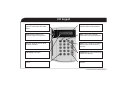
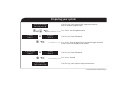
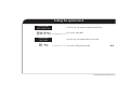
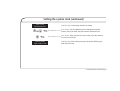
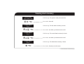
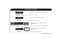
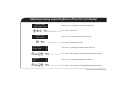
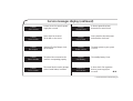
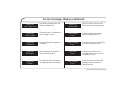
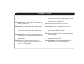
CS-175-275-575 Series
LCD User Guide
98/482/EC Declaration
(Applies to products that have CE mark attached)
This equipment has been approved in accordance with Council Decision 98/482/EC for Pan-European single
terminal connection to the public switched telephone network (PSTN). However, due to differences between
the individual PSTNs provided in different countries, the approval does not, of itself, give an unconditional
assurance of successful operation on every PSTN network termination point.
Aritech is an Interlogix company.
© 2001 Interlogix B.V.
All rights reserved. Interlogix B.V. grants the right to reprint this manual for internal use only.
Interlogix B.V. reserves the right to change information without notice.
Contents
LCD keypad ........................................................... 4
Setting the keypad tone ..................................... 16
Preparing your system .......................................... 6
Setting the system clock ..................................... 17
Turning on your system ......................................... 7
Viewing zone status ........................................... 19
Turning off your system ........................................ 8
Viewing alarm memory ...................................... 20
Turning off your system in case of alarm .............. 9
Reading the event log ........................................ 21
Bypassing (excluding) one or more zones............ 10
Adjusting view/brightness
of the LCD (text display) ..................................... 22
Life safety functions ............................................ 12
Resetting fire detectors ....................................... 13
Changing user codes........................................... 14
Service messages display .................................... 23
Glossary of terms ............................................... 26
Deleting user codes............................................. 15
CS-175-275-575 Series • LCD User Guide
3
LCD keypad
Power (green): When lit, the
system is connected to the mains
power.
Stay: Press to arm perimeter
protection when on the premises.
Ready (green): When lit, the
system is ready to be turned on.
Away: Press to arm complete
system when leaving the premises.
Fire (red): When lit, the fire zone
has been activated.
Bypass: Press to bypass (exclude) a
zone (or zones) in the event of a
zone fault.
LCD display: Messages.
Navigation: Press to scroll through
menu on LCD display.
Chime: Press to turn the chime on
and off.
Star: Used to enable certain
functions.
CS-175-275-575 Series • LCD User Guide
4
LCD keypad
(green). The power light is on if the system is
aPower
connected to the mains and if the battery is okay. The
power light will flash if the system has a low battery condition
or when the battery is not connected. The power light is off if
the mains is cut.
(green). The ready LED is on when the system is
bReady
ready to arm, and flashes when the system is ready to
force arm. If the LED is off, the system cannot be armed,
generally because there is a zone fault.
Fire (red). When the fire LED is lit, a fire zone has been
activated. A rapidly flashing fire LED means that there is a
problem with the fire zone.
c
This function key part arms your system. Pressing it
gStay.
disarms all interior zones but leaves the perimeter
protected.
hAway. Press to arm all zones before leaving.
iBypass. Press to bypass (exclude) zones.
Navigation keys. These allow you to scroll
jkthrough lists and options on the LCD display.
lChime. Press to turn the chime on and off.
@Hash key. Used to access modules and locations.
$Star. Used to access tasks and enter data.
CS-175-275-575 Series • LCD User Guide
5
Preparing your system
System Not Ready
For help, press
LCD Message: Your system is NOT ready to be turned on,
doors or windows might be open.
j or k S
X Fault
Zone X
or
User Action: Use the up/down arrow.
X Bypass
Zone X
i S
X Fault Bypass
Zone X
or
@ S
System Ready
Type code to arm
LCD Message: Zone information.
User Action: Press the bypass key if you want to bypass (exclude)
a zone, so you can arm part of your system.
X Okay
Zone X
LCD Message: Zone information.
User Action: Press #.
LCD Message: Your system is ready to be turned on.
CS-175-275-575 Series • LCD User Guide
6
Turning on your system
OPTION 1: Using the function keys (This feature must be programmed by the installer.)
System Ready
Type code to arm
g S
LCD Message: Your system is ready to be turned on.
h S
System Armed
Zone(s) Bypassed
or
System Armed
All Zones Secure
User Action: For stay mode, push the stay button,
for away mode push the away button.
LCD Message: Your system is either protected
partially or completely.
OPTION 2: Typing your user code
System Ready
Type code to arm
e S
System Armed
All Zones Secure
LCD Message: Your system is ready to be turned on.
User Action: Type your user code for arming.
LCD Message: Your system is turned on.
CS-175-275-575 Series • LCD User Guide
7
Turning off your system
System Armed
All Zones Secure
e S
System Ready
Type code to arm
LCD Message: Your system is turned on.
User Action: Type your user code to turn off your system.
LCD Message: Your system is ready to be turned on.
CS-175-275-575 Series • LCD User Guide
8
Turning off your system in case of alarm
ALARM Zone X
e S
X Alarm Mem.
Zone X
@ S
System Ready
Type code to arm
LCD Message: An alarm has occurred in zone X.
User Action: Type your user code to turn off your system.
LCD Message: The last alarm is shown on the LCD message
for verification.
User Action: Press # to leave this LCD message.
LCD Message: Your system is ready to be turned on.
CS-175-275-575 Series • LCD User Guide
9
Bypassing (excluding) one or more zones
System Not Ready
For help, press
LCD Message: Your system is NOT ready to be turned on.
jk S
User Action: Use the up/down arrow.
1 Okay
Zone 1
LCD Message: Shows the state of the first zone.
jk S
2 Okay
Zone 2
or
User Action: Use the up/down arrow.
2 Bypass
Zone 2
User Action: Press the bypass key to toggle
between ‘Okay’ and ‘Bypass’.
i S
2 Bypass
Zone 2
or
@ S
LCD Message: Zone information.
2 Okay
Zone 2
LCD Message: Zone information.
User Action: Press # to exit this menu.
CS-175-275-575 Series • LCD User Guide
10
Bypassing (excluding) one or more zones (continued)
System Ready
Type code to arm
e S
System Armed
Zone(s) Bypassed
LCD Message: Your system is ready to be turned on.
User Action: Type your user code to turn on the system.
LCD Message: Your system is turned on,
but zones are bypassed (excluded) and not protected.
CS-175-275-575 Series • LCD User Guide
11
Life safety functions
You must press and hold the keys for 2 seconds to activate these functions!
FIRE
&+“S
MEDICAL
‘+§S
PERSONAL
ATTACK
è+çS
User action: Press keys 1 and 3 together for two seconds.
FIRE. A fire alarm is started and a message is sent
to the central station.
User action: Press keys 4 and 6 together for two seconds.
MEDICAL. A medical alert is sent to the central station.
User action: Press keys 7 and 9 together for two seconds.
A personal attack alert is sent to the central station,
and if programmed the sirens can be heard.
CS-175-275-575 Series • LCD User Guide
12
Resetting fire detectors
ALARM
fire alarm
e S
LCD Message: Alarm message after a fire alarm.
User Action: Type your user code to turn the system off.
8 Alarm Mem.
fire alarm
@S
User Action: Press #
System Ready
Type code to arm
LCD Message: Your system is turned off, and the fire detector
has been activated.
$ èS
User Action: Press * 7 in order to reset the fire alarm
The smoke detector has been reset. This may take 10 seconds.
The fire LED (red) will turn off.
System Ready
Type code to arm
LCD Message: Your system is turned off, and the fire detector
has been reset. The fire LED goes off if all detectors have been reset.
CS-175-275-575 Series • LCD User Guide
13
Changing user codes
System Ready
Type code to arm
$ (S
Please Enter
Your Code
eS
Enter 2 digit ID
&!S or @S
Enter new code
18 * * * *
§(‘“ S
LCD Message: The system is ready to be turned on.
User Action: Press * 5.
LCD Message: The system asks for a master user code.
User Action: Enter your master user code.
LCD Message: Enter the two digit ID for the new or existing user.
User Action: Enter the user ID, for example 18,
or # to cancel operation.
LCD Message: Enter the new code for this user.
User Action: Type the new user code, for example, 6543.
CS-175-275-575 Series • LCD User Guide
14
Deleting user codes
System Ready
Type code to arm
$ (S
LCD Message: The system is ready to be turned on.
User Action: Press * 5.
Please Enter
Your Code
LCD Message: The system asks for a master user code.
e S
User Action: Enter your master user code.
Enter 2 digit ID
&!S or @S
ggggS
LCD Message: Enter the two digit ID for the new or existing user.
User Action: Enter the user ID, for example 18,
or # to cancel operation.
User Action: Press G four times to delete the current user.
CS-175-275-575 Series • LCD User Guide
15
Setting the keypad tone
System Ready
Type code to arm
$à S
Raise tone
Lower tone
j or k S
@ S
LCD Message: The system is ready for arming.
User Action: Press * 0.
LCD Message: You will hear the current tone.
User Action: Use up/down arrow to adjust the keypad tone.
User Action: Use # to accept the tone you like.
CS-175-275-575 Series • LCD User Guide
16
Setting the system clock
System Ready
Type code to arm
LCD Message: The system is ready to be turned on.
$çèS
User Action: Press * 97.
Please Enter
Your Code
LCD Message: The system asks for a user code.
e S
User Action: Enter your user code.
CS-175-275-575 Series • LCD User Guide
17
Setting the system clock (continued)
Wed 16:09
29 November 01
j or k S
LCD Message: Current date and time are shown.
User Action: Use the up/down arrow to change the hour,then
minutes, day of the week, day of the month, month and year.
$ S
User Action: After you have the correct value, press * to move to
the next item in the list.
System Ready
Type code to arm
LCD Message: After selecting the year, the system will bring you
back to the first step.
CS-175-275-575 Series • LCD User Guide
18
Viewing zone status
System Ready
Type code to arm
LCD Message: The system is ready to be turned on.
$j S
User Action: Press * and up arrow.
1 Okay
Living room
j or k S
2 Okay
Bed room
j or k S
LCD Message: The first zone is shown.
User Action: Use either up or down arrow to scroll.
LCD Message: The second zone is shown.
User Action: Use either up or down arrow to scroll.
3 Okay
Front entrance
LCD Message: The third zone is shown.
@ S
User Action: Press # to exit this menu
CS-175-275-575 Series • LCD User Guide
19
Viewing alarm memory
System Ready
Type code to arm
$“ S
LCD Message: The system is ready to be turned on.
User Action: Press * 3.
3 Alarm Mem.
Zone 3
LCD Message: The first alarm in memory is shown.
j or k S
User Action: Use either up or down arrow to scroll.
5 Alarm Mem.
Zone 5
LCD Message: The second alarm in memory is shown.
j or k S
User Action: Use either up or down arrow to scroll.
6 Alarm Mem.
Zone 6
LCD Message: The third alarm in memory is shown.
@ S
User Action: Press #, to exit this menu.
CS-175-275-575 Series • LCD User Guide
20
Reading the event log
System Ready
Type code to arm
LCD Message: The system is ready to be turned on.
$ çà S
Event
Date/Time
User Action: Press * 90.
Please Enter
Your Code
LCD Message: The system asks for a user code.
e S
User Action: Enter your user code.
Open 5
9/25 17:32
User or zone
P3*
Partition
jk S
Close 5
9/25 17:32
@ S
P2*
LCD Message: User 5 has opened partition 3 at 17:32
on September 25th.
User Action: Use up/down arrow to scroll through the events.
* The event
has not been
reported to the
central station.
LCD Message: User 5 has closed partition 2 at 17:32
on September 25th.
User Action: Press # to exit this menu.
CS-175-275-575 Series • LCD User Guide
21
Adjusting viewing angle/brightness of the LCD (text display)
System Ready
Type code to arm
$ ç& S
LCD Message: The system is ready to be turned on.
User Action: Press * 91.
Please Enter
Your Code
LCD Message: The system asks for a user code.
e S
User Action: Enter your user code.
Raise view
Lower view
J
K
j or k$ S
Brighten
Dim
J
K
j or k$ S
LCD Message: Change the viewing angle of the LCD.
User Action: Use arrow keys to change followed by * to accept.
LCD Message: Change the brightness of the LCD.
User Action: Use arrow keys to change followed by * to accept.
CS-175-275-575 Series • LCD User Guide
22
Service messages display
Service Required
Type *2 for help
LCD Message: Please contact your installer.
$é S
User Action: Press * 2 to see what is causing the problem.
Expansion
box tamper
LCD Message: This message represents a tamper
of an expansion box or a keypad.
@ S
User Action: Press # to exit the menu.
CS-175-275-575 Series • LCD User Guide
23
Service messages display (continued)
Control
Over-current
A short circuit of a control’s power
supply has occurred.
Control
Ground fault
A short to ground has been
detected on a control circuit.
Control
Siren trouble
Open circuit has occurred
on the bell or siren circuit.
Control
Loss of time
Your system has lost total power
and needs the clock reset.
Control
Box tamper
(Optional) The Box Tamper circuit
has activated.
Control
Power trouble
The mains power to your system
is not on.
Control
Phone trouble
The phone line connected to the
control is not operating properly.
Control
Low Battery
The standby battery is low.
Control
Fail to comm.
The control tried to send a message
to the Central Station, but failed.
Expansion
over-current
A short circuit of an expansion
devices’ power supply has
occurred.
CS-175-275-575 Series • LCD User Guide
24
Service messages display (continued)
Expansion
Aux. comm. fail
An auxiliary reporting device has
failed to communicate.
Expansion
Siren trouble
Open circuit has occurred on the
bell or siren circuit of the expander.
Expansion
Power trouble
The mains power to an expansion
power supply is not on.
Zone Tamper,
Press *
A zone is tampered. Press * to
identify the tampered zone.
Expansion
Low battery
An expansion power supply has a
low battery
Zone Low Batt,
Press *
Expansion
Box tamper
A box containing an expansion
device has been opened.
Expansion
Trouble
An expansion device or keypad is
not reporting to the control panel.
A wireless device has a low battery.
Press * to identify the zone.
Zone Lost,
Press *
A wireless zone device is not
reporting to the control. Press *
to identify the zone.
Zone Trouble,
Press *
A zone has some form of trouble
(probably wiring). Press * to
identify the zone.
CS-175-275-575 Series • LCD User Guide
25
Glossary of terms
Armed The security system is turned on.
Away Mode Turns on all of the security system.
Forced arming An option that allows the system to be armed
with one or more zones open. When the system is ready
to be force armed, the ready LED flashes. Zones that are
not closed do not create an alarm.
Central station Location which monitors the alarm data sent
during an alarm report.
Function Key A key dedicated for a particular task.
Chime feature An option that allows the keypad to sound a
ding-dong whenever an entry/exit door is opened.
Group bypass An option that allows the user to bypass
multiple zones with a single operation.
Event Log A temporary log kept in the memory of the security
system, which contains all the alarms and faults that
occurred between turning your system on and off.
LCD Liquid Crystal Display. This is the text display which gives
you information about your system.
Fire detector Reset The fire detector once activated must be
explicitly reset to become operational again. The system
cannot be armed after a fire alarm until the fire detector
has been reset.
Fire LED A steady fire LED means a fire zone has been
activated. A rapidly flashing fire LED means that a fire
zone is in a trouble condition.
LED Light Emitting Diode. The LEDs on the keypad give system
status information.
Master user code A master arm/disarm code that can also
program parts of the system.
Partitioned system A system divided into multiple areas in
which its own user or users control each area.
Perimeter The outer edge of the protected area.
CS-175-275-575 Series • LCD User Guide
26
Glossary of terms (continued)
Power LED When lit, the system is connected to the mains
power.
Ready LED When lit, the system is ready to be turned on.
Stay Mode Turns on the perimeter protection part of the
security system.
Tamper If the security system is interfered with, a tamper is
recorded. You should contact your installer.
User code A four or six digit code used to arm or disarm the
system.
Zone An area protected by a group of one or more detection
devices.
CS-175-275-575 Series • LCD User Guide
27
ISO 9001 Certified
14 5113 999-1