1
SPLIT-TYPE, HEAT PUMP AIR CONDITIONERS
SPLIT-TYPE, AIR CONDITIONERS
February 2012
No. OCH491
REVISED EDITION-A
SERVICE MANUAL
Indoor unit
[Model names]
PCA-RP50KAQ
PCA-RP60KAQ
PCA-RP71KAQ
PCA-RP100KAQ
PCA-RP125KAQ
PCA-RP140KAQ
[Service Ref.]
PCA-RP50KAQ
PCA-RP60KAQ
PCA-RP71KAQ
PCA-RP100KAQ
PCA-RP125KAQ
PCA-RP140KAQ
Revision:
• SUZ-KA50/60/71VA3.TH-A
have been added as
connectable outdoor units
in REVISED EDITION-A.
• Some descriptions have
been modified.
• Please void OCH491.
NOTE:
• This manual describes only
service data of the indoor
units.
• RoHS compliant products
have <G> mark on the
spec name plate.
CONTENTS
INDOOR UNIT
ON/OFF
PARTS CATALOG (OCB491)
TEMP
TEMP.
WIRELESS REMOTE
CONTROLLER
(Option)
Model name
indication
1. REFERENCE MANUAL................................... 2
2. SAFETY PRECAUTION................................... 3
3. PART NAMES AND FUNCTIONS....................4
4. SPECIFICATIONS............................................ 9
5. NOISE CRITERION CURVES ....................... 12
6. OUTLINES AND DIMENSIONS..................... 14
7. WIRING DIAGRAM............................................. 18
8. REFRIGERANT SYSTEM DIAGRAM............. 19
9. TROUBLESHOOTING................................... 20
10. SPECIAL FUNCTION..................................... 35
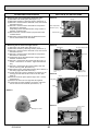
11. DISASSEMBLY PROCEDURE.......................39
ON/OFF
WIRED REMOTE
CONTROLLER
(Option)
1
REFERENCE MANUAL
1-1. OUTDOOR UNIT’S SERVICE MANUAL
Service Ref.
Service Manual No.
SUZ-KA50/60/71VA3.TH-A
OCH511 / OCB511
PUHZ-RP50/60/71VHA4
PUHZ-RP100/125/140VKA
PUHZ-RP100/125/140/200/250YKA
PUHZ-RP200YKAR1
OCH451
OCB451
PU(H)-P71/100VHAR3.UK
PU(H)-P71/100/125/140YHAR3.UK
OC379
PUHZ-P100/125/140VHA3R2.UK
PUHZ-P100/125/140YHAR1.UK
OCH415 / OCB415
PUHZ-P200/250YHA3R2
OCH424 / OCB424
SUZ-KA50/60/71VA2.TH
OCH472
SUZ-KA50/60/71VA2.TH-A
OCH473
1-2. TECHNICAL DATA BOOK
Series (Outdoor unit)
Manual No.
SUZ-KA • VA
OCS03
PUHZ-RP • HA4
PUHZ-RP • KA
OCS16
PUHZ-P • VHA3
PUHZ-P • YHAR3
OCS17
Note:
The phrase "Wired remote controller" in this service manual refers only to the PAR-21MAA.
If you need any information for the PAR-30MAA, please refer to the instruction book included in PAR-30MAA box.
OCH491A
2
2
SAFETY PRECAUTION
2-1. ALWAYS OBSERVE FOR SAFETY
Before obtaining access to terminal, all supply
circuits must be disconnected.
2-2. CAUTIONS RELATED TO NEW REFRIGERANT
Cautions for units utilising refrigerant R410A
Use a vacuum pump with a reverse flow check
valve.
Use new refrigerant pipes.
In case of using the existing pipes for R22, be careful with
the followings.
· For RP100, 125 and 140, be sure to perform replacement operation before test run.
· Change flare nut to the one provided with this product.
Use a newly flared pipe.
· Avoid using thin pipes.
Make sure that the inside and outside of refrigerant piping is clean and it has no contaminants
such as sulfur, oxides, dirt, shaving particles, etc,
which are hazard to refrigerant cycle.
In addition, use pipes with specified thickness.
Contamination inside refrigerant piping can cause deterioration of refrigerant oil etc.
Use the following tools specifically designed for
use with R410A refrigerant.
The following tools are necessary to use R410A refrigerant.
Gauge manifold
Charge hose
Gas leak detector
Torque wrench
Tools for R410A
Flare tool
Size adjustment gauge
Vacuum pump adaptor
Electronic refrigerant
charging scale
Handle tools with care.
If dirt, dust or moisture enters into refrigerant cycle, that can
cause deterioration of refrigerant oil or malfunction of compressor.
Store the piping to be used indoors during
installation, and keep both ends of the piping
sealed until just before brazing. (Leave elbow
joints, etc. in their packaging.)
Do not use a charging cylinder.
If dirt, dust or moisture enters into refrigerant cycle, that can
cause deterioration of refrigerant oil or malfunction of compressor.
The refrigerant oil applied to flare and flange
connections must be ester oil, ether oil or
alkylbenzene oil in a small amount.
If a charging cylinder is used, the composition of refrigerant will change and the efficiency will be lowered.
Use the specified refrigerant only.
If large amount of mineral oil enters, that can cause deterioration of refrigerant oil etc.
Charge refrigerant from liquid phase of gas
cylinder.
If the refrigerant is charged from gas phase, composition
change may occur in refrigerant and the efficiency will be
lowered.
Never use any refrigerant other than that specified.
Doing so may cause a burst, an explosion, or fire when the
unit is being used, serviced, or disposed of.
Correct refrigerant is specified in the manuals and on the
spec labels provided with our products.
We will not be held responsible for mechanical failure,
system malfunction, unit breakdown or accidents caused
by failure to follow the instructions.
Ventilate the room if refrigerant leaks during
operation. If refrigerant comes into contact with
a flame, poisonous gases will be released.
Do not use refrigerant other than R410A.
If other refrigerant (R22 etc.) is used, chlorine in refrigerant can cause deterioration of refrigerant oil etc.
OCH491A
Vacuum pump oil may flow back into refrigerant cycle and
that can cause deterioration of refrigerant oil etc.
3
[1] Cautions for service
(1) Perform service after recovering the refrigerant left in unit completely.
(2) Do not release refrigerant in the air.
(3) After completing service, charge the cycle with specified amount of refrigerant.
(4) When performing service, install a filter drier simultaneously.
Be sure to use a filter drier for new refrigerant.
[2] Additional refrigerant charge
When charging directly from cylinder
· Check that cylinder for R410A on the market is syphon type.
· Charging should be performed with the cylinder of syphon stood vertically. (Refrigerant is charged from liquid phase.)
Unit
Gravimeter
[3] Service tools
Use the below service tools as exclusive tools for R410A refrigerant.
No.
1
Tool name
Gauge manifold
Specifications
· Only for R410A
· Use the existing fitting specifications. (UNF1/2)
· Use high-tension side pressure of 5.3MPa·G or over.
2
Charge hose
· Only for R410A
· Use pressure performance of 5.09MPa·G or over.
3
Electronic scale
4
Gas leak detector
· Use the detector for R134a, R407C or R410A.
5
Adaptor for reverse flow check
· Attach on vacuum pump.
6
Refrigerant charge base
7
Refrigerant cylinder
—
—
· Only for R410A
· Top of cylinder (Pink)
· Cylinder with syphon
8
3
Refrigerant recovery equipment
—
PART NAMES AND FUNCTIONS
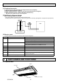
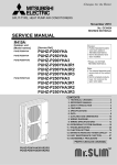
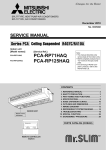
3-1. INDOOR UNIT
Louver
Air outlet
Vane
Air intake
OCH491A
4
Filter
(Inside of Air intake)
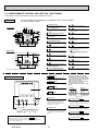
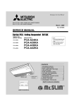
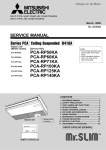
3-2. WIRELESS REMOTE CONTROLLER (OPTION)
* The functions which can be used are restricted according to the model.
CHECK TEST RUN display
Indicate that the unit is being checked or
test-run.
MODEL SELECT display
display
Blinks when model is selected.
Lights up while the signal is transmitted to
the indoor unit when the button is pressed.
Temperature setting display
Indicates the desired temperature setting
which is set.
CLOCK display
OPERATION MODE display
Displays the current time.
OPERATION MODE display
Indicates which operation mode is in effect.
TIMER display
CHECK TEST
MODEL RUN
SELECT
FAN
°F
°C
STOP AMPM
SWING
“” “
START AMPM
NOT AVAILABLE
display
The vertical direction of airflow is indicated.
ON/OFF
Displays when in timer operation or when
setting timer.
“
TEMP
” display
Displays the order of timer operation.
”“
” display
Displays whether timer is on or off.
display
button
Displays selected fan speed.
Sets any desired room temperature.
ON/OFF button
The unit is turned ON and OFF alternately
each time the button is pressed.
FAN SPEED SELECT button
MODE
FAN
AUTO STOP
VANE
AUTO START
CHECK LOUVER
h
Changes the fan speed.
TEST RUN
min
MODE SELECT button
Switches the operation mode between
COOLING/DRY/FAN/HEATING and AUTO
mode.
SET
RESET
TIMER CONTROL buttons
AUTO STOP (OFF timer): when this switch
is set, the air conditioner will be
automatically stopped at the preset time.
AUTO START (ON timer): when this switch is
set, the air conditioner will be automatically
started at the preset time.
CLOCK
"h" and "min" buttons
Buttons used to set the “hour and minute” of
the current time and timer settings.
LOUVER button
CHECK-TEST RUN button
Changes left / right airflow direction.
Performs an inspection check or test
operation. Do not use it for normal operation.
CLOCK button
VANE CONTROL button
RESET button
Changes the air flow direction.
OCH491A
SET button
5
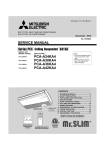
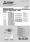
3-3. WIRED REMOTE CONTROLLER (OPTION) <PAR-30MAA>
* The functions which can be used are restricted according to the model.
The main display can be displayed in two different modes: "Full" and "Basic."
The factory setting is "Full."
Display
13 15
12 14 16 17 18
Full mode
Fri
6
7
8
9
10
1
11
20
Room
Set temp.
Cool
3
19
Auto
4
1 Operation mode
12
Indoor unit operation mode appears here.
Appears when the buttons are locked.
2 Preset temperature
13
Preset temperature appears here.
Appears when the On/Off timer or Night setback
function is enabled.
3 Clock
(See the Installation Manual.)
14
Current time appears here.
Appears when the Weekly timer is enabled.
4 Fan speed
15
Fan speed setting appears here.
Appears while the units are operated in the
energy-save mode.
5 Button function guide
Mode
Temp.
Fan
2
21
16
Functions of the corresponding buttons appear
here.
Appears while the outdoor units are operated in
the silent mode.
6
17
Appears when the ON/OFF operation is centrally
controlled.
5
Appears when the built-in thermistor on the
remote controller is activated to monitor the
room temperature (a).
7
Basic mode
Appears when the operation mode is centrally
controlled.
2
Fri
3
appears when the thermistor on the
indoor unit is activated to monitor the room
temperature.
8
18
Appears when the preset temperature is centrally
controlled.
1
Cool
Set temp.
Auto
Indicates the vane setting.
9
4
19
Appears when the filter reset function is centrally
controlled.
Indicates the louver setting.
10
Mode
Temp.
Fan
Indicates the ventilation setting.
11 Room temperature
(See the Installation Manual.)
5
* All icons are displayed for explanation.
20
Indicates when filter needs maintenance.
21
Appears when the preset temperature range is
restricted.
Current room temperature appears here.
Controller interface
1 ON/OFF button
Press to turn ON/OFF the indoor unit.
2 SELECT button
Press to save the setting.
3 RETURN button
5
The functions of the function buttons
change depending on the screen. Refer
to the button function guide that appears
at the bottom of the LCD for the functions
they serve on a given screen.
When the system is centrally controlled,
the button function guide that
corresponds to the locked button will not
appear.
Main display
Press to return to the previous screen.
Main menu
Fri
Room
4 MENU button
Cool
Set temp.
Auto
Mode
Temp.
Fan
Main
Main menu
Vane·Louver·Vent. (Lossnay)
High power
Timer
Weekly timer
OU silent mode
Main display:
Cursor
Page
Press to bring up the Main menu.
7
6
4
3
2
1
Function buttons
7
8
9
10
5 Backlit LCD
9
0
7
8
9
0
Function guide
Operation settings will appear.
When the backlight is off, pressing any
button turns the backlight on and it
will stay lit for a certain period of time
depending on the screen.
7 Function button F1
6 ON/OFF lamp
Main display: Press to decrease temperature.
Main menu: Press to move the cursor up.
This lamp lights up in green while the unit
is in operation. It blinks while the remote
controller is starting up or when there is
an error.
• When the backlight is off, pressing any button turns the backlight on and
Main display: Press to change the operation
mode.
Main menu: Press to move the cursor down.
8 Function button F2
9 Function button F3
Main display: Press to increase temperature.
Main menu: Press to go to the previous page.
10 Function button F4
does not perform its function. (except for the ON/OFF button)
Main display: Press to change the fan speed.
Main menu: Press to go to the next page.
• Most settings (except ON/OFF, mode, fan speed, temperature) can be
made from the Menu screen.
OCH491A
8
6
Main menu list
Setting and display items
Setting details
Vane · Louver · Vent.
(Lossnay)
Use to set the vane angle.
• Select a desired vane setting from five different settings.
Use to turn ON / OFF the louver.
• Select a desired setting from "ON" and "OFF."
Use to set the amount of ventilation.
• Select a desired setting from "Off," "Low," and "High."
High power
Use to reach the comfortable room temperature quickly.
• Units can be operated in the High-power mode for up to 30 minutes.
Timer
On/Off timer
Use to set the operation On/Off times.
• Time can be set in 5-minute increments.
* Clock setting is required.
Auto-Off timer
Use to set the Auto-Off time.
• Time can be set to a value from 30 to 240 in 10-minute increments.
Filter information
Use to check the filter status.
• The filter sign can be reset.
Error information
Use to check error information when an error occurs.
• Error code, error source, refrigerant address, unit model, manufacturing number, contact information (dealer's phone
number) can be displayed.
* The unit model, manufacturing number, and contact information need to be registered in advance to be displayed.
Weekly timer
Use to set the weekly operation On / Off times.
• Up to eight operation patterns can be set for each day.
* Clock setting is required.
* Not valid when the On/Off timer is enabled.
Energy saving Auto return
Use to get the units to operate at the preset temperature after performing energy-save operation for a specified
time period.
• Time can be set to a value from 30 and 120 in 10-minute increments.
* This function will not be valid when the preset temperature ranges are restricted.
Schedule
Night setback
Restriction
Maintenance
Use to make Night setback settings.
• Select "Yes" to enable the setting, and "No" to disable the setting. The temperature range and the start/stop times can be set.
* Clock setting is required.
Temp. range
Use to restrict the preset temperature range.
• Different temperature ranges can be set for different operation modes.
Operation lock
Use to lock selected functions.
• The locked functions cannot be operated.
Auto descending panel Auto descending panel (Optional parts) Up / Down you can do.
Manual vane angle
Initial setting
Initial setting
Service
Set the start/stop times to operate the units in the energy-save mode for each day of the week, and set the
energy-saving rate.
• Up to four energy-save operation patterns can be set for each day.
• Time can be set in 5-minute increments.
• Energy-saving rate can be set to a value from 0% and 50 to 90% in 10% increments.
* Clock setting is required.
Use to set the vane angle for each vane to a fixed position.
Main/Sub
When connecting two remote controllers, one of them needs to be designated as a sub controller.
Clock
Use to set the current time.
Main display
Use to switch between "Full" and "Basic" modes for the Main display.
• The default setting is "Full."
Contrast
Use to adjust screen contrast.
Display details
Make the settings for the remote controller related items as necessary.
Clock: The factory settings are "Yes" and "24h" format.
Temperature: Set either Celsius (°C) or Fahrenheit (°F).
Room temp. : Set Show or Hide.
Auto mode: Set the Auto mode display or Only Auto display.
Auto mode
Whether or not to use the AUTO mode can be selected by using the button.
This setting is valid only when indoor units with the AUTO mode function are connected.
Administrator password
The administrator password is required to make the settings for the following items.
• Timer setting • Energy-save setting • Weekly timer setting
• Restriction setting • Outdoor unit silent mode setting • Night set back
Language selection
Use to select the desired language.
Test run
Select "Test run" from the Service menu to bring up the Test run menu.
• Test run • Drain pump test run
Select "Input maintenance Info." from the Service menu to bring up the Maintenance information screen.
The following settings can be made from the Maintenance Information screen.
• Model name input • Serial No. input • Dealer information input
Make the settings for the indoor unit functions via the remote controller as necessary.
This setting is required only when the operation of City Multi units is interlocked with LOSSNAY units.
Input maintenance
Function setting
LOSSNAY setting
(City Multi only)
Check
Error history: Display the error history and execute delete error history.
Refrigerant leak check: Refrigerant leaks can be judged.
Smooth maintenance: The indoor and outdoor maintenance data can be displayed.
Request cord: Details of the operation data including each thermistor temperature and error history can be checked.
Self check
Error history of each unit can be checked via the remote controller.
Maintenance password Take the following steps to change the maintenance password.
Remote controller
When the remote controller does not work properly, use the remote controller checking function to troubleshoot the problem.
check
OCH491A
7
3-4. WIRED REMOTE CONTROLLER (OPTION) <PAR-21MAA>
* The functions which can be used are restricted according to the model.
Display Section
For purposes of this explanation,
all parts of the display are shown.
During actual operation, only
the relevant items will be lit.
“Sensor” indication
Day-of-Week
Displays when the remote controller
sensor is used.
Shows the current day of the week.
Time/Timer Display
“Locked” indicator
Shows the current time, unless the simple or Auto Off
timer is set.
If the simple or Auto Off timer is set, the time to be
switched off is shown.
Indicates that remote controller buttons have been locked.
Identifies the current operation
“Clean The Filter” indicator
Shows the operating mode, etc.
*Multilanguage display is available.
To be displayed on when it is time to
clean the filter.
TIME SUN MON TUE WED THU FRI SAT
TIMER
Hr
ON
AFTER
Indicates that operation from the
remote controller has been prohibited by a master controller.
FUNCTION
FILTER
°F°C
°F°C
“Centrally Controlled” indicator
Timer indicators
AFTER OFF
ERROR CODE
The indicator comes on if the corresponding timer is set.
WEEKLY
SIMPLE
AUTO OFF
ONLY1Hr.
Fan Speed indicator
Shows the selected fan speed.
“Timer is Off” indicator
Indicates that the timer is off.
Up/Down Air Direction indicator
The indicator shows the direction of the outcoming airflow.
“One Hour Only” indicator
Temperature Setting
Shows the target temperature.
Displays if the airflow is set to
low or downward during COOL
or DRY mode. (Operation varies
according to model.)
The indicator goes off in 1 hour,
when the airflow direction
also changes.
Room Temperature display
Shows the room temperature. The room
temperature display range is 46–102˚F.
The display blinks if the temperature
is less than 46˚F or 102˚F or more.
Ventilation indicator
Appears when the unit is running in
Ventilation mode.
Louver display
Indicates the action of the swing louver.
Does not appear if the louver is not
running.
(Power On indicator)
Indicates that the power is on.
Operation Section
ON/OFF button
Temperature setting buttons
Down
Fan Speed button
Up
Timer Menu button
(Monitor/Set button)
Filter
button
(<Enter> button)
Mode button (Return button)
TEMP.
ON/OFF
Set Time buttons
Check button (Clear button)
Back
Ahead
Timer On/Off button
(Set Day button)
Test Run button
MENU
BACK
PAR-21MAA
MONITOR/SET
ON/OFF
FILTER
DAY
CHECK TEST
OPERATION
CLOCK
Airflow Up/Down button
CLEAR
Louver button
(
Operation button)
To return operation
number
Opening the
cover
Ventilation button
( Operation button)
Built-in temperature sensor
OCH491A
8
To go to next operation
number
4
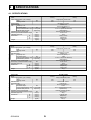
SPECIFICATIONS
INDOOR UNIT
INDOOR UNIT
INDOOR UNIT
4-1. SPECIFICATIONS
Service Ref.
Mode
Power supply(phase, cycle, voltage)
kW
Input
A
Running current
External finish
Heat exchanger
Fan
Fan(drive) × No.
kW
Fan motor output
Airflow(Low-Medium2-Medium1-High) */min(CFM)
Pa(mmAq)
External static pressure
Operation control & Thermostat
dB
Noise level(Low-Medium2-Medium1-High)
mm(in.)
Field drain pipe O.D.
mm(in.)
Dimensions
W
mm(in.)
D
mm(in.)
H
kg(lbs)
Weight
PCA-RP50KAQ
Cooling
0.05
0.37
0.05
0.37
Munsell 6.4Y 8.9/0.4
Plate fin coil
Sirocco fan (direct) x 2
0.090
10-11-13-15(355-390-460-530)
0(direct blow)
Remote controller & built-in
32-34-37-40
26(1)
960(37-13/16)
680(26-3/4)
230(9-1/16)
25(55)
Service Ref.
Mode
Power supply(phase, cycle, voltage)
kW
Input
A
Running current
External finish
Heat exchanger
Fan
Fan(drive) × No.
kW
Fan motor output
Airflow(Low-Medium2-Medium1-High) */min(CFM)
Pa(mmAq)
External static pressure
Operation control & Thermostat
dB
Noise level(Low-Medium2-Medium1-High)
mm(in.)
Field drain pipe O.D.
mm(in.)
Dimensions
W
mm(in.)
D
mm(in.)
H
kg(lbs)
Weight
PCA-RP60KAQ
Cooling
Heating
Single phase, 50Hz, 230V
0.06
0.39
0.06
0.39
Munsell 6.4Y 8.9/0.4
Plate fin coil
Sirocco fan (direct) x 3
0.095
15-16-17-19(530-565-600-670)
0(direct blow)
Remote controller & built-in
33-35-37-40
26(1)
1,280(50-3/8)
680(26-3/4)
230(9-1/16)
32(71)
Service Ref.
Mode
Power supply(phase, cycle, voltage)
kW
Input
A
Running current
External finish
Heat exchanger
Fan
Fan(drive) × No.
kW
Fan motor output
Airflow(Low-Medium2-Medium1-High) */min(CFM)
Pa(mmAq)
External static pressure
Operation control & Thermostat
dB
Noise level(Low-Medium2-Medium1-High)
mm(in.)
Field drain pipe O.D.
mm(in.)
Dimensions
W
mm(in.)
D
mm(in.)
H
kg(lbs)
Weight
OCH491A
Heating
Single phase, 50Hz, 230V
PCA-RP71KAQ
Cooling
Heating
Single phase, 50Hz, 230V
0.06
0.42
0.06
0.42
Munsell 6.4Y 8.9/0.4
Plate fin coil
Sirocco fan (direct) x 3
0.095
16-17-18-20(565-600-635-705)
0(direct blow)
Remote controller & built-in
35-37-39-41
26(1)
1,280(50-3/8)
680(26-3/4)
230(9-1/16)
32(71)
9
INDOOR UNIT
INDOOR UNIT
INDOOR UNIT
Service Ref.
Mode
Power supply(phase, cycle, voltage)
kW
Input
A
Running current
External finish
Heat exchanger
Fan
Fan(drive) × No.
kW
Fan motor output
Airflow(Low-Medium2-Medium1-High) */min(CFM)
Pa(mmAq)
External static pressure
Operation control & Thermostat
dB
Noise level(Low-Medium2-Medium1-High)
mm(in.)
Field drain pipe O.D.
mm(in.)
Dimensions
W
mm(in.)
D
mm(in.)
H
kg(lbs)
Weight
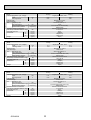
PCA-RP100KAQ
Cooling
0.09
0.65
OCH491A
0.09
0.65
Munsell 6.4Y 8.9/0.4
Plate fin coil
Sirocco fan (direct) × 4
0.160
22-24-26-28(775-850-920-990)
0(direct blow)
Remote controller & built-in
37-39-41-43
26(1)
1,600(63)
680(26-3/4)
230(9-1/16)
36(79)
Service Ref.
Mode
Power supply(phase, cycle, voltage)
kW
Input
A
Running current
External finish
Heat exchanger
Fan
Fan(drive) × No.
kW
Fan motor output
Airflow(Low-Medium2-Medium1-High) */min(CFM)
Pa(mmAq)
External static pressure
Operation control & Thermostat
dB
Noise level(Low-Medium2-Medium1-High)
mm(in.)
Field drain pipe O.D.
mm(in.)
Dimensions
W
mm(in.)
D
mm(in.)
H
kg(lbs)
Weight
Heating
Single phase, 50Hz, 230V
PCA-RP125KAQ
Cooling
Heating
Single phase, 50Hz, 230V
0.11
0.76
0.11
0.76
Munsell 6.4Y 8.9/0.4
Plate fin coil
Sirocco fan (direct) × 4
0.160
23-25-27-29(810-885-955-1025)
0(direct blow)
Remote controller & built-in
39-41-43-45
26(1)
1,600(63)
680(26-3/4)
230(9-1/16)
38(84)
PCA-RP140KAQ
Cooling
Heating
Single phase, 50Hz, 230V
0.14
0.90
0.14
0.90
Munsell 6.4Y 8.9/0.4
Plate fin coil
Sirocco fan (direct) × 4
0.160
24-26-29-32(850-920-1025-1130)
0(direct blow)
Remote controller & built-in
41-43-45-48
26(1)
1,600(63)
680(26-3/4)
230(9-1/16)
39(86)
10
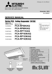
4-2. FRESH AIR INTAKE AMOUNT & STATIC PRESSURE CHARACTERISTICS
■ PCA-RP60, 71KAQ
PCA-RP50KAQ
■
50
50
0
Static pressure[Pa]
Static pressure[Pa]
0
-50
-100
-150
-200
-250
-300
-50
-100
-150
-200
-250
-300
0
1
2
3
4
0
1
Airflow rate[m³/min]
A
0
50
Q
-50
-100
2
C
A
-150
E
-200
-250
Q
3
4
3
D
2
Airflow rate[m³/min]
A
Static pressure[Pa]
0
1
Q
Qa
OCH491A
4
Duct characteristics
at site
11
C
Curve in the
graphs
B
1
0
3
How to read curves
■ PCA-RP100, 125, 140KAQ
-300
2
Airflow rate[m³/min]
Q…Designed amount of fresh air intake
<m3/min>
A…Static pressure loss of fresh air
intake duct system with airflow
amount Q
<Pa>
…
B Forced static pressure at air conditioner
inlet with airflow amount Q
<Pa>
C…Static pressure of booster fan with
airflow amount Q
<Pa>
D…Static pressure loss increase amount
of fresh air intake duct system for
airflow amount Q
<Pa>
E…Static pressure of indoor unit with
airflow amount Q
<Pa>
Qa … Estimated amount of fresh air
intake without D
<m3/min>
5
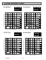
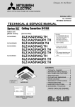
NOISE CRITERION CURVES
NOTCH SPL(dB)
40
High
37
Medium1
34
Medium2
32
Low
PCA-RP60KAQ
LINE
90
90
80
80
70
NC-70
60
NC-60
50
NC-50
40
NC-40
30
NC-30
20
10
OCTAVE BAND SOUND PRESSURE LEVEL, dB (0 dB = 0.0002 μbar)
OCTAVE BAND SOUND PRESSURE LEVEL, dB (0 dB = 0.0002 μbar)
PCA-RP50GA
PCA-RP50KAQ
PCA-RP50GA#1
PCH-P50GAH
NC-70
60
NC-60
50
NC-50
40
NC-40
30
NC-30
APPROXIMATE
THRESHOLD OF
HEARING FOR
CONTINUOUS
NOISE
NC-20
NC-20
10
63
125
250
500
1000
2000
4000
8000
63
125
BAND CENTER FREQUENCIES, Hz
NOTCH SPL(dB)
High
41
Medium1
39
Medium2
37
Low
35
LINE
90
80
80
70
NC-70
60
NC-60
50
NC-50
40
NC-40
30
NC-30
APPROXIMATE
THRESHOLD OF
HEARING FOR
CONTINUOUS
NOISE
63
125
1000
2000
4000
4000
8000
NOTCH SPL(dB)
High
43
Medium1
41
Medium2
39
Low
37
NC-70
50
NC-50
40
NC-40
30
NC-30
APPROXIMATE
THRESHOLD OF
HEARING FOR
CONTINUOUS
NOISE
63
125
NC-20
250
500
1000
2000
BAND CENTER FREQUENCIES, Hz
12
LINE
NC-60
10
8000
BAND CENTER FREQUENCIES, Hz
OCH491A
2000
60
20
500
1000
70
NC-20
250
500
PCA-RP125GA
PCA-RP100KAQ
PCA-RP125GA#1
PCH-P125GAH
90
10
250
BAND CENTER FREQUENCIES, Hz
OCTAVE BAND SOUND PRESSURE LEVEL, dB (0 dB = 0.0002 μbar)
OCTAVE BAND SOUND PRESSURE LEVEL, dB (0 dB = 0.0002 μbar)
PCA-RP100GA
PCA-RP71KAQ
PCA-RP100GA#1
PCH-P100GAH
20
LINE
70
20
APPROXIMATE
THRESHOLD OF
HEARING FOR
CONTINUOUS
NOISE
NOTCH SPL(dB)
High
40
Medium1
37
Medium2
35
Low
33
4000
8000
NOTCH SPL(dB)
High
45
Medium1
43
Medium2
41
Low
39
LINE
PCA-RP140KAQ
PCA-RP140GA
PCA-RP140GA#1
PCH-P140GAH
90
90
80
80
70
NC-70
60
NC-60
50
NC-50
40
NC-40
30
NC-30
20
10
OCTAVE BAND SOUND PRESSURE LEVEL, dB (0 dB = 0.0002 μbar)
OCTAVE BAND SOUND PRESSURE LEVEL, dB (0 dB = 0.0002 μbar)
PCA-RP125KAQ
PCA-RP140GA
PCA-RP140GA#1
PCH-P140GAH
70
50
NC-50
40
NC-40
30
NC-30
NC-20
125
250
500
1000
2000
4000
8000
NC-70
NC-60
10
63
APPROXIMATE
THRESHOLD OF
HEARING FOR
CONTINUOUS
NOISE
63
1m
ceiling
unit
about 1.4m
MICROPHONE
OCH491A
125
NC-20
250
500
1000
2000
BAND CENTER FREQUENCIES, Hz
BAND CENTER FREQUENCIES, Hz
1m
13
LINE
60
20
APPROXIMATE
THRESHOLD OF
HEARING FOR
CONTINUOUS
NOISE
NOTCH SPL(dB)
High
48
Medium1
45
Medium2
43
Low
41
4000
8000
1
2
3
4
5
6
7
8
9
121
Ceiling
461
25
ø1
9
38
38
7
387
18
120°
85
14
2
48
233
246
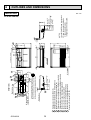
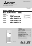
When drain socket
is installed
(Drainage)
2
2
Drainage pipe connection(26mmI.D.)
Drainage pipe connection(for the left arrangement)
Knockout hole for left drain-piping arrangement
Refrigerant-pipe connection(gas pipe side/flared connection)
Refrigerant-pipe connection(liquid pipe side/flared connection)
Knockout hole for upper drain pipe arrangement
Knockout hole for fresh air intake ø100
Knockout hole for wiring arrangement 2-ø22
Knockout hole for wiring arrangement 2-ø26
Air intake
Accessory···Drain socket (I.D. 26)
Electrical box
8
138
86
126
260
4
Air outlet
878
853
960
917(Suspension bolt pitch)
182
140
62
80
1
1
190
24
5
In case of the rear pipe arrangement, make sure to
remove the shaded portions from the independent piece.
Then put the independent piece back in initial position.
(The heat exchanger might be clogged because of dust)
75
3
When electrical box
is pulled down
46
190
2
169
37
76
124
(71)
8
2
85
6
680
230
Electrical box
84 88
254
320
195
57
OCH491A
680
150
18
[FRONT VIEW]
5
10
51
184
(liquid ø6.35)
(gas ø12.7)
When drain socket
is installed
(Drainage)
236
NOTES.
1.Use M10 or W3/8 screw for anchor bolt.
2.Please be sure when installing the
drain pump (option parts),
refrigerant pipe will be only upward.
246
233
203
PCA-RP50KAQ
476
6
OUTLINES AND DIMENSIONS
INDOOR UNIT
Unit : mm
121
169
37
190
46
1
2
3
4
5
6
7
8
9
461
25
ø1
9
38
7
387
18
120°
2
8
48
246
233
(Drainage)
When drain socket
is installed
138
85 86
260
2
Drainage pipe connection(26mmI.D.)
Drainage pipe connection(for the left arrangement)
Knockout hole for left drain-piping arrangement
Refrigerant-pipe connection(gas pipe side/flared connection)
Refrigerant-pipe connection(liquid pipe side/flared connection)
Knockout hole for upper drain pipe arrangement
Knockout hole for fresh air intake ø100
Knockout hole for wiring arrangement 2-ø22
Knockout hole for wiring arrangement 2-ø26
Air intake
Accessory···Drain socket (I.D. 26)
Flare nut ø6.35 (RP60 only)
Electrical box
Ceiling
38
24
4
2
Air outlet
1198
1173
1280
1237(Suspension bolt pitch)
182
140
62
80
1
In case of the rear pipe arrangement, make sure to
remove the shaded portions from the independent piece.
Then put the independent piece back in initial position.
(The heat exchanger might be clogged because of dust)
When electrical box
is pulled down
75
124 76
(71)
3
5
126
1
190
2
8
2
85
680
230
Electrical box
84 88
254
320
195
57
15
680
OCH491A
476
150
[FRONT VIEW]
6
5
10
60
179
203
A
B
246
233
71
180
200
(gas ø15.88)
When drain socket
is installed
(Drainage)
(liquid )
236
4 GAS SIDE
ø15.88
:Initial flare nut size
ø9.52
5 LIQUID SIDE ø6.35
RP60
ø9.52
ø15.88
RP71
Use the current nuts meeting the pipe size of the outdoor unit.
Available pipe size
NOTES.
1.Use M10 or W3/8 screw for anchor bolt.
2.Please be sure when installing the
drain pump (option parts),
refrigerant pipe will be only upward.
51
A
B
PCA-RP60, 71KAQ
Unit : mm
18
1
2
3
4
5
6
7
8
9
16
190
46
Electrical box
461
25
ø1
Ceiling
9
38
24
38
7
387
18
120°
Electrical box
2
8
48
233
246
When drain socket
is installed
(Drainage)
138
260
85 86
1
In case of the rear pipe arrangement, make sure to
remove the shaded portions from the independent piece.
Then put the independent piece back in initial position.
(The heat exchanger might be clogged because of dust)
When electrical box
is pulled down
76
124
2
4
2
Drainage pipe connection(26mmI.D.)
Drainage pipe connection(for the left arrangement)
Knockout hole for left drain-piping arrangement
Refrigerant-pipe connection(gas pipe side/flared connection)
Refrigerant-pipe connection(liquid pipe side/flared connection)
Knockout hole for upper drain pipe arrangement
Knockout hole for fresh air intake ø100
Knockout hole for wiring arrangement 2-ø22
Knockout hole for wiring arrangement 2-ø26
Air intake
Accessory···Drain socket (I.D. 26)
75
3
169
37
121
1
126
190
2
5
Air outlet
1518
1600
1493
1557 (Suspension bolt pitch)
182
140
62
2
85
254
71
80
320
57
8
6
680
84 88
195
230
680
OCH491A
476
[FRONT VIEW]
10
5
246
233
180
200
(liquid ø9.52)
(gas ø15.88)
When drain socket
is installed
(Drainage)
236
NOTES.
1.Use M10 or W3/8 screw for anchor bolt.
2.Please be sure when installing the
drain pump (option parts),
refrigerant pipe will be only upward.
51
PCA-RP100, 125, 140KAQ
Unit : mm
150
18
WIRED REMOTE CONTROLLER
Unit : mm
(Option)
19.5
130
83.5
120
PAR-21MAA
46
19
120
120
PAR-30MAA
83.5
46
OCH491A
17
7
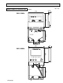
WIRING DIAGRAM
PCA-RP50KAQ
PCA-RP100KAQ
PCA-RP60KAQ
PCA-RP125KAQ
PCA-RP71KAQ
PCA-RP140KAQ
[LEGEND]
SYMBOL
I.B
CN2L
CN32
CN41
CN51
FUSE
LED1
LED2
LED3
SW1
SW2
SWE
X1
R.B
DCL
MF
MV
TB2
NAME
INDOOR CONTROLLER BOARD
CONNECTOR (LOSSNAY)
CONNECTOR (REMOTE SWITCH)
CONNECTOR (HA TERMINAL-A)
CONNECTOR (CENTRALLY CONTROL)
FUSE (T6.3AL250V)
POWER SUPPLY (I.B)
POWER SUPPLY (R.B)
TRANSMISSION (INDOOR-OUTDOOR)
SWITCH (MODEL SELECTION) See table 1
SWITCH (CAPACITY CODE) See table 2
CONNECTOR (EMERGENCY OPERATION)
RELAY (DRAIN PUMP)
WIRED REMOTE CONTROLLER BOARD
REACTOR
FAN MOTOR
VANE MOTOR
TERMINAL BLOCK (Indoor unit Power (option parts))
SYMBOL
TB4
TB5,TB6
NAME
TERMINAL BLOCK (INDOOR/OUTDOOR CONNECTING LINE)
TERMINAL BLOCK (REMOTE CONTROLLER
TRANSMISSION LINE)
ROOM TEMP. THERMISTOR
(0ºC / 15kΩ, 25ºC / 5. 4kΩ DETECT)
PIPE TEMP. THERMISTOR/LIQUID
(0ºC / 15kΩ, 25ºC / 5. 4kΩ DETECT)
COND. / EVA. TEMP. THERMISTOR
(0ºC / 15kΩ, 25ºC / 5. 4kΩ DETECT)
TH1
TH2
TH5
OPTION PARTS
W.B
BZ
LED1
LED2
RU
SW1
SW2
DP
FS
The black square(■)indicates a switch
position.
<Table 1>
<Table 2>SW2 (CAPACITY CODE)
SW1 (MODEL SELECTION)
SW2
SW1
MODELS
Service
MODELS
Service
1 2 3 4 5
PCA-RP50KAQ
ON
OFF
PCA-RP60KAQ
PCB FOR WIRELESS REMOTE CONTROLLER
BUZZER
LED (OPERATION INDICATION : GREEN)
LED (PREPARATION FOR HEATING : ORANGE)
RECEIVING UNIT
EMERGENCY OPERATION (HEAT / DOWN)
EMERGENCY OPERATION (COOL / UP)
DRAIN PUMP
DRAIN FLOAT SWITCH
PCA-RP71KAQ
1 2 3 4 5
1 2 3 4 5
ON PCA-RP100KAQ
OFF
ON PCA-RP125KAQ
OFF
ON PCA-RP140KAQ
OFF
(OPTION PARTS)
TB5
2
1
2
DCL
TRANSMISSION
WIRES
DC12V
1 2
TB6
R.B
YLW
Refer to tables 1 and 2
I.B
VANE CNV(WHT)
SW1
20 18 16 14 12 10 8 6 4 2
J41 J42
SW2
19 17 15 13 11 9 7 5 3 1
Pair No.
CN32
(WHT) 1
CN51(WHT)
5
CN2L
LED3
LED2
2 1
LED1
OUTDOOR 1 3 5
CN01
3
INDOOR/OUTDOOR
COMMUNICATION
CN3C
1
CN41(WHT)
4
FUSE
(BLU)
1 2
–
REMOCON
CN22
1
SWE
(BLK)
1 3
+
(BLU)
ON OFF
1
WIRELESS
CN90
(WHT)
9
FLOAT SW
CN4F
(WHT)
1
LIQUID/PIPE INTAKE
CN44
CN20
(WHT)
(RED)
4
1
4
1 2
7
FAN
CNMF
(WHT)
YLW
ORN
X1
4
D.U.M
1 CNP 3
1
CNB
BZ
5
SW1
LED2
SW2
LED1
RU
MV
M
MS
9
When attaching
drain pump
(option parts),
remove the jumper
connector CN4F
and fit the drain
float switch (FS).
t˚ t˚
TH2 TH5
When attaching
drain pump
(option parts)
FLOAT SW
CN4F
(WHT)
1
t˚
TH1
4
TB4
YLW S1
ORN S2
S3
ORN
BRN
(BLU)
M
1 2 3 4 5
3~
1~
MF
DP
(OPTION PARTS)
Be sure to turn off the source power
and then disconnect fan motor connector.
(Failure to do so will cause trouble in Fan motor)
FS
W.B
(OPTION PARTS)
Notes: 1. SymboIs used in wiring diagram above are,
: Connector,
:Terminal (block).
2. Indoor and outdoor connecting wires are made with poIarities,
make wiring matching terminal numbers (S1, S2, S3).
3. Since the outdoor side electric wiring may change, be sure to
check the outdoor unit electric wiring for servicing.
4. This diagram shows the wiring of indoor and outdoor connecting
wires.(specification of 230V), adopting superimposed system
of power and signal.
1: When work to Supply power separately to indoor and
outdoor units was applied, refer to Fig 1.
. 2: For power supply system of this unit, refer to the caution
label located near this diagram.
OCH491A
1 (Fig. 1)
CN01
I.B
(BLK)
YLW
5
3
1
DCL
YLW
ORN
RED
BLU
GRN/YLW
TB2
L
N
YLW TB4
ORN S1
ORN S2
BRN
S3
I.B
1 3 INDOOR/OUTDOOR
CN3C COMMUNICATION
(BLU)
18
POWER SUPPLY
(1PHASE)
230V 50Hz
TO OUTDOOR UNIT
TO OUTDOOR
UNIT
Service
1 2 3 4 5
1 2 3 4 5
1 2 3 4 5
ON
OFF
ON
OFF
ON
OFF
8
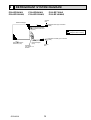
REFRIGERANT SYSTEM DIAGRAM
PCA-RP50KAQ
PCA-RP100KAQ
PCA-RP60KAQ
PCA-RP125KAQ
PCA-RP71KAQ
PCA-RP140KAQ
Strainer
#50
Heat exchanger
Refrigerant GAS pipe connection
(Flare)
Condenser/evaporator
temperature thermistor
(TH5)
Refrigerant flow in cooling
Refrigerant flow in heating
Refrigerant LIQUID pipe connection
(Flare)
Room temperature
thermistor (TH1)
Pipe temperature
thermistor/liquid
(TH2)
Distributor
with strainer 1/2
#50/#50
OCH491A
Strainer
#50
19
9
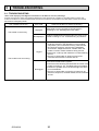
TROUBLESHOOTING
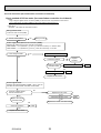
9-1. TROUBLESHOOTING
<Error code display by self-diagnosis and actions to be taken for service (summary)>
Present and past error codes are logged and displayed on the wired remote controller or controller board of outdoor unit.
Actions to be taken for service and the trouble reoccurrence at field are summarized in the table below. Check the contents
below before investigating details.
Unit conditions at service
Error code
Actions to be taken for service (summary)
Displayed
Judge what is wrong and take a corrective action
according to “9-3. Self-diagnosis action table”.
The trouble is reoccurring.
Not displayed
Logged
The trouble is not reoccurring.
Not logged
OCH491A
Conduct troubleshooting and ascertain the cause of the
trouble according to “9-4. Troubleshooting of problems”.
Consider the temporary defects such as the work of
protection devices in the refrigerant circuit including
compressor, poor connection of wiring, noise and etc.
Re-check the symptom, and check the installation
environment, refrigerant amount, weather when the
trouble occurred, matters related to wiring and etc.
Reset error code logs and restart the unit after finishing
service.
There is no abnormality in electrical component,
controller board,remote controller and etc.
Re-check the abnormal symptom.
Conduct trouble shooting and ascertain the cause of the
trouble according to “9-4. Troubleshooting of problems”.
Continue to operate unit for the time being if the cause
is not ascertained.
There is no abnormality concerning of parts such as
electrical component, controller board, remote controller
and etc.
20
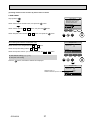
9-2. MALFUNCTION-DIAGNOSIS METHOD BY REMOTE CONTROLLER
<In case of trouble during operation>
When a malfunction occurs to air conditioner, both indoor unit and outdoor unit will stop and operation lamp blinks to inform
unusual stop.
<Malfunction-diagnosis method at maintenance service>
■ Wireless remote controller (Option)
[Procedure]
Refrigerant
address
display
CHECK
CHECK
display
Temperature
button
TEMP
ON/OFF
1. Press the CHECK button twice.
• "CHECK" lights, and refrigerant address
"00" flashes.
• Check that the remote controller's
display has stopped before continuing.
2. Press the temperature
buttons.
• Select the refrigerant address of the
indoor unit for the self-diagnosis.
Note: Set refrigerant address using the
outdoor unit’s DIP switch (SW1).
(For more information, see the
outdoor unit installation manual.)
3. Point the remote controller at
the sensor on the indoor unit
and press the HOUR button.
• If an air conditioner error occurs, the
indoor unit's sensor emits an intermittent
buzzer sound, the operation light
flashes, and the error code is output.
(It takes 3 seconds at most for error
code to appear.)
ON/OFF
button
MODE
FAN
AUTO STOP
VANE
AUTO START
CHECK LOUVER
CHECK
button
min
TEST RUN
SET
h
HOUR
button
RESET
CLOCK
• The check mode is cancelled.
4. Point the remote controller at
the sensor on the indoor unit
and press the ON/OFF button.
OCH491A
21
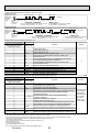
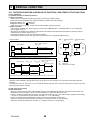
• Refer to the following tables for details on the check codes.
[Output pattern A]
Beeper sounds
OPERATION
INDICATOR
lamp flash
pattern
Beep
Beep Beep Beep
Off
Beep
1st
2 nd
3 rd
nth
On
On
On
On
Beep Beep
1st
Off
On
2 nd · · · Repeated
On
0.5 sec. Approx. 2.5 sec. 0.5 sec. 0.5 sec.
Self-check Approx. 2.5 sec. 0.5 sec. 0.5 sec. 0.5 sec.
starts
(Start signal
Number of flashes/beeps in pattern indicates the check Number of flashes/beeps in pattern indicates
received)
code in the following table (i.e., n=5 for “P5”)
the check code in the following table
[Output pattern B]
Beeper sounds
OPERATION
INDICATOR
lamp flash
pattern
Beep
Beep Beep Beep
1st
Off
Self-check Approx. 2.5 sec.
starts
(Start signal
received)
On
Approx. 3 sec.
2nd
3 rd
On
On
On
0.5 sec. 0.5 sec. 0.5 sec.
Beep
Beep
nth
1st
On
Off
0.5 sec. Approx. 2.5 sec.
Number of flashes/beeps in pattern indicates the check
code in the following table (i.e., n=5 for “U2”)
On
Approx. 3 sec.
Beep
2 nd · · · Repeated
On
On
0.5 sec. 0.5 sec.
Number of flashes/beeps in pattern indicates
the check code in the following table
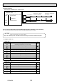
[Output pattern A] Errors detected by indoor unit
Wireless remote controller Wired remote controller
Beeper sounds/OPERATION
Symptom
INDICATOR lamp flashes
Check code
(Number of times)
1
P1
Intake sensor error
P2
Pipe (TH2) sensor error
2
P9
Pipe (TH5) sensor error
Indoor/outdoor unit communication error
3
E6,E7
4
P4
Drain sensor error/Float switch connector (CN4F) open
P5
Drain pump error
5
Forced compressor stop(due to water leakage abnormality)
PA
6
P6
Freezing/Overheating protection operation
7
EE
Communication error between indoor and outdoor units
8
P8
Pipe temperature error
9
E4, E5
Remote controller signal receiving error
–
–
10
–
–
11
12
Fb (FB) *3
Indoor unit control system error (memory error, etc.)
Remote controller transmission error
E0, E3
–
–
E1, E2
Remote controller control board error
[Output pattern B] Errors detected by unit other than indoor unit (outdoor unit, etc.)
Wireless remote controller Wired remote controller
Beeper sounds/OPERATION
Symptom
INDICATOR lamp flashes
Check code
(Number of times)
Indoor/outdoor unit communication error
1
E9
(Transmitting error) (Outdoor unit)
Compressor overcurrent interruption
2
UP
Open/short of outdoor unit thermistors
3
U3,U4
Compressor overcurrent interruption (When compressor locked)
4
UF
Abnormal high discharging temperature/49C operated/
5
U2
insufficient refrigerant
Abnormal high pressure (63H operated)/Overheating
U1,Ud (UD) *3 protection operation
6
Abnormal temperature of heat sink
U5
7
Outdoor unit fan protection stop
8
U8
9
Compressor overcurrent interruption/Abnormal of power module
U6
Abnormality of super heat due to low discharge temperature
10
U7
Abnormality such as overvoltage or voltage shortage and
11
U9,UH
abnormal synchronous signal to main circuit/Current sensor error
–
–
12
–
–
13
Others
Other errors (Refer to the technical manual for the outdoor unit.)
14
*1 If the beeper does not sound again after the initial 2 beeps to confirm the self-check start signal was received and
the OPERATION INDICATOR lamp does not come on, there are no error records.
*2 If the beeper sounds 3 times continuously “beep, beep, beep (0.4 + 0.4 + 0.4 sec.)” after the initial 2 beeps to confirm
the self-check start signal was received, the specified refrigerant address is incorrect.
• On wireless remote controller
The continuous buzzer sounds from receiving section of indoor unit.
Blink of operation lamp
• On wired remote controller
Check code displayed in the LCD.
*3 The check code in the parenthesis indicates PAR-30MAA model.
OCH491A
22
Remark
Remark
For details, check
the LED display
of the outdoor
controller board.
As for outdoor
unit, refer to
outdoor unit's
service manual.
• On wireless remote controller
The continuous buzzer sounds from receiving section of indoor unit.
Blink of operation lamp
• On wired remote controller
Check code displayed in the LCD.
• If the unit cannot be operated properly after test run, refer to the following table to find the cause.
Symptom
Cause
Wired remote controller
LED 1, 2 (PCB in outdoor unit)
For about 2
After LED 1, 2 are lighted, LED 2 is •For about 2 minutes following power-on,opPLEASE WAIT
minutes after turned off, then only LED 1 is
eration of the remote controller is not possible
lighted. (Correct operation)
power-on
due to system start-up. (Correct operation)
•Connector for the outdoor unit’s protection
Only LED 1 is lighted. →
device is not connected.
PLEASE WAIT → Error code
LED 1, 2 blink. •Reverse or open phase wiring for the outdoor
Subsequent to
unit’s power terminal block (L1, L2, L3)
about 2 minutes
after power-on Only LED 1 is lighted. →
Display messages do not
•Incorrect wiring between indoor and outdoor
appear even when operation
LED 1 blinks twice, units (incorrect polarity of S1, S2, S3)
switch is turned ON (operation
LED 2 blinks once. •Remote controller wire short
lamp does not light up).
On the wireless remote controller with condition above, following phenomena take place.
• No signals from the remote controller can be received.
• Operation lamp is blinking.
• The buzzer makes a short ping sound.
Note:
Operation is not possible for about 30 seconds after cancellation of function selection. (Correct operation)
For description of each LED (LED1, 2, 3) provided on the indoor controller, refer to the following table.
LED1 (power for microprocessor)
LED2 (power for remote controller)
Indicates whether control power is supplied. Make sure that this LED is
always lit.
Indicates whether power is supplied to the remote controller.
This LED lights only in the case of the indoor unit which is connected to the
outdoor unit refrigerant addresses “0”.
LED3 (communication between indoor and
outdoor units)
Indicates state of communication between the indoor and outdoor units.
Make sure that this LED is always blinking.
OCH491A
23
9-3. SELF-DIAGNOSIS ACTION TABLE
Error Code
P1
Abnormal point and detection method
Room temperature thermistor (TH1)
1 The unit is in 3-minute resume
prevention mode if short/open of
thermistor is detected. Abnormal if the
unit does not reset normally after 3
minutes. (The unit returns to normal
operation, if it has been reset normally.)
2 Constantly detected during cooling,
drying, and heating operation.
Short: -90: or more
Open: -40: or less
Note: Refer to the manual of outdoor unit for the details of display
such as F, U, and other E.
Cause
1 Defective thermistor
characteristics
2 Contact failure of connector
(CN20) on the indoor controller
board (Insert failure)
3 Breaking of wire or contact
failure of thermistor wiring
4 Defective indoor controller
board
Countermeasure
1–3 Check resistance value of thermistor.
0: ...15.0k"
10: .... 9.6k"
20: .... 6.3k"
30: .... 4.3k"
40: .... 3.0k"
If you put force on (draw or bend) the lead wire
with measuring resistance value of thermistor,
breaking of wire or contact failure can be
detected.
2 Check contact failure of connector (CN20)
on the indoor controller board. Refer to 9-7.
Turn the power on again and check restart
after inserting connector again.
4 Check room temperature display on remote
controller.
Replace indoor controller board if there
is abnormal difference with actual room
temperature.
Turn the power off, and on again to operate
after check.
P2
Pipe temperature thermistor/Liquid
(TH2)
1 The unit is in 3-minute resume
prevention mode if short/open of
thermistor is detected. Abnormal if the
unit does not reset normally after 3
minutes. (The unit returns to normal
operation, if it has been reset normally.)
2 Constantly detected during cooling,
drying, and heating (except defrosting)
operation
Short: 90: or more
Open: -40: or less
1 Defective thermistor
characteristics
2 Contact failure of connector
(CN44) on the indoor controller
board (Insert failure)
3 Breaking of wire or contact
failure of thermistor wiring
4 Defective refrigerant circuit is
causing thermistor temperature
of 90: or more or -40: or
less.
5 Defective indoor controller
board
1–3 Check resistance value of thermistor.
For characteristics, refer to (P1) above.
2 Check contact failure of connector (CN44) on
the indoor controller board. Refer to 9-7.
Turn the power on and check restart after
inserting connector again.
4 Check pipe <liquid> temperature with remote
controller in test run mode. If pipe <liquid>
temperature is extremely low (in cooling
mode) or high (in heating mode), refrigerant
circuit may have defective.
5 Check pipe <liquid> temperature with
remote controller in test run mode. If there is
extremely difference with actual pipe <liquid>
temperature, replace indoor controller board.
Turn the power off, and on again to operate
after check.
P4
P5
Contact failure of drain float switch
1 Contact failure of connector
(CN4F)
(Insert failure)
• Extract when the connector of drain float
switch is disconnected.
(3 and 4 of connector CN4F is not
2 Defective indoor controller
short-circuited.)
board
• Constantly detected during operation
Drain over flow protection operation
1 Suspensive abnormality, if drain float
switch is detected to be underwater for
1 minute and 30 seconds continuously
with drain pump on.
Compressor and indoor fan will be
turned off.
2 Drain pump is abnormal if the condition
above is detected during suspensive
abnormality.
3 Constantly detected during drain pump
operation
1 Malfunction of drain pump
2 Defective drain
Clogged drain pump
Clogged drain pipe
3 Defective drain float switch
Catch of drain float switch or
malfunction of moving parts
cause drain float switch to be
detected under water (Switch
On)
4 Defective indoor-controller
board
1 Check contact failure of float switch connector.
Turn the power on again and check after
inserting connector again.
2 Operate with connector (CN4F) shortcircuited.
Replace indoor controller board if abnormality
reappears.
1 Check if drain pump operates.
2 Check drain function.
3 Remove drain float switch connector CN4F
and check if it is short (Switch On) with the
moving part of float switch UP, or OPEN with
the moving part of float switch down.
Replace float switch if it is short with the
moving part of float switch down.
4 Replace indoor controller board if it is shortcircuited between 3-4 of the drain float
switch connector CN4F and abnormality
reappears.
It is not abnormal if there is no problem about
the above-mentioned.
Turn the power off, and on again to operate
after check.
OCH491A
24
Error Code
P6
P8
Abnormal point and detection method
Freezing/overheating protection is
operating
1 Freezing protection (Cooling mode)
The unit is in 6-minute resume
prevention mode if pipe <liquid or
condenser/evaporator> temperature
stays under -15: for 3 minutes, 3
minutes after the compressor started.
Abnormal if it stays under -15: for 3
minutes again within 16 minutes after
6-minute resume prevention mode.
2 Overheating protection (Heating mode)
The units is in 6 minute resume
prevention mode if pipe <liquid or
condenser/evaporator> temperature
is detected as over 70: after the
compressor started. Abnormal if the
temperature of over 70: is detected
again within 30 minutes after 6 minute
resume prevention mode.
Cause
(Cooling or drying mode)
1 Clogged filter (reduced airflow)
2 Short cycle of air path
3 Low-load (low temperature)
operation out of the tolerance
range
4 Defective indoor fan motor
• Fan motor is defective.
• Indoor controller board is defective.
4 Refer to 9-6.
5 Defective outdoor fan control
6 Overcharge of refrigerant
7 Defective refrigerant circuit
(clogs)
5 Check outdoor fan motor.
67 Check operating condition of refrigerant
circuit.
(Heating mode)
1 Clogged filter (reduced airflow)
2 Short cycle of air path
3 Over-load (high temperature)
operation out of the tolerance
range
4 Defective indoor fan motor
• Fan motor is defective.
• Indoor controller board is defective.
5 Defective outdoor fan control
6 Overcharge of refrigerant
7 Defective refrigerant circuit
(clogs)
8 Bypass circuit of outdoor unit
is defective.
(Heating mode)
1 Check clogs of the filter.
2 Remove blockage.
Pipe temperature
1 Slight temperature difference
<Cooling mode>
between indoor room
Detected as abnormal when the pipe
temperature and pipe <liquid
temperature is not in the cooling range
or condenser/evaporator>
3 minutes after compressor start and 6
temperature thermistor
minutes after the liquid or condenser/
• Shortage of refrigerant
evaporator pipe is out of cooling range.
• Disconnected holder of
Note 1) It takes at least 9 minutes to detect.
pipe <liquid or condenser/
Note 2) Abnormality P8 is not detected in
evaporator> thermistor
drying mode.
• Defective refrigerant circuit
Cooling range : -3 °C ] (TH-TH1)
2 Converse connection of
TH: Lower temperature between: liquid pipe
extension pipe (on plural units
temperature (TH2) and condenser/
connection)
evaporator temperature (TH5)
3 Converse wiring of indoor/
TH1: Intake temperature
outdoor unit connecting wire
(on plural units connection)
<Heating mode>
4 Defective detection of indoor
When 10 seconds have passed after the
room temperature and pipe
compressor starts operation and the hot
<condenser/evaporator>
adjustment mode has finished, the unit is
temperature thermistor
detected as abnormal when condenser/
5 Stop valve is not opened
evaporator pipe temperature is not in
completely.
heating range within 20 minutes.
Note 3) It takes at least 27 minutes to
detect abnormality.
Note 4) It excludes the period of defrosting.
(Detection restarts when defrosting
mode is over.)
Heating range : 3 °C [ (TH5-TH1)
OCH491A
Countermeasure
(Cooling or drying mode)
1 Check clogs of the filter.
2 Remove blockage.
25
4 Refer to 9-6.
5 Check outdoor fan motor.
6~8Check operating condition of refrigerant
circuit.
1~4 Check pipe <liquid or condenser/evaporator> temperature with room temperature
display on remote controller and outdoor
controller circuit board.
Pipe <liquid or condenser/evaporator>
temperature display is indicated by setting SW2 of outdoor controller circuit
board as follows.
(
Conduct temperature check with outdoor
controller circuit board after connecting
‘A-Control Service Tool(PAC-SK52ST)’.
)
23Check converse connection of extension
pipe or converse wiring of indoor/outdoor
unit connecting wire.
Error Code
P9
Abnormal point and detection method
Pipe temperature thermistor/
Condenser-Evaporator (TH5)
1 The unit is in 3-minute resume protection
mode if short/open of thermistor is
detected. Abnormal if the unit does not
get back to normal within 3 minutes. (The
unit returns to normal operation, if it has
been reset normally.)
2 Constantly detected during cooling,
drying, and heating operation (except
defrosting)
Short: 90: or more
Open: -40: or less
Countermeasure
Cause
1 Defective thermistor
1–3 Check resistance value of thermistor.
characteristics
For characteristics, refer to (P1) above.
2 Check contact failure of connector (CN44)
2 Contact failure of connector
on the indoor controller board.
(CN44) on the indoor controller
Refer to 9-7.
board (Insert failure)
Turn the power on and check restart after
3 Breaking of wire or contact
inserting connector again.
failure of thermistor wiring
4 Operate in test run mode and check pipe
4 Temperature of thermistor is
<condenser/evaporator> temperature with
90: or more or -40: or less
outdoor controller circuit board. If pipe
caused by defective refrigerant
<condenser/evaporator> temperature is
circuit.
extremely low (in cooling mode) or high (in
5 Defective indoor controller
heating mode), refrigerant circuit may have
board
defect.
5 Operate in test run mode and check pipe
<condenser/evaporator> temperature
with outdoor control circuit board. If there
is extreme difference with actual pipe
<condenser/evaporator> temperature,
replace indoor controller board.
There is no abnormality if none of above
comes within the unit.
Turn the power off and on again to operate.
In case of checking pipe temperature
with outdoor controller circuit board,
be sure to connect A-control service
tool (PAC-SK52ST).
(
Remote controller transmission
error(E0)/signal receiving error(E4)
1 Abnormal if main or sub remote controller cannot receive any transmission
normally from indoor unit of refrigerant
address “0” for 3 minutes.
(Error code : E0)
2 Abnormal if sub remote controller could
not receive any signal for 2 minutes.
(Error code: E0)
E0
or
E4
E3
or
E5
1 Abnormal if indoor controller board can
not receive any data normally from
remote controller board or from other
indoor controller board for 3 minutes.
(Error code: E4)
2 Indoor controller board cannot receive
any signal from remote controller for 2
minutes. (Error code: E4)
1 Contact failure at transmission
wire of remote controller
2 All remote controllers are set
as “sub” remote controller.
In this case, E0 is displayed
on remote controller, and E4
is displayed at LED (LED1,
LED2) on the outdoor controller
circuit board.
3 Miswiring of remote controller
4 Defective transmitting receiving
circuit of remote controller
5 Defective transmitting receiving
circuit of indoor controller board
of refrigerant addresses “0”.
6 Noise has entered into the
transmission wire of remote
controller.
1 2 remote controllers are set as
“main.”
(In case of 2 remote controllers)
2 Remote controller is connected
with 2 indoor units or more.
3 Repetition of refrigerant
address
4 Defective transmitting receiving
circuit of remote controller
5 Defective transmitting receiving
circuit of indoor controller board
1 Abnormal if indoor controller board could 6 Noise has entered into transmisnot find blank of transmission path.
sion wire of remote controller.
(Error code: E5)
2 Indoor controller board receives transmitted data at the same time and compares the received and transmitted data.
Abnormal if these data are judged to
be different 30 continuous times. (Error
code: E5)
Remote controller transmission
error(E3)/signal receiving error(E5)
1 Abnormal if remote controller could not
find blank of transmission path for 6 seconds and could not transmit.
(Error code: E3)
2 Remote controller receives transmitted
data at the same time and compares the
received and transmitted data. Abnormal
if these data are judged to be different
30 continuous times. (Error code: E3)
OCH491A
26
)
1 Check disconnection or looseness of indoor
unit or transmission wire of remote controller.
2 Set one of the remote controllers “main” if
there is no problem with the action above.
3 Check wiring of remote controller.
• Total wiring length: max. 500m
(Do not use cable × 3 or more.)
• The number of connecting indoor units:
max. 16 units
• The number of connecting remote controller: max. 2 units
When it is not the above-mentioned problem of
1~3
4 Diagnose remote controllers.
a) When “RC OK” is displayed,
Remote controllers have no problem.
Turn the power off, and on again to check.
If abnormality generates again, replace
indoor controller board.
b) When “RC NG” is displayed,
Replace remote controller.
c) When “RC E3” or “ERC 00-66” is displayed, noise may be causing abnormality.
* If the unit is not normal after replacing
indoor controller board in group control,
indoor controller board of address “0” may
be abnormal.
1 Set a remote controller to main, and the
other to sub.
2 Remote controller is connected with only one
indoor unit.
3 The address changes to a separate setting.
4~6 Diagnose remote controller.
a) When “RC OK” is displayed, remote controllers have no problem.
Turn the power off,and on again to check.
When becoming abnormal again, replace
indoor controller board.
b) When “RC NG” is displayed, replace
remote controller.
c) When “RC E3” or “ERC 00-66” is displayed, noise may be causing abnormality.
Error Code
E6
E7
Fb
(FB)*
E1
or
E2
PA
Abnormal point and detection method
Indoor/outdoor unit communication
error (Signal receiving error)
1 Abnormal if indoor controller board
cannot receive any signal normally for
6 minutes after turning the power on.
2 Abnormal if indoor controller board
cannot receive any signal normally for
3 minutes.
3 Consider the unit abnormal under
the following condition: When 2 or
more indoor units are connected to an
outdoor unit, indoor controller board
cannot receive a signal for 3 minutes
from outdoor controller circuit board, a
signal which allows outdoor controller
circuit board to transmit signals.
Countermeasure
Cause
1 Contact failure, short circuit or, * Check LED display on the outdoor control
circuit board. (Connect A-control service
miswiring (converse wiring) of
tool, PAC-SK52ST.)
indoor/outdoor unit connecting
Refer to outdoor unit service manual.
wire
1 Check disconnection or looseness of indoor/
2 Defective transmitting receiving
outdoor unit connecting wire of indoor unit or
circuit of indoor controller board
outdoor unit.
3 Defective transmitting receiving
Check all the units in case of twin triple
circuit of indoor controller board
indoor unit system.
4 Noise has entered into indoor/ 2-4 Turn the power off, and on again to
check. If abnormality generates again,
outdoor unit connecting wire.
replace indoor controller board or outdoor
controller circuit board.
* Other indoor controller board may have defect
in case of twin triple indoor unit system.
Indoor/outdoor unit communication
1 Defective transmitting receiving 1-3 Turn the power off, and on again to check.
error (Transmitting error)
If abnormality generates again, replace
circuit of indoor controller board
Abnormal if “1” receiving is detected 30
indoor controller board.
2 Noise has entered into power
times continuously though indoor controller
supply.
board has transmitted “0”.
3 Noise has entered into outdoor
control wire.
Indoor controller board
Abnormal if data cannot be read normally
from the nonvolatile memory of the indoor
controller board.
1 Defective indoor controller
board
1 Replace indoor controller board.
* The check code in the parenthesis indicates
PAR-30MAA model.
Remote controller control board
1 Defective remote controller
1 Abnormal if data cannot be read normally from the nonvolatile memory of the
remote controller control board.
(Error code: E1)
1 Replace remote controller.
2 Abnormal if the clock function of remote
controller cannot be operated normally.
(Error code: E2)
Forced compressor stop
(due to water leakage abnormality)
1 The unit has a water leakage abnormality
when the following conditions, a) and b),
are satisfied while the above-mentioned
detection is performed.
a) The intake temperature subtracted
with liquid pipe temperature detects
to be less than -10: for a total of
30 minutes. (When the drain sensor
is detected to be NOT soaked in the
water, the detection record of a) and b)
will be cleared.)
b) Drain float switch detects to be in the
water for more than 15 minutes.
*Once the water leakage abnormality is
detected, abnormality state will not be
released until the main power is reset.
1 Drain pump trouble
1 Check the drain pump.
2 Drain defective
· Drain pump clogging
· Drain pipe clogging
2 Check whether water can be drained.
3 Open circuit of float switch
3 Check the resistance of the float switch.
4 Contact failure of float switch
connector
4 Check the connector contact failure.
5 Dew condensation on float
switch
· Drain water descends along
lead wire.
· Drain water waving due to
filter clogging.
5 Check the float switch leadwire mounted.
Check the filter clogging.
6 Extension piping connection
difference at twin, triple,
quadruple system.
6 Check the piping connection.
7 Miswiring of indoor/outdoor
connecting at twin, triple,
quadruple system.
7 Check the indoor/outdoor connecting wires.
8 Room temperature thermistor/ 8 Check the room temperature display of
remote controller.
liquid pipe temperature
Check the indoor liquid pipe temperature
thermistor detection is defective.
display of outdoor controller board.
OCH491A
27
9-4. TROUBLESHOOTING OF PROBLEMS
Note: Refer to the manual of outdoor unit for the detail of remote
controller.
Phenomena
(1) LED2 on indoor controller board
is off.
Cause
• When LED1 on indoor controller board is also off.
1 Power supply of rated voltage is not supplied to outdoor unit.
2 Defective outdoor controller circuit board
3 Power supply of 220~240V is not supplied to indoor
unit.
4 Defective indoor controller board
(For the separate indoor/outdoor unit power supply system)
1 Power supply of 220~240V AC is not supplied to
indoor unit.
2 The connectors of the optional replacement kit are
not used.
3 Defective indoor controller board
Countermeasure
1 Check the voltage of outdoor power
supply terminal block (L, N) or (L3, N).
• When AC 220~240V is not detected,
check the power wiring to outdoor unit
and the breaker.
• When AC 220~240V is detected, check
2 (below).
2 Check the voltage between outdoor
terminal block S1 and S2.
• When AC 220~240V is not detected,
—check the fuse on outdoor controller
circuit board.
—check the wiring connection.
• When AC 220~240V is detected, check
3 (below).
3 Check the voltage between indoor
terminal block S1 and S2.
• When AC 220~240V is not detected,
check indoor/outdoor unit connecting
wire for miswiring.
• When AC 220~240V is detected, check
4 (below).
4 Check the fuse on indoor controller board.
Check the wiring connection.
If no problem are found, indoor controller
board is defective.
1 Check the voltage of indoor power supply
terminal block (L,N).
• When AC220~240V is not detected,
check the power supply wiring.
• When AC220~240V is detected, check
2 (below).
2 Check that there is no problem in the
method of connecting the connectors.
• When there are problems in the method
of connecting the connectors, connect
the connector correctly referring to
installation manual of an optional kit.
• When there is no problem in the method
of connecting the connectors, check 3
(below).
3 Check the fuse on indoor controller board.
Check the wiring connection.
If no problem are found, indoor controller
board is defective.
• When LED1 on indoor controller board is lit.
1 Check again the setting of refrigerant
1 Mis-setting of refrigerant address for outdoor unit
address for outdoor unit.
(There is no unit corresponding to refrigerant address
Set the refrigerant address to “0”.
“0”.)
(For grouping control system under which
2 or more outdoor units are connected,
set one of the units to “0”.)
Set refrigerant address using SW1 (3-6)
on outdoor controller circuit board.
OCH491A
28
Note: Refer to the manual of outdoor unit for the detail of remote
controller.
Phenomena
(2) LED2 on indoor controller board
is blinking.
Cause
Countermeasure
• When LED1 on indoor controller board is also blinking. Check indoor/outdoor unit connecting wire
Connection failure of indoor/outdoor unit connecting for connection failure.
wire
• When LED1 is lit.
1 Check the connection of remote controller
wires in case of twin triple indoor unit
1 Miswiring of remote controller wires
Under twin triple indoor unit system, 2 or more indoor
system. When 2 or more indoor units are
units are wired together.
wired in one refrigerant system, connect
remote controller wires to one of those
units.
2 Refrigerant address for outdoor unit is wrong or not 2 Check the setting of refrigerant address
in case of grouping control system.
set.
If there are some units whose refrigerant
Under grouping control system, there are some units
addresses are 0 in one group, set one of
whose refrigerant address is 0.
the units to 0 using SW1 (3-6) on outdoor
controller circuit board.
34 Remove remote controller wires and
3 Short-cut of remote controller wires
check LED2 on indoor controller board.
4 Defective remote controller
• When LED2 is blinking, check the shortcut of remote controller wires.
• When LED2 is lit, connect remote
controller wires again and:
if LED2 is blinking, remote controller
is defective; if LED2 is lit, connection
failure of remote controller terminal
block etc. has returned to normal.
(3) Upward/downward vane
performance failure
1 The vane is not downward during defrosting and heat 1 Normal operation (The vane is set to
horizontal regardless of remote control.)
preparation and when the thermostat is OFF in HEAT
mode. (Working of COOL protection function)
2 Check 2 (left).
2 Vane motor does not rotate.
• Check the vane motor. (Refer to “How
• Defective vane motor
to check the parts”.)
• Breaking of wire or connection failure of connector
• Check for breaking of wire or
connection failure of connector.
3 Normal operation (Each connector on
3 Upward/downward vane does not work.
vane motor side is disconnected or
• The vane is set to fixed position.
setting the fixed vanes by wired remote
controller.)
(4) Receiver for wireless remote
controller
1 Weak batteries of wireless remote controller.
OCH491A
1 Replace batteries of wireless remote
controller.
2~4
2 Contact failure of connector (CNB) on wireless
Check contact failure of each connector.
remote controller board
If no problems are found of connector,
(Insert failure)
replace indoor controller board.
3 Contact failure of connector (CN90) on indoor conWhen the same trouble occurs even
troller board (Insert failure)
if indoor controller board is replaced,
4 Contact failure of connector between wireless remote
replace wireless remote controller
controller board and indoor controller board
board.
29
9-5. EMERGENCY OPERATION
9-5-1. When wireless remote controller fails or its battery is exhausted
When the remote controller cannot be used
When the batteries of the remote controller run out or the remote controller malfunctions, the emergency operation can be done using the emergency buttons on the grille.
DEFROST/STAND BY lamp
Operation lamp
Emergency operation switch (heating)
Emergency operation switch (cooling)
Receiver
Starting operation
for more than 2
• To operate the cooling mode, press the
button
seconds.
for more than 2
• To operate the heating mode, press the
button
seconds.
* Lighting of the Operation lamp means the start of operation.
Note:
• Details of emergency mode are as shown below.
Operation mode
Set temperature
Fan speed
Airflow direction
Stopping operation
• To stop operation, press the
COOL
24oC
High
Horizontal
button
HEAT
24oC
High
Downward 5
or the
button
.
9-5-2. When wired remote controller or indoor unit microprocessor fails
1.When the wired remote control or the indoor unit microprocessor has failed, but all other components work properly,
if you set the switch (SWE) on the indoor controller board ON, the indoor unit will begin emergency operation.
When emergency operation is activated, the indoor unit operates as follows:
(1) Indoor fan is running at high speed. (2) Drain pump is operating. (option)
+ Note on the wireless remote control: when the remote control does not function, it is possible to activate
emergency operation by using the indoor unit emergency operation switch (SW1, SW2 of the wireless signal
receiver board).
However, if the indoor unit microprocessor has failed, it is necessary to proceed with points (2) and (3) below as in the
case of the wired remote controller.
2.When you activate emergency operation of the cooling or heating, you have to set the switch (SWE) on the indoor
controller board and activate emergency operation of the outdoor unit.
For details on how to activate emergency operation of the outdoor unit, refer to the outdoor unit wiring diagram.
Note: Emergency operation will not work unless outdoor unit is PU series.
3.Before you activate emergency operation, check the following points:
(1) Emergency operation cannot be activated when:
• the outdoor unit malfunctions. • the indoor fan malfunctions.
• when it has detected the malfunction of drain pump during self-diagnosing.
(2) Emergency operation becomes continuous only by switching the power source on/off.
ON/OFF on the remote control or temperature control etc. does not function.
(3) Avoid operating for a long time when the outdoor unit begins defrosting while emergency operation
of the heating is activated because it will start to blow cold air.
(4) Emergency cooling should be limited to 10 hours maximum (The indoor unit heat exchanger may freeze).
(5) After emergency operation has been deactivated, set the switches etc. to their original positions.
(6) Movement of the vanes does not work in emergency operation, therefore you have to slowly set them
manually to the appropriate position.
OCH491A
30
9-6. HOW TO CHECK THE PARTS
PCA-RP50KAQ
PCA-RP60KAQ
PCA-RP100KAQ PCA-RP125KAQ
PCA-RP71KAQ
PCA-RP140KAQ
Parts name
Check points
Room temperature
thermistor (TH1)
Liquid pipe thermistor
(TH2)
Condenser/evaporator
temperature thermistor (TH5)
Disconnect the connector then measure the resistance with a tester.
(At the ambient temperature of 10°C~30°C)
Vane motor (MV)
Measure the resistance between the terminals with a tester.
(At the ambient temperature of 20°C~30°C
White
Abnormal
Open or short
Connector
Red - Yellow
Red - Blue
Red - Orange
Red - White
Orange
Red
Blue
Normal
4.3kΩ~9.6kΩ
Yellow
Drain pump (DP)
(Option)
(Refer to Thermistor characteristic graph.)
Normal
Abnormal
300Ω
Open or short
Measure the resistance between the terminals with a tester.
(Winding temperature 20°C)
1
Normal
290Ω
3
Drain float switch (FS)
Abnormal
Open or short
Measure the resistance between the terminals with a tester.
Moving part
Switch
State of moving part
Normal
Abnormal
2
UP
Short
Other than short
3
DOWN
Open
Other than open
1
4
Magnet
Moving part
(Option)
9-6-1. Thermistor
<Thermistor Characteristic graph>
Room temperature thermistor(TH1)
Pipe temperature thermistor/liquid(TH2)
Condenser/evaporator temperature
thermistor(TH5)
Thermistor R0=15k' ± 3%
Fixed number of B=3480 ± 2%
Rt=15exp { 3480(
0:
10:
20:
25:
30:
40:
1
273+t
1
)}
273
15k'
9.6k'
6.3k'
5.4k'
4.3k'
3.0k'
OCH491A
40
Resistance (k)
Thermistor for
lower temperature
< Thermistor for lower temperature >
50
30
20
10
0
31
-20 -10 0 10 20 30 40 50
Temperature ()
9-6-2. DC Fan motor (fan motor/indoor controller circuit board)
Check method of DC fan motor (fan motor/indoor controller circuit board)
Notes
· High voltage is applied to the connecter (CNMF) for the fan motor. Pay attention to the service.
· Do not pull out the connector (CNMF) for the motor with the power supply on.
(It causes trouble of the indoor controller circuit board and fan motor.)
Self check
Symptom : The indoor fan cannot turn around.
Wiring contact check
Contact of fan motor connector (CNMF)
Is there contact failure?
Wiring recovery
Yes
No
Power supply check (Remove the connector (CNMF))
Measure the voltage in the indoor controller circuit board.
TEST POINT : VDC (between 1 (+) and 4 (-) of the fan connector): VDC DC310~340V
TEST POINT : VCC (between 5 (+) and 4 (-) of the fan connector): VCC DC15V
Is the voltage normal?
No
Indoor controller board fuse check
Yes
No
Is the fuse normal?
Replace
the fuse.
Yes
Replace the indoor
controller board.
OK
NG
Check the operation
OK
END
Check the operation
NG
Replace the fan motor.
Sensor signal check
Measure the voltage between CNMF and DC 0V
and DC 15V in the indoor controller circuit board.
No
Does the voltage repeat
DC 0V and DC 15V?
Replace the fan motor.
Yes
Yes
Replace the indoor
controller board.
NG
Replace the indoor controller board.
OK
Check the operation
END
NG
Replace the fan motor.
OCH491A
OK
Check the operation of fan.
32
END
END
9-7. TEST POINT DIAGRAM
Indoor controller board
PCA-RP50KAQ
PCA-RP100KAQ
PCA-RP60KAQ
PCA-RP125KAQ
PCA-RP71KAQ
PCA-RP140KAQ
SWE
Emergency operation
CN2L
Connector (LOSSNAY)
LED3
Transmission
(Indoor/outdoor)
CNV
Vane motor output (MV)
12V pulse output
CN90
Connect to the wireless remote
controller board (CNB)
SW1
Model selection
SW2
Capacity setting
LED2
Power supply (R.B)
CN4F
Drain float switch (FS)
(option)
Jumper wire J41,J42
Pair No. setting for wireless
remote controller
CN44
Pipe temperature
thermistor
- : Liquid (TH2)
- : Cond./Eva. (TH5)
CN51
Centrally control
- : Control signal
13VDC pulse input (
: +)
- : Operation indicator
13VDC (: +)
- : Malfunction indicator
13VDC (: +)
CN20
Room temperature
thermistor (TH1)
CN41
Connector (HA terminal-A)
LED1
Power supply (I.B)
CN22
Connect to the terminal
block (TB5)
(Remote controller connecting wire)
(10.4~14.6V DC)
VFG : Voltage between
PC6722 and C955(-)
(Same as (+)–(-) of CNMF)
CN3C
Transmission
(Indoor/outdoor)
(0~24V DC)
VSP : Voltage between pins of
C626
DC0V (FAN stop)
DC1~6.5V (FAN operation)
(Same as (+)–(-) of CNMF)
VCC : Voltage between pins of
C955 15VDC
(Same as (+)–(-) of CNMF)
CNMF
Fan motor
-: DC 310~340V
-: DC15V
-: DC0~6.5V
-: Stop Dc0 or 15V
Operation DC7.5V
(0~15V pulse)
CN01
Connect to the Terminal Block
(TB4)
(Indoor/outdoor connecting line)
Between and 220-240V AC
CNP
Drain-pump output (DP)
(220-240V AC) (option)
OCH491A
FUSE
6.3A /250V
33
9-8. FUNCTIONS OF DIP SWITCH AND JUMPER WIRE
Each function is controlled by the dip switch and the jumper wire on control P.C. board.
SW1 and SW2 are equipped only for service parts.
Model setting and capacity setting are memorized in the nonvolatile memory of the control P.C. board of
the unit.
(Marks in the table below)
Jumper wire (
: Short
: Open)
The black square (■) indicates a switch position.
Jumper wire
Functions
Setting by the dip switch and jumper wire
Remarks
For service board
SW1
Model
settings
1
2
3
4
5
ON
OFF
Service board
MODELS
1 2 3 4 5
PCA-RP50KAQ
1 2 3 4 5
PCA-RP60KAQ
SW2
Capacity
settings
1 2 3 4 5
PCA-RP71KAQ
PCA-RP100KAQ
PCA-RP125KAQ
PCA-RP140KAQ
J41
J42
Pair number
setting with
wireless
remote
controller
JP1
Unit type
setting
JP3
Indoor
controller
board type
setting
OCH491A
1 2 3 4 5
1 2 3 4 5
1 2 3 4 5
ON
OFF
ON
OFF
ON
OFF
ON
OFF
ON
OFF
ON
OFF
<Initial setting>
Wireless remote controller: 0
Control PCB: (for both J41 and J42)
Four pair number settings are supported.
The pair number settings of the wireless remote
controller and indoor control PCB (J41/J42) are
given in the table on the left.
(' ' in the table indicates the jumper line is disconnected.)
Wireless remote Control PCB setting
controller setting
J41
J42
0
1
2
3~9
Model
Without TH5
With TH5
JP1
Indoor controller board type
For product
Service parts
There is no jumper (JP1) because these models
have the cond./eva. temperature thermistor (TH5).
JP3
34
10
SPECIAL FUNCTION
10-1. ROTATION FUNCTION (AND BACK-UP FUNCTION, 2ND STAGE CUT-IN FUNCTION)
10-1-1. Operation
(1) Rotation function (and Back-up function)
• Outline of functions
· Main and sub unit operate alternately according to the interval of rotation setting.
w Main and sub unit should be set by refrigerant address. (Outdoor Dip switch setting)
Refrigerant address "00"
Main unit
Refrigerant address "01"
Sub unit
· When error occurs to one unit, another unit will start operation. (Back-up function)
• System constraint
· This function is available only by the grouping control system (INDOOR UNIT : OUTDOOR UNIT=1:1) of 2 refrigerant
groups. (Refer to Fig. 1)
· Main indoor unit should be connected for wired remote controller and the transmission line (TB5) for main and sub unit
should also be connected. (Refer to Fig. 1)
(This function cannot be set by wireless remote controller.)
· Set refrigerant address of each unit. (Dip switch on the outdoor unit···Refrigerant address 00/01)
Fig. 1
Operation pattern
[Back-up function only]··· Request code number "312"
Error occurs on main unit.
Main
Sub
Start operation
Main
unit
IC-1
Sub
unit
IC-2
Refrigerant address
"00"
Run
Abnormal condition
Stop
Run
3(2)
[Rotation function] & [Back-up function]··· Request code number "313~318"
Start operation
Sub
unit
IC-2
3(2)
Main
Sub
Main
Error occurs on main unit.
Sub Main
Sub
Abnormal condition
Run
Stop
Run
Stop
Run
Stop
1~28 days
Sub
unit
IC-2
IC-1
2
Main
unit
IC-1
OC-2
OC-1
Main
unit
Refrigerant address
"01"
2
RC
OC : Outdoor unit
IC : Indoor unit
RC : Wired remote controller
Run
1~28 days
(Ex:When the request code number is "313", each unit operates alternately in daily cycle.)
Note:
· When the unit is restarted to operate after turning off the power or OFF operation, the unit which was operating will start
operation.
· To operate the main unit, refer to the 10-1-2. and set the request code No. which is not the same as the current one, and set
again the former request code No.
(2) 2nd stage cut-in function
Outline of functions
· When the 1st unit can NOT supply with sufficient capacity for exceptionally high-demand conditions and the actual room
temperature reaches set point *, the 2nd unit starts operation in conjunction with the 1st unit.
· Once the actual room temperature goes down to 4 degrees C below set point *, the 2nd unit stops operation automatically.
(* set point = set temperature by R/C (remote controller) + 4, 6, 8: (selectable) )
· Number of operating units is determined according to the room temperature and set point.
· When room temperature becomes higher than set point, standby unit starts. (2 units operation)
· When room temperature falls below set point -4:, standby unit stops. (1 unit operation)
OCH491A
35
• System constraint
· This function is available only in cooling mode.
Ex.) Set temp. by R/C = 20:
Set point = 26:
When request code number is “323”.
26:
2nd unit Cut-in
[2nd stage cut-in function]··· Request code number "322~324"
Start operation
Main
unit
IC-1
Room temp. Set point
Sub unit start operation
Room temp. < Set point -4
Sub unit stop
Run
4 degree C
22:
2nd unit Cut-out
Sub
unit
IC-2
Stop
Run
20:
10-1-2. How to set rotation function (Back-up function, 2nd stage cut-in function)
You can set these functions by wired remote controller. (Maintenance monitor)
NOTICE
Both main and sub unit should be set in same setting.
Every time replacing indoor controller board for servicing, the function should be set again.
(1) Request Code List
Rotation setting
Setting No.
(Request code)
No.1
(310)
No.2
(311)
No.3
(312)
No.4
(313)
No.5
(314)
No.6
(315)
No.7
(316)
No.8
(317)
No.9
(318)
Initial
setting
Setting contents
Monitoring the request code of current setting.
Rotation and Back-up OFF (Normal group control operation)
Back-up function only
Rotation ON (Alternating interval = 1day) and back-up function
Rotation ON (Alternating interval = 3days) and back-up function
Rotation ON (Alternating interval = 5days) and back-up function
Rotation ON (Alternating interval = 7days) and back-up function
Rotation ON (Alternating interval = 14days) and back-up function
Rotation ON (Alternating interval = 28days) and back-up function
2nd unit cut-in setting
Setting No.
(Request code)
No.1
(320)
No.2
(321)
No.3
(322)
No.4
(323)
Cut-in function ON(Set point = Set temp.+ 6(10.8°F)
No.5
(324)
Cut-in function ON(Set point = Set temp.+ 8(14.4°F)
OCH491A
Initial
setting
Setting contents
Monitoring the request code of current setting.
Cut-in function OFF
Cut-in function ON(Set point = Set temp.+ 4(7.2°F)
36
Stop
(2) Setting method of each function by wired remote controller
■ PAR-30MAA
Stop operation (
Check menu
Error history
Refrigerant volume check
Refrigerant leak check
Smooth maintenance
Request code
Service menu:
)
Select "Service" from the Main menu, and press the
button.
Cursor
Select "Check" with the F1 or F2 button, and press the
button.
F1
Select "Request code" with the F1 or F2 button, and press the
F2
F3
F4
button.
Set the Refrigerant address and Request code.
Request code
Ref.address
Request code
Select the item to be changed with the F1 or F2 button.
Select the required setting with the F3 or F4 button.
Request:
Cursor
Select the required code No. (311-318, 321-324) with the F3 or F4 button.
■<Ref.address>setting [ 0 ] – [ 15 ]
■<Request code>setting
Press the
F1
F2
−
F3
+
F4
button, Data will be collected and displayed.
Request code
Ref.address
Request code
Request code: 311
Rotation and Back-up OFF: 0311
Request:
Cursor
OCH491A
37
−
+
■ PAR-21MAA
B: Refrigerant address
C: Data display area
D: Request code display area
1. Stop operation(
).
2. Press the TEST button () for 3 seconds so that [Maintenance mode] appears on the screen ().
After a while, [00] appears in the refrigerant address number display area.(at )
3. Press the CHECK button () for 3 seconds to switch to [Maintenance monitor].
Note) It is not possible to switch to [Maintenance monitor] during data request in maintenance mode
(i.e., while “----” is blinking) since no buttons are operative.
[----] appears on the screen () when [Maintenance monitor] is activated.
(The display () now allows you to set a request code No.)
4. Press the [TEMP (
[ScreenB]
5. Press the [CLOCK (
and
)] buttons () to select the desired refrigerant address.
and
)] buttons () to set the desired request code No.(“311~318”, “321~324”)
6. Press the FILTER button () to perform function setting.
If above setting operations are done correctly, "Request code number will appear in data display area.()
[Example: When the "311" of "Request code number" is set, [311] appears on the screen.()]
[Refererence]
You can check current "request code number" setting by setting the "request code number"(“310” or “320”) and
pressing the FILTER button.()
[Example: When the current setting is "Setting No.2(Request code 311)", [311] appears on the screen.()]
7. To return to normal mode, press the ON/OFF button (
).
OCH491A
38
11
DISASSEMBLY PROCEDURE
PCA-RP50KAQ
PCA-RP100KAQ
PCA-RP60KAQ
PCA-RP125KAQ
PCA-RP71KAQ
PCA-RP140KAQ
OPERATING PROCEDURE
Be careful when removing heavy parts.
(Photo: PCA-RP125KAQ)
PHOTOS & ILLUSTRATIONS
1. Removing the air intake grille
(1) Slide the air intake grille holding knobs (at 2 or 3 locations) to the rear to open the air intake grille. (See Figure 1)
(2) While the air intake grille left open, push the stoppers
on the rear hinges (at 2 or 3 locations) to pull out the air
intake grille. (See Figure 2)
Figure 1
Figure 2
Air intake grille
slide
Air intake grille
holding knobs
hinges
Pull out the air intake grille
2. Removing the indoor controller board and the electrical box
(1) Remove the air intake grille. (See Figure 1, 2)
(2) Remove the beam by removing screws. (See Photo 1)
(3) Remove 2 screws from the electrical cover, and remove
the electrical cover.
(4) Remove 2 screws from the electrical box and pull the
electrical box downward.
Temporarily secure the electrical box using 2 hooks in
the back of electrical box.
(5) Disconnect the connectors on the indoor controller
board.
[Removing the electrical box]
(6) Disconnect the wires from the terminal blocks and pull
out the electrical box. (See Photo 2)
Photo 1
Beam
Beam fixing screws
Electrical cover
Electrical cover
fixing screws
Beam
fixing screw
(4 × 8 PT)
Photo 2
[Removing the indoor controller board]
(6) Remove the 6 supports from the indoor controller board
and remove the indoor controller board. (See Photo 3)
Electrical box
Electrical box
fixing screws
Photo 3
Room temperature
thermistor (TH1)
Indoor controller
board (I.B.)
Terminal blocks
(TB4),(TB5)
OCH491A
39
Reactor (DCL)
OPERATING PROCEDURE
3. Removing the room temperature thermistor (TH1)
(1) Remove the air intake grille. (See Figure 1, 2)
(2) Remove the beam by removing screws. (See Photo 1)
(3) Remove 2 screws from the electrical cover, and remove
the electrical cover.
(4) Remove 2 screws from the electrical box and pull the
electrical box downward.
Temporarily secure the electrical box using 2 hooks in
the back of electrical box.
(5) Disconnect the connector CN20 (red) from the indoor
controller board.
(6) Remove the sensor holder from the electrical box and
remove the thermistor form the holder.
PHOTOS & ILLUSTRATIONS
Photo 4
Casing
Room temperature
thermistor (TH1)
Electrical box
Photo 5
4. Removing the fan motor and right side fan
(1) Remove the air intake grille. (See Figure 1, 2)
(2) Remove the beam by removing screws. (See Photo 1)
(3) Remove 2 screws from the electrical cover, and remove
the electrical cover.
(4) Remove 2 screws from the electrical box and pull the
electrical box downward.
(5) Temporarily secure the electrical box using 2 hooks in
the back of electrical box.
(6) Remove 4 screws fixing fan guard of the fan motor. (2
screws : See Photo 5 / 2 screws : Upper the electrical
box)
(7) Remove 2 screws fixing fan guard of piping side and
remove the fan guard. (See Photo 6)
(8) Remove the lower casing while pressing the 4 catches of
the casing (right side of the fan motor).
(9) Loosen the 2 set screws (2 hexagon set screws) of connecting joint and slide the fan motor to the left. (See
Photo 5)
(10) Remove the motor piece (left and right, each 1 screw).
(See Photo 5)
(11) Remove the fan motor and right side fan together.
(12) Loosen the set screw (hexagon set screw) of fan and
remove the fan from the shaft. (See Photo 7, 8)
Set screws
Fan guard fixing screws
Fan motor
Connecting
joint
Motor piece
fixing screws
Photo 6
Catch
Fan guard fixing screws
Fan guard
Catch
Photo 8
Photo 7
Hexagon set screw
OCH491A
40
Hole for driver
OPERATING PROCEDURE
PHOTOS & ILLUSTRATIONS
5. Removing the fan (3 connection)
(1) Remove the air intake grille. (See Figure 1, 2)
(2) Remove the beam by removing screws. (See Photo 1)
(3) Remove 2 screws from the electrical cover, and remove
the electrical cover.
(4) Remove 2 screws from the electrical box and pull the
electrical box downward.
Temporarily secure the electrical box using 2 hooks in
the back of electrical box.
(5) Remove 4 screws from the fan guard of the fan motor.
(See Photo 5)
(6) Remove 2 screws from the left side beam and remove
the beam. (See Photo 1)
(7) Remove the 3 screws from center fan guard and remove
the fan guard. (2 screws : See Photo 9 / 1 screw : Drain
pan side)
(8) Remove 2 screws from the left fan guard and remove
the fan guard. (See Photo 10)
(9) Loosen 2 set screws (2 hexagon set screws) of connecting joint. (See Photo 5)
(10) Remove 3 lower casings while pressing each 4 catches
of the casing.
(11) Remove the 4 screws from the bearing support. (See
Photo 11)
(12) Slide the connecting joint to the left and remove the fans
and shaft together. (See Photo 12)
(13) Remove the fan from the shaft. (See Photo 7, 8)
Photo 9
Beam
Photo 10
Fan guard
fixing screws
Fan guard
Electrical box
Fan guard
fixing screws
Photo 12
Bearing support
Photo 11
Fans (3 connection)
Shaft
Bearing support fixing
screws
Bearing support
Shaft
6. Removing the side panel
(1) Remove the air intake grille. (See Figure 1, 2)
(2) Remove the screws from the side panel, and remove
the side panel by sliding the panel to the front.
(3) Unhook the side panel support hanger, and then slide
the side panel forward to remove it.
Figure 3
Side panel
(Right)
Sliding the panel
to the front
Figure 4
Side panel
(Left)
Screws
Hole for side panel
support hanger
OCH491A
Side panel
support hanger
41
OPERATING PROCEDURE
PHOTOS & ILLUSTRATIONS
Photo 13
7. Removing the vane motor
(1) Remove the air intake. (See Figure 1, 2)
(2) Remove the right side panel. (See Figure 3, 4)
(3) Remove the connector of vane motor.
(4) Remove 2 screws of vane motor cover , then remove
vane motor.
Vane motor and cover
Connector
Screws
8. Removing the under panel
(1) Remove the air intake grille. (See Figure 1, 2)
(2) Remove the left and right side panels. (See Figure 3, 4)
(3) Remove the beam. (See Photo 1)
(4) Remove the electrical cover. (See Photo 1)
(5) Pull the electrical box downward. (See Photo 2)
(6) (Wireless remote controller receiver type only)
Disconnect the connector CNB from the PCB for wireless remote controller and remove the clamp and strap
for wires.
(7) Remove 8 screws from the under panel.
(8) Move the under panel forward by about 10mm and
remove the under panel.
Photo 14
9. Removing the drain pan
(1) Remove the air intake grille. (See Figure 1,2)
(2) Remove the side panel (right and left). (See Figure 3, 4)
(3) Remove the under panel. (See Photo 14)
Remove the screws of the right and left side drain pan.
(See Photo 15)
(4) Remove 2 insulation in centre of the drain pan, and after
removing 2 screws with washer, remove the drain pan.
(See Photo 16,17)
Photo 15
Under panel fixing
screws
Pipe cover fixing screws
Drain pan fixing
screws
(left and right
each 1 screw)
(Note)
Please be aware that there might be some drainage left in
the drain pan when you remove the drain pan.
Drain pan
Photo 16
Vane
Photo 17
Screw with
washer
(2 locations)
OCH491A
42
Insulations
OPERATING PROCEDURE
PHOTOS & ILLUSTRATIONS
10. Removing the thermistors/Liquid pipe (TH2) and condenser/evaporator (TH5)
(1) Remove the air intake grille. (See Figure 1, 2)
(2) Remove the left and right side panels. (See Figure 3,4)
(3) Remove the under panel. (See Photo 14)
(4) Remove the drain pan. (See Photo 15, 16, 17)
(5) Disconnect the connector CN44 (white) from the indoor
controller board.
(6) Remove 6 screws from the pipe cover and remove the
pipe cover. (See Photo 15, 18)
(7) Remove the fastener for wires and remove the thermistors
(TH2 and TH5) from each holder. (See Photo 19)
Photo 18
Pipe cover fixing
screws
Pipe cover fixing screws
(See Photo 15)
Pipe cover
Photo 19
Condenser/evaporator
tepmertature thermistor
(TH5)
Fastener
Liquid pipe
temperature
thermistor (TH2)
11. Removing the guide vane
(1) Remove the intake grille. (See Figure 1, 2)
(2) Remove the side panel (right and left). (See Figure 3, 4)
(3) Remove the under panel. (See Photo 14)
(4) Remove the drain pan. (See Photo 15,16,17)
(5) Remove the screw from the guide vane, then remove
the guide vane.
Photo 20
Screw
Drain pan
Guide vane
12. Removing the Auto vane
(1) Remove the intake grille. (See Figure 1, 2)
(2) Remove the right side panel. (See Figure 3, 4)
(3) Remove the vane motor and cover. (See Photo 13)
(4) Slide the auto vane to the vane motor side.
(5) Remove 2 axes from each vane support pushing the
vane support to the vane sleeve side.
OCH491A
43
Photo 21
Vane sleeve
Vane support
Vane
Vane motor side
OPERATING PROCEDURE
13. Removing the heat exchanger
(1) Remove the air intake grille. (See Figure 1, 2)
(2) Remove the beam. (See Photo 1)
(3) Remove the electrical cover. (See Photo 1)
(4) Pull the electrical box downward. (See Photo 2)
(5) Remove the left and right side panels. (See Figure 3)
(6) Remove the under panel. (See Photo 14)
(7) Remove the drain pan. (See Photo 15,16,17)
(8) Remove the pipe cover. (See Photo 18)
(9) Remove the pipe thermistors (TH2 and TH5) from each
holder. (See Photo 19)
(10) Remove the pipe band fixing screw and remove the
pipe band. (See Photo 22)
(11) Remove 2 screws from the heat exchanger and
remove the heat exchanger.
PHOTOS & ILLUSTRATIONS
Photo 22
Heat exchanger
Pipe band
Pipe band fixing
screw
Photo 23
Heat exchanger
fixing screws
Heat exchanger
Vane
HEAD OFFICE : TOKYO BLDG., 2-7-3, MARUNOUCHI, CHIYODA-KU, TOKYO 100-8310, JAPAN
CCopyright 2010 MITSUBISHI ELECTRIC CORPORATION
Distributed in Feb. 2012 No.OCH491 REVISED EDITION-A
Distributed in Dec. 2010 No.OCH491
Made in Japan
New publication, effective Feb. 2012
Specifications are subject to change without notice.