1
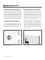
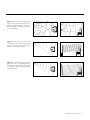
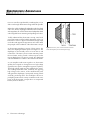
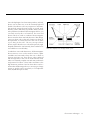
C L S IIz
TM
u s e r ’ s
c
l
m a n u a l
s
e
l
e
c
t
r
MA R T I N LOGA N
o
s
t
a
t
i
c
CONTENTS
Contents . . . . . . . . . . . . . . . . . . . . . . . . . . . . . . . . . . . . . .2
Installation in Brief . . . . . . . . . . . . . . . . . . . . . . . . . . . . .3
Introduction . . . . . . . . . . . . . . . . . . . . . . . . . . . . . . . . . . .4
Operation . . . . . . . . . . . . . . . . . . . . . . . . . . . . . . . . . . . . .4
AC Power Connection
Signal Connection
Break-In
High-Frequency Softening Switch
Placement . . . . . . . . . . . . . . . . . . . . . . . . . . . . . . . . . . . . .6
Listening Position
The Wall Behind the Listener
The Wall Behind the Speakers
The Side Walls
Experimentation
Final Placement
The Extra “Tweak”
Enjoy Yourself
Room Acoustics . . . . . . . . . . . . . . . . . . . . . . . . . . . . . . . .8
Your Room
Terminology
Rules of Thumb
Dipolar Speakers and Your Room
Solid Footing
Dispersion Interactions . . . . . . . . . . . . . . . . . . . . . . . . .10
Controlled Horizontal Dispersion
Controlled Vertical Dispersion
Three Major Types of Dispersion
Electrostatic Advantages . . . . . . . . . . . . . . . . . . . . . . . .12
Full Range Operation
MartinLogan Exclusives . . . . . . . . . . . . . . . . . . . . . . . . .15
Curvilinear Line Source
Vapor Deposited Film
Transducer Integrity
Electrostatic Loudspeaker History . . . . . . . . . . . . . . . .16
Frequently Asked Questions . . . . . . . . . . . . . . . . . . . . .18
Troubleshooting . . . . . . . . . . . . . . . . . . . . . . . . . . . . . . .20
General Information . . . . . . . . . . . . . . . . . . . . . . . . . . .21
Specifications
Warranty and Registration
Service
Glossary of Audio Terms . . . . . . . . . . . . . . . . . . . . . . . .22
The lightning bolt flash with arrowhead symbol, within
an equilateral triangle, is intended to alert the user to
the presence of uninsulated “dangerous voltage” within the
product’s enclosure that may be of sufficient magnitude
to constitute a risk of electric shock.
The exclamation point within an equilateral triangle is
intended to alert the user to the presence of important
operating and maintenance (servicing) instructions in
the literature accompanying the appliance.
2
Contents
INSTALLATION
We know you are eager to hear your new CLS IIz loudspeakers,
so this section is provided to allow fast and easy set up.
Once you have them operational, please take the time to
read, in depth, the rest of the information in this manual.
It will give you perspective on how to attain the greatest
possible performance from this most exacting transducer.
If you should experience any difficulties in the setup or
operation of your CLS IIz speakers, please refer to the Room
Acoustics, Placement or Operation sections of this manual.
Should you encounter a persistent problem that cannot be
resolved, please contact your authorized MartinLogan dealer.
They will provide you with the appropriate technical analysis
to alleviate the situation.
WARNING!
•Hazardous voltages exist inside—do not
remove cover
•Refer servicing to a qualified technician
•To prevent fire or shock hazard, do not
expose this module to moisture
•Turn amplifier off and unplug speaker
should any abnormal conditions occur
•Do not operate if there is any visual
damage to the electrostatic panel element
•Do not over drive speaker beyond its rated power
Step 1: Unpacking
Remove your new CLS IIz speakers from their packing.
Carefully lean one transducer against a wall with the
curved portion of the speaker resting against a wall.
Step 2: Connection
Do not connect the AC power cords to your electronics
modules yet!
Move the electronics module close to the transducer frame.
Firmly insert the high voltage connector from the electrostatic transducer into the matching socket near the front of
the electronics module.
IN
BRIEF
washers. Please start the cap screws by hand to prevent
stripping then tighten with the provided Allen head tool.
Step 4: Install the Adjustable Feet
Attach the enclosed feet to the bottom of the wooden
transducer frame and electronics by threading into the
metal inserts located in the bottom of each. These feet
allow you to adjust the vertical ‘tilt’ of the speaker system.
Step 5: Placement
Place each CLS IIz at least two feet from any wall and angle
them slightly toward your listening area. This is a good
place to start. Please see the Placement section (pages 6–7)
of this manual for more details.
Step 6: Power Connection (AC) (see warning)
MartinLogan speakers require AC power to energize their
electrostatic cells. Using the AC power cords provided, plug
them in first to the AC power receptacle on the rear panel of
the speaker, making sure that you have made a firm connection, and then to the wall outlet. Please see the Operation
section (pages 4–5) of this manual for more details.
Step 7: Signal Connection
Use the best speaker cables you can. Higher quality cables,
available from your specialty dealer, are recommended
and will give you superior performance. Spade connectors
are suggested for optimum contact and ease of installation.
Attach your speaker cables to the Signal Input section on
the rear panel. Be consistent when connecting speaker
leads to the terminals on the back of the CLS IIz: take great
care to assign the same color to the (+) terminal on both
the left and right channels. If bass is nonexistent and you
cannot discern a tight, coherent image, you may need
to reverse the (+) and (–) leads on one side to bring the
system into proper polarity.
Step 8: Listen and Enjoy
Now, you may turn on your system and enjoy!
Step 3: Attach Electronics Module
Now attach the electronics module to the wooden transducer frame using the Allen head cap screws and finish
Installation in Brief
3
INTRODUCTION & OPERATION
Introduction
Congratulations! You have invested in one of the world’s
premier loudspeaker systems.
The MartinLogan CLS IIz represents the culmination of an
intensive, dedicated group research program directed
toward establishing a world class reference monitor
utilizing leading-edge technology, without compromising
durability, reliability, craftsmanship or aesthetic design.
The result of cumulative technology gleaned from previous
research and development projects, the CLS IIz represents the
latest developments in electrostatic loudspeaker technology.
The materials in your new CLS IIz speakers are of the highest
quality and will provide years of enduring enjoyment and
deepening respect. All wood pieces are constructed from
selected hardwoods. They are grain and color matched and
finally hand finished.
Through rigorous testing, the curvilinear electrostatic panel
has proven itself to be one of the most durable and reliable
transducers available today. Fabricated from a custom tool
punched high-grade steel, the patented panel is then coated
with a special polymer that is applied via a proprietary
electrostatic deposition process. This panel assembly houses
a membrane just 0.0005 of an inch thick. Ruggedly constructed and insulated, as much as 200 watts of continuous
power has driven the CLS IIz’s energized diaphragm into
massive excursions with no deleterious effects.
The other sections of your User’s Manual will explain
in detail the operation of your CLS IIz speakers and the
philosophy applied to their design. A clear understanding
of your speakers will insure that you obtain maximum performance and pleasure from this most exacting transducer.
It has been designed and constructed to give you years of
trouble-free listening enjoyment.
4
Introduction & Operation
AC Power Connection
Because your MartinLogan CLS IIz’s use an internal power
supply to energize their electrostatic cells with high-voltage DC, they must be connected to an AC power source.
For this reason they are provided with the proper IEC standard
power cords. These cords should be firmly inserted into the
AC power receptacles on the rear connection panel of the
speakers, then to any convenient AC wall outlet. The CLS IIz’s
integrate a signal-sensing power supply which will switch
off after a few minutes of no music signal and requires less
than two seconds to recharge the panels when a music signal
is present.
Your CLS IIz speakers are wired for the power service supplied in the country of original consumer sale. The AC
power rating applicable to a particular unit is specified
both on the packing carton and on the serial number plate
attached to the speaker.
If you remove your CLS IIz speakers from the country
of original sale, be certain that AC power supplied in any
subsequent location is suitable before connecting and
operating the speakers. Substantially impaired performance
or severe damage may occur to a CLS IIz speaker if operation is attempted from an incorrect AC power source.
WARNING! The power cord should not be installed,
removed, or left detached from the speaker while
the other end is connected to an AC power source.
Signal Connection
Use the best speaker cables you can. The length and type of
speaker cable used in your system will have an audible
effect. Under no circumstance should a wire of gauge higher
(thinner) than #16 be used. In general, the longer the length
used, the greater the necessity of a lower gauge, and the
lower the gauge, the better the sound, with diminishing
returns setting in around #8 to #12.
OPERATION
Break-In
A variety of speaker cables are now available whose
manufacturers claim better performance over standard
heavy gauge wire. We have verified this in many cases, and
the improvements available are often more noticeable
than the differences between wires of different gauge. The
effects of cables may be masked if the equipment is not of
the highest quality.
We also recommend, if possible, that short runs of speaker
cable connect the power amplifier(s) and speakers and that
high-quality long interconnect cables be used to connect
the preamplifier and power amplifier. This results in the
power amplifiers being close to the speakers, which may
be practically or cosmetically difficult, but if the length of
the speaker cables can be reduced to a few meters, sonic
advantages may be obtained.
Connections are made at the Signal Input section on the
rear electronics panel of the CLS IIz. Use spade connectors
for optimum contact and ease of installation. Make certain
that all of your connections are tight.
Be consistent when connecting the speaker cables to the
Signal Input terminals. Take care to assign the same color
cable lead to the (+) terminal on both the left and right
channel speakers. If bass is nonexistent and you cannot
discern a tight, coherent image, you may need to reverse
the (+) and (–) leads on one speaker to bring the system
into proper polarity.
When you first begin to play your CLS IIz speakers allow
90 hours of break-in at 90 dB (moderate listening levels)
before any critical listening. The CLS will benefit from the
initial break in process like any conventional driver. The
membrane will flex and become more supple resulting in a
richer, more detailed and accurate sound quality compared
to the initial, out of the box, performance. Typically the bulk
of the break-in will occur in the first 90 hours but subtle
improvements will continue for quite some time.
High-Frequency Softening Switch
On the rear panel of the CLS IIz electronics module, near
the signal input, is a two position High Frequency Softening
switch that allows you to select the type of high frequency
response that you desire.
The ‘Flat’ position is considered the normal setting for
most rooms. However, due to different listening environments, different electronics characteristics and personal
preferences, you may prefer the ‘Soft’ Position. We suggest that you listen to the speaker using both switch
positions and decide which position is correct for you particular situation.
WARNING! Turn your amplifier off before making
or breaking any signal connections!
Operation
5
PLACEMENT
Listening Position
By now your speakers should be placed approximately
two to three feet from the front wall, the wall in front of
the listening position, and at least one to two feet from the
side walls. Your sitting distance should be farther than the
distance between the speakers themselves. What you are
trying to attain is the impression of good center imaging
and stage width.
There is no exact distance between speakers and listener,
but there is a relationship. In long rooms, naturally, that
relationship changes. The distance between the speakers
will be far less than the distance from you to the speaker
system. However, in a wide room, you will still find that if
the distance from the listener to the speakers becomes
smaller than the distance between the speakers themselves,
the image will no longer focus in the center.
Now that you have positioned your speaker system, spend
some time listening. Wait to make any major changes in
your initial setup for the next few days as the speaker
system itself will change subtly in its sound. Over the first
40 hours of play the actual tonal quality will change slightly
with deeper bass and more spacious highs resulting.
After a few days of listening you can begin to make refinements and hear the differences of those refinements.
The Wall Behind the Listener
Near-field reflections can occur from your back wall, the
wall behind the listening position. If your listening position
is close to the back wall, these reflections can cause problems
and confuse the quality of imaging. Actually it is better for
the wall behind you to be soft than to be bright. If you
have a hard back wall and your listening position is close
to it, experiment with devices that will soften and absorb
information (i.e., wall hangings and possibly even sound
absorbing panels).
The Wall Behind the Speakers
The front surface, the wall behind your speakers, should not
be extremely hard or soft. For instance, a pane of glass
will cause reflections, brightness and confused imaging.
Curtains, drapery and objects such as bookshelves can
be placed along the wall to soften a hard surface. A standard
6
Placement
sheet rock or textured wall is generally an adequate
surface if the rest of the room is not too bright and hard.
Sometimes walls can be too soft. If the entire front wall
consists of only heavy drapery, your system can sound too
soft or dull. You may hear dull, muted music with little
ambience. Harder room surfaces will actually help in this case.
The front surface should, optimally, be one long wall
without any doors or openings. If you have openings, the
reflection and bass characteristics from one channel to the
other can be different.
The Side Walls
The same requirements exist for side walls. Additionally, a
good rule of thumb is to have the side walls as far away
from the speaker sides as possible, minimizing near-field
side wall reflections. Sometimes, if the system is bright or
the imaging is not to your liking, and the side walls are
very near, try putting curtains or softening material directly
to the edge of each speaker. An ideal side wall, however,
is no side wall at all.
Experimentation
Toe-in
Now you can begin to experiment. First begin by toeing your
speakers in towards the listening area and then facing them
straight into the room. You will notice that the tonal balance
changes slightly. You will also notice the imaging changing.
Generally it is found that the ideal listening position is with
the speakers slightly toed-in so that you are listening to the
inner third of the curved transducer section.
Experimenting with the toe-in will help in terms of tonal
balance. You will notice that as the speakers are toed-out,
the system becomes slightly brighter than when toed-in.
This design gives you the flexibility to compensate for a
soft or bright room.
Tilting the Speakers Backwards and Forwards
As can be seen from the diagrams in the Room Acoustics
section of this manual (pages 10–11), the vertical dispersion
is directional above and below the stator panel itself. In some
instances, if you are sitting close to the floor, slight forward
tilting of the speakers can enhance clarity and precision.
Imaging
In their final location, your CLS IIz’s should have a stage width
somewhat wider than the speakers themselves. On wellrecorded music, the instruments should extend beyond
the edges of each speaker to the left and to the right, yet a
vocalist should appear directly in the middle. The size of
the instruments should be neither too large nor too
small. Additionally, you should find good clues as to stage
depth. Make sure that the vertical alignment, distance
from the front wall, and toe-in, is exactly the same from
one speaker to the other. This will greatly enhance the
quality of your imaging.
Bass Response
Your bass response should neither be one note nor too
heavy. It should extend to even the deepest organ passages, yet it should be tight and well defined. Kick-drums
should be tight and percussive—string bass notes should
be uniform and consistent throughout the entirety of the
run without any booming or thudding.
Tonal Balance
Voices should be natural and full, cymbals should be
detailed and articulate yet not bright and piercing, pianos
should have a nice transient characteristic and deep tonal
registers as well. If you cannot attain these virtues, read the
section on Room Acoustics (pages 10–11). This will give
you clues on how to get closer to those ideal virtues.
Final Placement
After obtaining good wall treatments and attaining proper
angle, begin to experiment with the distance from the wall
behind the speakers. Move your speaker slightly forward
into the room. What happened to the bass response?
What happened to the imaging? If the imaging is more
open and spacious and the bass response is tightened, that
is a superior position. Move the speakers back six inches
from the initial setup position and again listen to the imaging
and bass response. There will be a position where you will
have pinpoint imaging and good bass response. That position
is the point of the optimal placement from the front wall.
Now experiment with placing the speakers farther apart.
As the speakers are positioned farther apart, listen again,
not so much for bass response but for stage width and
good pinpoint focusing.
Your ideal listening position and speaker position will
be determined by:
•Tightness and extension of bass response
•Width of the stage
•Pinpoint focusing of imaging
Once you have determined the best of all three of these
considerations, you will have your best speaker location.
The Extra “Tweak”
A major cable company developed the following procedure
for speaker placement. As a final test of exact placement,
use these measurements for your speakers placement, and
see what can happen to the ultimate enhancement of
your system’s performance. These two basic formulas will
determine optimum placement of your speakers to minimize
standing waves.
1. Distance from the front wall (the wall in front of the listening
position) to the center of the curvilinear transducer. To
determine distance from the front wall, measure the height
of your ceiling (inches) and multiply the figure by 0.618
(i.e., ceiling height in inches x 0.618 = the distance from
the front wall to the center of the curvilinear transducer).
2. Distance from the side-walls to the center of the curvilinear
transducer. To determine distance from the side walls,
measure the width of your room (inches) and divide by
18. Next, multiply the quotient by 5 (i.e., room width in
inches/18 x 5 = the distance from the side-walls to the
center of the curvilinear transducer).
Enjoy Yourself
The CLS IIz is a very refined speaker and benefits from care
in setup. With these tips in mind you will find, over your
months of listening, that small changes can result in
measurable differences. As you live with your speakers, do
not be afraid to experiment with their positioning until
you find the optimal relationship between your room and
speaker system that gives to you the best results. Your efforts
will be rewarded.
You are now armed with the fundamental knowledge of
room acoustics and the specific fundamentals of the CLS IIz
loudspeaker. Happy listening!
Placement
7
ROOM ACOUSTICS
Your Room
This is one of those areas that requires both a little background to understand and some time and experimentation
to attain the best performance from your system.
Your room is actually a component and an important part
of your system. This component is a very large variable
and can dramatically add to, or subtract from, a great
musical experience.
All sound is composed of waves. Each note has its own
wave size, with the lower bass notes literally encompassing
from 10 feet to as much as 40 feet. Your room participates
in this wave experience like a three-dimensional pool with
waves reflecting and becoming enhanced depending on
the size of the room and the types of surfaces in the room.
Remember, your audio system can literally generate all of
the information required to recreate a musical event in
time, space and tonal balance. The purpose of your room,
ideally, is to not contribute to that information. However,
every room does contribute to the sound, and the better
speaker manufacturers have designed their systems to
accommodate this phenomenon.
Let’s talk about a few important terms before we begin.
Terminology
Standing Waves
The parallel walls in your room will reinforce certain notes
to the point that they will sound louder than the rest of the
audio spectrum and cause “one-note bass”, “boomy bass”
or “tubby bass”. For instance, 100Hz represents a 10 feet
wavelength. Your room will reinforce that specific frequency if one of the dominant dimensions is 10 feet. Large
objects in the room such as cabinetry or furniture can help to
minimize this potential problem. Some serious “audiophiles”
will literally build a special room with no parallel walls just
to help eliminate this phenomenon.
Reflective Surfaces (near-field reflections)
The hard surfaces of your room, particularly if close to your
speaker system, will reflect some waves back into the room
over and over again, confusing the clarity and imaging of
your system. The smaller sound waves are mostly affected
here, and occur in the mid and high frequencies. This is
where voice and frequencies as high as the cymbals occur.
8
Room Acoustics
Resonant Surfaces and Objects
All of the surfaces and objects in your room are subject to
the frequencies generated by your system. Much like an
instrument, they will vibrate and “carry on” in syncopation
with the music, and contribute in a negative way to the
music. Ringing, boominess, and even brightness can occur
simply because they are “singing along” with your music.
Resonant Cavities
Small alcoves or closet type areas in your room can be
chambers that create their own “standing waves” and can
drum their own “one-note” sounds.
Clap your hands. Can you hear an instant echo respond back?
You have near-field reflections. Stomp your foot on the floor.
Can you hear a “boom”? You have standing waves or large
panel resonances such as a poorly supported wall. Put your
head in a small cavity area and talk loudly. Can you hear a
booming? You’ve just experienced a cavity resonance.
Rules of Thumb
Hard vs. Soft Surfaces
If the front or back wall of your listening room is soft, it
might benefit you to have a hard or reflective wall in
opposition. The ceiling and floor should follow the same
basic guideline as well. However, the side walls should be
roughly the same in order to deliver a focused image.
This rule suggests that a little reflection is good. As a matter
of fact, some rooms can be so “over damped” with carpeting,
drapes and sound absorbers that the music system can
sound dull and lifeless. On the other hand, rooms can be
so hard that the system can sound like a gymnasium with
too much reflection and brightness. The point is that balance
is the optimum environment.
Breakup Objects
Objects with complex shapes, such as bookshelves, cabinetry and multiple-shaped walls can help break up those
sonic gremlins and diffuse any dominant frequencies.
Solid Coupling
Your loudspeaker system generates frequency vibrations
or waves into the room. This is how it creates sound.
Those vibrations will vary from 20 per second to 20,000
per second. If your speaker system is not securely planted
Solid Footing
on the floor or solid surface, it can shake as it produces
sound and, consequently, the sound can be compromised.
If your speaker is sitting on the carpet and only foot gliders
are used, the bass can be ill defined and even boomy. The
use of spikes is recommended to insure secured footing for
your speakers. (See Solid Footing, this page, for spike information and installation instructions).
Dipolar Speakers and Your Room
MartinLogan electrostatic loudspeakers are known as dipolar
radiators. This means that they produce sound from both
their fronts and their backs. Consequently, musical information is reflected by the wall behind them and may arrive
either in or out of step with the information produced by
the front of the speaker.
The low frequencies can either be enhanced or nulled by
the position from the front wall. Your CLS IIz’s have been
designed to be placed two to three feet from the front wall
(the wall in front of the listening position) to obtain the
best results; however, your room may see things differently.
So listening to the difference of the bass response as a
result of the changes in distance from the front wall can
allow you to get the best combination of depth of bass
and tonal balance.
Now that you know about reflective surfaces and resonant
objects, you can see how the midrange and high frequencies
can be affected. The timing of the initial wave as it radiates
to your ears, and then the reflected information as it arrives
at your ears later in time, can result in confusion of the precious timing information that carries the clues to imaging.
Consequently the result is blurred imaging and excessive
brightness. Soft walls, curtains, wall hangings, or sound
dampeners (your dealer can give you good information
here) can be effective if these negative conditions occur.
After living and experimenting with your CLS IIz’s, you may
want to use ETC (Energy Transfer Coupler) Spikes (See
Figure 1), which are available from your local MartinLogan
dealer or on our website at www.martinlogan.com. With
the use of these spikes, the CLS IIz will become more firmly
planted on the floor and, consequently, bass will tighten and
imaging will become more coherent and detailed. It is
best not to implement the spikes, however, until you are
secure in the positioning, as the spikes can damage the floor
if the speaker is moved. MartinLogan ETC spikes will fit
any common 1/4 inch thread insert that may be found on
your other audio equipment (racks, speakers, etc.).
Spike Installation Instructions:
1. Carefully lay your speaker on its side to gain access to
the bottom.
2. Remove existing feet or spikes. Thread new spikes into
holes and screw them in all of the way.
3. Tighten jam nut snugly by hand. Do not over tighten
the nut.
4. Right the speaker.
Caution: Make sure your hands and any cabling are clear
of the spikes. Do not slide speaker as spikes are sharp and
can damage your floor or carpet.
5. Adjust to level by rotating spikes. Tighten the jam nut
securely when satisfied that speaker is level.
Caution: Walking the speaker may result in a broken spike.
Figure 1. The ETC Spike.
Room Acoustics
9
DISPERSION INTERACTIONS
Controlled Horizontal Dispersion
Your CLS IIz’s launch a 30-degree dispersion pattern when
viewed from above. This horizontal dispersion field gives a
choice of good seats for the performance while minimizing
interactions with side walls (See Figure 2). Make sure both
speakers stand exactly at the same vertical angle, otherwise
the image can be skewed or poorly defined. The wave
launch of both speakers is extremely accurate in both the
time and spectral domain. Consequently, small refined
adjustments can result in noticeable sonic improvements.
Controlled Vertical Dispersion
As you can see from the illustrations, your CLS IIz speakers
project a controlled dispersion pattern. Each CLS IIz is a 4foot line source beginning a few inches above the floor
level (See Figure 3). This vertical dispersion profile minimizes interactions with the floor and the ceiling.
Figure 2. MartinLogan CLS IIz’s deliver a 30-degree wave launch dispersion
pattern distributed horizontally.
10
Dispersion Interactions
Three Major Types of Dispersion
In the field of loudspeaker design, it is a known fact that as
the sound wave becomes progressively smaller than the
transducer producing it, the dispersion of that wave
becomes more and more narrow, or directional. This fact
occurs as long as the transducer is a flat surface. Large flatpanel speakers exhibit venetian blind effects due to this
phenomenon. This is why most manufacturers opt for
small drivers (i.e., tweeters and midrange) to approximate
what is known as a point source wave launch.
Historically, most attempts to achieve smooth dispersion
from large flat-panel transducers resulted in trade-offs.
After exhaustive testing of these different solution attempts,
we found an elegantly simple, yet very difficult to execute
solution. By curving the radiating surface, we create the
effect of a horizontal arc. This allows the engineers at
MartinLogan to control the high frequency dispersion
pattern of our transducers. That is why you see the gentle
curve on our products.
Figure 3. Your CLS IIz speaker system is a 48 inch line source viewed vertically.
Figure 4– 5. As can be seen here, point source
concepts invite a great deal of room interaction.
While delivering good frequency response to a
large listening audience, imaging is consequently
confused and blurred.
Figure 6–7. Even though they suffer from
“venetian blind” effect, angled multiple panel
speakers can deliver good imaging, but only
to specific spots in the listening area.
Figure 8–9. A controlled 30-degree cylindrical
wave-front, which is a MartinLogan exclusive,
offers optimal sound distribution with minimal
room interaction. The result is solid imaging with
a wide listening area.
Dispersion Interactions
11
ELECTROSTATIC ADVANTAGES
How can sound be reproduced by something that you are
able to see through? Electrostatic energy makes this possible.
Where the world of traditional loudspeaker technology deals
with cones, domes, diaphragms and ribbons that are moved
with magnetism, the world of electrostatic loudspeakers deals
with charged electrons attracting and repelling each other.
To fully understand the electrostatic concept, some background information will be helpful. Remember when you
learned in a science or physics class that like charges repel
each other and opposite charges attract each other? Well,
this principle is the foundation of the electrostatic concept.
An electrostatic transducer consists of three pieces: the
stators, the diaphragm and the spacers (See Figure 11). The
diaphragm is what actually moves to excite the air and
create music. The stator’s job is to remain stationary, hence
the word stator, and to provide a reference point for the
moving diaphragm. The spacers provide the diaphragm
with a fixed distance in which to move between the stators.
As your amplifier sends music signals to an electrostatic
speaker, these signals are changed into two high-voltage
signals that are equal in strength but opposite in polarity.
These high voltage signals are then applied to the stators.
The resulting electrostatic field, created by the opposing
high voltage on the stators, works simultaneously with
and against the diaphragm, consequently moving it back
and forth, producing music. This technique is known as
push-pull operation and is a major contributor to the sonic
purity of the electrostatic concept due to its exceptional
linearity and low distortion.
12
Electrostatic Advantages
Figure 11. Cut-away view of an electrostatic transducer.
Notice the simplicity due to minimal parts usage.
Since the diaphragm of an electrostatic speaker is uniformly
driven over its entire area, it can be extremely light and
flexible. This allows it to be very responsive to transients,
thus perfectly tracing the music signal. As a result, great
delicacy, nuance and clarity are possible. When you look
at the problems of traditional electromagnetic drivers, you
can easily see why this is so beneficial. The cones and
domes which are used in traditional electromagnetic
drivers cannot be driven uniformly because of their design.
Cones are driven only at the apex. Domes are driven at
their perimeter. As a result, the rest of the cone or dome
is just “along for the ride”. The very concept of these
drivers requires that the cone or dome be perfectly rigid,
damped and massless. Unfortunately, these conditions are
not available in our world today.
Figure 12. Cut-away view of a typical moving coil driver.
Notice the complexity due to the high number of parts.
To make these cones and domes move, all electromagnetic
drivers must use voice coils wound on formers, spider
assemblies and surrounds to keep the cone or dome in
position (See Figure 12). These pieces, when combined
with the high mass of the cone or dome materials used,
make it an extremely complex unit with many weaknesses
and potential for failure. These faults contribute to the
high distortion products found in these drivers and is a
tremendous disadvantage when you are trying to change
motion as quickly and as accurately as a loudspeaker
must (40,000 times per second!).
Electrostatic Advantages
13
Full Range Operation
The most significant advantage of MartinLogan’s exclusive
transducer technology reveals itself when you look at
examples of other loudspeaker products on the market today.
The CLS IIz uses no crossover networks because they are
not needed. The CLS IIz consists of a single, seamless electrostatic membrane reproducing all frequencies. How is
this possible?
First we must understand that music is not composed of
separate high, mid and low frequency pieces. In fact,
music is comprised of a single complex waveform with all
frequencies interacting simultaneously.
The electrostatic transducer of the CLS IIz essentially acts as
an exact opposite of the microphones used to record the
original event. A microphone, which is a single working
element, transforms acoustic energy into an electrical signal
that can be amplified or preserved by some type of storage
media. The CLS IIz’s electrostatic transducer transforms
electrical energy from your amplifier into acoustical energy.
Due to the limitations of electromagnetic drivers, no
single unit can reproduce the full range of frequencies.
Instead, these drivers must be designed to operate within
a narrow, fixed bandwidth of the frequency range, and then
combined electrically so that the sum of the parts equals
the total signal. While nice in theory, we must deal with
real-world conditions.
In order to use multiple drivers, a crossover network is
enlisted to attempt a division of the complex musical signal
into the separate pieces (usually highs, mids, and lows) that
each specific driver was designed to handle. Unfortunately,
due to the phase relationships that occur within all crossover
networks and during the acoustical recombination process,
nonlinearities and severe degradation of the music signal
take place in the ear’s most critical zone (See Figure 13).
The CLS IIz’s electrostatic transducer can single-handedly
reproduce all frequencies simultaneously. You have in one
transducer the ability to handle in elegant simplicity the
critical frequencies.
The crossover phase aberrations that are associated with
traditional tweeter, midrange, and woofer systems are
eliminated. The result is a dramatic improvement in imaging
and staging performance due to the minutely accurate phase
relationship of the full-range panel wave launch.
Conventional Loudspeaker
Tweeter
CLS IIz
crossover point (2–5kHz)
Critical Zone: 200Hz–20kHz
Midrange
crossover point (100–400Hz)
Woofer
14
Figure 13. This diagram illustrates how a conventional
speaker system must use multiple crossover networks
that have negative effects on the musical performance.
Electrostatic Advantages
ESL Panel
MARTINLOGAN EXCLUSIVES
Curvilinear Line Source (CLSTM)
Since the beginning of audio, achieving smooth dispersion
has been a problem for all loudspeaker designers. Largepanel transducers present even more of a challenge because
the larger the panel, the more directional the dispersion
pattern becomes.
Full range electrostats have long been one of the most
problematic transducers because they attain their full range
capabilities via a large surface area. It looked as if they
were in direct conflict to smooth dispersion and almost
every attempt to correct this resulted in either poor dispersion or a serious compromise in sound quality.
After extensive research, MartinLogan engineers discovered
an elegantly simple solution to achieve a smooth pattern of
dispersion without degrading sound quality. By curving the
horizontal plane of the electrostatic transducer, a controlled horizontal dispersion pattern could be achieved, yet
the purity of the almost massless electrostatic diaphragm
remained uncompromised. After creating this technology,
MartinLogan developed the production capability to bring
it out of the laboratory and into the market place.
You will find this proprietary MartinLogan technology used in
all of our products. It is one of the many reasons behind our
reputation for high-quality sound with practical usability.
This is also why you see the unique “see through” cylindrical shape of all MartinLogan products.
Vapor Deposited Film
The diaphragm material used in all MartinLogan speakers
employs an extremely sophisticated conductive surface
that has been vapor deposited on the polymer surface at
an atomic level. A proprietary compound is vaporized then
electrostatically driven into the surface of the polymer film
in a vacuum chamber. This process allows an optically
transparent surface adding no mass to the diaphragm that
is extremely uniform in its surface resistivity characteristics.
This uniform surface resistivity controls the electrostatic
charge on the diaphragm surface and regulates its migration.
As a result, no discharging or “arcing” can occur.
Transducer Integrity
All MartinLogan transducers begin with two pieces of
high-grade, cold rolled steel. These steel pieces are then
custom perforated and insulated with a unique composite
coating. This proprietary coating insulates the stator to
three times its actual needed working voltage and gives
the CLS IIz a wide margin of safe operation. In addition to
the electrical insulation properties, this coating also provides
the CLS IIz with a durable, attractive finish that dampens the
steel to prevent ringing. These pieces are then sandwiched
with our exclusive vapor deposited diaphragm and spacers
into a curved geometry and bonded together with aerospace
adhesives whose strength exceeds that of welding.
The result of these advanced technologies is a transducer that
is attractive, durable, highly rigid, well dampened and neutral.
MartinLogan Exclusives
15
ELECTROSTATIC LOUDSPEAKER HISTORY
In the late 1800s, any loudspeaker was considered exotic.
Today, most of us take the wonders of sound reproduction
for granted.
The outcome would dictate the way that future generations
would refer to loudspeakers as being either “conventional”
or “exotic”.
It was 1880 before Thomas Edison had invented the first
phonograph. This was a horn-loaded diaphragm that was
excited by a playback stylus. In 1898, Sir Oliver Lodge
invented a cone loudspeaker, which he referred to
as a “bellowing telephone”, that was very similar to the
conventional cone loudspeaker drivers that we know
today. However, Lodge had no intention for his device to
reproduce music because in 1898 there was no way to
amplify an electrical signal! As a result, his speaker had
nothing to offer over the acoustical gramophones of the
period. It was not until 1906 that Dr. Lee DeForrest
invented the triode vacuum tube. Before this, an electrical
signal could not be amplified. The loudspeaker, as we know
it today, should have ensued then, but it did not. Amazingly,
it was almost twenty years before this would occur.
Bell Laboratory’s electrostat was something to behold.
This enormous bipolar speaker was as big as a door.
The diaphragm, which was beginning to rot, was made of
a pig intestine that was covered with fine gold leaf to conduct
the audio signal.
When Rice and Kellogg began playing the new electrically
cut records through the electrostat, they were shocked
and impressed. The electrostat performed splendidly.
They had never heard instrumental timbres reproduced
with such realism. This system sounded like real music
rather than the honking, squawking rendition of the
acoustic gramophone. Immediately, they knew they were
on to something big. The acoustic gramophone was destined
to become obsolete.
Due to Rice and Kellogg’s enthusiasm, they devoted a
In 1921, the electrically cut phonograph record became a
considerable amount of time researching the electrostatic
reality. This method of recording was far superior to the
design. However, they soon encountered the same difficulties
mechanically cut record and possessed almost 30 dB of
that even present designers face; planar
dynamic range. The acoustical gramospeakers require a very large surface
phone couldn’t begin to reproduce all
Rice and Kellogg had
area to reproduce the lower frequencies
of the information on this new disc. As
narrowed the field of
of the audio spectrum. Because the
a result, further developments in loudspeakers were needed to cope with “contestants” down to the management at Bell Labs considered
large speakers unacceptable, Rice and
this amazing new recording medium.
cone and the electrostat.
Kellogg’s work on electrostatics would
never be put to use for a commercial product. Reluctantly, they
By 1923, Bell Telephone Laboratories made the decision
advised the Bell management to go with the cone. For the
to develop a complete musical playback system consisting
next 30 years, the electrostatic design lay dormant.
of an electronic phonograph and a loudspeaker to take
advantage of the new recording medium. Bell Labs
assigned the project to two young engineers, C.W. Rice
During the Great Depression of the 1930s, consumer audio
and E.W. Kellogg.
almost died. The new electrically amplified loudspeaker
never gained acceptance, as most people continued to
Rice and Kellogg had a well equipped laboratory at their
use their old Victrola-style acoustic gramophones. Prior to
disposal. This lab possessed a vacuum tube amplifier with
the end of World War II, consumer audio saw little,
an unheard of 200 watts, a large selection of the new
if any, progress. However, during the late 1940s, audio
electrically cut phonograph records and a variety of
experienced a great rebirth. Suddenly there was tremendous
loudspeaker prototypes that Bell Labs had been collecting
interest in audio products, and with that, a great demand
over the past decade. Among these were Lodge’s cone, a
for improved audio components. No sooner had the cone
speaker that used compressed air, a corona discharge (plasma)
become established than it was challenged by products
speaker, and an electrostatic speaker.
developed during this new rebirth.
After a short time, Rice and Kellogg had narrowed the field
of “contestants” down to the cone and the electrostat.
16
Electrostatic Loudspeaker History
In 1947, Arthur Janszen, a young Naval engineer, took part
around 70 watts. As a result, many people continued to
in a research project for the Navy. The Navy was interested
use box speakers with cones.
in developing a better instrument for testing microphone
arrays. The test instrument needed an extremely accurate
In the early 1960s Arthur Janszen joined forces with the
speaker, but Janszen found that the cone speakers of the
KLH loudspeaker company, and together they introduced
period were too nonlinear in phase and amplitude response
the KLH 9. Due to the large size of the KLH 9, it did not
to meet his criteria. Janszen believed that electrostats
have as many limitations as the Quad. The KLH 9 could
were inherently more linear than cones, so he built a model
play markedly louder and lower in frequency than the
using a thin plastic diaphragm treated with a conductive
Quad ESL. Thus a rivalry was born.
coating. This model confirmed Janszen’s
beliefs, for it exhibited remarkable phase
Janszen continued to develop electroThese developments allow
and amplitude linearity.
static designs. He was instrumental
the consumer to own the
in the design of the Koss Model One,
Janszen was so excited with the results
the Acoustech and the Dennesen
highest performance loudthat he continued research on the
speakers. Roger West, the chief
electrostatic speaker on his own time. speaker products ever built. designer of the JansZen Corporation,
He soon thought of insulating the stators to
became the president of Sound Lab.
prevent the destructive effects of arcing. By 1952, he had
When JansZen Corporation was sold, the RTR loudspeaker
an electrostatic tweeter element ready for commercial
company bought half of the production tooling. This tooling
production. This new tweeter soon created a sensation
was used to make the electrostatic panels for the Servostatic, a
among American audio hobbyists. Since Janszen’s tweeter
hybrid electrostatic system that was Infinity’s first speaker
element was limited to high frequency reproduction, it
product. Other companies soon followed; each with their
often found itself used in conjunction with woofers, most
own unique applications of the technology. These include
notably, woofers from Acoustic Research. These systems
Acoustat, Audiostatic, Beverage, Dayton Wright, Sound
were highly regarded by all audio enthusiasts.
Lab and Stax, to name a few.
As good as these systems were, they would soon be
surpassed by another electrostatic speaker.
In 1955, Peter Walker published three articles on electrostatic
loudspeaker design in Wireless World, a British electronics
magazine. In these articles, Walker demonstrated the benefits
of the electrostatic loudspeaker. He explained that electrostatics
permit the use of diaphragms that are low in mass, large in
area and uniformly driven over their surfaces by electrostatic
forces. Due to these characteristics, electrostats have the
inherent ability to produce a wide bandwidth, flat frequency
response with distortion products being no greater than the
electronics driving them.
By 1956, Walker backed up his articles by introducing a
consumer product, the now famous Quad ESL. This speaker
immediately set a standard of performance for the audio
industry due to its incredible accuracy. However, in actual
use, the Quad had a few problems. It could not be played
very loud, it had poor bass performance, it presented a
difficult load that some amplifiers did not like, its dispersion
was very directional and its power handling was limited to
Electrostatic speakers have progressed and prospered
because they actually do what Peter Walker claimed they
would. The limitations and problems experienced in the
past were not inherent to the electrostatic concept. They
were related to the applications of these concepts.
Today, these limitations have been addressed. Advancements
in materials due to the U.S. space program give designers
the ability to harness the superiority of the electrostatic
principle. Today’s electrostats use advanced insulation
techniques or provide protection circuitry. The poor dispersion
properties of early models have been addressed by using
delay lines, acoustical lenses, multiple panel arrays or, as in
our own products, by curving the diaphragm. Power handling
and sensitivity have also been increased.
These developments allow the consumer the opportunity to
own the highest performance loudspeaker products ever
built. It’s too bad Rice and Kellogg were never able
to see just how far the technology would be taken.
Electrostatic Loudspeaker History
17
FREQUENTLY ASKED QUESTIONS
How do I clean my speakers?
Just use a dust free cloth or a soft brush to remove the
dust from your speakers. We recommend a specialty cloth
(available through the Xtatic shop at www.martinlogan.com)
that cleans your speakers better than anything else we
have ever tried. Do not spray any kind of cleaning
agent on or in close proximity to the electrostatic
element.
What is the advantage of ESL?
Since the polyester film diaphragm is uniformly driven
over its entire surface—unlike a tweeter that is only driven
at its edges—it is the only technology that can be made
large enough to play bass, yet is still light enough for
high frequencies. This unique property allows for the
elimination of high frequency crossover points and
their associated distortions.
What size amplifier should I use?
We recommend an amplifier with 100 to 200 watts per
channel for most applications. Probably less would be
adequate for our smaller hybrids or when used in home
theater where a subwoofer is employed. Our hybrid
designs will perform well with either a tube or transistorized
amplifier, and will reveal the sonic character of either
type. However, it is important that the amplifier be stable
operating into varying impedance loads: a stable amplifier
will be able to deliver twice its rated wattage into 4 Ohms
and should again double into 2 Ohms.
Could you suggest a list of suitable electronics and
cables that would be ideal for MartinLogan speakers?
The area of electronics and cable choice is probably
the most common type of question that we receive. It is
also the most subjective. We have repeatedly found
that brands that work well in one setup will drive someone
else nuts in another. We use many brands with great
success. Again, we have no favorites; we use electronics
and cables quite interchangeably. We would suggest
listening to a number of brands—and above all else,
trust your ears. Dealers are always the best source for
information when purchasing additional audio equipment.
18
Frequently Asked Questions
Is there likely to be any interaction between my speakers
and the television in my Audio/Video system?
Actually, there is less interaction between a television and
an electrostatic speaker than between a television and a
conventional system. You will find the CLS IIz does not
degrade your televisions picture, even if placed directly
beside your television.
Will my electric bill go ‘sky high’ by leaving my speakers plugged in all the time?
No. A pair of MartinLogans will draw about 5 watts
maximum. There is some circuitry to turn off the static
charge when not in use; however, the actual consumption
will remain close to the same. The primary purpose of
the sensing circuitry is to prevent dust collection on the
electrostatic element.
If the diaphragm is punctured with a pencil, stick, or
similar item, how extensive would the damage to the
speaker be?
Our research department has literally punctured hundreds
of holes in a diaphragm, neither affecting the quality of
the sound nor causing the diaphragm to rip. However,
you will be able to see the actual puncture and it can
be a physical nuisance. If this is the case, replacing the
electrostatic transducer will be the only solution.
Will exposure to sunlight affect the life or performance
of my speakers?
We recommend that you not place any loudspeaker in
direct sunlight, as the ultraviolet (UV) rays from the sun
can cause deterioration of grill cloth, speaker cones,
etc. Small exposures to UV will not cause a problem.
In general, the filtering of UV rays through glass will
greatly reduce the negative effects on the electrostatic
membrane itself.
Will excessive smoke or dust cause any problems with
my electrostatic speakers?
Exposure to excessive contaminants such as smoke
or dust may potentially affect the performance of the
electrostatic membrane, and may cause discoloration
of the diaphragm membrane. When not in use for
extended periods, you should unplug the speakers and
cover them with the plastic bags in which the speakers
were originally packed.
It is a good idea to vacuum the electrostatic portion of
each speaker once or twice a year. This will be most
effective if the speaker has been unplugged for six
hours or overnight. You need not worry about the vacuum
pressure damaging the "delicate" membrane. It is
extraordinarily durable.
A problem has recently developed with my MartinLogan
speakers. The right speaker seems to be hissing even
when the amplifier and such are not connected. I was
wondering if this sounds like any problem you have
encountered previously and have a simple solution for
or might it be something which will need to be looked
into more carefully.
Your speakers are dusty. The electrostatic charge on
the element has attracted some airborne dust or pollen.
First unplug the speakers for six hours or overnight.
This will allow the charge to dissipate. Now vacuum
the front of the panel with a very strong vacuum.
Don’t worry about damaging the membrane. You won’t.
This should take care of your problem.
By the way, since 1993, all of our speakers have been
built with a charging circuit board that only charges the
electrostatic element when music plays. At other times
they are not charged, and cannot collect dust. You can get
the same benefit by simply unplugging them whenever
they are not in use. An easy way to do that is with a
power strip that has a switch.
Could my children, pets, or myself be shocked by the
high-voltage present in the electrostatic panel?
No. High voltage with low current is not dangerous. As a
matter of fact, the voltage in our speakers is 10 times
less than the static electricity that builds up on the surface
of your television screen.
How do MartinLogan speakers hold up over a long term
in the humidity of tropical climates?
We should tell you that MartinLogan indeed has a very
substantial number of customers in tropical regions of
the world. Our speakers have been serving them nicely for
many years. This concern may have come from our earlier
design of speakers, which were charged continuously.
Since 1993, all of our speakers have been designed so that
they only charge the panel while music is being played.
This improvement has made a tremendous difference
in the consistent performance of our product. There may
be a little more maintenance involved in humid regions
when not in an air conditioned environment. Simply
enough, the concern is to keep the electrostatic panels
dust free. Humidity will combine with any dust on the
panel to make it slightly conductive. This will result in a
slight pathway for the charge to leave the membrane of
the speaker. The solution is simple. They only require
occasional vacuuming with a strong vacuum hose. You
will have best results when the speakers have been
unplugged for six hours or overnight. We are confident
that they will serve you very well.
Should I unplug my speakers during a thunderstorm?
Yes, or before. It’s a good idea to disconnect all of your
audio/video components during stormy weather.
Frequently Asked Questions
19
TROUBLESHOOTING
No Output
•Check that all your system components are turned on.
•Check your speaker wires and connections.
•Check all interconnecting cables.
Weak Output, Loss of Highs
•Check the power cord. Is it properly connected to the speaker?
Exaggerated Highs, Brightness
•Check the toe-in of the speakers. Read Placement (pages 8–9)
for more information.
Muddy Bass
•Check placement. Try moving the speakers closer to the
front and side walls.
•Check the type of feet that are being used. Try attaching
the coupling spikes.
20
Troubleshooting
Lack of Bass
•Check your speaker wires. Is the polarity correct?
Poor Imaging
•Check placement. Are both speakers the same distance
from the walls? Do they have the same amount of
toe-in? Try moving the speakers away from the back
and side walls.
•Check the polarity of the speaker wires. Are they
connected properly?
Popping and Ticking Sounds, Funny Noises
•These occasional noises are harmless and will not hurt your
audio system or your speakers. All electrostatic speakers
are guilty of making odd noises at one time or another.
•These noises may be caused by dirt and dust particles
collecting on the speaker, by high humidity, or by AC
line fluctuations that may occur in your area.
•Dirt and dust may be vacuumed off with a brush attachment
connected to your vacuum cleaner, or you may blow
them off with compressed air.
GENERAL INFORMATION
Specifications
The CLS IIz hybrid speaker system consists of a broadrange single-element electrostatic transducer integrated
with a quick-response woofer. This approach takes advantage of the benefits that both technologies have to offer.
Dispersion is a controlled 30 degrees. This was achieved
by curving the electrostatic transducer element itself, an
elegantly simple solution.
System Frequency Response
35–20,000 Hz ± 3 dB
Dispersion
Horizontal: 30 Degrees
Vertical: 48 inch (122 cm) Line Source
Sensitivity
86 dB/2.83 volts/meter
Impedance
Nominal: 4 ohms
Minimum: 1.5 ohms @ 20 kHz
Components
Dual custom-wound audio transformer, polypropylene
capacitors
Power Handling
200 watts per channel
Recommended Amplifier Power
80 –200 watts per channel
Weight
85 lbs. each (38.5 kg)
Size
28 inches W × 14.5 inches D × 57.5 inches H
(71.1 cm W × 36.8 cm D × 146 cm H)
Warranty and Registration
Your CLS IIz speakers are provided with an automatic Limited
90-Day Warranty coverage.
You have the option, at no additional charge, to receive a
Limited 5-Year Warranty coverage. To obtain the Limited
5-Year Warranty coverage you need to complete and return
the Certificate of Registration, included with your speakers,
and provide a copy of your dealer receipt, to MartinLogan
within 30 days of purchase.
MartinLogan may not honor warranty service claims unless
we have a completed Warranty Registration card on file!
If you did not receive a Certificate of Registration with
your new CLS IIz speakers you cannot be assured of having
received new units. If this is the case, please contact your
authorized MartinLogan dealer.
Service
Should you be using your MartinLogan product in a country
other than the one in which it was originally purchased,
we ask that you note the following:
1. The appointed MartinLogan distributor for any given
country is responsible for warranty servicing only on
units distributed by or through it in that country in
accordance with its applicable warranty.
2. Should a MartinLogan product require servicing in a
country other than the one in which it was originally
purchased, the end user may seek to have repairs performed
by the nearest MartinLogan distributor, subject to that
distributor’s local servicing policies, but all cost of
repairs (parts, labor, transportation) must be born by
the owner of the MartinLogan product.
3. If, after owning your speakers for six months, you
relocate to a country other than the one in which
you purchased your speakers, your warranty may be
transferable. Contact MartinLogan for details.
General Information
21
GLOSSARY
OF
AUDIO TERMS
AC. Abbreviation for alternating current.
DC. Abbreviation for direct current.
Active crossover. Uses active devices (transistors, ICs, tubes)
and some form of power supply to operate.
Diffraction. The breaking up of a sound wave caused by
some type of mechanical interference such as a cabinet
edge, grill frame or other similar object.
Amplitude. The extreme range of a signal. Usually measured
from the average to the extreme.
Arc. The visible sparks generated by an electrical discharge.
Bass. The lowest frequencies of sound.
Bi-Amplification. Uses an electronic crossover, or line-level
passive crossover, and separate power amplifiers for the
high and low frequency loudspeaker drivers.
Capacitance. That property of a capacitor which determines
how much charge can be stored in it for a given potential
difference between its terminals, measured in farads, by
the ratio of the charge stored to the potential difference.
Capacitor. A device consisting of two or more conducting
plates separated from one another by an insulating material
and used for storing an electrical charge. Sometimes called
a condenser.
Clipping. Distortion of a signal by its being chopped off.
An overload problem caused by pushing an amplifier beyond
its capabilities. The flat-topped signal has high levels of
harmonic distortion which creates heat in a loudspeaker
and is the major cause of loudspeaker component failure.
Crossover. An electrical circuit that divides a full bandwidth
signal into the desired frequency bands for the loudspeaker
components.
dB (decibel). A numerical expression of the relative loudness
of a sound. The difference in decibels between two
sounds is ten times the Base 10 logarithm of the ratio of
their power levels.
22
Glossary of Audio Terms
Diaphragm. A thin flexible membrane or cone that vibrates
in response to electrical signals to produce sound waves.
Distortion. Usually referred to in terms of total harmonic
distortion (THD) which is the percentage of unwanted
harmonics of the drive signal present with the wanted signal.
Generally used to mean any unwanted change introduced
by the device under question.
Driver. See transducer.
Dynamic Range. The range between the quietest and the
loudest sounds a device can handle (often quoted in dB).
Efficiency. The acoustic power delivered for a given electrical
input. Often expressed as decibels/watt/meter (dB/w/m).
ESL. Abbreviation for electrostatic loudspeaker.
Headroom. The difference, in decibels, between the peak
and RMS levels in program material.
Hybrid. A product created by the marriage of two different
technologies. Meant here as the combination of a dynamic
woofer with an electrostatic transducer.
Hz (Hertz). Unit of frequency equivalent to the number of
cycles per second.
Imaging. To make a representation or imitation of the original
sonic event.
Impedance. The total opposition offered by an electric circuit
to the flow of an alternating current of a single frequency.
It is a combination of resistance and reactance and is
measured in ohms. Remember that a speaker’s impedance
changes with frequency, it is not a constant value.
Inductance. The property of an electrical circuit by which
a varying current in it produces a varying magnetic field
that introduces voltages in the same circuit or in a nearby
circuit. It is measured in henrys.
Resistor. A device that is used in a circuit primarily to
provide resistance.
Inductor. A device designed primarily to introduce inductance
into an electrical circuit. Sometimes called a choke or coil.
Resonance. The effect produced when the natural vibration
frequency of a body is greatly amplified by reinforcing
vibrations at the same or nearly the same frequency from
another body.
Linearity. The extent to which any signal handling process
is accomplished without amplitude distortion.
Sensitivity. The volume of sound delivered for a given
electrical input.
Midrange. The middle frequencies where the ear is the
most sensitive.
Stator. The fixed part forming the reference for the moving
diaphragm in a planar speaker.
Passive crossover. Uses no active components (transistors,
ICs, tubes) and needs no power supply (AC, DC, battery)
to operate. The crossover in a typical loudspeaker is of the
passive variety. Passive crossovers consist of capacitors,
inductors and resistors.
THD. The abbreviation for total harmonic distortion.
(See Distortion.)
Phase. The amount by which one sine wave leads or lags a
second wave of the same frequency. The difference is
described by the term phase angle. Sine waves in phase
reinforce each other; those out of phase cancel.
Pink noise. A random noise used in measurements, as it has
the same amount of energy in each octave.
Polarity. The condition of being positive or negative with
respect to some reference point or object.
RMS. Abbreviation for root mean square. The effective
value of a given waveform is its RMS value. Acoustic
power is proportional to the square of the RMS sound
pressure.
Resistance. That property of a conductor by which it opposes
the flow of electric current, resulting in the generation of
heat in the conducting material, usually expressed in ohms.
TIM. The abbreviation for transient intermodulation distortion.
Transducer. Any of various devices that transmit energy
from one system to another, sometimes one that converts
the energy in form. Loudspeaker transducers convert electrical
energy into mechanical motion.
Transient. Applies to that which lasts or stays but a short
time. A change from one steady-state condition to another.
Tweeter. A small drive unit designed to produce only
high frequencies.
Wavelength. The distance measured in the direction of
progression of a wave, from any given point characterized
by the same phase.
White noise. A random noise used in measurements, as it
has the same amount of energy at each frequency.
Woofer. A drive unit operating in the bass frequencies only.
Drive units in two-way systems are not true woofers but
are more accurately described as being mid/bass drivers.
Glossary of Audio Terms
23
c
l
s
e
l
e
c
t
r
o
s
t
a
t
i
c
MA R T I N LOGA N
2101 Delaware Street, Lawrence, Kansas 66046, USA
tel 785.749.0133
fax 785.749.5320
©2002 MartinLogan, All rights reserved
www.martinlogan.com
Rev. #052902