1
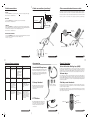
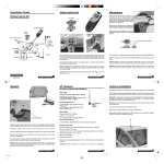
M710 Installation Guide
Transceiver Unit
Product parts list
Microphone
Install the microphone at a distance of no
more than 30 cm (12 inch) away from the
driver’s mouth, ideally on the upper right
hand side of the sun visor and away from
any noise source such as windscreens,
window, fan/air conditioner, car stereo etc.
Unit Holder
Transceiver Unit
Swivel
Mount
Hand-Held
Microphone
Make sure the microphone is at a distance
of at least 1.5m (4.9 ft) from the speaker
and is not directed towards the speaker.
Make sure that the microphone is correctly
positioned. See picture below for
microphone position.
Active GPS Antenna
Maintenance Cable
Slots towards the driver
Privacy
Handest +
Holder
(Optional)
Loudspeaker
Power Cable
and Fuses
Cellular
Antenna
Microphone location
PTT Button
When installing the fixed mobile car phone avoid positioning the transceiver unit
where it may disrupt the proper operation of the vehicle and/or its components, such
as car stereo, air bags, cubbyhole, glove compartment, ashtray, lighter, gear stick,
hand brake, etc...
2A Fuses
12V 24V GND MUTE IGN
Plug the microphone cable into the compatible connection in the control cable.
Important: Make sure that the microphone cable does not come in contact and
does not interfere with the steering wheel and/or the pedals of the vehicle.
Attach the fixed mobile car phone on a stable surface, in a position
that is safe and convenient for the driver to use.
Microphone
Do not thread the microphone cable close to antenna cable, to avoid audio interference.
Special warning:
Do not position the transceiver unit in front of the air bag or where it may impair air
bag performance, as the air bag might inflate in an accident and cause damage.
Attention!
The speaker and microphone (which is fitted on the sun visor above the driver)
should be pointed towards opposite directions to avoid echo.
Verify that the control unit does not face the sun or source of humidity,
such as air conditioner vents.
6889192v48
Motorola Proprietary
Motorola Proprietary
Speaker
2
Specifications
Install the speaker on the side of the central console, ideally alongside the legs of
the passenger sitting beside the driver, as far as possible from the microphone.
Thread the speaker cable under the carpet along the floor of the vehicle.
Plug the speaker cable into the compatible connection in the control cable.
Verify that the cable does not interfere with the proper operation of the vehicle and/or
its components.
Do not conceal the speaker behind any obstacle such as dashboard, carpet or any
other barrier which will result in bad audio quality.
Attention!
The speaker and microphone (which is fitted on the sun visor above the driver)
should be pointed towards opposite directions to avoid echo. speaker slots should
be pointed towards passenger door.
Motorola Proprietary
4
3
Antenna Installation
Antennas
speaker location
Motorola Proprietary
Physical & Environmental Specifications
* GPS Antenna connector: SMA Male
* Radio iDEN Antenna connector: Mini-UHF male
* Cable for the cellular: RG58U, PVC coated /
polyethylene dialectic cable, length 5M / 16Ft
* Cable for the GPS: RG174U, PVC coated /
polyethylene dialectic cable, length 5M / 16Ft
* Operating temperature: -30 ºC / -22 ºF to +85 ºC / +185 ºF
* Heat and UV stabilized
* All parts meet Flammability UL94 V0 grade
* Adhesive pads: Operating temperature: -40 ºC /-40 ºF to +90 ºC / +194 ºF
and bond not effected by moisture
Electrical - GPS
* Impedance: 50Ω
* GPS Module Noise Figure: 2dB max
* Overall Gain: 26dB (GPS Antenna Element Gain 0dBi Min)
* Polarization: Right Hand Circular
* Operating voltage: 3V
* Current (typical): 14mA
* VSWR <2.0:1 @ 1575.4MHz +/- 2MHz
The preferred position for the antenna is on the upper right side of the windshield
Should additicnal antennas be installed in the vehicle, the antennas should be
located at least 30cm apart.
Remember:
In certain car models (such as "Renault Megane" and "Renault Kangoo"), the
anterior windshield has a radiation filter, and therefore it is necessary to paste the
antenna in the side or rear windshield only.
Attention!
Do not thread the antenna cable close to the microphone cable to avoid audio
interference.
Use original antenna plug and clamping tools only.
Test antenna and cable performance using a VSWR meter.
Note:
Avoid proximity to the rear fog heater metal strips. In case the rear heater cannot
be avoided, the metal base area of the antenna should be clear from strips. The
metal base area of the antenna and coupling box should be mounted vertically only.
Electrical - Radio iDEN
* Impedance: 50Ω
* Frequency Band:
* 800 MHz Band: TX 806 - 870 MHz.
* 900 MHz Band: TX 896 - 940 MHz.
* VSWR: Tx<=1.5:1; Rx <=2:1
* Gain: +3dBi @ 820 MHz
* Polarization: Vertical
Attention!
Ensure that antenna is at least 20cm from the driver or passengers
Motorola Proprietary
5
Motorola Proprietary
6
Cable connections (continue)
Cable connections
Data connection/maintenance cable
Entertainment Mute Open Collector connection
Power
The Data connection wire in the mini USB connection in M710 enables using the
fixed mobile car phone as a modem or to synchronize data with external computers.
12V
Connect the RED wire to a positive (+) 12V
Ensure the use of a 2A/250V fuse.
24V pole for steady power supply.
Relay
The data connections also enable authorized technicians to maintain the fixed
mobile car phone for technical service purposes (Software programming).
Common
M710 unit
Ground
Connect the BLACK wire to a negative pole (-) in the vehicle body.
Ensure the use of a 2A/250V fuse.
Command signal
Normally Normally
Open
Close
Ignition
Connect to orange wire
(for Ent. Mute)
Connect the GREEN wire to car IGN voltage and check the appropriate voltage
using voltmeter. This connection switches the phone on when turning the ignition
on and it switches the phone off when turning the ignition off.
Ensure the use of a 2A/250V fuse.
Mini USB
Connection
Entertainment Mute
Connect the ORANGE wire to the car stereo system entertainment mute connection
to mute the stereo system when receiving or dialing a call.
*Ent. Mute is an optional feature.
Control cable
Maintenance cable
2A Fuses
Motorola Proprietary
7
Connections summary
Wire color Function
RED
To supply steady
(+) power source.
Connect to...
12V or 24V
steady power.
Ensure...
The use of a 2A/250V
fuse.
To supply steady
(-) power source.
Vehicle body
That the contact point
is only connected to
the vehicle body.
GREEN
To switch the
phone on when
the car ignition is
turned on, and off
when the car
ignition is turned
off.
IGN voltage
The appropriate
voltage using
voltmeter. Ensure the
use of a 2A/250V
fuse.
To mute the car
stereo system
when receiving or
dialing a call.
Car stereo
system
Entertainment
Mute connection
(optional)
To operate car
lights/horn to
indicate incoming
call.
Car lights/horn
connections
(optional)
8
That the connection
between the Fixed
Mobile Car Phone
and car stereo system
should be done by an
authorized installer
only. sink shoud be up
to 150mA.
That the connection
between the Fixed
Mobile Car Phone
and the car lights/horn
should be done by an
authorized installer
only. sink shoud be up
to 300mA.
Motorola Proprietary
10
Motorola Proprietary
9
Special functions
Voice Activation Dialing key (VAD)
Hand-Held Microphone
BLACK
WHITE
Motorola Proprietary
Accessories
An additional fuse
is supplied that
must be
connected to the
positive (+) pole.
ORANGE
+12V 24V GND MUTE IGN
The VAD is the blue illuminated key on the top side of the main control unit. This
special button, designed as a mouse key is a multiple operations button which
enables the user to voice activate Name dialing, notice incoming calls, record voice
memos and calls and end or receive phone calls by clicking on the button once.
Mount the Hand-Held Microphone in the vehicle
where it will not disrupt the proper operation of
the car and / or its components. Plug the HandHeld Microphone into the hand-held microphone
socket in the control cable.
Volume keys
The volume keys, located on the left hand side of the main control unit enable the
users to adjust audio volume during a call and to adjust the ringer volume during
stand by. While installing the phone in the vehicle don’t place the main control unit
close to the car dashboard or to any other component that might interrupt with the
volume keys operation.
Soft keys and shortcuts
Privacy Handset
Mount the privacy handset using the
plastic base and connect the handset
jack to the socket at the end of the
control cable.
Handset Handset
base base mount
The two soft keys located on the lower part of the phone display enable users to
customize their phone and set useful menus for their convenience and intuitive
location on their phone display.
The navigation key enables the users to launch pre-defined menus in a very quick
and intuitive way instead of entering the phone menus. The navigation key setup
may vary from model to model.
Smart key
PTT Button
Mount the PTT Button in the vehicle where
it will not disrupt the proper operation of
the car and / or its components. Plug the
PTT cable into the PTT socket in the
control cable.
Volume keys
Soft keys
Navigation key
Motorola Proprietary
11
Motorola Proprietary
12