1
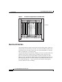
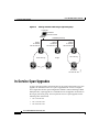
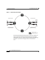
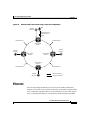
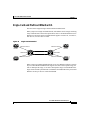
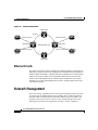
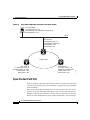
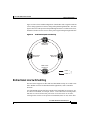
Cisco ONS 15454 Product Overview
Introduction
The Cisco ONS 15454 provides efficient bandwidth delivery and management in
fiber-optic transport networks. It is a flexible, SONET add/drop multiplexer that
offers service aggregation and high-bandwidth transport of voice and data traffic
on a single platform. The ONS 15454 allows users to easily manage services and
quickly increase capacity without disrupting service.
Figure 1
Cisco ONS 15454
Cisco ONS 15454 Product Overview, R3.3
May 2002
1
Cisco ONS 15454 Product Overview
Card Slots and Types
The ONS 15454 is a NEBS-compliant shelf assembly that contains 17 card
(module) slots, a backplane interface, a fan tray, a front panel with an LCD, and
alarm indicators. The ONS 15454 carries traditional time-division multiplexing
(TDM) and high-speed data traffic—a variety of card configurations offer
incremental bandwidth increases as needed and support EC-1, DS-1, DS-3, OC-3,
OC-12, OC-48, OC-192, and 10/100/1000 Ethernet and Gigabit Ethernet speeds.
Workstations can connect to the ONS 15454 using direct, network (LAN and
WAN), or DCC connections. The ONS 15454 supports TL1 and Cisco Transport
Controller (CTC). CTC, the ONS 15454 software interface, provides easy card,
node, and network-level provisioning and troubleshooting. The ONS 15454
deploys a variety of network configurations, including point-to-point systems or
linear add-drop multiplexers (ADMs), unidirectional path switched rings
(UPSRs), two-fiber and four-fiber bidirectional line switched rings (BLSRs),
subtending rings, and path-protected mesh networks (PPMNs). The ONS 15454
can be combined with the Cisco ONS 15327 in several network configurations.
Card Slots and Types
The ONS 15454 has 17 card slots numbered 1–17. All slots are card-ready—when
you plug in a card it automatically boots up and becomes ready for service. The
cards offer bandwidth in modular increments, making it efficient to deploy the
system in low-density applications and add bandwidth as needed. The ONS 15454
houses five types of cards: Common Control, Alarm Interface Controller (AIC),
Electrical, Optical, and Ethernet. The common control cards include the TCC+
and the cross-connect cards (XC, XCVT, and XC10G).
Cisco ONS 15454 Product Overview, R3.3
2
May 2002
Cisco ONS 15454 Product Overview
Card Slots and Types
TCC+ Card
The TCC+ houses the central intelligence of the ONS 15454, including the ONS
15454 OAM&P software interface (CTC).
Figure 2
TCC+ card faceplate
TCC+
FAIL
ACT/STBY
CRIT
MAJ
MIN
REM
SYNC
ACO
ACO
CRAFT
33678 12931
32123
LAN
As the main processing center of the ONS 15454, the TCC+ combines timing,
control, and switching functions:
•
System initialization
•
Provisioning
•
Alarm reporting
•
Maintenance
•
Diagnostics
Cisco ONS 15454 Product Overview, R3.3
May 2002
3
Cisco ONS 15454 Product Overview
Card Slots and Types
•
IP address detection and resolution
•
Timing
•
SONET data communications channel (DCC) termination
•
System fault detection
The CRIT, MAJ, MIN, and REM alarm LEDs on the TCC+ faceplate indicate
whether a Critical, Major, Minor, or Remote alarm is present anywhere on the
ONS 15454 or on a remote node in the network.
In-Service Software Upgrade
The node name, configuration database, IP address, and system software (CTC)
are stored in the TCC+ card’s non-volatile memory, which allows quick recovery
if power or card failures occur. You can upgrade system software without
affecting traffic on the ONS 15454 if dual TCC+ cards are used. The upgrade
takes place first on the standby TCC+ card. The system verifies that the upgrade
is successful and switches from the active TCC+ card running the older release to
the upgraded standby TCC+ card running the newer release. After the switch, the
second TCC+ card undergoes the upgrade. The TCC+ then loads new software to
each of the installed line (traffic) cards.
Database Revert
The increased memory of the TCC+ allows it to store and revert to the previous
configuration database. After a software upgrade, the TCC+ copies the current
working database and saves it in a reserved location in the TCC+ flash memory. If you
later need to revert to the original working software load, the saved database will
activate automatically when you initiate the revert process. There is no need to restore
the database manually.
XC, XCVT, and XC10G Cards
The cross-connect card is the central switching element in the ONS 15454. The
ONS 15454 offers three cross-connect cards: the XC, XCVT, and XC10G. You
provision cross-connect (circuit) information using CTC or TL1; the TCC+ then
establishes the proper internal cross-connect information and relays the setup
information to the cross-connect card.
Cisco ONS 15454 Product Overview, R3.3
4
May 2002
Cisco ONS 15454 Product Overview
Card Slots and Types
Note
For protection purposes, Cisco recommends duplex operation.
Duplex cross-connect cards must be the same type (e.g. two XCs,
two XCVTs, or two XC10Gs).
XC Card
The XC card establishes connections and performs time division switching (TDS) at
the STS-1 level between ONS 15454 traffic cards.
The switch matrix on the XC card consists of 144 STS-1 bidirectional ports. Network
operators can concentrate or groom low-speed traffic from line (traffic) cards onto
high-speed transport spans and to drop low-speed traffic from transport spans onto
line cards.
XCVT Card
The XCVT card provides the same STS capability as a standard XC card but adds
VT1.5 cross-connect capability.
The switch matrix on the XCVT card consists of 144 STS-1 bidirectional ports
and adds a VT matrix that can manage up to 336 bidirectional VT1.5s. The
VT1.5-level signals can be cross connected, dropped, or rearranged.
XC10G Card
The XC10G card supports STS-192 signal rates. The switch matrix on the XC10G
consists of 576 STS-1 bidirectional ports and its VT matrix can manage up to 336
bidirectional VT1.5s. The XC10G is required to operate the OC-192 card or the
OC-48 any-slot cards.
Cisco ONS 15454 Product Overview, R3.3
May 2002
5
Cisco ONS 15454 Product Overview
Card Slots and Types
Figure 3
XC10G faceplate
XC10G
FAIL
68268
ACT/STBY
AIC Card
The optional Alarm Interface Controller (AIC) card provides user-provisionable
alarm capability and supports local and express orderwire. Nodes without an AIC
card can pass the orderwire through to other nodes in the same topology.
Cisco ONS 15454 Product Overview, R3.3
6
May 2002
Cisco ONS 15454 Product Overview
Card Slots and Types
Figure 4
AIC card faceplate
AIC
FAIL
ACT
INPUT 1
INPUT 2
INPUT 3
INPUT 4
OUTPUT 1
OUTPUT 2
OUTPUT 3
OUTPUT 4
CONTACT
STATUS
RING
CALL
LOCAL OW
RING
CALL
32105
EXPRESS OW
The AIC card provides input/output alarm contacts for user-defined alarms. You can
define up to four external alarms and four external controls using the backplane
wire-wrap field to make the physical connections.
Electrical Cards
Slots 1–6 and 12–17 host any electrical card. Each card has faceplate LEDs
showing active, standby, or alarm status, and you can also obtain the status of all
electrical card ports using the LCD screen on the ONS 15454 fan-tray assembly.
Electrical cards (EC-1, DS-1, DS-3, DS3E, and DS3XM) require electrical interface
assemblies (EIAs) to provide the cable connection points for the shelf assembly. In
most cases, EIAs are ordered with the ONS 15454 and come pre-installed on the
backplane. BNC, High-Density BNC, AMP Champ, and SMB are the four types of
EIAs that work with the ONS 15454.
Cisco ONS 15454 Product Overview, R3.3
May 2002
7
Cisco ONS 15454 Product Overview
Card Slots and Types
Note
Optical cards and Ethernet cards have faceplate rather than backplane
connections. E1000-2, E1000-2-G, and G1000-4 (Ethernet) cards
require gigabit interface converters (GBICs) that plug into the card
faceplate.
EC1-12 Card
The EC1-12 card provides 12 Telcordia-compliant, GR-253 STS-1 ports per card.
Each port operates at 51.840 Mbps over a single 75 ohm 728A or equivalent coaxial
span.
The EC1-12 terminates the twelve selected working STS-1 signals from the
backplane. The EC1-12 maps each of the twelve received EC1 signals into 12
STS-1s with visibility into the SONET path overhead.
DS1-14 and DS1N-14 Cards
The DS1-14 card provides 14 Telcordia-compliant, GR-499 DS-1 ports. Each port
operates at 1.544 Mbps over a 100 ohm twisted pair copper cable. The DS1-14 card
can function as a working or protect card in 1:1 protection schemes and as a working
card in 1:N protection schemes. The DS1N-14 card is identical to the DS1-14 and can
also operate as a protect card in a 1:N protection group.
The traffic from an entire DS1-14 card can be grouped and mapped to a single STS-1.
Individual DS-1 ports can be mapped to a VT1.5.
DS3-12 and DS3N-12 Cards
The DS3-12 card provides 12 Telcordia-compliant, GR-499 DS-3 ports per card. Each
port operates at 44.736 Mbps over a single 75 ohm 728A or equivalent coaxial span.
The DS3-12 card operates as a working or protect card in 1:1 protection schemes and
as a working card in 1:N protection scheme. The DS3N-12 card is identical to the
DS3-12 and operates as a protect card in a 1:N protection group.
Cisco ONS 15454 Product Overview, R3.3
8
May 2002
Cisco ONS 15454 Product Overview
Card Slots and Types
DS3-12E and DS3N-12E Cards
The twelve-port DS3-12E and DS3N-12E cards provide enhanced performance
monitoring functions. By monitoring additional overhead in the DS-3 frame, subtle
network degradations are detected.
Figure 5
DS3-12E card faceplate
DS3
12E
FAIL
ACT
55041
SF
The DS3N-12E can operate as the protect card in a 1:N protection group. The
DS3-12E card can only function as the protect card for one other DS3-12E card. If
Software Release 3.0 or higher is used, the card uses all enhanced performance
monitoring functions. With software prior to Release 3.0, the card operates with the
same functions as the older DS-3 card.
With Software R3.1, R3.2, and R3.3 you can perform an in-service upgrade from the
DS3-12/DS3N-12 card to the DS3-12E/DS3N-12E card to take advantage of
enhanced PM functions without disrupting service.
Cisco ONS 15454 Product Overview, R3.3
May 2002
9
Cisco ONS 15454 Product Overview
Card Slots and Types
DS3XM-6 Card
The DS3XM-6 card, commonly referred to as a transmux card, provides six
Telcordia-compliant, GR-499-CORE M13 multiplexing functions. The DS3XM-6
converts six framed DS-3 network connections to 28x6 or 168 VT1.5s.
Optical Cards
The optical cards, with the exception of the original OC-48s and the OC-192,
reside in Slots 1– 6 and 12 – 17. The OC-48 and OC-192 cards reside in Slots 5,
6, 12, and 13. OC-48 Any Slot cards can reside in the same slots as all other
optical cards. You can provision an optical card as a drop card or span card in a
linear ADM (1+1), UPSR, or BLSR protection scheme.
Each card faceplate has three card-level LED indicators. When illuminated, the red
FAIL LED represents a hardware problem, the amber SF LED represents a signal
failure or condition (for example, a loss of frame or a high bit error rate), and the green
ACT LED indicates that the card is operational.
ONS 15454 optical cards have SC fiber connectors on the card faceplate.
OC3 IR 4 1310 Card
The OC3 IR 4 1310 card provides four intermediate- or short-range,
Telcordia-compliant, GR-253 SONET OC-3 ports. The port operates at 155.52 Mbps
over a single-mode fiber span. Each card supports VT and non-concatenated or
concatenated payloads at the STS-1 or STS-3c signal levels. The OC-3 card provides
port-to-port protection.
OC12 IR 1310 Card
The OC12 IR 1310 card provides one intermediate- or short-range,
Telcordia-compliant, GR-253 SONET OC-12 port. The port operates at 622.08
Mbps over a single-mode fiber span and supports VT and non-concatenated or
concatenated payloads at STS-1, STS-3c, STS-6c, or STS-12c signal levels.
Cisco ONS 15454 Product Overview, R3.3
10
May 2002
Cisco ONS 15454 Product Overview
Card Slots and Types
OC12 LR 1310 Card
The OC12 LR 1310 card provides one long-range, Telcordia-compliant, GR-253
SONET OC-12 port per card. The port operates at 622.08 Mbps over a single-mode
fiber span. The card supports VT and non-concatenated or concatenated payloads at
STS-1, STS-3c, STS-6c, or STS-12c signal levels.
OC12 LR 1550 Card
The OC12 LR 1550 card provides one long-range, Telcordia-compliant, GR-253
SONET OC-12 port per card. The port operates at 622.08 Mbps over a single-mode
fiber span. The card supports VT and non-concatenated or concatenated payloads at
STS-1, STS-3c, STS-6c, or STS-12c signal levels.
OC12 IR/STM4-4 1310 Card
The OC12 IR/STM4-4 1310 card provides four intermediate- or short-range,
Telcordia-compliant, GR-253 SONET/SDH OC-12 ports per card. Each port
operates at 622.08 Mbps over a single-mode fiber span. The card supports VT and
non-concatenated or concatenated payloads at the STS-1, STS-3c, STS-6c, or
STS-12c signal levels.
OC48 IR 1310 Card
The OC48 IR 1310 card provides one intermediate-range, Telcordia-compliant,
GR-253 SONET OC-48 port per card. The port operates at 2.49 Gbps over a
single-mode fiber span. The card supports VT and non-concatenated or concatenated
payloads at STS-1, STS-3c, STS-6c, STS-12c, or STS-48c signal levels.
OC48 IR/STM16 SH AS 1310 Card
The OC48 IR/SMT16 SH AS 1310 card provides the same capability as the OC48
IR 1310 card but can be installed in any traffic slot. The OC48 IR 1310 card is
restricted to slots 5, 6, 12, and 13.
Cisco ONS 15454 Product Overview, R3.3
May 2002
11
Cisco ONS 15454 Product Overview
Card Slots and Types
OC48 LR 1550 Card
The OC48 LR 1550 card provides one long-range, Telcordia-compliant, GR-253
SONET OC-48 port per card. The port operates at 2.49 Gbps over a single-mode fiber
span. The card supports VT and non-concatenated or concatenated payloads at STS-1,
STS-3c, STS-6c, STS-12c, or STS-48c signal levels.
OC48 LR/STM16 LH AS 1550 Card
The OC48 IR/SMT16 SH AS 1550 card provides the same capability as the OC48
LR 1550 card but can be installed in any traffic slot. The OC48 LR 1550 card is
restricted to slots 5, 6, 12, and 13.
OC48 ELR 200 GHz DWDM Cards
Eighteen distinct OC48 ITU 200GHz dense wavelength division multiplexing
(DWDM) cards provide the ONS 15454 DWDM channel plan. Each OC-48 DWDM
card provides one Telcordia-compliant, GR-253 SONET OC-48 port. The port
operates at 2.49 Gbps over a single-mode fiber span. The card supports VT and
concatenated or non-concatenated payloads at STS-1, STS-3c, STS-6c, STS-12c, or
STS-48c signal levels.
Nine of the cards operate in the blue band with spacing of 200 GHz on the ITU
grid. The other nine cards operate in the red band with spacing of 200 GHz on the
ITU grid. These cards are also designed to interoperate with the Cisco ONS 15216
DWDM solution.
OC48 ELR/STM16 EH 100 GHz DWDM Cards
Thirty-seven distinct OC48 ITU 100GHz dense wavelength division multiplexing
(DWDM) cards provide the ONS 15454 DWDM channel plan. Each OC-48
DWDM card has one Telcordia-compliant, GR-253 SONET OC-48/SDH STM-16
ITU-T G.692 and ITU-T G.958 port. The port operates at 2.49 Gbps over a
single-mode fiber span. The card supports VT and concatenated or
non-concatenated payloads at STS-1, STS-3c, STS-6c, STS-12c, or STS-48c
signal levels.
Nineteen of the cards operate in the blue band with spacing of 100 GHz on the
ITU grid. The other eighteen cards operate in the red band with spacing of 100
GHz on the ITU grid.
Cisco ONS 15454 Product Overview, R3.3
12
May 2002
Cisco ONS 15454 Product Overview
Card Slots and Types
OC192 LR/STM64 LH 1550 Card
The OC192 LR/STM64 LH 1550 card provides one long-range, Telcordia-compliant,
GR-253 SONET OC-192 port per card. The port operates at 9.95 Gbps over a
single-mode fiber span. The card supports VT and non-concatenated or concatenated
payloads at STS-1, STS-3c, STS-6c, STS-12c, STS-48c, or STS-192c signal levels.
Figure 6
OC-192 card faceplate
OC192LR
STM64LH
1550
FAIL
ACT/STBY
SF
0
1
TX
1
RX
TX
DANGER - INVISIBLE
LASER RADIATION
MAY BE EMITTED
FROM THE END OF
UNTERMINATED
FIBER CABLE OR
CONNECTOR. DO
NOT STARE INTO
BEAM OR VIEW
DIRECTLY WITH
OPTICAL
INSTRUMENTS.
RX
!
MAX INPUT
POWER LEVEL
- 10dBm
Class 1M (IEC)
61361
Class 1 (CDRH)
Cisco ONS 15454 Product Overview, R3.3
May 2002
13
Cisco ONS 15454 Product Overview
Card Slots and Types
Ethernet Cards
The Ethernet cards eliminate the need for external Ethernet aggregation equipment
and provide efficient transport and co-existence of traditional TDM traffic with
packet-switched data traffic. Multiple Ethernet cards installed in an ONS 15454 can
act as a single switch (EtherSwitch) supporting a variety of SONET port
configurations.
E100T-12/E100T-G Card
The ONS 15454 uses E100T-12/ E100T-G cards for Ethernet (10 Mbps) and Fast
Ethernet (100 Mbps). Each card provides twelve switched, IEEE 802.3-compliant,
10/100 Base-T Ethernet interfaces that can independently detect the speed of an
attached device (auto-sense) and automatically connect at the appropriate speed. The
ports auto-configure to operate at either half or full duplex and can determine whether
to enable or disable flow control. You can also configure Ethernet ports manually.
The E100T-G card operates with the XC, XCVT, and XC10G cross-connect cards.
The E100T-12 operates with the XC or XCVT; it is incompatible with the XC10G.
E1000-2/E1000-2-G Card
The ONS 15454 uses the E1000-2 and E1000-2-G cards for Gigabit Ethernet
(1000 Mbps).They provide two ports of IEEE-compliant, 1000 Mbps interfaces for
high-capacity customer LAN interconnections. Each interface supports full-duplex
operation.
The E1000-2-G card operates with the XC, XCVT, and XC10G cross-connect
cards. The E1000-2 operates with the XC and XCVT; it is incompatible with the
XC10G.
The E1000-2 and E1000-2-G cards use gigabit interface converter (GBIC) modular
receptacles for the optical interfaces. GBICs are hot-swappable input/output devices
that plug into a Gigabit Ethernet port to link the port with the fiber-optic network.
Cisco provides two GBIC models: one for short reach applications and one for
long-reach applications. The short reach model connects to multimode fiber and the
long reach model requires single-mode fiber.
Cisco ONS 15454 Product Overview, R3.3
14
May 2002
Cisco ONS 15454 Product Overview
Card Protection
Gigabit interface converter
11825
Figure 7
Receiver
Transmitter
G1000-4 Card
Like the E1000-2 and E1000-2-G cards, the G1000-4 card provides
IEEE-compliant, 1000 Mbps ports for full-duplex operation and requires a GBIC
as its optical interface. However, the G1000-4 has four ports rather than two and
requires the XC10G as its cross-connect card. The additional ports give the ONS
15454 a practical limit of 40 Gigabit Ethernet ports per node. The G1000-4
operates on layer 1 and is used only for point-to-point circuits. OC-48 is the
maximum bandwidth on each G1000-4 card.
Card Protection
The ONS 15454 provides 1:1 and 1:N electrical protection and 1+1 optical
protection methods. This section describes the protection options and explains
protection switching in the ONS 15454. For a description of Ethernet protection,
see the “Spanning Tree Protocol” section on page 32.
Cisco ONS 15454 Product Overview, R3.3
May 2002
15
Cisco ONS 15454 Product Overview
Card Protection
Figure 8
1:1 electrical card protection in the ONS 15454
33384
Protect
Working
Protect
Working
Working
Protect
TCC+
XC10G
XC10G
AIC (Optional)
Working
TCC+
Protect
Working
Protect
Working
Protect
1:1 Protection
Electrical Protection
1:N protection allows a single card to protect several working cards. A DS1N-14
card provides protection for up to five DS1-14 cards, and a DS3N-12/DS3N-12E
card protects up to five DS3-12/DS3-12E cards. The standard DS1-14 card and
DS3-12 card provide 1:1 protection only.
1:N protection operates only at the DS-1 and DS-3 levels. The 1:N protect cards must
match the levels of their working cards. For example, a DS1N-14 protects only
DS1-14 or other DS1N-14 cards, and a DS3N-12 protects only DS3-12 or other
DS3N-12 cards. 1:N cards have added circuitry to act as the protection card in a 1:N
protection group. Otherwise, the card is identical to the standard card and can serve
as a normal working card. 1:1 and 1:N protection in the ONS 15454 supports
revertive and non-revertive switching.
Cisco ONS 15454 Product Overview, R3.3
16
May 2002
Cisco ONS 15454 Product Overview
Cisco Transport Controller
Optical Protection
The ONS 15454 supports 1+1 protection to create redundancy for optical cards
and spans. With 1+1 protection, one optical port can protect another optical port;
therefore, in any two high-speed slots a single working card and a single dedicated
protect card of the same type (for example, two OC-48 cards) can be paired for
protection. If the working port fails, the protect port takes over. 1+1 span
protection can be either revertive or non-revertive.
Because the OC-3 card is a multiport card, port-to-port protection is available.
The ports on the protect card support the corresponding ports on the working card.
Protection Switching
The ONS 15454 supports revertive and non-revertive, unidirectional or
bidirectional switching for optical signals. 1:N electrical protection is always
revertive and bidirectional; 1:1 electrical protection is also bidirectional but
provides the revertive or non-revertive option.
When a failure occurs and automatic protection switching (APS) switches the
signal from the working card to the protect card, non-revertive switching does not
revert the traffic to the working card automatically when the working card reverts
to active status. When a failure is cleared, revertive switching automatically
switches the signal back to the working card after the provisionable revertive time
period has elapsed.
When a failure occurs to a signal that is provisioned as bidirectional, both the
transmit and receive signals are switched away from the point of failure (the port
or card). A unidirectional signal switches only the failure direction, either
transmit or receive.
Cisco Transport Controller
Cisco Transport Controller (CTC) is a software program that is automatically
downloaded from the TCC+ card to your workstation when you connect to the
ONS 15454. CTC gives you control of Operation, Administration, Maintenance,
and Provisioning (OAM&P) activities for the ONS 15454.
Cisco ONS 15454 Product Overview, R3.3
May 2002
17
Cisco ONS 15454 Product Overview
Cisco Transport Controller
Graphical User Interface
The CTC graphical user interface (GUI), also called the CTC window, provides
three primary views, or modes, that include:
•
Network view—Provides information about the ONS 15454 network and
displays a graphic of the United States with ONS 15454 nodes represented by
colored icons. The color of the icon represents the node status, and you can
perform network management tasks or display any node. See the
“Customized Network View” section on page 20 for information about
changing the default network map and adding domains.
•
Node view—Provides information about the node and displays a graphic of
the ONS 15454 shelf. This is the default view displayed each time you log
into CTC, and you perform node management tasks in this view. The cards
are color-coded to show the status of the physical cards and ports.
•
Card view—Provides information about individual ONS 15454 cards and
displays a graphic of the selected card. You perform card and port-specific
maintenance tasks in this view. The information that displays and the tasks
you can perform depend on the card.
Figure 9
CTC GUI (window) in node view
Menu bar
Tool bar
Status area
Top
pane
Graphic area
Tabs
Bottom
pane
61017
Subtabs
Cisco ONS 15454 Product Overview, R3.3
18
May 2002
Cisco ONS 15454 Product Overview
Cisco Transport Controller
The CTC GUI displays tabs and subtabs. From the tabs you can perform all the
OAM&P tasks, such as provisioning cards, circuits, and rings; creating protection
groups; setting timing parameters; viewing and clearing alarms; provisioning DCCs;
backing up and restoring the database; and troubleshooting, including creating
diagnostic files and performing loopbacks.
Proxy Server Features
The proxy server feature set allows CTC to access ONS 15454s while restricting
unauthorized IP connectivity. It can also be used to reduce the amount of network
provisioning required for external routers and CTC workstations.
The proxy server feature set consists of the following:
•
ARP sniffing—Also known as automatic host detection, this feature allows a
CTC workstation on a different subnet than the target ONS 15454 to directly
connect and launch CTC.
•
Proxy server—When this feature is enabled, one ONS 15454 will act like a
as a network proxy for other DCC-connected nodes that do not have direct IP
connectivity.
•
Firewall—When this feature is enabled, certain IP communications are
restricted between an ONS 15454’s SDCC channels and the TCC+ card’s
Ethernet port. This prevents CTC workstations from using the ONS 15454’s
SDCC communication path to access other workstations on the data
communications network.
Password Security
CTC employs password complexity rules to enhance login security, including the
following rules:
•
The user ID and password cannot be identical, nor can the password contain
the user ID sequence of characters.
•
Newly created passwords must comply with Telcordia GR-815, which
requires that passwords be at least 6 characters long, and contain at least one
alphabetic character, one numeric character, and one special character (+, #,
or %). CTC will display a warning for previously created passwords that do
not meet these requirements but permits the user to continue.
Cisco ONS 15454 Product Overview, R3.3
May 2002
19
Cisco ONS 15454 Product Overview
Cisco Transport Controller
Customized Network View
With CTC you can install a custom map for the network view. The map can be any
map you choose, such as a regional map (Figure 10) or even a street map. You can
drag and drop nodes to move their location on the map.
To further customize the CTC network view, you can create domains that manage the
display of multiple nodes on the network map. Domains appear as a cloud on the
network view. A single domain can have any number of nodes, and you can drill into
the domain and display or log into any node.
Customized network topology map
61872
Figure 10
Cisco ONS 15454 Product Overview, R3.3
20
May 2002
Cisco ONS 15454 Product Overview
Cisco Transport Controller
Circuit Provisioning and Management
CTC enables automated circuit provisioning across ONS 15454 networks and
between ONS 15454s and ONS 15327s, including STS and VT1.5 circuits and VT
tunnels, as well as multiple drop and monitor circuits. From the CTC GUI, select a
source and destination ONS 15454 or ONS 15327 to create an end-to-end circuit.
CTC automatically calculates a circuit path between the source and destination.
You select the circuit type, circuit size, bidirectional or unidirectional status, and
path-protection or protected drops restrictions. You can also route circuits
manually, for example, to force traffic onto a particular path. See the “Ethernet
Circuits” section on page 34 for a description of Ethernet circuits.
Figure 11
Creating circuits with the CTC Circuit Creation dialog box
Auto Range
CTC provides an auto-range feature that automatically creates sequential circuits,
which prevents you from needing to individually build circuits of the same type.
Specify the number of circuits you need, create one circuit, and CTC
automatically creates additional sequential circuits.
Cisco ONS 15454 Product Overview, R3.3
May 2002
21
Cisco ONS 15454 Product Overview
Cisco Transport Controller
Detailed Circuit Map
The detailed circuit map provides an end-to-end view of circuits rather than
simply nodes and their spans. Specifically the circuit map shows ports, drops,
spans, and selectors for UPSR circuits.
Figure 12
Detailed circuit map
Performance Monitoring
CTC displays section, line, and path performance monitoring for optical,
electrical, and Ethernet statistics, as defined in GR-253-CORE and
GR-820-CORE. For each statistic, you can display 31 previous 15-minute
intervals and the current 15-minute interval, as well as the previous 24-hour and
current 24-hour interval.
Cisco ONS 15454 Product Overview, R3.3
22
May 2002
Cisco ONS 15454 Product Overview
Login Options
The Cisco ONS 15454 Reference Guide, Release 3.3, provides detailed
performance monitoring information for each card.
Login Options
The ONS 15454 offers network management flexibility. You can choose to see the
login node, nodes with DCC-connectivity to the login node, and nodes that are not
DCC-connected to the node.
DCC Connectivity
The ONS 15454 uses SONET data communication channels (SDCCs) for CTC
connectivity, automated circuit provisioning, and alarm reporting from remote
nodes. Using a node’s SDCC, CTC automatically finds and recognizes other ONS
15454s. However, during login you can choose to exclude DCC-connected nodes
from auto-discovery, which speeds up login time and reduces clutter on the
network map.
Login Node Groups
When you log into an ONS 15454 node, only ONS 15454s with DCC connectivity to
the node are autodiscovered and displayed in network view. However, you can create
a login node group to view and manage ONS 15454s that have an IP connection but
no DCC-connectivity to the login node.
For example, in Figure 13, if you logged into Node 1 you would see Node 2 and Node
3 because they have DCC connectivity to Node 1. You would not see Nodes 4, 5, and
6 because DCC connections do not exist. To view all six nodes at once, create a login
node group with the IP addresses of Nodes 1, 4, and 5. Those nodes, and all nodes
optically connected to them, will display when you log into any node in the group.
Cisco ONS 15454 Product Overview, R3.3
May 2002
23
Cisco ONS 15454 Product Overview
In-Service Span Upgrades
Figure 13
Viewing non-DCC nodes using a login node group
Laptop PC
IP Address
192.168.106.100
LAN/WAN (Ethernet)
Node 1
IP Address
192.168.106.143
Node 4
IP Address
192.168.105.119
Node 5
IP Address
192.168.104.109
Two node ring
Node 2
Single
Node 3
Node 6
IP Address
192.168.103.199
55029
Three node ring
In-Service Span Upgrades
A span is the optical-fiber connection between two ONS 15454 nodes. In a span
upgrade, the transmission rate of a span is upgraded from a lower to a higher
OC-N signal but all other span configuration attributes remain unchanged. With
multiple nodes, a span upgrade is a coordinated series of upgrades on all nodes in
the ring or protection group. You can perform in-service span upgrades for the
following ONS 15454 cards:
•
OC-12 to OC-48
•
OC-12 to OC-192
•
OC-48 to OC-192
Cisco ONS 15454 Product Overview, R3.3
24
May 2002
Cisco ONS 15454 Product Overview
TL1
To perform a span upgrade, the higher-rate optical card must replace the
lower-rate card in the same slot. The protection configuration of the original
lower-rate optical card (two-fiber BLSR, four-fiber BLSR, UPSR, and 1+1) is
retained for the higher-rate optical card. The Span Upgrade Wizard automates all
steps in the manual span upgrade procedure for all protection configurations.
TL1
The ONS 15454 supports up to twenty concurrent TL1 sessions that provide the
full range of TL1 commands for provisioning and managing ONS 15454 nodes.
The Cisco ONS 15454 and Cisco ONS 15327 TL1 Command Guide, Release 3.3
provides a complete list of commands, including specific sections devoted to ring
provisioning and alarms and errors.
TL1 Communication
You can enable TL1 in three ways:
•
Launch CTC and open a TL1 session to enter TL1 commands.
•
Use port number 2361, 3082, or 3083 to access TL1 commands using a telnet
session.
•
Use the backplane craft interface or the nine-pin RS-232 port on the TCC+ to
open a VT100 emulation window and enter TL1 commands.
TL1 Gateway and TL1 Test Access
TL1 Gateway enables you to issue TL1 commands to multiple nodes using a single
connection. This means you can now provision other nodes in the network from the
workstation where you are logged in.
TL1 Test Access enables you to monitor and test circuits. Commands to connect,
disconnect, and change the test access (TACC) connections are available.
Cisco ONS 15454 Product Overview, R3.3
May 2002
25
Cisco ONS 15454 Product Overview
Alarm Collection and Display
Alarm Collection and Display
The ONS 15454 has several methods to alert you to possible problems with the
node.The ONS 15454 faceplate has LEDs that alert you to critical, major, minor,
or remote alarms on the node. The LCD provides this information but on a port
and card level also. CTC displays alarms and events on a card or node level for all
nodes in the network. You can also use TL1 to view and troubleshoot the same
alarm messages that appear in CTC.
Front Panel LEDs
The Critical, Major and Minor alarm LEDs on the fan tray front panel indicate
whether a critical, major, or minor alarm is present anywhere on the ONS 15454
assembly. These LEDs are viewable through the front door so that you can quickly
determine if any alarms are present on the assembly. These LEDs are independent
of the Slot, Status, and Port indicators on the LCD.
LCD Alarm Indicators
The ONS 15454 LCD screen provides slot and port-level information for all ONS
15454 card slots, including the number of Critical, Major, and Minor alarms.
Slot
Using the LCD
Status
Port
06/29/01
24˚C
03.00-001A-00
FAN FAIL CRIT
MAJ
MIN
34192
Figure 14
Cisco ONS 15454 Product Overview, R3.3
26
May 2002
Cisco ONS 15454 Product Overview
Alarm Collection and Display
CTC Display
Alarms are displayed in one of five background colors to quickly communicate the
alarm severity. You can control the display of current and cleared alarms generated on
the node. The alarm and event screens include date, time, severity, reporting node,
reporting object, service-affecting status, and a description.
Figure 15
Viewing alarms for the current session
CTC displays historical alarm data and shows events (non-alarmed occurrences)
such as performance monitoring threshold crossings or protection switching
events. CTC presents two alarm history views:
•
A Session subtab presents alarms and events for the current CTC session.
When you log off, the alarm list generated during the CTC session disappears.
•
A Node subtab shows the alarms and events that occurred at the node since
the CTC software installation. The ONS 15454 can store up to 256 critical
alarms, 256 major alarms, 256 minor alarms, and 256 events. When the limit
is reached, the ONS 15454 discards the oldest alarms and events.
Cisco ONS 15454 Product Overview, R3.3
May 2002
27
Cisco ONS 15454 Product Overview
Alarm Collection and Display
Alarm Profiles
The ONS 15454 includes an alarm profile feature. This allows you to change the
default alarm severities (for example, change an alarm severity from minor to
major) and apply the new severities at the card, port, or node level.
Figure 16
Creating alarm profiles with the Alarm Profiles tab
Every alarm has a default severity. To create a new profile, clone the default in CTC,
rename it, and choose the severity settings for the new profile.
Cisco ONS 15454 Product Overview, R3.3
28
May 2002
Cisco ONS 15454 Product Overview
Alarm Collection and Display
Alarm Suppression
From the card view you can suppress alarms on specific ports. From the node
view, you can suppress alarms on specific cards or the entire node.
If alarms are suppressed, they do not appear on the CTC Alarm screen. On the
History screen a message states that the alarms are suppressed, and the Conditions
tab shows alarm suppression conditions. The node sends out autonomous
messages to clear any raised alarms. When alarm suppression is turned off, the
node sends out autonomous messages to raise any suppressed alarms.
Alarm Cutoff
Visual and audible (user-defined) alarms are typically wired to trigger an alarm
light or sound at a central alarm collection point when the corresponding contacts
are closed. The alarm cutoff (ACO) function stops (turns off) the transmission of
the alarm signal to the alarm collection point. To activate the ACO function, press
the ACO button on the AIC card faceplate. The ACO button clears all audible alarm
indications. The alarm is still active in CTC and needs to be cleared.
Customer-Defined External Alarms and Controls
The AIC card allows you to provision four external alarms and four external
controls. Use external alarms for open doors, temperature sensors, flood sensors, and
other environmental conditions. Use external controls to drive visual or audible
devices such as bells and lights. The alarm-triggering conditions for the external
controls can be user-defined external input alarms, remote alarms, or severity-based
alarms (for example, alarms that trigger when any Major alarm happens).
Figure 17 shows a diagram of the input and output process for external alarms and
controls.
Cisco ONS 15454 Product Overview, R3.3
May 2002
29
Cisco ONS 15454 Product Overview
Alarm Collection and Display
External alarm input and output
External control
Bell
External alarms
Relay
Relay
Relay
Relay
Light
Smoke
detector
Heat
sensor
CTC alarm turns on
an external device
External device
generates CTC alarm
= External alarm
= External control
38566
Figure 17
Provisioning external alarms and controls provides a “virtual wires” option that you
can use to route alarms and controls from different nodes to one or more alarm
collection centers. For example, in Figure 18, smoke detectors are provisioned as
external alarms at Nodes 1, 2, 3, and 4. The alarms are assigned to Virtual Wire 1, and
Virtual Wire 1 is provisioned as the trigger (control) for an external bell at
Node 1.
Cisco ONS 15454 Product Overview, R3.3
30
May 2002
Cisco ONS 15454 Product Overview
Ethernet
Figure 18
External alarms and controls using a virtual wire configuration
Bell
Smoke
detector
Virtual Wire #1 is
external control
trigger
Virtual Wire #1
Virtual Wire #1
ONS 15454
Node 1
Smoke
detector
Smoke
detector
ONS 15454
Node 4
ONS 15454
Node 2
ONS 15454
Node 3
Virtual Wire #1
Smoke
detector
= External alarm
= External control
44743
Virtual Wire #1
Ethernet
The ONS 15454 integrates Ethernet access into the same SONET platform that
transports voice traffic. Service providers use Ethernet over SONET to augment TDM
services while delivering data traffic over existing facilities. The ONS 15454 supports
layer 2 switching and the ability to classify Ethernet traffic as defined in the IEEE
Cisco ONS 15454 Product Overview, R3.3
May 2002
31
Cisco ONS 15454 Product Overview
Ethernet
802.1 Q-tag standard. You can switch tagged traffic onto separate SONET STS
channels to engineer bandwidth by traffic class. The ONS 15454 can also concentrate
Ethernet ports into one or more STS-N circuits to use bandwidth more efficiently.
Priority Queuing
Networks without priority queuing handle all packets on a first-in-first-out basis.
Priority queuing, which is supported by the ONS 15454, reduces the impact of
network congestion by mapping Ethernet traffic to different priority levels. The
ONS 15454 takes the eight priorities specified in IEEE 802.1Q and maps them to
two queues. Q-tags carry priority queuing information through the network.
VLAN Service
The ONS 15454 works with Ethernet devices that do and do not support IEEE
802.1Q tagging. The ONS 15454 supports virtual LANs that provide private network
service across a SONET backbone. You can define specific Ethernet ports and
SONET STS channels as a VLAN group. VLAN groups isolate subscriber traffic
from users outside the VLAN group and keep “outside” traffic from “leaking” into the
virtual private network (VPN). Each IEEE 802.1Q VLAN represents a different
logical network.
Spanning Tree Protocol
The ONS 15454 uses the IEEE 802.1D standard to provide spanning tree protocol
(STP). STP detects and eliminates network loops; the ONS 15454 uses spanning tree
protocol internally and externally. Internally, it detects multiple circuit paths between
any two network ports and blocks ports until only one path exists. The single path
eliminates possible bridge loops.
Externally, you can enable spanning tree at the Ethernet-port level to allow parallel
connections to external networking equipment. Spanning tree will only allow one
connection to be used at any given time. You can disable spanning tree protection on
a circuit-by-circuit basis on unstitched Ethernet cards in a point-to-point
configuration.
Cisco ONS 15454 Product Overview, R3.3
32
May 2002
Cisco ONS 15454 Product Overview
Ethernet
Single-Card and Multicard EtherSwitch
The ONS 15454 supports single-card and multicard EtherSwitch.
When you provision single-card EtherSwitch, each Ethernet card is a single switching
entity within the ONS 15454. This option allows STS-12c of bandwidth between two
Ethernet circuit points. Single-card EtherSwitch supports one STS-12c, two STS-6c,
four STS-3c, or twelve STS-1 circuits.
Figure 19
Single-card EtherSwitch
Ethernet card 1
Ethernet card 2
Router
Router
ONS Node
VLAN A
ONS Node
VLAN B
Router
Ethernet card 4
45132
Ethernet card 3
Router
When you provision multicard EtherSwitch, two or more Ethernet cards act as a single
layer 2 switch. Multicard EtherSwitch supports one STS-6c shared packet ring, two
STS-3c shared packet rings, or six STS-1 shared packet rings. The bandwidth of the
single switch formed by the Ethernet cards matches the bandwidth of the provisioned
Ethernet circuit up to STS-6c worth of bandwidth.
Cisco ONS 15454 Product Overview, R3.3
May 2002
33
Cisco ONS 15454 Product Overview
Network Management
Figure 20
Multicard EtherSwitch
ONS Node
VLAN A
Ethernet card 1
Ethernet card 2
Router
Router
Shared packet ring
Ethernet card 3
ONS Node
Ethernet card 4
Router
45133
ONS Node
Router
ONS Node
Ethernet Circuits
The ONS 15454 has three common methods for configuring Ethernet circuits between
ONS nodes: a point-to-point circuit configuration, a shared packet ring configuration
(Multicard EtherSwitch only), and a hub-and-spoke configuration. Two nodes usually
connect with a point-to-point circuit configuration. More than two nodes usually
connect with a shared packet ring or a hub and spoke configuration. You can also
manually cross connect individual Ethernet circuits to an STS channel on the ONS
15454 optical interface.
Network Management
The ONS 15454 is compatible with several network management protocols, such
as Simple Network Management Protocol (SNMP), Proxy Address Resolution
Protocol (ARP), and Open Shortest Path First (OSPF) protocol. If OSPF is not
available, static routes can also connect to ONS 15454s through routers. DCC
tunneling is provided for interoperability with other vendors’ equipment.
Cisco ONS 15454 Product Overview, R3.3
34
May 2002
Cisco ONS 15454 Product Overview
Network Management
Simple Network Management Protocol
Simple Network Management Protocol (SNMP) is an application-layer Internet
Protocol (IP) that enables network devices to exchange management information.
Network administrators can manage network performance, find and solve network
problems, and plan for network growth. The ONS 15454 supports SNMP Version
1 (SNMPv1) and SNMP Version 2c (SNMPv2c); SNMPv2c offers additional
protocol operations.
The ONS 15454 uses SNMP to communicate segments of the CTC information
model to network management systems, such as HP OpenView Network Node
Manager (NNM) or Open Systems Interconnection (OSI) NetExpert. SNMP conveys
information required for node-level inventory, fault, and performance management of
the ONS 15454 node, and for generic read-only management of DS-1, DS-3, SONET,
and Ethernet.
The ONS 15454 incorporates SNMP Remote Monitoring (RMON) to allow
network operators to monitor the ONS 15454 Ethernet cards. RMON operates
transparently with a network management application, but you can provision
RMON alarm thresholds with CTC.
Proxy ARP
Proxy ARP enables a LAN-connected gateway ONS 15454 to automatically
handle ARP requests for remote non-LAN ONS 15454s connected by a DCC to
the gateway ONS 15454. Proxy ARP requires no manual configuration in CTC.
Proxy ARP has a single LAN-connected ONS 15454 stand in (proxy) for remote ONS
15454s. If a device on the LAN sends an ARP request intended for one of the
DCC-connected ONS 15454s, the gateway ONS 15454 returns its own MAC address
to the LAN device. The LAN device then sends the datagram intended for the remote
ONS 15454 to the MAC address of the proxy ONS 15454. The proxy ONS 15454
forwards this data to the remote 15454 using its own ARP table.
Cisco ONS 15454 Product Overview, R3.3
May 2002
35
Cisco ONS 15454 Product Overview
Network Management
Figure 21
Proxy ARP configuration (all nodes on the same subnet)
CTC Workstation
IP Address 192.168.1.100
Subnet Mark at CTC Workstation 255.255.255.0
Default Gateway = N/A
LAN A
ONS 15454 #1
IP Address 192.168.1.10
Subnet Mask 255.255.255.0
Default Router = N/A
Static Routes = N/A
ONS 15454 #2
IP Address 192.168.1.20
Subnet Mask 255.255.255.0
Default Router = N/A
Static Routes = N/A
ONS 15454 #3
IP Address 192.168.1.30
Subnet Mask 255.255.255.0
Default Router = N/A
Static Routes = N/A
33159
SONET RING
Open Shortest Path First
If ONS 15454s are connected to Open Shortest Path First (OSPF) networks, ONS
15454 network information can be automatically communicated across multiple
LANs and WANs.
OSPF is a link state Internet routing protocol. Link state protocols use a “hello
protocol” to monitor their links with adjacent routers and test their links to their
neighbors. Link state protocols advertise their directly-connected networks and
their active links. Each link state router captures the link state “advertisements”
Cisco ONS 15454 Product Overview, R3.3
36
May 2002
Cisco ONS 15454 Product Overview
Network Management
and puts them together to create a topology of the entire network or area. From
this database, the router calculates a routing table by constructing a shortest path
tree. Routes are continuously recalculated to capture ongoing topology changes.
You can enable OSPF on the ONS 15454s so that the ONS 15454 topology is sent
to OSPF routers on a LAN. Advertising the ONS 15454 network topology to LAN
routers eliminates the need to manually provision static routes for ONS 15454
subnetworks.
Static Route Provisioning
The ONS 15454 uses CTC to provision static network routes. Static routes allow
workstations to connect to ONS 15454s through routers. Static routes also make
it possible to have multiple CTC sessions, with different destination IP addresses,
on a network of ONS 15454s that all lie on the same subnet. For example, a
network operations center (NOC) can remotely monitor an ONS 15454 through
CTC concurrently with an on-site employee logged into a network ONS 15454
with a separate CTC session. If OSPF is connected and running, static routes are
unnecessary.
DCC Tunneling
You can tunnel third-party SONET equipment DCCs across ONS 15454 networks. A
DCC tunnel is a series of connection points that map a third-party equipment DCC to
ONS 15454 DCCs. A DCC tunnel end point is defined by the slot, port, and DCC type.
To create a DCC tunnel, you connect the tunnel end points from one ONS 15454
optical port to another. DCC traffic is forwarded transparently, byte-for-byte, across
the ONS 15454 network.
Cisco ONS 15454 Product Overview, R3.3
May 2002
37
Cisco ONS 15454 Product Overview
Network Configuration
Network Configuration
The ONS 15454 supports unidirectional path switched rings (UPSRs),
bidirectional line switched rings (BLSRs), subtending rings, linear add-drop
multiplexer (ADM) supporting 1+1 protection, and mixed configurations. You can
also create path-protected mesh networks (PPMNs).
Unidirectional Path Switched Ring
The default protection scheme for an ONS 15454 is the UPSR. A UPSR is a
closed-loop, two-fiber transport architecture that survives cable cuts and
equipment failure because it provides duplicate fiber paths for each service.
Nodes in the ring are connected using a single pair of optical fibers. Working
traffic flows in one direction on the ring and the second fiber provides a protection
path flowing in the opposite direction. If a problem occurs in the working traffic
path, the receiving node switches to the path coming from the opposite direction.
Services can originate and terminate on the same UPSR or can be passed to an
adjacent access or interoffice ring for transport to the service-terminating
location. Because each traffic path is transported around the entire ring, UPSRs
are best suited for networks where traffic concentrates in one or two locations and
is not widely distributed.
Cisco ONS 15454 Product Overview, R3.3
38
May 2002
Cisco ONS 15454 Product Overview
Network Configuration
Figure 22 shows a basic UPSR configuration. If Node ID 0 sends a signal to Node ID
2, the working signal travels on the working traffic path through Node ID 1. The same
signal is also sent on the protect traffic path through Node ID 3. If a fiber break occurs,
Node ID 2 switches its active receiver to the protect signal coming through Node ID 3.
Figure 22
Unidirectional path switched ring
ONS 15454
Node ID 0
ONS 15454
Node ID 3
ONS 15454
Node ID 1
= Fiber 1
= Fiber 2
32148
ONS 15454
Node ID 2
Bidirectional Line Switched Ring
The ONS 15454 supports two-fiber and four-fiber BLSRs with up to 16 ONS 15454
nodes. BLSRs work well for distributed traffic applications, such as interoffice
networks.
Two-fiber BLSRs allocate half the available fiber bandwidth for protection. In a
two-fiber OC-48 BLSR, for example, STSs 1–24 are allocated to working traffic,
and STSs 25–48 are allocated for protection. If a break occurs on one fiber,
working traffic switches to the protection bandwidth (STSs 25–48) on the other
Cisco ONS 15454 Product Overview, R3.3
May 2002
39
Cisco ONS 15454 Product Overview
Network Configuration
fiber. Working traffic travels in one direction on STSs 1–24 on one fiber, and on
STSs 1–24 in the opposite direction on the second fiber. You can create OC-12,
OC-48, and OC-192 two-fiber BLSRs.
Figure 23
Four-fiber bidirectional line switched ring
Node 0
Span 4
Span 1
Span 5
Span 8
OC-48 Ring
Node 3
Span 6
Node 1
Span 7
Span 2
= Working fibers
Node 2
= Protect fibers
61932
Span 3
Four-fiber BLSRs double the bandwidth of two-fiber BLSRs by dedicating a
second optical card for protection rather than reserving half of the active card for
protection. If one fiber is cut, the ring does not switch because the other fiber
carries the traffic for the broken span. A ring switch occurs if both the working
and protect fibers fail. You can create OC-48 and OC-192 four-fiber BLSR.
Cisco ONS 15454 Product Overview, R3.3
40
May 2002
Cisco ONS 15454 Product Overview
Network Configuration
Subtending Rings
UPSRs and BLSRs can be subtended from one another using one shared node; the
node can terminate and groom any one of the following ring combinations:
•
5 UPSRs, or
•
4 UPSRs and 1 BLSR, or
•
3 UPSRs and 2 BLSRs
Subtending rings from an ONS 15454 reduces the number of nodes and cards
required, and reduces external shelf-to-shelf cabling. Figure 24 shows an ONS
15454 with multiple subtending rings.
Figure 24
An ONS 15454 with multiple subtending rings
Path
Protected
Nodes
BLSR
55302
BLSR
Cisco ONS 15454 Product Overview, R3.3
May 2002
41
Cisco ONS 15454 Product Overview
Network Configuration
Figure 25 shows a UPSR subtending from a BLSR. In this example, Node 3 is the
only node serving both the BLSR and UPSR. Optical cards in Slots 5 and 12 serve
the BLSR, and optical cards in Slots 6 and 13 serve the UPSR.
Figure 25
UPSR subtending from a BLSR
Path
Protected
Nodes
BLSR
55302
BLSR
Linear Add/Drop Multiplexer Mode
In ADM configuration, intermediate nodes have direct access to eastbound or
westbound STS channels along a fiber route, and can connect any STS to any
other STS for transport along the network. ADM configurations eliminate the
need for costly “back-to-back” terminal configurations and can be enhanced with
1+1 protection for any or all transport spans in the system. Figure 26 shows an
ADM configuration.
Cisco ONS 15454 Product Overview, R3.3
42
May 2002
Cisco ONS 15454 Product Overview
Network Configuration
Linear ADM configuration
Slot 6 to Slot 6
Slot 12 to Slot 12
Slot 5 to Slot 5
Slot 13 to Slot 13
Node 1
61022
Figure 26
Node 2
Node 3
Protect Path
Working Path
The ONS 15454 supports a full range of line rates as well as TDM and Ethernet/IP
access tributary interfaces at every node in ADM configuration. The
cross-connect helps to maximize bandwidth allocation by making it possible to
map any tributary STS channel to any eastbound or westbound SONET span or to
any other access tributary interface.
Terminal Point-to-Point
In terminal point-to-point configuration, one node is physically connected to
another node with no intermediate nodes. The add-drop multiplexing feature is
usually provided but not used in this configuration.
Figure 27
Point-to-point configuration
78258
Slot 6 to Slot 6
Slot 5 to Slot 5
Node 1
Node 2
Protect Path
Working Path
Cisco ONS 15454 Product Overview, R3.3
May 2002
43
Cisco ONS 15454 Product Overview
Network Configuration
Path-Protected Mesh Network
ONS 15454 networks give you the option of setting up path-protected mesh
networks (PPMNs). PPMN extends the protection scheme of UPSR from the basic
ring configuration to the meshed architecture of several interconnecting rings.
Typical UPSR protection creates two separate routes between source and
destination nodes on a single UPSR. PPMN does this for source and destination
nodes that do not lie on the same ring but link together through a network of
meshed connections. When applied to a single ring, PPMN uses the same paths as
the UPSR.
PPMN connects the source and destination of a circuit over two diverse paths
through a network of single or multiple meshed rings. These two paths form a
circuit-level UPSR. The source sends traffic on each of the diverse paths to the
destination node, where the destination node uses the active path or switches to
the standby path. CTC can automatically route circuits across the PPMN, or you
can manually route circuits.
Figure 28 shows an example of a PPMN. In the example, Node 3 is the source and
Node 9 is the destination. CTC automatically determines that the shortest route
between the two end nodes passes through Node 8 and Node 7, shown by the
dotted line. Cross-connections are automatically created at nodes 3, 8, 7, and 9 to
provide a working-traffic route.
Cisco ONS 15454 Product Overview, R3.3
44
May 2002
Cisco ONS 15454 Product Overview
Network Configuration
Figure 28
Path-protected mesh network
Source
Node
Node 3
Node 5
Node 2
Node 4
Node 1
Node 10
Node 8
Node 6
Node 7
Node 11
Node 9
ffic
g tra
kin
Wor
Destination
Node
= Primary path
= Secondary path
32136
Protect traffic
If you check the protected circuit box in CTC, PPMN establishes a second unique
route between Nodes 3 and 9 and automatically creates cross-connections at
nodes 3, 2, 1, 11, and 9, shown by the dashed line. If a signal failure occurs on the
primary path, traffic switches to the second, protected circuit path. In this
example, Node 9 switches from the traffic coming in from Node 7 to the traffic
coming in from Node 11 and service resumes. The switch occurs within 50
milliseconds.
PPMN also allows spans of different SONET line rates to be mixed together in
“virtual rings.” Figure 29 shows Nodes 1, 2, 3, and 4 in a standard OC-48 ring. Nodes
5, 6, 7, and 8 link to the backbone ring through OC-12 fiber. The “virtual ring” formed
by Nodes 5, 6, 7, 8 uses both OC-48 and OC-12.
Cisco ONS 15454 Product Overview, R3.3
May 2002
45
Cisco ONS 15454 Product Overview
Network Configuration
Figure 29
ONS 15454
Node 5
PPMN virtual ring
ONS 15454
Node 1
OC-12
ONS 15454
Node 4
ONS 15454
Node 8
OC-12
61026
OC-48 UPSR
ONS 15454
Node 6
ONS 15454
Node 2
ONS 15454
Node 3
ONS 15454
Node 7
ONS 15454 and ONS 15327 Mixed Configurations
The ONS 15454 can mix BLSR, UPSR, and PPMN configurations in any
combination and with ONS 15327s. For example, an BLSR-configured ONS
15454 node can be linked to an ONS 15327 UPSR.
Figure 30 shows an ONS 15327 subtended from an ONS 15454 UPSR or BLSR.
Cisco ONS 15454 Product Overview, R3.3
46
May 2002
Cisco ONS 15454 Product Overview
Timing
Figure 30
ONS 15454s and ONS 15327s in a mixed configuration
(subtended ring)
ONS 15454
Path Protection or BLSR
ONS 15327
OC-12 or OC-48
Path Protection
2
-1
ONS 15327
ONS 15454
48
C-
O
ONS 15454
50807
C
O
or
ONS 15454
Timing
The TCC+ card performs all system-timing functions for each ONS 15454. The
TCC+ card selects a recovered clock, a BITS, or an internal Stratum 3 reference
as the system-timing reference. You can provision any of the clock inputs as a
primary or secondary timing source. If you identify two timing references, the
secondary reference provides protection. A slow-reference tracking loop allows
the TCC+ to synchronize to the recovered clock, which provides holdover if the
reference is lost.
Cisco ONS 15454 Product Overview, R3.3
May 2002
47
Cisco ONS 15454 Product Overview
Timing
Timing Parameters
You must set the SONET timing parameters for each ONS 15454. ONS 15454
timing is set to one of three modes: external, line, or mixed. An externally-timed
node derives its timing from a BITS source wired to the BITS inputs on the
backplane. The BITS source, in turn, derives its timing from a Primary Reference
Source (PRS) such as a Stratum 1 clock or GPS signal. A line-timed node derives
its timing for an incoming optical signal on one of the OC-N cards.
Figure 31 shows an example of an ONS 15454 network-timing setup. Node 1 is set to
external timing. Two references are set to BITS, and the third reference is set to
internal. The BITS output pin on the backplane of Node 3 provides timing to outside
equipment, such as a digital access line access multiplexer.
Synchronization Status Messaging
Synchronization status messaging is a mechanism for managing synchronization
(or network timing) in SONET networks. It allows BITS timing sources, nodes,
and combinations of the two to exchange information about the quality of timing
sources. SSM enables SONET devices such as the ONS 15454 to automatically
select the highest quality timing reference and to avoid timing loops (particularly
in ring architecture). Synchronization status messages are carried in the S1 byte
of the SONET line overhead (Line layer) and as a bit-patterned message in the
Extended Super Frame (ESF) datalink of the BITS DS-1. The ONS 15454
supports BITS inputs with or without SSM.
Cisco ONS 15454 Product Overview, R3.3
48
May 2002
Cisco ONS 15454 Product Overview
Timing
Figure 31
ONS 15454 timing example
BITS1
source
BITS2
source
Node 1
Timing External
Ref 1: BITS1
Ref 2: BITS2
Ref 3: Internal (ST3)
Slot 5
Slot 6
Slot 5
Slot 5
Slot 6
Slot 6
Node 2
Timing Line
Ref 1: Slot 5
Ref 2: Slot 6
Ref 3: Internal (ST3)
Slot 5
BITS1 BITS2
out
out
Third party
equipment
Node 3
Timing Line
Ref 1: Slot 5
Ref 2: Slot 6
Ref 3: Internal (ST3)
34726
Node 4
Timing Line
Ref 1: Slot 6
Ref 2: Slot 5
Ref 3: Internal (ST3)
Slot 6
Cisco ONS 15454 Product Overview, R3.3
May 2002
49
Cisco ONS 15454 Product Overview
Hardware
Hardware
You can mount the ONS 15454 in a 19- or 23-inch rack. The shelf assembly weighs
approximately 55 pounds with no cards installed and features a front door for added
security, a fan tray module for cooling, and extensive fiber-management space.
Cisco offers an ONS 15454 Bay Assembly (OPT-BIC) that provides pre-installed
ONS 15454 shelf assemblies in a seven-foot rack. The Bay Assembly is available
in a three- or four-shelf configuration.
LCD
The ONS 15454 LCD screen provides slot and port-level information for all ONS
15454 card slots, including the number of Critical, Major, and Minor alarms.
You can use the LCD screen to set the IP address, subnet mask, and default router for
the node. This allows you to accomplish these basic operations without a computer.
In CTC you can lock out the LCD to other users by choosing to prevent LCD IP
configuration. Users can still view information on the LCD, but cannot perform any
provisioning.
Slot
ONS 15454 LCD
Status
Port
06/29/01
24˚C
03.00-001A-00
FAN FAIL CRIT
MAJ
MIN
34192
Figure 32
Backplane
The backplane provides access to alarm contacts, external interface contacts, power
terminals, LAN connections, the BITS clock, and cable connectors.
Cisco ONS 15454 Product Overview, R3.3
50
May 2002
Cisco ONS 15454 Product Overview
Hardware
Electrical Interface Assemblies
EIAs provide electrical cable connection points on the ONS 15454 backplane. EIAs
are available with SMB and BNC connectors for DS-3 or EC-1 cards. DS-1 cards use
AMP Champ connectors or SMB connectors with wire-wrap baluns. You can install
EIAs on one or both sides of the ONS 15454 backplane in any combination.
Alarm Interface Panel
The alarm interface panel (AIP) is located on the lower section of the backplane. The
AIP provides surge protection for the ONS 15454 and an interface from the backplane
to the fan-tray assembly and LCD. The panel has a non-volatile memory chip that
stores the unique node (MAC) address.
Fan-Tray Assembly
The fan-tray assembly is located at the bottom of the ONS 15454 front compartment.
The fan-tray is a removable drawer that holds fans and fan control circuitry for the
ONS 15454. After the fan tray is installed, it only needs to be accessed if a fan failure
occurs or to replace or clean the fan-tray air filter.
Cisco ONS 15454 Product Overview, R3.3
May 2002
51
Cisco ONS 15454 Product Overview
Hardware
ONS 15454 fan-fray assembly
38532
Figure 33
FAN
FAIL
CR
IT
MA
J
MIN
LCD
Fan tray
assembly
Shelf Assembly Specifications
This section provides detailed shelf assembly specifications for the ONS 15454.
Bandwidth
•
Total bandwidth: 240 Gbps
•
Data plane bandwidth: 160 Gbps
•
SONET plane bandwidth: 80 Gbps
Cisco ONS 15454 Product Overview, R3.3
52
May 2002
Cisco ONS 15454 Product Overview
Hardware
Slot Assignments
•
Total card slots: 17
•
OC-48 AS cards: any slot
•
All traffic cards, excluding OC-48 and OC-192: Slots 1 – 4, 14 – 17
•
Any traffic card: Slots 5, 6, 12, 13
•
TCC+ (Timing Communication and Control): Slots 7, 11
•
XC/XCVT/XC10-G (Cross-Connect): Slots 8, 10
•
AIC (Alarm Interface Card): Slot 9
•
TCC+
•
XC
•
XCVT
•
XC10G
•
AIC
•
EC1-12
•
DS1-14
•
DS1N-14
•
DS3-12
•
DS3N-12
•
DS3-12E
•
DS3N-12E
•
DS3XM-6
•
OC3 IR 4 1310
•
OC12 IR 1310
•
OC12 LR 1310
•
OC12 LR 1550
•
OC48 IR 1310
Cards
Cisco ONS 15454 Product Overview, R3.3
May 2002
53
Cisco ONS 15454 Product Overview
Hardware
•
OC48 IR/STM16 SH AS 1310
•
OC48 LR 1550
•
OC48 LR/SM16 LH AS 1550
•
OC48 ELR 200 GHz DWDM Cards
•
OC48 ELR/STM16 EH 100 GHz DWDM Cards
•
OC192 LR/ STM64 LH 1550
•
E100T-12/E100-12-G
•
E1000-2/E1000-2-G
•
G1000-4
•
Terminal mode
•
Add-drop multiplexer
•
Two-fiber BLSR
•
Four-fiber BLSR
•
Two-fiber UPSR
•
PPMN
Configurations
Cisco Transport Controller
•
10 Base-T
•
TCC+ access: RJ-45 connector
•
Backplane access: LAN pin field
External LAN Interface
•
10 Base-T Ethernet
•
Backplane access: LAN pin field
Cisco ONS 15454 Product Overview, R3.3
54
May 2002
Cisco ONS 15454 Product Overview
Hardware
TL1 Craft Interface
•
Speed: 9600 bps
•
TCC+ access: RS-232 DB-9 type connector
•
Backplane access: CRAFT pin field
•
Visual: Critical, Major, Minor, Remote
•
Audible: Critical, Major, Minor, Remote
•
Alarm contacts: 0.045mm, -48V, 50 mA
•
Backplane access: Alarm pin fields
•
SMB: AMP #415504-3 75 Ohm 4 leg connectors
•
BNC: Trompeter #UCBJ224 75 Ohm 4 leg connector
•
AMP Champ: AMP#552246-1 with #552562-2 bail locks
Alarm Interface
EIA Interface
Nonvolatile Memory
64 MB, 3.0V FLASH memory
BITS Interface
•
2 DS-1 BITS inputs
•
2 derived DS-1 outputs
•
Backplane access: BITS pin field
•
Stratum 3 per Telcordia GR-253-CORE
•
Free running accuracy: 4.6 ppm
System Timing
Cisco ONS 15454 Product Overview, R3.3
May 2002
55
Cisco ONS 15454 Product Overview
Hardware
•
Holdover Stability: 3.7 x10⁻⁷/day, including temperature (< 255 slips in first
24 hours)
•
Reference: External BITS, line, internal
Power Specifications
•
Input Power: -42 to -57 VDC
•
Power Consumption: 58W, FTA2; 95W, FTA3; 1060W (maximum draw with
cards)
•
Power Requirements: -42 to -57 VDC
•
Power terminals: #6 Lug
Environmental Specifications
•
Operating Temperature: 0 to +55 degrees Celsius
•
Operating Humidity: 5 - 95% non-condensing
•
I- Temp: -40 to 65 C
•
Height: 18.5 inches (40.7 cm)
•
Width: 19 or 23 inches (41.8 or 50.6 cm) with mounting ears attached
•
Depth: 12 inches (26.4 cm) (5 inch projection from rack)
•
Weight: 55 lbs. (empty)
Dimensions
Cisco ONS 15454 Product Overview, R3.3
56
May 2002