1
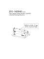
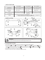
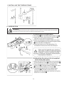
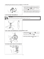
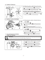
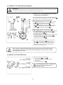
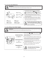
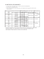
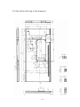
IMPORTANT SAFETY INSTRUCTIONS
Putting sewing systems into operation is prohibited until it has been ascertained that the sewing systems in
which these sewing machines will be built into, have confirmed with the safety regulations in your country.
Technical service for those sewing systems is also prohibited.
1. Observe the basic safety measures, including, but not limited to the following ones, whenever you use
the machine.
2. Read all the instructions, including, but not limited to this Instruction Manual before you use the
machine. In addition, keep this Instruction Manual so that you may read it at anytime when necessary.
3. Use the machine after it has been ascertained that it conforms with safety rules/standards valid in your
country,
4. All safety devices must be in position when the machine is ready for work or in operation.
The operation without the specified safety devices is not allowed.
5. This machine shall be operated by appropriately-trained operators.
6. For your personal protection, we recommend that you wear safety glasses.
7. For the following, turn off the power switch or disconnect the power plug of the machine from the
receptacle.
7-1 For threading needle(s), looper, spreader etc. and replacing bobbin.
7-2 For replacing part(s) of needle, presser foot, throat plate, looper, spreader, feed dog. needle guard,
folder, cloth guide etc.
7-3 For repair work.
7-4 When leaving the working place or when the working place is unattended.
7-5 When using clutch motors without applying brake, it has to be waited until the motor stopped totally.
8. If you should allow oil, grease, etc. used with the machine and devices to come in contact with your
eyes or skin or swallow any of such liquid by mistake, immediately wash the contacted areas and
consult a medical doctor.
9. Tampering with the live parts and devices, regardless of whether the machine is powered, is prohibited.
10. Repair, remodeling and adjustment works must only be done by appropriately trained technicians or
specially killed personnel. Only spare parts designated by Duerkopp Adler Manufacturing (Shanghai)
Co.,Ltd.can be used for repairs.
11. General maintenance and inspection works have to be done by appropriately trained personnel.
12. Repair and maintenance works of electrical components shall be conducted by qualified electric
technicians or under the audit and guidance of special skilled personnel.
Whenever you find a failure of any of electrical components, immediately stop the machine.
13. Before making repair and maintenance works on the machine equipped with pneumatic p arts such as
an air cylinder, the air compressor has to be detached from the machine and the compressed air supply
has to be cut off. Existing residual air pressure after disconnecting the air compressor from the
machine has to be expelled.
Exceptions to this are only adjustments and performance checks done by appropriately trained
technicians or special skilled personnel.
14. Periodically clean the machine throughout the period of use.
15. Grounding the machine is always necessary for the normal operation of the machine. The machine has
to be operated in an environment that is free from strong noise sources such as high-frequency welder.
16. An appropriate power plug has to be attached to the machine by electric technicians. Power plug has to
be connected to a grounded receptacle.
17. The machine is only allowed to be used for the purpose intended. Other used are not allowed.
18. Remodel or modify the machine in accordance with the safety rules/standards while taking all the effective safety
measures. We assume no responsibility for damage caused by remodeling or modification of the machine.
19. Warning hints are marked with the two shown symbols
Danger of injury to operator or service staff
Items requiring special attention
I
FOR SAFE OPERATION
1.Don't put your hand under the needle when you turn "on" the power switch or operate
the machine.
2.Don't put your hand into the thread take-up cover while the machine is running.
3.Turn OFF the power switch before tilting the machine head or removing the belt cover
and the V belt.
4.Never bring your fingers, hair or clothing close to, or place anything on the handwheel,
V-belt, bobbin winder wheel or motor during operation.
5.If your machine is provided with a belt cover, finger guard and safety plate, never
operate your machine with any of them removed.
6.The hook rotates at a high speed while the machine is in operation. To prevent possible
injury to hands, be sure to keep your hands away from the vicinity of the hook during
operation. In addition, be sure to turn OFF the power to the machine when replacing
the bobbin.
7.When tilting the machine head, exercise care not to allow your fingers etc. to be caught
under the machine head.
8.Do not wipe the surface of the machine head with lacquer thinner.
9.Never operate the machine unless its oil pan has been filled with oil.
10.Don't use a motor pulley of a larger outside diameter than the standard outside diameter
for the first onemonth.
11. Confirm that the voltage and phase (single- or 3-phase) are correct by checking them
against the ratings shown on the motor nameplate.
12,In case of maintenance, inspection, or repair, be sure to turn OFF the power switch
and confirm that the sewing machine and the motor have completely stopped before
starting the work. (In case of the clutch motor, it continues rotating for a while by the
inertia even after turning OFF the power switch. So, be careful.)
CAUTION BEFORE OPERATION
WARNING:
To avoid malfunction and damage of the machine, confirm the following.
Clean the sewing machine thoroughly before using it for the first time.
Remove all dust collected on the sewing machine during the transportation.
Confirm that the voltage and phase are correct.
Confirm that the power plug is properly connected.
Never use the sewing machine in the state where the voltage type is different from the
designated one.
The direction of rotation of the sewing machine is counterclockwise as observed from
the handwheel side. Be careful not to rotate it in reverse direction.
II
1. SPECIFICATIONS
251-140040
Application
251-140040 A
For medium-weight materials
251-140040 H
For light-weight materials For heavy-weight materials
Sewing speed
Max. 5,000 rpm
Max. 4,000 rpm
Max. 4,000 rpm
Stitch length
Max. 5 mm
Max. 4 mm
Max. 5 mm
Needle
DBx1#9to#18(134#65to#llO)
Presser foot lift (by knee lifter) 10 mm (Standard)13 mm (Max.)
Lubricating oil
Noise
DBx1#9to#11(134#65to#75) DBx1#20to#23(134#125to#160)
9 mm (Max.)
10 mm (Standard) 13 mm (Max.)
10 White Oil
Workplace-related noise at sewing speed n 5000min -1 : Lpa
Noise measurement according to DIN 45635-48-A-1.
83dB(A)
2. INSTALLATION
WARNING:
To avoid possible personal injury due to abrupt start of the machine, turn off the power to the machine
and check to be sure that the motor has totally stopped rotating in prior.
(1) Installing the oil pan
1) The under cover should rest on the four corners of the machine table groove.
2) Fix the hinge 1 by screw 6 on the base plate.Fix the 2 rubber seats 1 of the front side A to the
protruded side of the table by round nail 2 , then using round nail 2 to fix 2 rubber seats 3 of the
hinge B side and fix the hinge holder 5 in the table slet by screw 7 , then place the oil pan 4 .
3) Put the machine head on the rubber seat 3 .
4) Keep horizontal level when installing the machine head.
-1-
3. INSTALLING THE BELT COVER
WARNING:
To avoid possible personal injury due to abrupt start of the machine, turn off the power to the machine
and check to be sure that the motor has totally stopped rotating in prior.
4. ADJUSTING THE HEIGHT OF THE KNEE LIFTER
WARNING:
To avoid possible personal injury due to abrupt start of the machine, turn off the power to the machine
and check to be sure that the motor has totally stopped rotating in prior.
1) The standard height of the presser foot lifted using the knee lifter is 10 mm.
2) You can adjust the presser foot lift up to 13 mm using knee lifter adjust screw 1 . (Max. 9 mm for A type)
3) When you have adjusted the presser foot lift to over 10 mm, be sure that the bottom end of needle bar 2
in its lowest position does not hit presser foot 3 .
-2-
5. INSTALLING THE THREAD STAND
6. LUBRICATION
WARNING:
To avoid possible personal injury due to abrupt start of the machine, turn off the power to the machine
and check to be sure that the motor has totally stopped rotating in prior.
-3-
7. ADJUSTING THE AMOUNT OF OIL ( OIL SPLASHES ) IN THE HOOK
WARNING:
Be extremely careful about the operation of the machine since the amount of oil has to be
checked by turning the hook at a high speed.
carrying out the procedure described below in 2, remove the slide plate and take extreme
* When
caution not to allow your fingers to come in contact with the hook.
1) If the machine has not been sufficiently warmed up for operation, make the machine run idle for
approximately three minutes. (Moderate intermittent operation)
2) Place the amount of oil (oil spots) confirmation paper under the hook while the sewing machine
is in operation.
3) Confirm the height of the oil surface in the oil reservoir is within the range between
"HIGH" and "LOW.
4) Confirmation of the amount of oil should be completed in five seconds.
(Check the period of time with a watch)
Sample showing the apprpriate amount of oil
1) The amount of oil shown in the samples on the
left should be finely adjusted in accordance
with sewing processes. Be careful not to
excessively increase / decrease the amount of
oil in the hook. (If the amount of oil is too small,
the hook will be seized (the hook will be hot).
If the amount of oil is too much, the sewing
product may be stained with oil.)
2) Adjust the amount of oil in the hook so that the
oil amount (oil splashes) should not change
while checking the oil amount three times
(on the three sheets of paper).
-4-
· Adjusting the amount of oil ( oil spots ) in the hook
1) Turning the oil amount adjustment screw attached
on the hook driving shaft front bushing in the "+"
direction (in direction A ) will increase the amount
of oil (oil spots) in the hook, or in the "-" d irection
(in direction B ) will decrease it.
2) After the amount of oil in the hook has been properly
adjusted with the oil amount adjustment screw,
make the sewing machine run idle for approximately
30 seconds to check the amount of oil in the hook.
8. ATTACHING THE NEEDLE
WARNING:
To avoid possible personal injury due to abrupt start of the machine, turn off the power to the machine
and check to be sure that the motor has totally stopped rotating in prior.
9. SETTING THE BOBBIN INTO THE BOBBIN CASE
1) Pass the thread through thread slit A , and pull the
thread in direction B .
By so doing, the thread will pass under the tension
spring and come out rom notch B .
2) Check that the bobbin rotates in the out direction
from the arrow when thread C is pulled.
10. ADJUSTING THE STITCH LENGTH
-5-
11. Presser foot pressure
12. HAND LIFTER
13. ADJUSTING THE HEIGHT OF THE PRESSER BAR
WARNING:
To avoid possible personal injury due to abrupt start of the machine, turn off the power to the machine
and check to be sure that the motor has totally stopped rotating in prior.
1) Loosen setscrew 1 , and adjust the presser
bar height or the angle of the presser foot.
2) After adjustment, securely tighten the
setscrew 1 .
14. THREADING THE MACHINE HEAD
WARNING:
To avoid possible personal injury due to abrupt start of the machine, turn off the power to the machine
and check to be sure that the motor has totally stopped rotating in prior.
-6-
15. THREAD TENSION
(1) Adjusting the needle thread tension
1) As you turn thread tension nut 1 clockwise (in direction
A ), the needle thread tension will be increased.
2) As you turn nut 1 counterclockwise (in direction B ),
the needle thread tension will be decreased.
(2) Adjusting the bobbin thread tension
1) As you turn tension adjust screw 2 clockwise (in
direction C ), the bobbin thread tension will be increased.
2) As you turn screw 2 counterclockwise (in direction D ),
the bobbin thread tension will be decreased.
16. THREAD TAKE-UP SPRING
(1) Changing the stroke of thread take-up
spring 1
1) Loosen set screw 2 .
2) As you turn tension post 3 clockwise (in direction
A ), the stroke of the thread take-up spring will be
increased.
3) As you turn the knob counterclockwise (in direction
B ), the stroke will be decreased.
(2) Changing the pressure of thread take-up
spring 1
17. ADJUSTING THE THREAD
TAKE-UP STROKE
1) Loosen setscrew 2 , and remove tension post 5 .
2) Loosen setscrew 4 .
3) As you turn tension post 3 clockwise (in direction
A ), the pressure will be increased.
4) As you turn the tension post 3 counterclockwise
(in direction B ), the pressure will be decreased.
WARNING:
To avoid possible personal injury due to abrupt start of the machine, turn off the power to the machine
and check to be sure that the motor has totally stopped rotating in prior.
1) When sewing heavy-weight materials, move thread
guide 1 to the left (in direction A ) to increase the
length of thread pulled out by the thread take-up.
2) When sewing light-weight materials, move thread
guide 1 to the right (in direction B ) to decrease the
length of thread pulled out by the thread take-up.
3) Normally, thread guide 1 is positioned in a way that
marker line C is aligned with the center of the screw.
-7-
18. NEEDLE-TO-HOOK RELATIONSHIP
WARNING:
To avoid possible personal injury due to abrupt start of the machine, turn off the power to the machine
and check to be sure that the motor has totally stopped rotating in prior.
(1) Adjust the timing between the needle
and the hook as follows :
1)Turn the handwheel to bright the needle bar down to
the lowest point of its stroke, and loosen setscrew 1 .
(Adjusting the needle bar height)
2) (For a DB needle) Align marker line A on needle
bar 2 with the bottom end of needle bar lower
bushing 3 , then tighten setscrew 1 .
(For a DA needle) Align marker line C on needle
bar 2 with the bottom end of needle bar lower
bushing 3 , then tighten setscrew 1 .
(Adjusting position of the hook a )
3) (For a DB needle) Loosen the three hook setscrews,
turn the handwheel and align marker line B on
ascending needle bar 2 with the bottom end of
needle bar lower bushing 3 .
(For a DA needle) Loosen the three hook set screws,
turn the handwheel and align marker line D on
ascending needle bar 2 with the bottom end of
needle bar lower bushing 3 .
4) After making the adjustments mentioned in the above
steps, align hook blade point 5 with the center of
needle 4 . Provide a clearance of 0.04 mm to 0.1 mm
(251-140040H : 0.06 to 0.1 7mm) (reference value)
between the needle and the hook, then securely
tighten setscrews in the hook.
NOTE
If the clearance between the blade point of hook and the needle is smaller than the
specified value, the blade point of hook will be damaged. If the clearance is larger,
stitch skipping will result.
19.HEIGHT OF THE FEED DOG
To adjust the height of the feed dog:
1 Loosen screw 2 of crank 1 .
2 Move the feed bar up or down to make
adjustment.
3 Securely tighten screw 2 .
If the clamping pressure is insufficient,
the motion of the forked portion
NOTE becomes heavy.
-8-
20. TILT OF THE FEED DOG
WARNING:
To avoid possible personal injury due to abrupt start of the machine, turn off the power to the machine
and check to be sure that the motor has totally stopped rotating in prior.
1) The standard tilt (horizontal) of the feed dog is
obtained when marker dot A on the feed bar
shaft is aligned with marker dot B on feed rocker
1 . (251-140040H, the marker dot B inclines
forward the feed rocker shaft by 90 , as standard).
2) To tilt the feed dog with its front up in order to
prevent puckering, loosen the setscrew, and turn
the feed bar shaft 90 in the direction of the arrow,
using a screwdriver.
3) To tilt the feed dog with its front down in order to
prevent uneven material feed, turn the feed bar
shaft 90 in the opposite direction from the arrow.
(The standard tilt for 251-140040H.)
Whenever the feed dog tilt is adjusted,
the feed dog height will be changed.
So, it is necessary to check the height
NOTE after tilt adjustment.
21. ADJUSTING THE FEED TIMING
WARNING:
To avoid possible personal injury due to abrupt start of the machine, turn off the power to the machine
and check to be sure that the motor has totally stopped rotating in prior.
1) Loosen screws 2 and 3 in feed eccentric cam 1 ,
move the feed eccentric cam in the direction of the
arrow or opposite direction of the arrow, and firmly
tighten the screws.
2) For the standard adjustment, adjust so that the top
surface of feed dog and the top end of needle eyelet
are flush with the top surface of throat plate when
the feed dog descends below the throat plate.
3) To advance the feed timing in order to prevent
uneven material feed, move the feed eccentric cam
in the direction of the arrow.
4)To delay the feed timing in order to increase stitch
tightness, move the feed eccentric cam in the
opposite direction from the arrow.
NOTE
-9-
Be careful not to move the feed
eccentric cam too far, or else Nee
dle breakage my result
22. MOTOR PULLEYS AND BELTS
1) A clutch motor with 400W output (1/2 HP) is used as the standard motor
2) An M-type V belt should be used.
3) The relationship between the motor pulleys, belt lengths and sewing speeds is shown in the
following table:
Motor pulley O.D.
Motor pulley part No. Sewing speed ( rpm )
50 Hz
(mm)
60 Hz
125
GE1007
5,060
120
GE1008
4,850
115
GE1009
4,630
110
GE10010
4,440
105
GE10011
4,250
5,040
100
GE10012
4,000
4,780
95
GE10013
3,820
4,540
90
GE10014
3,610
4,320
85
GE10015
3,390
4,000
80
GE10016
3,160
3,790
75
GE10017
2,950
3,520
70
GE10018
2,740
3,260
Belt length
Belt part No.
1118 mm (44 )
GE1003
1092 mm (43 )
GE1004
1067 mm (42 )
GE1005
1041 mm (41 )
GE1006
* The effective diameter of a motor pulley is equivalent to the outside diameter minus 5 mm.
* The motor should rotate counterclockwise as observed from the handwheel side.
Be careful not to allow the motor to rotate in reverse direction.
-10-
Cut the table referring to the diagram.
-11-