1
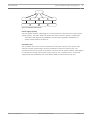
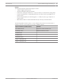
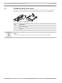
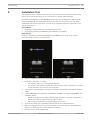
DCN multimedia
Conference System
en
Hardware Installation Manual
DCN multimedia
Table of Contents | en
3
Table of contents
1
Safety
4
2
About this manual
5
2.1
Intended audience
5
2.2
Alerts and notice signs
5
2.3
Copyright and disclaimer
5
2.4
Document history
5
3
System installation overview
6
3.1
Typical system setup
7
4
System installation design and planning
8
4.1
System capabilities
4.2
Hardware requirements
10
4.3
Power supply capacity calculation plan
12
4.3.1
Calculation using DCNM-APS or DCNM-PS
12
4.3.2
Calculation using PoE switches
15
5
Installation material and tools
16
5.1
DCNM-CBxx System Network Cable
16
5.2
DCNM-CBCON System Network Cable Connector (50 pcs)
17
5.3
DCNM-CBTK System Network Cable Toolkit
18
5.4
DCNM-CB250 System Installation Cable
19
6
Mechanical installation of Central Equipment
20
6.1
DCNM-APS and DCNM-PS
20
7
Mechanical installation of Contribution Devices
23
7.1
DCNM-MMD Multimedia Device
23
7.2
DCNM-HDMIC High Directive Microphone
26
7.3
DCNM-MMDSP Anti-reflection foil
27
7.4
DCNM-NCH Name Card Holder
28
8
Installation Test
29
Bosch Security Systems B.V.
8
Hardware Installation Manual
2013-08 | V1.0 |
4
en | Safety
1
DCN multimedia
Safety
Prior to installing or operating products, always read the Important Safety Instructions which
are available as a separate multilingual document: Important Safety Instructions (Safety_ML).
These instructions are supplied together with all equipment that can be connected to the
mains supply.
Safety precautions
Some products of the DCN multimedia product range are designed to be connected to the
public mains network.
To avoid any risk of electric shock, all interventions must be carried out with disconnected
mains supply.
Interventions with the equipment switched on are authorized only when it is impossible to
switch the equipment off. The operation must only be performed by qualified personnel.
2013-08 | V1.0 |
Hardware Installation Manual
Bosch Security Systems B.V.
DCN multimedia
About this manual | en
5
About this manual
2
The purpose of this manual is to provide information required for installing the DCN
multimedia conference system.
This installation manual is available as a digital document in the Adobe portable document
format (PDF).
For more information, refer to the product related information on www.boschsecurity.com
Intended audience
2.1
This hardware installation manual is intended for installers of a DCN multimedia conference
system.
Alerts and notice signs
2.2
Four types of signs can be used in this manual. The type is closely related to the effect that
may be caused if it is not observed. These signs - from least severe effect to most severe
effect - are:
Notice!
Containing additional information. Usually, not observing a ‘notice’ does not result in damage
to the equipment or personal injuries.
Caution!
!
The equipment or the property can be damaged, or persons can be lightly injured if the alert
is not observed.
Warning!
!
The equipment or the property can be seriously damaged, or persons can be severely injured
if the alert is not observed.
Danger!
Not observing the alert can lead to severe injuries or death.
2.3
Copyright and disclaimer
All rights reserved. No part of this document may be reproduced or transmitted in any form by
any means, electronic, mechanical, photocopying, recording, or otherwise, without the prior
written permission of the publisher. For information on getting permission for reprints and
excerpts, contact Bosch Security Systems B.V..
The content and illustrations are subject to change without prior notice.
2.4
Document history
Release date
Documentation version
Reason
2013.08
V1.0
1st edition
Bosch Security Systems B.V.
Hardware Installation Manual
2013-08 | V1.0 |
6
en | System installation overview
3
DCN multimedia
System installation overview
It is advisable to participate in the DCN multimedia conference system training before you
install, prepare, configure and operate a DCN multimedia system.
The DCN multimedia system is an IP based conference system which runs on an OMNEO
compatible Ethernet network. It is used for distributing and processing audio, video and data
signals.
The system can be quickly and easily configured as a daisy‑chain configuration (see Typical
system setup, page 7), or as a star configuration:
–
Daisy‑chain configuration: Uses dedicated cabling, consisting of CAT‑5e cables including
two additional power conductors.
–
Star configuration: Each device is connected with an individual standard CAT‑5e cable.
An Ethernet switch is also required for providing Power over Ethernet (PoE).
Notice!
When Power over Ethernet is used, devices cannot be daisy‑chained.
See also
–
2013-08 | V1.0 |
Typical system setup, page 7
Hardware Installation Manual
Bosch Security Systems B.V.
DCN multimedia
3.1
System installation overview | en
7
Typical system setup
1
2
9
5.1
8
7
8
8
8
4
8
6
6
8
6
3
6
6
5.2
5
Figure 3.1: Typical DCN multimedia system overview
A typical DCN multimedia conference system consists of:
1.
System server controller (PC):
–
2.
–
3.
The heart of the system. It licenses functionality, configures and controls the system.
Client PC (optional):
Can be used to: Manage meetings, prepare meetings and configure the system.
Audio Powering Switch (DCNM‑APS):
–
Controls the system audio, routes audio from and to the system and supplies power
to the devices.
4.
Powering Switch (DCNM‑PS):
–
5.
Is used to increase the number of devices connected to the system.
Conference multimedia devices (DCNM‑MMD):
–
Participants can use the multimedia device to make their contributions to a meeting.
–
5.1 is a DCNM‑MMD used for “system power on/off”. This DCNM‑MMD is always
connected to the powered socket of the DCNM‑APS or DCNM‑PS.
–
6.
5.2 is a DCNM‑MMD used via “Power over Ethernet” (PoE) Ethernet switch.
System Network Cable (DCNM‑CBxxx):
–
Connects DCN multimedia devices, audio powering switch and powering switch with
each other.
7.
Ethernet switch:
–
Ethernet switch with PoE on some ports. Routes the system data via Ethernet.
8.
CAT‑5e Ethernet cable (minimum requirement).
9.
Optional HD Conference Dome (VCD‑811-IWT) + external power supply:
–
Bosch Security Systems B.V.
Captures the image of a participant speaking.
Hardware Installation Manual
2013-08 | V1.0 |
8
en | System installation design and planning
4
DCN multimedia
System installation design and planning
Before you start to install system devices and connect system cabling, you should make a
system design and planning:
–
–
Familiarize yourself with the product and system capabilities.
Make a cable (connection) plan:
–
Calculate the system network cable length.
–
Calculate the system power consumption.
–
Calculate the required power capacity of the system.
Notice!
DCN multimedia uses the RSTP protocol. If the DCN multimedia system needs to be
connected with the locally present network, please consult the local IT department before
continuing with the installation design.
Notice!
Make sure that the cable lengths and power consumptions do not exceed the specifications:
Not doing so will result in malfunctioning at any moment of the DCN multimedia products and
system.
4.1
System capabilities
DCN multimedia product and system capabilities depend on:
–
The lengths of the system network cables.
–
The number of connected devices.
–
The system power supply capacity.
Cable length
System network cables (DCNM‑CBxx) lengths (2, 5, 10 or 25 m) have a direct effect on the
available power supply capacity. The longer the system network cable, the less power supply
capacity is available to drive the connected devices. Therefore, choose the lengths of the
system network cables carefully.
Notice!
Custom network cables, must never exceed the maximum Gb Ethernet specification of 100m
(IEEE 802.3ab). The maximum DCN multimedia system network cable length to be used is
50m.
Keep your network hierarchy as flat as possible. This means having as less levels as possible.
It is recommended not to have more than 7 levels. See the following example: 1 = Root
switch. 2 = Switch.
2013-08 | V1.0 |
Hardware Installation Manual
Bosch Security Systems B.V.
DCN multimedia
System installation design and planning | en
9
1
2
2
2
2
2
2
2
2
Figure 4.1: Example: Switch-levels
Power supply capacity
The total system network cable length and connected devices determine the required power
supply capacity. The power within the DCN multimedia conference system is supplied by:
–
The Audio Powering Switch (DCNM‑APS) and the Powering Switch (DCNM‑PS), or
–
Off‑the‑shelf PoE Ethernet switches.
Calculation tool
The calculation tool can be used to calculate the total power capacity of the system. This
makes the design and planning of the DCN multimedia conference system easier. The
calculation tool uses the power consumption of devices and the system network cable lengths
to calculate the needed system power supply capacity. The calculation tool is on the DVD
supplied with the DCNM‑APS, and on the Bosch website: www.boschsecurity.com.
Bosch Security Systems B.V.
Hardware Installation Manual
2013-08 | V1.0 |
10
en | System installation design and planning
4.2
DCN multimedia
Hardware requirements
Switches
The following minimal requirements apply to switches:
–
1 Gbit or higher with hardware switching capabilities.
–
Quality of Service through differentiated services with 4 or more output queues and strict
priority packet scheduling.
–
(Optional) IGMPv3 or IGMPv2 snooping. To optimize bandwidth usage, IGMP snooping
can be used. This is useful in systems with >10 multicast channels, although not
absolutely required. Sufficient performance for handling a large number of IGMP query
responses, depending on the number of (directly or indirectly) connected devices to that
switch. Hardware support for IGMP is strongly recommended.
–
(Optional) (Rapid) Spanning Tree support in case redundant networks are used.
–
(Optional) SNMPv3 support for switch supervision purposes.
The following table shows recommended switches to use with OMNEO. These managed
switches may offer support for the optional requirements as stated above.
Managed switches
IGMP Snooping
RSTP (Y/N)
SNMPv3 (Y/N)
Y
Y
Y
Y
Y
Y
v1, v2
Y
Y
Cisco SG 300 series
v1, v2, v3
Y
Y
Cisco SG 200 series
v1, v2
Y
N
Cisco ESW 500 series v1, v2
Y
Y
Cisco SLM2000 series v1, v2
N
N
D-Link DGS 1210
Y
Y
HP Networking E2520 v1, v2, v3
series
HP Networking V1900 Y[2]
series
HP Networking V1910 Y3
series
Netgear GS108T /
Netgear GS108Tv2
v1, v2
series
The price range for these switches varies depending on the number of ports the switch may
have. More expensive switches are also available, but have not been taken into consideration.
2013-08 | V1.0 |
Hardware Installation Manual
Bosch Security Systems B.V.
System installation design and planning | en
DCN multimedia
11
Routers
The following minimal requirements apply to routers:
–
1 Gbit or higher Ethernet ports.
–
Supports PIM‑DM or Bidirectional PIM.
–
Performs IP routing in hardware (i.e. a ‘layer 3 switch’) to minimize the routing delay.
–
Packet forwarding rate > 1,000,000 packets per second per port (e.g. 8 Mpps for an
8‑port router).
–
Non-blocking backplane per switching port, i.e. 2 Gbit per port (e.g. 16 Gbps for an
8‑port router).
–
MAC address table of at least 1000 addresses per directly connected subnet.
The following table contains routers or router families (all of which are actually ‘layer 3
switches’) that are recommended to be used in OMNEO systems:
Layer 3 switches (or switch series)
Remarks
Cisco 3560‑X series
Requires IP services feature set
HP 3500 yl series
Requires Premium License
HP 3800 series
-
HP 4800 series
-
HP 5500‑EI series
-
Netgear GSM7328S‑200
-
Netgear GSM7352S‑200
-
Bosch Security Systems B.V.
Hardware Installation Manual
2013-08 | V1.0 |
12
en | System installation design and planning
4.3
DCN multimedia
Power supply capacity calculation plan
How to start
First decide how to supply power to the devices:
–
Using DCNM‑APS and DCNM‑PS
–
Using PoE Ethernet switch
If you want to use PoE Ethernet switches, continue with chapter Calculation using PoE
switches, page 15.
See also
4.3.1
–
Calculation using DCNM-APS or DCNM-PS, page 12
–
Installation material and tools, page 16
Calculation using DCNM-APS or DCNM-PS
Notice!
If you want to use customized cables, or a more accurate power supply capacity calculation
plan is needed, you should use the power calculation tool.
To calculate the total power supply capacity:
1.
Count all multimedia devices.
2.
Know the exact location where the devices are installed.
3.
Count each system network cable of the same length.
Device type
Power consumption (Watts)
DCNM‑MMD
12.50
DCNM‑CB02
1.19
DCNM‑CB05
2.43
DCNM‑CB10
4.50
DCNM‑CB25
10.71
Table 4.1: Power consumption (Watts)
Ordering number
Cable lengths
m
ft
DCNM-CB02
2
6.56
DCNM-CB05
5
16.40
DCNM-CB10
10
32.81
DCNM-CB25
25
82.02
Table 4.2: Cable types and lenghts
2013-08 | V1.0 |
Hardware Installation Manual
Bosch Security Systems B.V.
System installation design and planning | en
DCN multimedia
13
Rear view
1 2 3 4 5 6 7 8
10
12
11
13
15
14
17
16
9
19
18
20
Figure 4.2: DCNM‑APS
9
10
12
13
14
15
17
16
18
19
20
Figure 4.3: DCNM‑PS
Item
Description
1, 5
XLR line outputs 1 and 2.
2, 6
RCA line outputs 1 and 2.
3, 7
XLR line inputs 1 and 2.
4, 8
RCA line inputs 1 and 2.
9
Mains inlet, mains switch and fuse holder.
10
Reset button.
11
Ground switch (grounded or floating).
12
Socket 1 without power.
13
Socket 2 low power.
15, 17, 19
Socket 3, 4, 5 high power.
14, 16, 18, 20
Overload LED for sockets 2‑5:
Green: Power OK.
Red: Overload. Remove cable and wait a few seconds for the system to
reset the overload.
Bosch Security Systems B.V.
Hardware Installation Manual
2013-08 | V1.0 |
14
en | System installation design and planning
DCN multimedia
Network and Power connector
Max. power output (W) Max. devices
Socket 1 (12)
No power capacity.
---
Socket 2 (13)
15
1
Socket 3 (15)
144
10
Socket 4 (17)
144
10
Socket 5 (19)
144
10
Table 4.3: Power supply capacity DCNM‑APS / DCNM‑PS
Calculation examples
The following example gives you an indication of the maximum load to each DCNM‑APS or
DCN‑PS socket:
–
Socket 2: 50 m + DCNM‑MMD = 12.50 W1
–
Socket 3: 10 m + DCNM‑MMD + 9x (2 m + DCNM‑MMD) = 4.50 + 12.50 + (9*1.19) +
(9*12.5) = 140.21 W2.
–
Socket 4: 10 m + DCNM‑MMD + 9x (2 m + DCNM‑MMD) = 4.50 + 12.50 + (9*1.19) +
(9*12.5) = 140.21 W2.
–
Socket 5: 10 m + DCNM‑MMD + 9x (2 m + DCNM‑MMD) = 4.50 + 12.50 + (9*1.19) +
(9*12.5) = 140.21 W2.
1
2
For socket 2, the cable power consumption of the cable does not need to be counted.
The shortest redundant cable does not need to be counted.
Redundant network
If a system network cable between the devices is accidentally disconnected or broken, signals
cannot be transmitted anymore. To prevent this from happening (and to ensure continuous
operation) a redundant system network cable (4) can be connected to a free high‑power
socket (3, 4, or 5).
1
4
3
5
2
Figure 4.4: Example DCNM‑MMD with DCNM‑APS redundant cabling
2013-08 | V1.0 |
1.
DCNM‑APS.
2.
DCNM‑MMD.
3.
CAT‑5e cable.
4.
System network cable for redundant cabling.
5.
System network cable for daisy‑chain cabling.
Hardware Installation Manual
Bosch Security Systems B.V.
DCN multimedia
System installation design and planning | en
15
Notice!
Make sure one socket can supply power to the complete redundant chain.
4.3.2
Calculation using PoE switches
Select one or more PoE Ethernet switches to supply power to the multimedia devices. Each
DCNM‑MMD must be connected to an individual PoE enabled output of an Ethernet switch.
Notice!
Some PoE Ethernet switches can only supply power to a limited number of ports. Others can
supply power to every port, but the total power the Ethernet switch can supply is limited.
Please consult the documentation of the PoE Ethernet switch used.
Notice!
If the PoE is used, the DCNM‑MMD cannot be configured as a daisy‑chain; redundant cabling
is not required.
Using PoE, the DCNM‑MMD cannot be daisy‑chained connected. Using PoE does not provide
redundant cabling.
2
1
Item
Description
1
Network connector
2
Network/PoE connector
Bosch Security Systems B.V.
Hardware Installation Manual
2013-08 | V1.0 |
16
en | Installation material and tools
5
DCN multimedia
Installation material and tools
This section describes installation material such as cables, connectors and tools.
Recommedations
–
Always use manufacturer specified installation products, materials and tools.
–
In general, use different cable ducts for the system network cables, audio cables and
mains supply cables.
–
In public areas where people can touch or move above the connectors and cables, use
metal protection covers.
Warning!
!
5.1
Do not exceed the bend limitations of system network cables (DCNM‑CBxxx):
The minimum bend radius of the system network cable is 50 mm radius.
DCNM-CBxx System Network Cable
The system network cables, terminated with connectors on both ends, are available in
different lengths and are used to connect DCN multimedia devices to each other. The cable
consists of four CAT‑5e twisted pairs to transmit data and two copper wires to supply the
power.
Ordering number
Cable lengths
m
ft
DCNM-CB02
2
6.56
DCNM-CB05
5
16.40
DCNM-CB10
10
32.81
DCNM-CB25
25
82.02
Table 5.1: Cable types and lenghts
Figure 5.1: DCNM-CBxx cable and connector view
2013-08 | V1.0 |
Hardware Installation Manual
Bosch Security Systems B.V.
DCN multimedia
5.2
Installation material and tools | en
17
DCNM-CBCON System Network Cable Connector (50 pcs)
You can make your own system network cables by using:
–
The system network connector (this section).
–
The DCNM-CB250 System Installation Cable, page 19.
–
The DCNM-CBTK System Network Cable Toolkit, page 18.
9
7
6
5
4
3
8
1
7
9
5
3
8
2
1
6
4
Figure 5.2: DCNM-CBCON Front and exploded view
Item
Description
1
Strain relief boot
2
Ferrule
3
Plug connector shield
4
Power contacts (Qty: 2)
5
Load bar
6
Power contact cavity (2 places)
7
Housing
8
Locking latch
9
Signal contact cavity (8 Places)
Bosch Security Systems B.V.
Hardware Installation Manual
2013-08 | V1.0 |
18
en | Installation material and tools
5.3
DCN multimedia
DCNM-CBTK System Network Cable Toolkit
The system network cable toolkit is used to connect the DCNM-CBCON System Network Cable
Connector (50 pcs), page 17 to the DCNM-CB250 System Installation Cable, page 19.
1
2
Item
Description
1
Power wiring tool.
2
Signal wiring tool.
Table 5.2: Toolkit content
Notice!
Please consult the “custom length for system network cables” section on the DVD, which is
supplied with the DCNM‑APS.
2013-08 | V1.0 |
Hardware Installation Manual
Bosch Security Systems B.V.
DCN multimedia
5.4
Installation material and tools | en
19
DCNM-CB250 System Installation Cable
The system network installation cable, without connectors, is available in a length of 250
meters and is used for making your own system network cable.
Notice!
The maximum system network cable length is: 50 m / 164.04 ft.
Notice!
Please consult the “custom length for system network cables” section on the DVD, which is
supplied with the DCNM‑APS.
See also
–
DCNM-CBCON System Network Cable Connector (50 pcs), page 17
–
DCNM-CBTK System Network Cable Toolkit, page 18
Bosch Security Systems B.V.
Hardware Installation Manual
2013-08 | V1.0 |
20
en | Mechanical installation of Central Equipment
DCN multimedia
6
Mechanical installation of Central Equipment
6.1
DCNM-APS and DCNM-PS
The DCNM‑APS Audio Powering Switch is used to:
–
control system audio signals,
–
route audio signals to/from devices,
–
supply power to devices,
–
Ethernet switch to connect PC and DCNM‑MMD's.
The DCNM‑PS Powering Switch is used to:
–
Supply power to devices.
Scope of delivery
The DCNM‑APS and DCNM‑PS are shipped with the following parts:
–
1x Mains power cord.
–
1x Safety instructions.
–
1x Set of 19 inch mounting brackets.
–
4x bottom feet.
–
1x DVD containing manuals and software (only with DCNM‑APS).
Front view
1
2
3
2
Item
Description
1
19“ mounting brackets.
2
Ventilation inlet.
3
Indication LED:
1
Off: Switched off.
Green: Switched on.
Amber: Standby.
Blinking: Services on the server PC are not running.
Alternating green amber: When a software download is required.
2013-08 | V1.0 |
Hardware Installation Manual
Bosch Security Systems B.V.
Mechanical installation of Central Equipment | en
DCN multimedia
21
Rear view
1 2 3 4 5 6 7 8
10
12
11
13
15
14
17
16
9
19
18
20
Figure 6.1: DCNM‑APS
9
10
12
13
14
15
17
16
18
19
20
Figure 6.2: DCNM‑PS
Item
Description
1, 5
XLR line outputs 1 and 2.
2, 6
RCA line outputs 1 and 2.
3, 7
XLR line inputs 1 and 2.
4, 8
RCA line inputs 1 and 2.
9
Mains inlet, mains switch and fuse holder.
10
Reset button.
11
Ground switch (grounded or floating).
12
Socket 1 without power.
13
Socket 2 low power.
15, 17, 19
Socket 3, 4, 5 high power.
14, 16, 18, 20
Overload LED for sockets 2‑5:
Green: Power OK.
Red: Overload. Remove cable and wait a few seconds for the system to
reset the overload.
Bosch Security Systems B.V.
Hardware Installation Manual
2013-08 | V1.0 |
22
en | Mechanical installation of Central Equipment
DCN multimedia
How to install
1. Install the DCNM‑APS or DCNM‑PS in a 19 inch device rack system or on a flat surface.
Two 19 inch mounting brackets and four bottom feet are supplied with the DCNM‑APS
and DCNM‑PS. Refer to the following illustration.
2.
Connect all required cabling.
3.
Connect the mains supply.
2
1
3
Figure 6.3: 19 inch rack, flat surface and feet mounting
Item
Description
1
19 inch rack mounting (bracket)
2
Flat surface mounting (bracket)
3
Feet mounting
Notice!
The device extends 30 mm in front of the 19” mounting brackets when installed in a 19” rack
system.
Caution!
!
2013-08 | V1.0 |
Do not obstruct the airflow vents on the front side and rear left and right sides.
Hardware Installation Manual
Bosch Security Systems B.V.
DCN multimedia
Mechanical installation of Contribution Devices | en
7
Mechanical installation of Contribution Devices
7.1
DCNM-MMD Multimedia Device
23
Typically, the DCNM‑MMD is used to:
–
Add participants to a meeting.
–
Monitor and control a meeting or conference by the chairperson.
9
8
1
2
3
4
5
6
7
Figure 7.1: DCNM-MMD front, top, rear and side views
Item
Description
1
7” capacitive touch screen.
2
LED strip.
3
Two‑way loudspeaker.
4
3.5 mm stereo jack for headphone or headset with integrated microphone.
5
Headphone volume control.
6
Chairperson priority or microphone mute button.
7
Microphone request button.
8
Cable guides.
9
Microphone input connector.
Bosch Security Systems B.V.
Hardware Installation Manual
2013-08 | V1.0 |
24
en | Mechanical installation of Contribution Devices
DCN multimedia
How to connect
The system can be quickly and easily configured as a daisy‑chain configuration (see Typical
system setup, page 7), or as a star configuration:
–
Daisy‑chain configuration: Uses dedicated cabling, consisting of CAT‑5e cables including
two additional power conductors.
–
Star configuration: Each device is connected with an individual standard CAT‑5e cable.
An Ethernet switch is also required for providing Power over Ethernet (PoE).
Notice!
When Power over Ethernet is used, devices cannot be daisy‑chained.
The star configuration makes use of connectors underneath the devices, ensuring for a neat,
tidy system installation, especially advantageous for TV coverage.
To connect the system network cables to the device (Refer to figure "DCNM-MMD Bottom
view (fixed installation)" following.):
1.
Insert the system network cable/connector (2).
2.
Lead the system network cable through the cable guides (3).
How to install
The multimedia device can be free-standing or fixed in more permanent installations using
mounting screws.
For fixed installation:
1.
The distance between the centres of the screw inserts (1) on the bottom of the
DCNM‑MMD is 100 mm.
2.
Use M4 type of screws with a device screw insert length of maximum 5 mm when
attaching the device to the bottom of the recess (1).
1
1
2
3
4
Figure 7.2: DCNM-MMD Bottom view (fixed installation)
2013-08 | V1.0 |
Item
Description
1
Screw insert for fixed installation.
2
2x RJ45 connection input/output for system power cable.
3
Cable guides.
4
USB connector (for future use)
Hardware Installation Manual
Bosch Security Systems B.V.
DCN multimedia
Mechanical installation of Contribution Devices | en
25
See also
–
DCNM-CBxx System Network Cable, page 16
–
DCNM-CB250 System Installation Cable, page 19
Bosch Security Systems B.V.
Hardware Installation Manual
2013-08 | V1.0 |
26
en | Mechanical installation of Contribution Devices
7.2
DCN multimedia
DCNM-HDMIC High Directive Microphone
The high directive microphone is typically used with the:
–
DCNM-MMD Multimedia Device, page 23.
1
2
3
7
4
6
8
5
Figure 7.3: DCNM‑HDMIC front and bottom view
2013-08 | V1.0 |
Number
Description
1
LED indicator.
2
Microphone grill (left and right).
3
Microphone grill (front and rear).
4
Connection guidance.
5
Slider guidance.
6
Connector plug.
7
Lockslider for lock release (Press and shift to release).
8
Lock.
Hardware Installation Manual
Bosch Security Systems B.V.
DCN multimedia
Mechanical installation of Contribution Devices | en
27
How to connect or remove the microphone
The microphone can be easily connected to the DCNM-MMD Multimedia Device, page 23:
9
6
4
75 8
Figure 7.4: DCNM‑HDMIC to DCNM‑MMD connection
To do so:
1.
Gently guide the connection guidance (4) into the DCNM‑MMD microphone connector
(9).
2.
Gently push the connector plug (6) into the DCNM‑MMD microphone connector (9) until
the connection lock (5) fits/click into place.
3.
To remove the microphone from the DCNM‑MMD: Shift lockslider (7) towards the
DCNM‑MMD and hold in place lock release (8) and pull out the microphone.
7.3
DCNM-MMDSP Anti-reflection foil
The DCN multimedia Anti‑reflection foil is a self‑absorbed premium tempered glass screen
protector which has anti‑scratch and anti‑wear features.
Installation procedure
1. Please use the included alcohol swab and the microfiber fabric to clean the DCNM‑MMD
LCD screen before installation.
2.
Peel the positioning adhesive release paper from the rear of anti‑reflection foil.
3.
Position the anti‑reflection foil on the DCNM‑MMD LCD screen, and then fix the
positioning adhesive to the side of the DCNM‑MMD.
4.
Open the anti‑reflection foil, and use the “cleaning stick” to clean surface dust from the
LCD screen.
5.
Peel the protective film from the other side of the anti‑reflection foil.
6.
Lightly press the anti‑reflection foil on to the LCD screen. If air bubbles are trapped under
the anti‑reflection foil, use the “squeegee” to remove them.
Bosch Security Systems B.V.
Hardware Installation Manual
2013-08 | V1.0 |
28
en | Mechanical installation of Contribution Devices
7.4
DCN multimedia
DCNM-NCH Name Card Holder
The name card holder (1) has two magnets (2) located on top of the name card holder and
can therefore be easily attached to, and removed from, the rear side of the DCNM‑MMD.
1
2
2
Figure 7.5: DCNM‑NCH to DCNM‑MMD assembly
Item
Description
1
Name card holder.
2
Magnets.
Notice!
A paper insert template is included on the DVD that is supplied with the DCNM‑APS.
2013-08 | V1.0 |
Hardware Installation Manual
Bosch Security Systems B.V.
DCN multimedia
8
Installation Test | en
29
Installation Test
An installation test is needed to prevent connection mismatches and find potential product
defects at an early stage. Not to do so could result in a system malfunctioning.
Each DCN multimedia device (DCNM‑MMD) has its own build‑in diagnostics, which can be
used for faultfinding. The diagnostics starts as soon the device is powered on. The DCN
multimedia conference system does not have to be configured with, and connected to, the
system controller PC.
Preconditions
1. All system network cables are connected to the devices.
2.
The powering switches (DCNM‑APS and DCNM‑PS) are installed.
Start the test
Power on all powering switches (DCNM‑APS and DCNM‑PS) used in the system: Each
connected device powers on and initializes.
1.
After the multimedia device has initialized, the diagnostic screen is shown.
2.
If the text “Link down” is shown:
–
The network cable is not connected or defective.
–
The device is only connected with one system network cable (“Link down” is shown
on the side where the device is not connected).
3.
If the system network cable is correctly connected to the network, the network speed is
shown.
4.
If the DCNM‑MMD is connected to a DCNM‑APS, DCNM‑PS or another DCNM‑MMD, and
100 Mb is shown:
–
Not all wiring inside the system network cable connector is correctly connected or
broken. You need to check the wiring and connector.
–
If the cable is connected to a 100 Mb switch, it is correct.
5.
Click the info button to see additional information of the multimedia device.
6.
When everything is correctly connected, and the device does not have the application
software, it shows the text “Please download software”.
7.
Bosch Security Systems B.V.
Now the device can be downloaded:
Hardware Installation Manual
2013-08 | V1.0 |
30
en | Installation Test
DCN multimedia
–
Downloading devices is not covered in this manual. Refer to the DCN mulimedia
configuration manual on how to download the devices.
Customer service
If a fault cannot be resolved, please contact your supplier or system integrator, or go directly
to your Bosch representative.
2013-08 | V1.0 |
Hardware Installation Manual
Bosch Security Systems B.V.
Bosch Security Systems B.V.
Torenallee 49
5617 BA Eindhoven
The Netherlands
www.boschsecurity.com
© Bosch Security Systems B.V., 2013