1
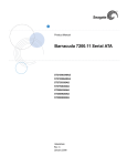
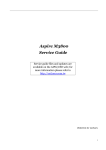
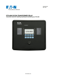
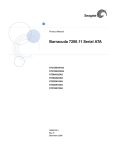
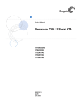
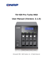
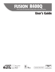
ACE Laboratory
PC-3000 for Windows UDMA ®
SEAGATE, part 2
Seagate, part 2
F3 architecture
Drive families: Barracuda 7200.11 and Barracuda ES.2
1. Introduction.....................................................................................................................................................................2
2. Supported drive families .................................................................................................................................................3
3. Getting started .................................................................................................................................................................4
4. Utility start ......................................................................................................................................................................4
5. Frequent malfunctions.....................................................................................................................................................6
5.1. Motor seizure ...........................................................................................................................................................6
5.2. “Stuck” heads...........................................................................................................................................................6
5.3. HDD returns HDD ID (the host system detects it), but reports capacity = 0 ...........................................................7
5.4. Host system does not detect a HDD, which permanently remains BSY ..................................................................9
6. User commands.............................................................................................................................................................13
7. Appendix 1. Replacement of the controller board ........................................................................................................13
8. Appendix 2. Testing the HDD controller board ............................................................................................................14
9. Appendix 3. Testing the motor winding coils ..............................................................................................................15
10. Appendix 4. Unlocking Barracuda ES.2 drives (version SN05 and newer) in case of problem indicated by
LED: 000000CC. PCB view in 7200.11 and ES.2 drives .................................................................................................15
10.1. Searching for the short connection points ............................................................................................................16
10.2. Location of the checkpoints on Barracuda 7200.11 HDD....................................................................................17
10.2.1. PCB 100466725 REV A (DLAJ-4)...............................................................................................................17
10.2.2. PCB 100466824 REV A (UJAJ-6)................................................................................................................18
10.2.3. PCB 100466824 REV B (UJAJ-6)................................................................................................................19
10.2.4. PCB 100466824 REV C (UJAJ-6)................................................................................................................20
10.2.5. PCB 100496208 REV A ...............................................................................................................................21
10.2.6. PCB 100504364 REV B................................................................................................................................22
10.2.7. PCB 100512588 REV A ...............................................................................................................................23
10.3. Location of the checkpoints on ES.2 HDD ..........................................................................................................24
10.3.1. PCB 100475720 REV A (ZKAJ-7)...............................................................................................................24
ACE Laboratory Ltd, Russia
www.acelaboratory.com
Unauthorized copy or distribution of these documents is prohibited
1
ACE Laboratory
® PC-3000 for Windows UDMA
SEAGATE, part 2
1. Introduction
By the year 2008 Seagate evolved from manufacture of the classic 3.5” Barracuda HDD line (…, 7200.7,
7200.8, 7200.9, 7200.10, Barracuda ES) to the new F3 architecture intended to unify the production of ATA and SCSI
drives. That new drive family is mostly based on mechanics and the kernel from the ATA hard drives, but a large part
of firmware microarchitecture has been revised in accordance with the design used in SCSI Seagate drives. In
particular, ROM has been extended and supplemented with the functionality enabling the controller board to operate in
ATA mode without the HDA attached. Furthermore, the manufacturer moved to ROM adaptive data and HDD ID
information (due to that fact a board disconnected from HDA can return via the ATA interface HDD ID containing
correct HDD information1). However, together with useful effects of that combination the new architecture also
inherited a number of problems from both its parent lines. In particular, it includes a number of problems related to
translator corruption (issues typical of SCSI HDD).
Fig. 1. Barracuda ES.2 (upper) and Barracuda 7200.11 HDD (lower).
1
FW in ROM of some Barracuda ES.2 drives contain standard HDD ID, which is updated using the information from
disk surface in individual drives.
Unauthorized copy or distribution of these documents is prohibited.
2
ACE Laboratory Ltd, Russia
www.acelaboratory.com
ACE Laboratory
PC-3000 for Windows UDMA ®
SEAGATE, part 2
Here:
1 − manufacturer – Seagate
2 − drive family − Barracuda 7200.11
3 − serial number − 9QM040C5
4 − model – ST3500320AS
5 − FW version – SD04
6 − Site code (code of the manufacture location) –
KRATSG
Fig. 2. Barracuda 7200.11. HDD label
Here:
1 − manufacturer – Seagate
2 − drive family − Barracuda ES.2
3 − serial number − 9QM7D0QK
4 − model – ST3500320NS
5 − FW version – SN05
6 - Site code (code of the manufacture location) –
KRATSG
Fig. 3. Barracuda ES.2. HDD label
2. Supported drive families
Drive family
Barracuda 7200.11
ES.2
ACE Laboratory Ltd, Russia
www.acelaboratory.com
Model
ST31500341AS
ST31000340AS
ST31000333AS
ST3750630AS
ST3750330AS
ST3640323AS
ST3500620AS
ST3500320AS
ST3320613AS
ST3160813AS
ST31000340NS
ST3750330NS
ST3500320NS
ST3250310NS
Unauthorized copy or distribution of these documents is prohibited
3
ACE Laboratory
® PC-3000 for Windows UDMA
SEAGATE, part 2
3. Getting started
For details about preparation for work with the utility and HDD connection to the suite, please refer to section 3
of Seagate documentation, part 1.
ATTENTION! HDD ROM contains adaptive data. Carefully check to ensure that the controller board matches the
heads and disk assembly (HDA). To do that, you can even use a board disconnected from HDA, which returns HDD ID
information via the ATA interface anyway. Having read HDD ID, you can compare the model and its serial number to
the information printed on HDA label1 (Fig. 2, 3).
ATTENTION! Please keep in mind that if a non-native controller board is used, then any operation involving
recording to disk surface may cause irreversible corruption of service data resulting in inaccessibility of user data.
4. Utility start
The utility opens its main workspace immediately after launch (Fig. 4). Toolbar buttons:
1 − HDD power control;
2 − reconnection to COM port (necessary when the USB to COM adapter freezes);
3 − switching and detection of data exchange rate with HDD via terminal;
4 − group of features for automatic repair of typical malfunctions;
5 − exit from the utility.
Fig. 4.
The utility also opens automatically a window for operations with HDD terminal.
1
Unfortunately, as we have noted above, in some Barracuda ES.2 drives FW portion in ROM contains just standard
HDD ID data. That fact complicates identification.
Unauthorized copy or distribution of these documents is prohibited.
4
ACE Laboratory Ltd, Russia
www.acelaboratory.com
ACE Laboratory
PC-3000 for Windows UDMA ®
SEAGATE, part 2
Some typical malfunctions addressed in the utility at present (Fig. 5):
•
•
Host system detects a HDD, but the drive reports zero capacity (0 GB).
Host system cannot detect HDD presence because the drive permanently remains in the BSY state - HDD is
locked (LED: 000000CC).
Fig. 5.
For details about automatic troubleshooting modes please see “Frequent malfunctions” (section 5).
ATTENTION! When the utility starts, it displays automatically recommendations for repair of HDD-related problems
(see examples in Figures 6, 7).
Fig. 6.
ACE Laboratory Ltd, Russia
www.acelaboratory.com
Unauthorized copy or distribution of these documents is prohibited
5
ACE Laboratory
® PC-3000 for Windows UDMA
SEAGATE, part 2
Fig. 7.
5. Frequent malfunctions
5.1. Motor seizure
If the drive motor seizure occurs, then a HDD cannot spin up the disks even if the controller board1 and motor
winding2 are functional. That malfunction can be identified by typical tactile vibration of the HDA when power is
switched on. When the HDA is opened and the heads inside are not stuck, it is very difficult or impossible to turn the
disks manually. To solve the problem, move the disks stack into a donor HDA. In that case you can use the controller
board, heads and magnets from the damaged drive (if native heads get damaged, they can be replaced).
5.2. “Stuck” heads
“Stuck” heads have manifestations identical to the motor seizure case. When HDA is opened, the heads turn out
to be outside the parking area. They stick to the disk surface because of molecular attraction forces. Unfortunately, there
are no universal methods for “unsticking” the heads. You should rely on your experience and the expertise of your
colleagues.
1
2
The board can be checked by replacing it with a known good board of the same drive family having the same revision.
See. Appendix 3. Testing the motor winding coils.
Unauthorized copy or distribution of these documents is prohibited.
6
ACE Laboratory Ltd, Russia
www.acelaboratory.com
ACE Laboratory
PC-3000 for Windows UDMA ®
SEAGATE, part 2
5.3. HDD returns HDD ID (the host system detects it), but reports capacity = 0
This malfunction can be caused by the following reasons:
•
non-native controller board;
•
damaged read/write heads in the HDA;
•
broken contact between the controller board and HDA in the connector of the commutator preamplifier (oxidized
contacts, etc.) (Fig. 8);
•
damaged service information (SMART, G-List, translator…).
Fig. 8.
“Getting started” part of this manual (section 3) describes the method that can be used to ensure that the board is
native. At present there are no methods for drive restoration if its native board is lost.
If magnetic heads are damaged, a drive usually produces knocking sounds when powered up. In that case it is
recommended to replace the malfunctioning heads stack.
If a contact is broken, try cleaning the connector, for example, using a common office eraser (Fig. 9).
Fig. 9.
ACE Laboratory Ltd, Russia
www.acelaboratory.com
Unauthorized copy or distribution of these documents is prohibited
7
ACE Laboratory
® PC-3000 for Windows UDMA
SEAGATE, part 2
If service data get corrupted, use the «Troubleshoot “Invalid translation (0 GB)”» menu item (Fig. 10).
Fig. 10.
Selection of that item makes the utility perform automatically a number of operations to fix the problem (Fig. 11)
resulting in restoration of the access to user data.
Fig. 11.
Unauthorized copy or distribution of these documents is prohibited.
8
ACE Laboratory Ltd, Russia
www.acelaboratory.com
ACE Laboratory
PC-3000 for Windows UDMA ®
SEAGATE, part 2
5.4. Host system does not detect a HDD, which permanently remains BSY
This malfunction can be caused by the following reasons:
•
hardware HDD malfunctions (malfunction of the controller board, heads, etc.);
•
damaged service information (SMART, G-List, translator).
In the former case, you should check the HDD controller board using the method described in “Appendix 2.
Testing the HDD controller board” (section 8). The latter situation can be resolved using software tools. To do that,
select the «Troubleshoot “Blocked HDD (LED: 000000CC)”» menu item (Fig. 12).
Fig. 12.
ATTENTION! This method works with the 7200.11 drive family only. Unlocking of HDD belonging to the ES.2
drive family has a number of peculiarities described in section 10. Appendix 4.
Selection of that menu item makes the utility perform a number of operations to fix the problem prompting the
user for necessary actions at appropriate steps of the procedure.
If the controller board is non-native or drive heads are damaged, then service data corruption is possible during
the unlocking procedure, therefore the utility requires confirmation before it proceeds to actual operations (Fig. 13).
Fig. 13.
ACE Laboratory Ltd, Russia
www.acelaboratory.com
Unauthorized copy or distribution of these documents is prohibited
9
ACE Laboratory
® PC-3000 for Windows UDMA
SEAGATE, part 2
Then the utility will inform the operator at appropriate moments about necessary mechanical operations that
have to be performed with the drive (Fig. 14).
Fig. 14.
Fig. 15. Insulation of the spindle motor connector.
Unauthorized copy or distribution of these documents is prohibited.
10
ACE Laboratory Ltd, Russia
www.acelaboratory.com
ACE Laboratory
PC-3000 for Windows UDMA ®
SEAGATE, part 2
Fig. 16.
While the utility applies the algorithm, it keeps using the Max LBA setting command to check if the translation
functionality has been restored. If intermediate steps produce no effect, the translator regeneration procedure starts. It
will take approximately two minutes. Precise time required depends upon the HDA condition.
ACE Laboratory Ltd, Russia
www.acelaboratory.com
Unauthorized copy or distribution of these documents is prohibited
11
ACE Laboratory
® PC-3000 for Windows UDMA
SEAGATE, part 2
Fig. 17. Log of the unlocking procedure.
Unauthorized copy or distribution of these documents is prohibited.
12
ACE Laboratory Ltd, Russia
www.acelaboratory.com
ACE Laboratory
PC-3000 for Windows UDMA ®
SEAGATE, part 2
6. User commands
The menu contains a list of terminal commands for manipulations with a HDD (Fig. 18).
Fig. 18.
The list can be modified from the settings dialog of the utility (for details on editing the list of user commands
please refer to the first part of the documentation). Initially the list contains 3 commands:
•
Reset SMART – the commands returns the data tables containing SMART Values to their default values.
•
Clear Alt list (remap) – the command clears the G-List of the HDD.
•
Heads check – the command invokes the function checking internal heads resistance. For normal functioning
heads, these values must be close (they are displayed in hex format):
Head 00 Resistance 00A5
Head 01 Resistance 00A6
Head 02 Resistance 00B9
Head 03 Resistance 0090
7. Appendix 1. Replacement of the controller board
ATTENTION! ROM of the drives (ROM label is 25FW406A) contains adaptive information. Therefore, during
replacement of the controller board you have to move the ROM data from the damaged board to the donor one (resolder
the ROM chip from the damaged board to the borrowed one). Please see Figure 19.
Fig. 19. ROM chip is indicated in the figure.
ACE Laboratory Ltd, Russia
www.acelaboratory.com
Unauthorized copy or distribution of these documents is prohibited
13
ACE Laboratory
® PC-3000 for Windows UDMA
SEAGATE, part 2
Please keep in mind that if you need to restore a drive using a non-native controller board, the drive at the start
will be unable to access the firmware data on disk surface. That behaviour can be erroneously recognized as a problem
with the heads or reading channel, so please check carefully to ensure that the controller board matches the HDA. To do
that, you can even use a board disconnected from HDA, which returns HDD ID information via the ATA interface
anyway. Having read HDD ID, you can compare the model and its serial number to the information printed on HDA
label1.
ATTENTION! Please keep in mind that if a non-native controller board is used, then any operation involving
recording to disk surface may cause irreversible corruption of service data resulting in inaccessibility of user data.
8. Appendix 2. Testing the HDD controller board
To check normal board functionality, there is an additional method besides visual inspection and electric layout
analysis. It is based on the fact that a connection to the SATA adapter must be established when a functional board is
powered on. Established connection is indicated by the glowing PHY RDY indicator on the PC PATA – SATA adapter.
If the indicator is off, the board is malfunctioning. Please note also that a functional board disconnected from its HDA
enters the readiness state in a while after being powered on and returns HDD ID (for the 7200.11 drive family it also
returns correct SN).
Besides, to analyze the controller board condition, you can use the PCB swap method. Boards with the same
revision should be selected for the swap procedure (Fig. 20).
Fig. 20. HDD controller board, revision 100496208 REV A.
Even in that condition the donor board is suitable for initial estimation of the drive status (does it establish
SATA connection, does it spin up the spindle motor, whether terminal response is available). For further analysis
including service data inspection you should transfer to the donor board adaptive data from the malfunctioning PCB. To
do that, you have to resolder the ROM chip (Appendix 1. Replacement of the controller board, section 7).
1
Unfortunately, as we have mentioned before, in some Barracuda ES.2 drives the FW portion in ROM contains the
same standard data for all HDD making identification a more complex task.
Unauthorized copy or distribution of these documents is prohibited.
14
ACE Laboratory Ltd, Russia
www.acelaboratory.com
ACE Laboratory
PC-3000 for Windows UDMA ®
SEAGATE, part 2
9. Appendix 3. Testing the motor winding coils
Motors in Seagate drives use the triangular layout (Fig. 21), so you have to check three pairs of connection
points for drive coils. Resistance between pairs of the coils connection points in a functional drive is ~ 3.4 Ohm. You
can determine the value more precisely for each individual case by measuring the coils resistance on a functional drive
belonging to the same family.
Fig. 21.
10. Appendix 4. Unlocking Barracuda ES.2 drives (version SN05 and
newer) in case of problem indicated by LED: 000000CC. PCB view in
7200.11 and ES.2 drives
This method supplements the method provided in the utility for cases when standard configuration of a drive
blocks terminal access at HDD start. It can be used both with ES.2 and 7200.11 drives.
ATTENTION! The method is recommended for situations when the main algorithm has failed (because it is based on
shorting of checkpoints that are not marked on the board).
The algorithm follows from a peculiarity in the initialization procedure of the specified drive families.
Essentially it is as follows: during initialization a HDD attempts to read the necessary information from disk surface.
If it is prevented from doing that by noise specifically introduced into the read channel, the HDD will complete
initialization using the settings in ROM and allow terminal connection.
To accomplish that, it is suggested to use tweezers to connect control checkpoints on the differential pair of the
read/write channel at the moment when the utility using the main HDD unlocking algorithm prompts to disconnect the
connector of the spindle motor controller from HDA.
Consequently, when the utility suggests to restore the connection, you should remove the short connection.
Figures below demonstrate photographs of the controller boards, standard locations of the checkpoints and the
procedure for their search.
ACE Laboratory Ltd, Russia
www.acelaboratory.com
Unauthorized copy or distribution of these documents is prohibited
15
ACE Laboratory
® PC-3000 for Windows UDMA
SEAGATE, part 2
10.1. Searching for the short connection points
Lines of the differential pair of the read channel are indicated in Figure 22. You can notice that there is a resistor
next to the processor added between these lines; it can be used to distinguish the pair from the differential pair of the
write channel. Besides, there are intermediate openings between the resistor connection points and the processor. They
are precisely the points that should be shorted with tweezers from the external side of the board installed on the HDA.
Fig. 22.
Unauthorized copy or distribution of these documents is prohibited.
16
ACE Laboratory Ltd, Russia
www.acelaboratory.com
ACE Laboratory
PC-3000 for Windows UDMA ®
SEAGATE, part 2
10.2. Location of the checkpoints on Barracuda 7200.11 HDD
10.2.1. PCB 100466725 REV A (DLAJ-4)
Fig. 23. Board view from the components’ side.
Fig. 24. Board view from the external side. Connection points are marked in yellow.
ACE Laboratory Ltd, Russia
www.acelaboratory.com
Unauthorized copy or distribution of these documents is prohibited
17
ACE Laboratory
® PC-3000 for Windows UDMA
SEAGATE, part 2
10.2.2. PCB 100466824 REV A (UJAJ-6)
Fig. 25. Board view from the components’ side.
Fig. 26. Board view from the external side. Connection points are marked in yellow.
Unauthorized copy or distribution of these documents is prohibited.
18
ACE Laboratory Ltd, Russia
www.acelaboratory.com
ACE Laboratory
PC-3000 for Windows UDMA ®
SEAGATE, part 2
10.2.3. PCB 100466824 REV B (UJAJ-6)
Fig. 27. Board view from the components’ side.
Fig. 28. Board view from the external side. Connection points are marked in yellow.
ACE Laboratory Ltd, Russia
www.acelaboratory.com
Unauthorized copy or distribution of these documents is prohibited
19
ACE Laboratory
® PC-3000 for Windows UDMA
SEAGATE, part 2
10.2.4. PCB 100466824 REV C (UJAJ-6)
Fig. 29. Board view from the components’ side.
Fig. 30. Board view from the external side. Connection points are marked in yellow.
Unauthorized copy or distribution of these documents is prohibited.
20
ACE Laboratory Ltd, Russia
www.acelaboratory.com
ACE Laboratory
PC-3000 for Windows UDMA ®
SEAGATE, part 2
10.2.5. PCB 100496208 REV A
Fig. 31. Board view from the components’ side.
Fig. 32. Board view from the external side. Connection points are marked in yellow.
ACE Laboratory Ltd, Russia
www.acelaboratory.com
Unauthorized copy or distribution of these documents is prohibited
21
ACE Laboratory
® PC-3000 for Windows UDMA
SEAGATE, part 2
10.2.6. PCB 100504364 REV B
Fig. 33. Board view from the components’ side.
Fig. 34. Board view from the external side. Connection points are marked in yellow.
Unauthorized copy or distribution of these documents is prohibited.
22
ACE Laboratory Ltd, Russia
www.acelaboratory.com
ACE Laboratory
PC-3000 for Windows UDMA ®
SEAGATE, part 2
10.2.7. PCB 100512588 REV A
Fig. 35. Board view from the components’ side.
Fig. 36. Board view from the external side. Connection points are marked in yellow.
ACE Laboratory Ltd, Russia
www.acelaboratory.com
Unauthorized copy or distribution of these documents is prohibited
23
ACE Laboratory
® PC-3000 for Windows UDMA
SEAGATE, part 2
10.3. Location of the checkpoints on ES.2 HDD
10.3.1. PCB 100475720 REV A (ZKAJ-7)
Fig. 37. Board view from the components’ side.
Fig. 38. Board view from the external side. Connection points are marked in yellow.
Unauthorized copy or distribution of these documents is prohibited.
24
ACE Laboratory Ltd, Russia
www.acelaboratory.com