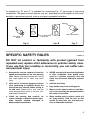
1
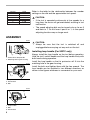
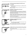
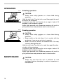
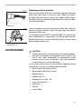
Electronic Sander
Polisher
180 mm (7”)
MODEL 9227C
MODEL 9227CY
003430
I N S T R U C T I O N
M A N U A L
WARNING:
For your personal safety, READ and UNDERSTAND before using.
SAVE THESE INSTRUCTIONS FOR FUTURE REFERENCE.
w w w. m a k i t a t o o l s. c o m
SPECIFICATIONS
Model
9227C/9227CY
No load speed (RPM)
0 - 3,000/min.
Overall length
470 mm (18-1/2”)
Net weight
3.0 kg (6.6 lbs)
Spindle thread
5/8” - 11UNC
• Manufacturer reserves the right to change specifications without notice.
• Specifications may differ from country to country.
GENERAL SAFETY RULES
USA001-2
(For All Tools)
WARNING:
Read and understand all instructions. Failure to follow all
instructions listed below, may result in electric shock, fire and/or
serious personal injury.
SAVE THESE INSTRUCTIONS
Work Area
Electrical Safety
1. Keep your work area clean and well lit.
Cluttered benches and dark areas invite accidents.
4. Grounded tools must be plugged into an
outlet properly installed and grounded in
accordance with all codes and ordinances. Never remove the grounding
prong or modify the plug in any way. Do
not use any adaptor plugs. Check with a
qualified electrician if you are in doubt as
to whether the outlet is properly
grounded. If the tools should electrically malfunction or break down, grounding provides a
low resistance path to carry electricity away
from the user.
2. Do not operate power tools in explosive
atmospheres, such as in the presence of
flammable liquids, gases, or dust. Power
tools create sparks which may ignite the dust
or fumes.
3. Keep bystanders, children, and visitors
away while operating a power tool. Distractions can cause you to lose control.
2
5. Avoid body contact with grounded surfaces such as pipes, radiators, ranges and
refrigerators. There is an increased risk of
electric shock if your body is grounded.
6. Do not expose power tools to rain or wet
conditions. Water entering a power tool will
increase the risk of electric shock.
7. Do not abuse the cord. Never use the cord
to carry the tools or pull the plug from an
outlet. Keep cord away from heat, oil,
sharp edges or moving parts. Replace
damaged cords immediately. Damaged
cords increase the risk of electric shock.
8. When operating a power tool outside, use
an outdoor extension cord marked “W-A”
or “W”. These cords are rated for outdoor
use and reduce the risk of electric shock.
Personal Safety
9. Stay alert, watch what you are doing and
use common sense when operating a
power tool. Do not use tool while tired or
under the influence of drugs, alcohol, or
medication. A moment of inattention while
operating power tools may result in serious
personal injury.
10. Dress properly. Do not wear loose clothing or jewelry. Contain long hair. Keep
your hair, clothing, and gloves away from
moving parts. Loose clothes, jewelry, or long
hair can be caught in moving parts.
11. Avoid accidental starting. Be sure switch
is off before plugging in. Carrying tools with
your finger on the switch or plugging in tools
that have the switch on invites accidents.
12. Remove adjusting keys or wrenches
before turning the tool on. A wrench or a
key that is left attached to a rotating part of
the tool may result in personal injury.
13. Do not overreach. Keep proper footing
and balance at all times. Proper footing and
balance enables better control of the tool in
unexpected situations.
14. Use safety equipment. Always wear eye
protection. Dust mask, non-skid safety
shoes, hard hat, or hearing protection must
be used for appropriate conditions. Ordinary
eye or sun glasses are NOT eye protection.
Tool Use and Care
15. Use clamps or other practical way to
secure and support the workpiece to a
stable platform. Holding the work by hand or
against your body is unstable and may lead
to loss of control.
16. Do not force tool. Use the correct tool for
your application. The correct tool will do the
job better and safer at the rate for which it is
designed.
17. Do not use tool if switch does not turn it
on or off. Any tool that cannot be controlled
with the switch is dangerous and must be
repaired.
18. Disconnect the plug from the power
source before making any adjustments,
changing accessories, or storing the tool.
Such preventive safety measures reduce the
risk of starting the tool accidentally.
19. Store idle tools out of reach of children
and other untrained persons. Tools are
dangerous in the hands of untrained users.
20. Maintain tools with care. Keep cutting
tools sharp and clean. Properly maintained
tools with sharp cutting edges are less likely
to bind and are easier to control.
21. Check for misalignment or binding of
moving parts, breakage of parts, and any
other condition that may affect the tools
operation. If damaged, have the tool serviced before using. Many accidents are
caused by poorly maintained tools.
22. Use only accessories that are recommended by the manufacturer for your
model. Accessories that may be suitable for
one tool, may become hazardous when used
on another tool.
3
SERVICE
23. Tool service must be performed only by
qualified repair personnel. Service or maintenance performed by unqualified personnel
could result in a risk of injury.
24. When servicing a tool, use only identical
replacement parts. Follow instructions in
the Maintenance section of this manual.
Use of unauthorized parts or failure to follow
Maintenance instructions may create a risk of
electric shock or injury.
USE PROPER EXTENSION CORD: Use only three-wire extension cords that have threeprong grounding-type plugs and three-pole receptacles that accept the tool's plug. Make
sure your extension cord is in good condition. Replace or repair damaged or worn cord
immediately. When using an extension cord, be sure to use one heavy enough to carry the
current your product will draw. An undersized cord will cause a drop in line voltage resulting
in loss of power and overheating. Table 1 shows the correct size to use depending on cord
length and nameplate ampere rating. If in doubt, use the next heavier gage. The smaller the
gage number, the heavier the cord.
Table 1: Minimum gage for cord
Volts
120 V
Ampere Rating
More Than
Not More Than
0
6
10
12
6
10
12
16
25 ft.
Total length of cord in feet
50 ft.
100 ft.
150 ft.
AWG
18
18
16
14
16
16
16
12
16
14
14
12
14
12
Not Recommended
GROUNDING INSTRUCTIONS
This tool should be grounded while in use to protect the operator from electric shock. The
tool is equipped with a three-conductor cord and three-prong grounding type plug to fit the
proper grounding type receptacle. The green (or green and yellow) conductor in the cord is
the grounding wire. Never connect the green (or green and yellow) wire to a live terminal.
Your unit is for use on 120 volts and has a plug that looks like Fig. “A”.
4
An adapter Fig. “B” and “C” is available for connecting Fig. “A” type plugs to two-prong
receptacles. The green-colored rigid ear, lug, etc., extending from the adapter must be connected to a permanent ground, such as a properly grounded outlet box.
Adapter
Grounding Means
Cover of Grounded
Outlet Box
Grounding
Blade
Fig. A
Fig. B
SPECIFIC SAFETY RULES
Fig. C
USB047-3
DO NOT let comfort or familiarity with product (gained from
repeated use) replace strict adherence to polisher safety rules.
If you use this tool unsafely or incorrectly, you can suffer serious personal injury.
1. Accessories must be rated for at least the
speed recommended on the tool warning
label. Wheels and other accessories running
over rated speed can fly apart and cause
injury.
4. NEVER use tool with wood cutting blades
or other sawblades. Such blades when
used on a polisher frequently kick and
cause loss of control leading to personal
injury.
2. Hold tool by insulated gripping surfaces
when performing an operation where the
cutting tool may contact hidden wiring or
its own cord. Contact with a “live” wire will
make exposed metal parts of the tool “live”
and shock the operator.
5. Hold the tool firmly.
3. Check the backing pad carefully for
cracks, damage or deformity before operation. Replace cracked, damaged or
deformed pad immediately.
8. When sanding metal surfaces, watch out
for flying sparks. Hold the tool so that
sparks fly away from you and other persons or flammable materials.
6. Keep hands away from rotating parts.
7. Make sure the abrasive disc or wool bonnet is not contacting the workpiece before
the switch is turned on.
5
9. Do not leave the tool running. Operate the
tool only when hand-held.
10. Do not touch the workpiece immediately
after operation; it may be extremely hot
and could burn your skin.
11. Check that the workpiece is properly supported.
12. Pay attention that the wheel continues to
rotate after the tool is switched off.
13. This tool has not been waterproofed, so
do not use water on the workpiece surface.
14. Ventilate your work area adequately when
you perform sanding operations.
15. Use of this tool to sand some products,
paints and wood could expose user to
dust containing hazardous substances.
Use appropriate respiratory protection.
SAVE THESE INSTRUCTIONS
WARNING:
MISUSE or failure to follow the safety rules stated in this
instruction manual may cause serious personal injury.
SYMBOLS
USD101-2
The followings show the symbols used for tool.
V ....................... volts
................alternating current
A ....................... amperes
n ....................no load speed
˚
Hz ..................... hertz
.../min................revolutions or reciprocation per
minute
6
FUNCTIONAL
DESCRIPTION
•
003432
CAUTION:
Always be sure that the tool is switched off and
unplugged before adjusting or checking function on the
tool.
Shaft lock
1
•
CAUTION:
Never actuate the shaft lock when the spindle is moving.
The tool may be damaged.
Press the shaft lock to prevent spindle rotation when installing or removing accessories.
1. Shaft lock
003435
Switch action
1
•
•
2
1. Lock button
2. Switch trigger
CAUTION:
Before plugging in the tool, always check to see that the
switch trigger actuates properly and returns to the “OFF”
position when released.
Switch can be locked in “ON” position for ease of
operator comfort during extended use. Apply caution
when locking tool in “ON” position and maintain firm
grasp on tool.
To start the tool, simply pull the switch trigger. Tool speed is
increased by increasing pressure on the switch trigger.
Release the switch trigger to stop.
For continuous operation, pull the switch trigger and then
push in the lock button.
To stop the tool from the locked position, pull the switch trigger fully, then release it.
003440
1
Speed adjusting dial
The tool speed can be changed by turning the speed adjusting dial to a given number setting from 1 to 6. (At the time
when the switch trigger is fully pulled.)
Higher speed is obtained when the dial is turned in the direction of number 6. And lower speed is obtained when it is
turned in the direction of number 1.
1. Speed adjusting dial
7
Number
1
2
3
4
5
6
Refer to the table for the relationship between the number
settings on the dial and the approximate tool speed.
RPM
600
900
1,500
2,100
2,700
3,000
•
•
CAUTION:
If the tool is operated continuously at low speeds for a
long time, the motor will get overloaded, resulting in tool
malfunction.
The speed adjusting dial can be turned only as far as 6
and back to 1. Do not force it past 6 or 1, or the speed
adjusting function may no longer work.
ASSEMBLY
003448
•
CAUTION:
Always be sure that the tool is switched off and
unplugged before carrying out any work on the tool.
Installing loop handle (For 9227C only)
1
2
1. Protrusion of loop handle
2. Matching hole in gear housing
003449
Install the bolts and tighten them with the hex wrench. The
loop handle can be installed in two different directions as
shown in the figures whichever is convenient for your work.
1
2
3
1. Loop handle
2. Hex wrench
3. Bolt
003450
1
2
1. Loop handle
2. Bolt
3. Hex wrench
8
Always install the loop handle on the tool before operation.
Hold the tool’s switch handle and the loop handle firmly with
both hands during operation.
Install the loop handle so that its protrusion will fit into the
matching hole in the gear housing.
3
003805
Installing side grip (handlle) (For 9227CY only)
•
CAUTION:
Always be sure that the side grip is installed securely
before operation.
Screw the side grip securely on the position of the tool as
shown in the figure.
003467
1
To install the wool bonnet, first remove all dirt or foreign matter from the backing pad. Press the shaft lock and screw the
backing pad onto the spindle. Insert the sleeve 18 into the
center hole of the backing pad.
2
3
4
5
1.
2.
3.
4.
5.
Installing or removing the wool bonnet
(optional accessory)
Using the sleeve 18 as a positioning guide, install the wool
bonnet on the backing pad with the sleeve 18 inserted
through the center hole of the wool bonnet. Then remove the
sleeve 18 from the backing pad.
Wool bonnet
Sleeve 18
Backing pad
Spindle
Shaft lock
To remove the wool bonnet, just tear it off the backing pad.
Then unscrew the backing pad while pressing the shaft lock.
003457
1
Installing or removing abrasive disc
(optional accessory)
2
NOTE:
3
•
4
1.
2.
3.
4.
Mount the rubber pad onto the spindle. Fit the abrasive disc
on the rubber pad and screw the lock nut onto the spindle.
Lock nut
Abrasive disc
Rubber pad
Spindle
003458
1
Use sander accessories specified in this manual. These
must be purchased separately.
To tighten the lock nut, press the shaft lock firmly so that the
spindle cannot revolve, then use the lock nut wrench and
securely tighten clockwise.
To remove the disc, follow the installation procedure in
reverse.
2
1. Lock nut wrench
2. Shaft lock
9
OPERATION
003478
Polishing operation
•
CAUTION:
Always wear safety glasses or a face shield during
operation.
Hold the tool firmly. Turn the tool on and then apply the wool
bonnet to the workpiece.
In general, keep the wool bonnet at an angle of about 15
degrees to the workpiece surface.
Apply slight pressure only. Excessive pressure will result in
poor performance and premature wear to wool bonnet.
003473
Sanding operation
•
CAUTION:
Always wear safety goggles or a face shield during
operation.
•
Never switch on the tool when it is in contact with the
workpiece, it may cause an injury to operator.
•
Never run the tool without the abrasive disc. You may
seriously damage the pad.
Hold the tool firmly. Turn the tool on and then apply the abrasive disc to the workpiece.
In general, keep the abrasive disc at an angle of about 15
degrees to the workpiece surface.
Apply slight pressure only. Excessive pressure will result in
poor performance and premature wear to abrasive disc.
MAINTENANCE
•
10
CAUTION:
Always be sure that the tool is switched off and
unplugged before attempting to perform inspection or
maintenance.
001145
Replacing carbon brushes
Remove and check the carbon brushes regularly. Replace
when they wear down to the limit mark. Keep the carbon
brushes clean and free to slip in the holders. Both carbon
brushes should be replaced at the same time. Use only identical carbon brushes.
1
1. Limit mark
003483
1
1. Screwdriver
2. Brush holder cap
2
Use a screwdriver to remove the brush holder caps. Take out
the worn carbon brushes, insert the new ones and secure
the brush holder caps.
To maintain product SAFETY and RELIABILITY, repairs, any
other maintenance or adjustment should be performed by
Makita Authorized or Factory Service Centers, always using
Makita replacement parts.
ACCESSORIES
•
CAUTION:
These accessories or attachments are recommended for
use with your Makita tool specified in this manual. The
use of any other accessories or attachments might
present a risk of injury to persons. Only use accessory
or attachment for its stated purpose.
If you need any assistance for more details regarding these
accessories, ask your local Makita service center.
•
Wool bonnet 180 (Hook & loop)
•
Backing pad 165 (Hook & loop)
•
Abrasive discs
•
Rubber pad 170
•
Sanding lock nut 5/8 - 48
•
Lock nut wrench 28
•
Sleeve 18
•
Grip 36
•
Loop handle
11
Memo
12
Cut
First-Class
Postage
Required
Post Office will
not deliver
without proper
postage.
Makita U.S.A., Inc.
14930 Northam Street
La Mirada, CA 90638-5753
Fold
13
MAIL THIS PORTION
Your answers to the following questions are appreciated.
1. This product was purchased from:
Home Center
3. How did you learn about this product:
Magazine
Radio
Hardware/Lumber Store
From Dealer
Exhibition
Tool Distributor
Newspaper
From Friend
Industrial Supply
Store Display
Previous Usage
Construction Supply
Catalog
Other (
Other (
)
2. Use of the product is intended for:
)
4. Most favored points are:
Construction Trade
Design
Repair Service
Industrial Maintenance
Features
Durability
Home Maintenance
Size
Power
Hobby
Price
Other (
Other (
)
)
Makita Brand
5. Any comments:
Paste
MODEL NO.
DAY
YEAR
SERIAL NO.
SEX
STATUS
INTL.
LAST NAME / COMPANY NAME
Married Single
M
F
STREET ADRESS
Paste
MONTH
Paste
Paste
Paste
Paste
DATE PURCHASED
Under 19
AREA
CODE
PHONE
20-29
30-39
Paste
AGE:
ZIP CODE
40-49
50-60
Over 60
Paste
Paste
STATE
Paste
CITY
Paste
Paste
BE SURE TO COMPLETE THE CUSTOMER’S PORTION OF THIS FORM AND RETAIN FOR YOUR RECORDS.
Please return this portion by facsimile or mail.
14
Facsimile No: (714) 522-8133
Paste
Paste
Paste
Paste
Paste
Paste
Paste
Paste
FACTORY SERVICE CENTERS
1-800-4-MAKITA
RETAIN THIS PORTION FOR YOUR RECORDS
ARIZONA
3707 E. Broadway Rd., Ste. 6
Phoenix, AZ 85040
(602) 437-2850
FLORIDA
750 East Sample Road
Pompano Beach, FL 33064
(954) 781-6333
MISSOURI
9876 Watson Road
St. Louis, MO 63126-2221
(314) 909-9889
PENNSYLVANIA
1704 Babcock Blvd.
Pittsburgh, PA 15209
(412) 822-7370
CALIFORNIA
41850 Christy St.
Fremont, CA 94538-5107
(510) 657-9881
GEORGIA
4680 River Green Parkway NW
Duluth, GA 30096
(770) 476-8911
NEBRASKA
4129 S. 84th St.
Omaha, NE 68127
(402) 597-2925
PUERTO RICO
200 Guayama St.
Hato Rey, PR 00917
(787) 250-8776
ILLINOIS
1450 Feehanville Dr.
Mt. Prospect, IL 60056-6011
(847) 297-3100
NEVADA
3375 S. Decatur Blvd.
Suites. 22 - 24
Las Vegas, NV 89102
(702) 368-4277
TENNESSEE
1120 Elm Hill P.
Suile 170 Nashville, TN 372
(615) 248-3321
14930 Northam St.
La Mirada, CA 90638-5753
(714) 522-8088
1970 Fulton Avenue
Sacramento, CA 95825
(916) 482-5197
7674 Clairemont Mesa Blvd.
San Diego, CA 92111
(858) 278-4471
16735 Saticoy St., Ste. 105
Van Nuys, CA 91406
(818) 782-2440
COLORADO
11839 E. 51st Ave.
Denver, CO 80239-2709
(303) 371-2850
MARYLAND
7397 Washington Boulevard,
Suite 104 Elkridge, MD 21075
(410) 796-4401
MASSACHUSETTS
232 Providence Hwy.
Westwood, MA 02090
(781) 461-9754
MINNESOTA
6427 Penn Ave. South
Richfield, MN 55423
(612) 869-5199
NEW JERSEY
251 Herrod Blvd.
Dayton, NJ 08810-1539
(609) 655-1212
NEW YORK
4917 Genessee Street
Cheektowaga, NY 14225
(716) 685-9503
OREGON
828 19th Avenue, N.W.
Portland, OR 97209
(503) 222-1823
TEXAS
12801 Stemmons Fwy Ste. 809
Farmers Branch, TX 75234
(972) 243-1150
12701 Directors Dr.
Stafford, TX 77477-3701
(281) 565-8665
3453 IH-35 North, Ste. 101
San Antonio, TX 78219
(210) 228-0676
WISCONSIN
Lincoln Plaza Shopping Ctr.
2245 S. 108th St. West Allis, WI
53227
(414) 541-4776
CUSTOMER’S RECORD
When you need service: Send
complete tool (prepaid) to one
of the Makita Factory Service
Centers listed, or to an Authorized
Makita Service Center. Be sure
to attach a letter to the outside of
the carton detailing the problem
with your tool.
Date Purchased
Dealer’s Name & Address
Model No.
Serial No.
15
WARNING
Some dust created by power sanding, sawing, grinding, drilling, and other
construction activities contains chemicals known to the State of California
to cause cancer, birth defects or other reproductive harm. Some examples
of these chemicals are:
• lead from lead-based paints,
• crystalline silica from bricks and cement and other masonry products, and
• arsenic and chromium from chemically-treated lumber.
Your risk from these exposures varies, depending on how often you do this
type of work. To reduce your exposure to these chemicals: work in a well
ventilated area, and work with approved safety equipment, such as those
dust masks that are specially designed to filter out microscopic particles.
MAKITA LIMITED ONE YEAR WARRANTY
Warranty Policy
Every Makita tool is thoroughly inspected and tested before leaving the factory. It is warranted to be free of
defects from workmanship and materials for the period of ONE YEAR from the date of original purchase.
Should any trouble develop during this one year period, return the COMPLETE tool, freight prepaid, to one of
Makita’s Factory or Authorized Service Centers. If inspection shows the trouble is caused by defective
workmanship or material, Makita will repair (or at our option, replace) without charge.
This Warranty does not apply where:
• repairs have been made or attempted by others:
• repairs are required because of normal wear and tear:
• the tool has been abused, misused or improperly maintained:
• alterations have been made to the tool.
IN NO EVENT SHALL MAKITA BE LIABLE FOR ANY INDIRECT, INCIDENTAL OR CONSEQUENTIAL
DAMAGES FROM THE SALE OR USE OF THE PRODUCT. THIS DISCLAIMER APPLIES BOTH DURING
AND AFTER THE TERM OF THIS WARRANTY.
MAKITA DISCLAIMS LIABILITY FOR ANY IMPLIED WARRANTIES, INCLUDING IMPLIED WARRANTIES OF
“MERCHANTABILITY” AND “FITNESS FOR A SPECIFIC PURPOSE,” AFTER THE ONE YEAR TERM OF THIS
WARRANTY.
This Warranty gives you specific legal rights, and you may also have other rights which vary from state to state.
Some states do not allow the exclusion or limitation of incidental or consequential damages, so the above
limitation or exclusion may not apply to you. Some states do not allow limitation on how long an implied
warranty lasts, so the above limitation may not apply to you.
Makita Corporation
3-11-8, Sumiyoshi-cho,
Anjo, Aichi 446-8502 Japan
884103E068