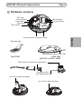
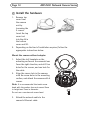
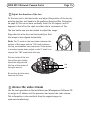
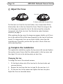
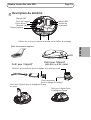
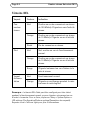
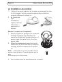
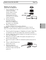
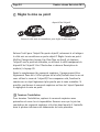
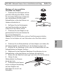
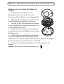
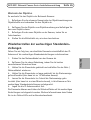
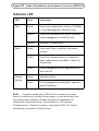
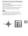
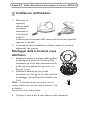
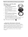
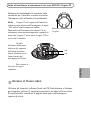
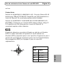
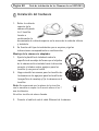
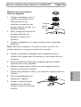
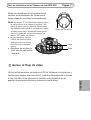
1
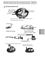
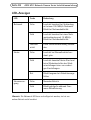
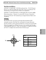
INSTALLATION GUIDE AXIS M31 Network Camera Series ENGLISH AXIS M3113-R Network Camera AXIS M3113-R M12 Network Camera AXIS M3114-R M12 Network Camera DEUTSCH AXIS M3114-R M12 2MM Network Camera FRANÇAIS AXIS M3114-R Network Camera ITALIANO ESPAÑOL About this Document This document includes instructions for installing AXIS M31 Network Camera Series on your network. Previous experience of networking will be beneficial when installing the product. Legal Considerations surveillance can be prohibited by laws that vary from country to country. Check the laws in your local region before using this product for surveillance purposes. This product includes one (1) H.264 decoder license. To purchase further licenses, contact your reseller. Trademark Acknowledgments Apple, Boa, Bonjour, Ethernet, Internet Explorer, Linux, Microsoft, Mozilla, Real, SMPTE, QuickTime, UNIX, Windows, Windows Vista and WWW are registered trademarks of the respective holders. Java and all Javabased trademarks and logos are trademarks or registered trademarks of Oracle and/or its affiliates. UPnPTM is a certification mark of the UPnPTM Implementers Corporation. Electromagnetic Compatibility (EMC) This equipment has been designed and tested to fulfill applicable standards for: • Radio frequency emission when installed according to the instructions and used in its intended environment. • Immunity to electrical and electromagnetic phenomena when installed according to the instructions and used in its intended environment. USA - This equipment has been tested using a shielded network cable (STP) and found to comply with the limits for a Class B digital device, pursuant to part 15 of the FCC Rules. These limits are designed to provide reasonable protection against harmful interference in a residential installation. This equipment generates, uses and can radiate radio frequency energy and, if not installed and used in accordance with the instructions, may cause harmful interference to radio communications. However, there is no guarantee that interference will not occur in a particular installation. If this equipment does cause harmful interference to radio or television reception, which can be determined by turning the equipment off and on, the user is encouraged to try to correct the interference by one or more of the following measures: • Reorient or relocate the receiving antenna. • Increase the separation between the equipment and receiver. • Connect the equipment into an outlet on a circuit different from that to which the receiver is connected. • Consult the dealer or an experienced radio/TV technician for help. Canada - This Class B digital apparatus complies with Canadian ICES-003. Europe This digital equipment fulfills the requirements for RF emission according to the Class B limit of EN 55022. This product fulfills the requirements for immunity according to EN 610006-1 residential, commercial and lightindustrial environments. This product fulfills the requirements for immunity according to EN 610006-2 industrial environments. This product fulfills the requirements for immunity according to EN 55024 residential and commercial environments. Australia This digital equipment fulfills the requirements for RF emission according to the Class B limit of AS/ NZS CISPR 22. Japan - この装置は、クラスB 情報技術装置です。 この装置は、家庭環境で使用することを目 的として いますが、この装置がラジオやテレビジョン受信機 に近接して使用されると、 受信障害を引き起こすこ とがあります。 取扱説明書に従って正しい取り扱い をして下さい。 Korea - ࢇ̛̛Еɼࢽࡈ%̗ࢷળࢶଢ̛̛Ի۰ ࣯Իɼࢽ߾۰ࡈیଜЕʨࡶּࢶࡳԻଜֲֻҘ एࠇ߾۰ࡈیଟܹݡТЬ Safety This product complies with IEC/EN 60950-1, Safety of Information Technology Equipment. The power supply used with this product shall fulfill the requirements for Safety Extra Low Voltage (SELV) and Limited Power Source (LPS) according to EN/IEC/UL 60950-1. Equipment Modifications This equipment must be installed and used in strict accordance with the instructions given in the user documentation. This equipment contains no user-serviceable components. Unauthorized equipment changes or modifications will invalidate all applicable regulatory certifications and approvals. Liability Every care has been taken in the preparation of this document. Please inform your local Axis office of any inaccuracies or omissions. Axis Communications AB cannot be held responsible for any technical or typographical errors and reserves the right to make changes to the product and documentation without prior notice. Axis Communications AB makes no warranty of any kind with regard to the material contained within this document, including, but not limited to, the implied warranties of merchantability and fitness for a particular purpose. Axis Communications AB shall not be liable nor responsible for incidental or consequential damages in connection with the furnishing, performance or use of this material. This product is only to be used for its intended purpose. RoHS This product complies with both the European RoHS directive, 2002/95/EC, and the Chinese RoHS regulations, ACPEIP. WEEE Directive The European Union has enacted a Directive 2002/96/ EC on Waste Electrical and Electronic Equipment (WEEE Directive). This directive is applicable in the European Union member states. The WEEE marking on this product (see right) or its documentation indicates that the product must not be disposed of together with household waste. To prevent possible harm to human health and/or the environment, the product must be disposed of in an approved and environmentally safe recycling process. For further information on how to dispose of this product correctly, contact the product supplier, or the local authority responsible for waste disposal in your area. Business users should contact the product supplier for information on how to dispose of this product correctly. This product should not be mixed with other commercial waste. Support Should you require any technical assistance, please contact your Axis reseller. If your questions cannot be answered immediately, your reseller will forward your queries through the appropriate channels to ensure a rapid response. If you are connected to the Internet, you can: • download user documentation and firmware updates • find answers to resolved problems in the FAQ database. Search by product, category, or phrases • report problems to Axis support by logging in to your private support area. • chat with Axis support staff (selected countries only) • visit Axis Support at www.axis.com/ techsup/ Safeguards Please read through this Installation Guide carefully before installing the Axis product. Keep the Installation Guide for further reference. ENGLISH • Store the Axis product in a dry and ventilated environment. • Only use applicable tools when installing the Axis product; excessive force could cause damage to the product. • Do not use chemicals, caustic agents, or aerosol cleaners. Use a damp cloth for cleaning. • Use only accessories that comply with technical specification of the product. These can be provided by Axis or a third party. • Use only spare parts provided by or recommended by Axis. • Do not attempt to repair the product by yourself, contact Axis or your Axis reseller for service matters. • This Axis product shall be used in compliance with local laws and regulations. • To use this Axis product outdoors, it shall be installed in an approved outdoor housing. • The Axis product should be installed by a trained professional. Observe relevant national and local regulations for the installation. • If the installation requires IP66/IP67 classification, the attached network cable and IP66/IP67 classified network connector must be used to create a waterproof seal. • The product is designed for installation in vehicles. Mount the product on the ceiling or wall. • For proper protection from water ingress: • The top cover shall be properly closed. • The camera shall not be mounted outdoors facing the sky where the screws can collect water. • When mounted on a wall, the cable shall not go downwards into the camera, which can cause water to enter the camera. It is recommended that the cables go down from the camera or sideways. • Do not bend the network cable too close to the camera. Transportation • When transporting the Axis product, use the original packaging or equivalent to prevent damage to the product. AXIS M31 Network Camera Series Page 7 AXIS M31-R Series Installation Guide This installation guide provides instructions for installing the following network cameras: Installation steps 1. 2. 3. 4. 5. 6. Important! Check the package This product must be used in contents against the compliance with local laws and list below. regulations. Hardware overview. See page 9. Install the hardware. See page 12. Access the video stream. See page 15 Adjust the focus. See page 16. Complete the installation. See page 16. ENGLISH • AXIS M3113-R • AXIS M3113-R M12 • AXIS M3114-R • AXIS M3114-R M12 • AXIS M3114-R M12 2MM For all other aspects of using the product, please see the user manual, available from www.axis.com/techsup Page 8 AXIS M31 Network Camera Series Package contents Item Models/variants/notes Network camera AXIS M3113-R, AXIS M3113-R M12 AXIS M3114-R, AXIS M3114-R M12 AXIS M3114-R M12 2MM Tools Lens tool, Allen key, Top cover tool, Drill template Optional accessories Adaptor for flat surface with 4 screws Adaptor for curved surface CD Installation and Management Software CD Printed Materials AXIS Product Installation Guide (this document) Extra serial number labels (2x) AVHS Authentication key Drill template AXIS M31 Network Camera Series Page 9 Hardware overview 180° mark (top of image) Lens holder Optic mount Optic holder LED indicators Control button ENGLISH Use screws here to mount camera Top cover tool Netzwerkkabel cable (0.5m/1.6ft.) Lens tool Lens tool (AXIS M3114-R M12 2MM) Black rubber side (for focus adjustment) Transparent side (for image adjustment) Lens tool for adjusting image Lens tool for adjusting focus Page 10 AXIS M31 Network Camera Series LED indicators LED Color Indication Network Green Steady for connection to a 100 Mbit/s network. Flashes for network activity. Amber Steady for connection to 10 Mbit/s network. Flashes for network activity. Unlit No network connection. Green Steady green for normal operation. Amber Steady during startup, during reset to factory default or when restoring settings. Red Slow flash for failed upgrade. Green Normal operation. Amber Flashes green/amber during firmware upgrade. Status Power Note: The Network and Status LEDs can be configured to be unlit during normal operation from Setup > System Options > LED settings; and the Status LED can also be configured to flash only when the camera is accessed. See online help files for more information. AXIS M31 Network Camera Series Page 11 Connectors Network connector (AXIS M3113-R/AXIS M3114-R) - Female RJ-45 Ethernet connector for 10BaseT/100BaseTX. Supports Power over Ethernet. Using shielded cables is recommended. Network connector (AXIS M3113-R M12/AXIS M3114-R M12/AXIS M3114-R M12 2MM - Rugged female, D-coded M12 connector. Supports Power over Ethernet. Using shielded cables is recommended. RX+ TX+ M12 TX- RX- Data Power TX+ DC+/DC- RX+ DC-/DC+ TX- DC+/DC- RX- DC-/DC+ ENGLISH The product shall be connected using a shielded network cable (STP). All cables connecting the product to the midspan shall be shielded (STP) and intended for their specific use. Make sure the network switch is properly grounded. See Electromagnetic Compatibility (EMC) for regulatory requirements on page 2. Page 12 AXIS M31 Network Camera Series Install the hardware 1. 2. Remove top cover from the camera unit by loosening the 2 screws. Insert the top cover tool into the slit in the bottom cover and lift. Depending on the kind of installation required, follow the appropriate instructions below. Mount the camera without adaptor 1. Adjust the drill template on the mounting surface so the camera’s lens faces the right direction, and drill four holes for the screws, and one hole for the cable. 2. Align the screw slots in the camera with the screw holes in the mounting surface, and attach the camera with 4 screws. Note: It is recommended that each screw head with the washer does not exceed 5mm in height and 7mm in diameter. Do not use a countersunk screw head. 3. Attach the network cable to the camera’s Ethernet cable. AXIS M31 Network Camera Series Page 13 Mount on a curved surface with an adaptor 1. tabs do not stick to the surface material. 4. 5. 6. 7. 8. 9. Place the drill template on the adaptor and turn the camera lens in the direction you want the camera to point. Adjust template to align screw holes with the adaptor’s screw holes. Mark the cable hole, and mark the four screw holes if drilling is required. Drill the cable hole, and if required, 4 holes for the screws. Route the camera’s Ethernet cable through the hole. Place the camera on the adaptor in the right direction and fasten with four screws. ENGLISH Place the adaptor on the curved mounting surface, align the two curvatures, and mark the two screw adaptor holes if drilling is required. adhesive tab 2. Remove protective paper from the adhesive tabs on the adaptor by pulling the ends. curved surface 3. Place the adaptor in position and press down on the adhesive tabs. Note: Fasten the adaptor to the surface with two screws if the adhesive Page 14 AXIS M31 Network Camera Series Mount on a flat surface with an adaptor 1. Place the adaptor on the mounting surface and position the slot for the cable where appropriate. 2. Fasten the adaptor with three screws appropriate to the surface material. 3. Fix the camera’s Ethernet cable in the slot in the adaptor and press into place. 4. Place the camera on the adaptor, and turn the camera so the lens faces the correct direction. 5. Adjust so the screw slots on the camera are aligned with the screw holes in the adaptor, and attach the 4 screws (torque < 2.5 Nm). 6. Attach the network cable to the camera’s Ethernet cable. Note: Do not use a countersunk screw head. AXIS M31 Network Camera Series Page 15 Adjust the direction of the lens Fit the lens tool to the lens holder, and adjust the position of the lens by pointing the lens tool handle in the preferred direction (See illustration on page 6). This can be done vertically from 0 to 90 degrees, and 30 degrees to the left or the right on either side in increments of five. The lens holder can also be rotated to adjust the image. Align the ribs in the lens tool horizontally so that the image is also aligned horizontally. The line inside of the bottom of the optic holder should be aligned with the line at the center of the optic mount. Align ribs horizontally line line Do not turn the lens more than one full turn. Access the video stream Use the tools provided on the Installation and Management Software CD to assign an IP address, set the password and access the video stream. This information is also available from the support pages on www.axis.com/techsup ENGLISH Note: The '0' mark on the lens holder indicates the bottom of the image and the ‘180’ mark indicates the top, see Hardware overview above. If the camera is mounted upside down, adjust so the '0' mark is on top and the '180' mark below the lens. Page 16 AXIS M31 Network Camera Series Adjust the focus lens tool Fit black rubber side to adjust focus Pull the lens tool from the lens tool holder, turn it around and fit the black rubber side to the lens. Adjust the focus. Check the image in the Live View page, and move the lens to the desired position using the transparent side of the lens tool. See illustration under Hardware overview, on page 6. After replacing the top cover, the image may appear slightly out of focus due to the optical effect of the dome (especially in the case of tele/zoom lenses). To compensate, focus on an object slightly closer than the intended area. If possible, position the top cover in front of the lens while adjusting focus. Complete the installation To complete the installation, replace the top cover with care and tighten the captive screws. Ensure that the rubber gasket in the top cover, and the ridge it fits into in the bottom plate, are dust-free. Changing the lens To change the lens of the network camera: 1. Fit the black rubber side of the lens tool to the lens holder and unscrew the lens. 2. Remove the lens from the lens tool and fix the new lens to it. 3. Fit the new lens to the camera and tighten the lens into place. Adjust the focus as described above. AXIS M31 Network Camera Series Page 17 Resetting to the Factory Default Settings This will reset all parameters, including the IP address, to the Factory Default settings: 1. 2. 3. Further Information The User Manual is available from the Axis Web site at www.axis.com Visit Axis learning center www.axis.com/academy for useful trainings, webinars, tutorials and guides. Tip! Visit www.axis.com/techsup to check if there is updated firmware available for your network product. To see the currently installed firmware version, see Setup > About. Warranty For information about Axis’ product warranty and thereto related information, see www.axis.com/warranty ENGLISH Disconnect the network cable from the camera. Remove the top cover by loosening the 2 captive screws. Press and hold the Control button and reconnect the power\network cable. 4. Keep the Control button pressed until the Status indicator displays amber (this may take up to 15 seconds). 5. Release the Control button. When the Status indicator displays green (which can take up to 1 minute) the process is complete and the camera has been reset. 6. Re-assign the IP address. It is also possible to reset parameters to the original factory default settings via the web interface. For more information, please see the online help or the user’s manual. Mesures de sécurité Lisez attentivement le présent Guide d'installation avant d'installer le produit Axis. Conservez le Guide d'installation pour une utilisation ultérieure. FRANÇAIS • Conservez le produit Axis dans un environnement sec et aéré. • N'utilisez que les outils applicables pour installer le produit Axis ; une force excessive pourrait endommager le produit. • Pour le nettoyage, n’utilisez ni produits chimiques, ni substances caustiques ou aérosols. Utilisez un chiffon humide pour le nettoyage. • N’utilisez que des accessoires conformes aux caractéristiques techniques du produit. Ceux-ci peuvent être fournis par Axis ou par un fournisseur tiers. • Utilisez uniquement des pièces de rechange fournies ou recommandées par Axis. • Ne tentez pas de réparer le produit vous-même, contactez Axis ou votre revendeur Axis pour toute réparation. • Ce produit Axis doit être utilisé conformément aux lois et réglementations locales en vigueur. • Pour pouvoir être utilisé à l'extérieur, ce produit Axis doit être placé dans un boîtier d'extérieur homologué. • Le produit Axis doit être installé par un professionnel qualifié. Veuillez vous conformer aux règlements nationaux et locaux relatifs à l'installation. • Si l'installation requiert une classification IP66/IP67, le câble réseau et le connecteur réseau classifié IP66/IP67 fournis doivent être utilisés pour créer un joint étanche à l'eau. • Le produit est conçu pour être installé dans les véhicules. Montez l'appareil sur le mur ou au plafond. • Pour une bonne protection contre les infiltrations d'eau: • Le capot supérieur doit être correctement fermé. • La caméra ne doit pas être installée à l'extérieur face au ciel où les vis peuvent collecter de l'eau. • Lorsqu'elle est monté sur un mur, le câble ne doit pas être orienté vers le haut dans le support de fixation ce qui peut provoquer une infiltration d'eau dans la caméra. Il est recommandé que le câble descende du support ou sur le côté. • Ne pliez pas le câble réseau trop près de la caméra. Transport • Pour transporter le produit Axis et éviter de l'endommager, utilisez l'emballage d'origine ou un emballage équivalent. Caméra réseau Axis série M31 Page 21 Série AXIS M31Guide d’installation Ce guide d’installation vous explique comment installer les caméras réseau suivantes : • AXIS M3113-R • AXIS M3113-R M12 • AXIS M3114-R • AXIS M3114-R M12 • AXIS M3114-R M12 2MM Pour toute autre question concernant l’utilisation du produit, reportezvous au manuel de l’utilisateur, que vous trouverez sur le CD ci-joint ou sur le site www.axis.com/techsup 1. 2. 3. 4. 5. Important ! Ce produit doit être utilisé conformément aux lois et dispositions locales en vigueur. Vérification du contenu de l’emballage par rapport à la liste ci-dessous. Voir la description du matériel (page 23). Installation du matériel (page 26). Réglez la mise au point (page 30). Terminez l’installation (page 30). FRANÇAIS Procédure d’installation Page 22 Caméra réseau Axis série M31 Contenu de l’emballage Article Modèles/variantes/remarques Caméra réseau AXIS M3113-R, AXIS M3113-R M12 AXIS M3114-R, AXIS M3114-R M12 AXIS M3114-R M12 2MM Outils Outil pour l'objecif, Gabarit de perçage Clé hexagonale, Outil du couvercle supérieur. Accessoires en option Adaptateur à 4 vis pour surface plane Adaptateur pour surface courbe. CD Le CD d'installation et de gestion du logiciel, y compris les outils d'installation et autre logiciel. Documentation imprimée Guide d’installation de la Série des caméras réseau AXIS M31 (le présent document). Caméra réseau Axis série M31 Page 23 Description du matériel Marque 180 ° (haut de l’image) Porte-objectif Monture optique Support optique Témoins DEL Bouton de commande Utilisez les vis ici pour monter la caméra sur la surface de montage FRANÇAIS Outil du couvercle supérieur Câble Ethernet Outil pour l’objectif Outil pour l’objectif (AXIS M3114-R M12 2MM) Côté noir en caoutchouc (pour le réglage de la mise au point) Côté transparent (pour le réglage de l’image) Outil pour l’objectif pour le réglage de la mise au point Outil pour l’objectif pour le réglage de l’image Page 24 Caméra réseau Axis série M31 Témoins DEL Voyant Couleur Indication Connecteur réseau Vert Continu en cas de connexion à un réseau de 100 Mbits/s. Clignote en cas d’activité réseau. Orange Continu en cas de connexion à un réseau de 10 Mbits/s. Clignote en cas d’activité réseau. Éteint Pas de connexion au réseau. Vert Vert continu en cas de fonctionnement normal. Orange Continu en cas de connexion à un réseau de 10 Mbits/s. Clignote en cas d’activité réseau. Rouge Clignote lentement en cas d’échec de la mise à niveau. Vert Fonctionnement normal. Orange Clignote en vert/orange pendant la mise à niveau du micrologiciel. État Voyant d’alimentation Remarque : le témoin DEL d’état peut être configuré pour être éteint pendant le fonctionnement normal ou pour clignoter uniquement en cas d’accès à la caméra. Pour ce faire, cliquez sur Setup > System Options > LED settings (Configuration/Options système/Paramètres des voyants). Reportez-vous à l’aide en ligne pour plus d’informations. Caméra réseau Axis série M31 Page 25 Connecteurs de l’unité Connecteur réseau (AXIS M3113-R/AXIS M3114-R) - Female RJ-45 Connecteur de réseau (AXIS M3113-R/AXIS M3114-R) - Femelle RJ-45 pour 10BaseT/ 100BaseTX. Prend en charge l’alimentation par Ethernet. Il est recommandé d’utiliser des câbles blindés.. Connecteur réseau (AXIS M3113-R M12/AXIS M3114-R M12/AXIS M3114-R M12 2MM) - Connecteur femelle M12 D-codé, robuste. Prend en charge l’alimentation par Ethernet. Il est recommandé d’utiliser des câbles blindés. RX+ M12 TX+ Données Voyant d’alimentation TX+ DC+/DC- TX- RX- RX+ DC-/DC+ TX- DC+/DC- RX- DC-/DC+ FRANÇAIS Le produit doit être connecté à l'aide d'un câble réseau blindé (STP). Tous les câbles de raccordement du produit au commutateur réseau doivent être blindés (STP) et destinés à leur usage spécifique. Assurez-vous que le commutateur réseau est correctement mis à la terre. Voir la compatibilité électromagnétique (CEM) sur la page 2 pour les exigences réglementaires. Page 26 Caméra réseau Axis série M31 Installation du matériel 1. 2. Enlevez le couvercle supérieur de la caméra en desserrant les deux vis. Puis insérez l´outil du couvercle supérieur dans la fente du couvercle inférieur et soulevez-le. En fonction du type d’installation requise, suivez les instructions appropriées cidessous. Montez la caméra sans l’adaptateur 1. Ajustez le gabarit de perçage sur la surface de montage de manière que l’objectif de la caméra soit dirigé dans la bonne direction, et percez quatre trous pour les vis, et un trou pour le câble. 2. Alignez les emplacements pour les vis de la caméra avec les trous faits dans la surface de montage, et fixez la caméra avec les quatre vis. Note: Chaque tête de vis avec la rondelle devrait mesurer 5 mm de haut et 7 mm de diamètre tout au plus. N’utilisez pas de vis à tête fraisée. 3. Fixez le câble réseau au câble Ethernet de la caméra. Caméra réseau Axis série M31 Page 27 Montage sur une surface courbe avec un adaptateur 1. deux vis si les pattes adhésives n’adhèrent pas au matériau de la surface. 4. 5. 6. 7. 8. 9. Placez le gabarit de perçage sur l’adaptateur et tournez l’objectif de la caméra pour qu’elle soit orientée dans la direction souhaitée. Ajustez le gabarit de manière à aligner les trous pour les vis avec les trous dans l’adaptateur. Marquez le trou pour le câble et les quatre trous pour les vis, si percer s’avère nécessaire. Percez le trou pour le câble et, si nécessaire, quatre trous pour les vis. Insérez le câble Ethernet de la caméra dans le trou. Placez la caméra sur l’adaptateur dans la bonne direction et fixez-la à l’aide des quatre vis. FRANÇAIS Placez l’adaptateur sur une surface de montage courbe, alignez les deux adaptateur courbures et marquez l’emplacement des deux patte dhésive trous pour les vis, si percer s’avère nécessaire. surface courbe 2. Enlevez la bande de protection des pattes adhésives de l’adaptateur en tirant sur les extrémités. 3. Mettez l’adaptateur en position et appuyez sur les pattes adhésives. Remarque : Vous pourriez fixer l’adaptateur à la surface à l’aide de Page 28 Caméra réseau Axis série M31 Montage sur une surface plane avec un adaptateur 1. Placez l’adaptateur sur la surface de montage et positionnez la fente pour le câble à l’endroit approprié. 2. Fixez l’adaptateur avec trois vis qui sont appropriées au matériau de la surface. 3. Introduisez le câble Ethernet de la caméra dans la fente de l’adaptateur et appuyez pour bien l’insérer. 4. Placez la caméra sur l’adaptateur et tournez la caméra pour que l’objectif soit dirigé dans la bonne direction. 5. Ajustez les fentes pour les vis de la caméra pour qu’elles soient alignées avec les trous pour les vis de l’adaptateur, et fixez les quatre vis à l’adaptateur (couple < 2,5 Nm). 6. Fixez le câble réseau au câble Ethernet de la caméra. Remarque : N’utilisez pas de vis à tête fraisée. Réglage de la direction de l´objectif Insérez le dispositif de l’objectif dans le porte-objectif et ajustez la position de l’objectif en orientant la poignée de ce dernier dans la direction préférée (Voir l´illustration Contenu de l’emballage). Ceci peut se faire verticalement de 0 à 90 degrés, et de 30 degrés vers la gauche ou vers la droite de chaque côté par incrément de cinq. Le porte-objectif peut également pivoter pour s’ajuster à l’image. Caméra réseau Axis série M31 Page 29 Alignez les nervures horizontalement sur l'outil pour l’objectif pour que l’image soit aussi alignée horizontalement Remarque : La marque du ’0’ sur le porte-objectif Alignez les nervures indique le bas de l’image et la marque ’180’ indique horizontalement le haut de l’image (Voir Description du matériel cidessus). Si la caméra est montée à l’envers, réajustez pour que la marque ’0’ soit en haut et la marque ’180’ sous l’objectif. ligne ligne Ne pas faire tourner l'objectif de plus d'un tour complet. Accéder au flux video Utilisez le logiciel fourni sur le CD du logiciel d'installation et de gestion pour attribuer une adresse IP, définir le mot de passe et accéder au flux vidéo. FRANÇAIS La ligne à l’intérieur de la partie inférieure du porteobjectif doit être alignée avec la ligne au centre de la monture optique. Page 30 Caméra réseau Axis série M31 Réglez la mise au point dispositif de l’objectif Insérez le côté noir en caoutchouc pour régler la mise au point Enlevez l'outil pour l'objectif du porte-objectif, retournez-le et intégrez le côté noir en caoutchouc au porte-objectif. Réglez la mise au point. Vérifiez l’image dans la page Live View (Vue en direct), et déplacez l’objectif vers la position souhaitée, en utilisant le côté transparent du dispositif de l’objectif. Voir l’illustration ci-dessous Description du matériel, à la page 20. Après le remplacement du couvercle supérieur, l´image pourrait être légèrement floue dû à l´effet optique de la bulle (Surtout dans le cas où vous utilisez le zoom de l´objectif). Pour compenser celà, focalisez la caméra sur un objet légèrement plus proche que la zone souhaitée. Si possible, positionnez le couvercle supérieur en face de l´objectif pendant le réglage de la mise au point. Terminez l’installation Pour terminer l’installation, replacez le couvercle supérieur avec précaution et serrer les vis imperdables. Assurez-vous que le joint en caoutchouc du couvercle supérieur et la strie dans laquelle il s’emboîte dans le plateau inférieur sont débarrassés de toute poussière. Caméra réseau Axis série M31 Page 31 Rétablissement des paramètres d’usine par défaut Procédez comme suit pour rétablir tous les paramètres par défaut définis en usine, y compris l’adresse IP : 1. 2. Remplacement de l’objectif Pour remplacer l’objectif de la caméra réseau : 1. 2. 3. 4. Faites correspondre le côté noir en caoutchouc du dispositif de l’objectif au porte-objectif et dévisser l’objectif. Enlevez l’objectif du dispositif de l’objectif et fixez-y le nouvel objectif. Ajustez le nouvel objectif à la caméra et serrez l’objectif pour le maintenir solidement en place. Réglez la mise au point comme indiqué plus haut. FRANÇAIS Débranchez le câble réseau de la caméra. Enlevez le couvercle supérieur en desserrant les deux vis imperdables. 3. Appuyez sur le bouton Contrôle et maintenez-le enfoncé, puis reconnectez le câble d’alimentation/réseau. 4. Appuyez sur le bouton de commande jusqu’à ce que le voyant d’état passe à l’orange et clignote (cela peut prendre jusqu’à 15 secondes). 5. Relâchez le bouton de commande. Lorsque le voyant d’état émet une lumière verte (ce qui peut prendre 1 minute), les paramètres par défaut de la caméra ont été rétablis. 6. Attribuez à nouveau l’adresse IP. Il est également possible de rétablir les paramètres d’usine par défaut d’origine à partir de l’interface Web. Pour plus d’informations, reportezvous à l’aide en ligne ou au manuel d’utilisation. Page 32 Caméra réseau Axis série M31 Plus d’informations Le manuel de l’utilisateur est disponible sur le site web d’Axis à l’adresse www.axis.com. Pour en savoir plus sur les produits et les technologies d’Axis, rendezvous sur www.axis.com/academy, le centre de formation mondial pour la vidéo sur IP. Tip! Consultez le site www.axis.com/techsup pour vérifier si des mises à jour des micrologiciels sont disponibles pour votre produit Axis. Pour connaître la version du micrologiciel actuellement installée, reportezvous à la page Setup > About (Configuration > À propos de) dans votre interface web. Garantie Pour plus d'informations sur la garantie des produits Axis et des informations générales relatives à celle-ci merci de consulter le site www.axis.com/warranty Sicherheitsvorkehrungen Bitte lesen Sie diese Installationsanleitung sorgfältig durch, bevor Sie mit der Installation des Axis Produkts beginnen. Halten Sie die Installationsanleitung bereit, falls Sie darauf zurückgreifen müssen. • Lagern Sie das Axis-Produkt in einer trockenen und belüfteten Umgebung. • Verwenden Sie bei der Installation des Axis Produkts nur geeignetes Werkzeug; zu hoher Kraftaufwand kann das Produkt beschädigen. • Verwenden Sie keine chemischen, ätzenden oder aerosolhaltigen Reinigungsmittel. Verwenden Sie zur Reinigung ein feuchtes Tuch. • Verwenden Sie nur Zubehör, das den technischen Spezifikationen des Produkts entspricht. Dieses ist von Axis oder Drittanbietern erhältlich. • Verwenden Sie nur Ersatzteile, die von Axis empfohlen bzw. bereitgestellt wurden. • Transportieren Sie das Axis-Produkt nur in der Originalverpackung bzw. in einer vergleichbaren Verpackung, damit das Produkt nicht beschädigt wird. DEUTSCH Transport • Versuchen Sie nicht, das Produkt selbst zu reparieren. Wenden Sie sich bei Service-Angelegenheiten an Axis oder an Ihren Axis-Händler. • Verwenden Sie dieses Axis-Produkt unter Beachtung der vor Ort geltenden rechtlichen Bestimmungen. • Um dieses Axis-Produkt im Freien verwenden zu können, muss es in einem zugelassenen Außengehäuse installiert werden. • Das Axis Produkt sollte nur von geschultem Fachpersonal installiert werden. Beachten Sie bei der Montage die geltenden nationalen und lokalen Bestimmungen. • Wenn das Produkt die IP66/IP67 Klassifizierung benötigt, dann muss das fest montierte Netzwerkkabel sowie der IP66/IP67 klassifizierte Netzwerkstecker verwendet werden, damit eine wasserdichte Verbindung hergestellt wird. • Das Produkt ist für den Einsatz in Verkehrsmitteln entwickelt worden. Bitte installieren Sie das Produkt an der Decke oder Wand. • Um das Eindringen von Wasser zu vermeiden: • Schließen Sie die obere Abdeckung korrekt. • Die Kamera soll nicht im Außenbereich mit der Ausrichtung des Kamera nach oben (Ausrichtung zum Himmel) installiert werden, da die Schrauben bei dieser Ausrichtung Wasser sammeln können. • Wenn die Kamera an einer Wand montiert wird, dann soll das Kabel nicht von oben zugeführt werden, da entlang des Kabels Wasser in die Kamera eindringen kann. Es wird empfohlen, dass das Kabel entweder nach unten oder zur Seite hin weggeführt wird. • Vermeiden Sie das Netzwerkkabel sehr nahe an der Kamera abzuwinkeln. AXIS M31 Network Camera Series Installationsanleitung Seite 35 AXIS M31 Serie Installationsanleitung In dieser Anleitung wird die Installation der folgenden NetzwerkKameras beschrieben: • AXIS M3113-R • AXIS M3113-R M12 • AXIS M3114-R • AXIS M3114-R M12 • AXIS M3114-R M12 2MM Alle weiteren Hinweise zur Verwendung des Produkts finden Sie im Benutzerhandbuch, das auf der mitgelieferten CD oder auf unserer Website unter www.axis.com/techsup zur Verfügung steht. Installationsschritte 1. Prüfen Sie, ob alle in der nachfolgenden Liste aufgeführten Komponenten vorhanden sind. 2. Sehen Sie sich die Hardwareübersicht an. Siehe Seite 37. 3. Installieren Sie die Hardware. Siehe Seite 40. 4. Zugriff auf den Videostream. Seite Seite 43. 5. Einstellen der Bildschärfe. Siehe Seite 44. 6. Installation abschließen. Siehe Seite 44. DEUTSCH Wichtig! Verwenden Sie dieses Produkt unter Beachtung der geltenden rechtlichen Bestimmungen. Seite 36 AXIS M31 Network Camera Series Installationsanleitung Lieferumfang Komponente Modell/Varianten/Anmerkungen NetzwerkKamera AXIS M3113-R, AXIS M3113-R M12 AXIS M3114-R, AXIS M3114-R M12 AXIS M3114-R M12 2MM Werkzeuge Objektivwerkzeug Bohrschablone Inbusschlüssel Hebelwerkzeug Optionales Zubehör Adapter für flache Oberfläche mit 4 Schrauben Adapter für gewölbte Oberfläche CD-ROM Installations- und Verwaltungssoftware-CD, einschl. Installationstools und anderer Software Gedruckte Dokumente AXIS M31 Network Camera SeriesInstallationshandbuch (dieses Dokument) Axis-Garantieerklärung AXIS M31 Network Camera Series Installationsanleitung Seite 37 Hardwareübersicht 180°- Markierung (Bildoberseite) Objektivhalter Optikanschluss Optikhalter LED- Anzeigen Steuertaste Bringen Sie die Schrauben hier an, um die Kamera an der Montageoberfläche zu befestigen Hebelwerkzeug Objektivwerkzeug Objektivwerkzeug (AXIS M3114-R M12 2MM) Schwarze Gummiseite (für das Einstellen der Bildschärfe) Transparente Seite (für die Bildanpassung) Objektivwerkzeug für die Bildanpassung Objektivwerkzeug für die Einstellung der Bildschärfe DEUTSCH NetzwerkKabel Seite 38 AXIS M31 Network Camera Series Installationsanleitung LED-Anzeigen LED Farbe Bedeutung Netzwerk Grün Leuchtet konstant bei Verbindung mit einem 100-MBit/s-Netzwerk. Blinkt bei Netzwerkaktivität. Gelb Leuchtet konstant bei einer Netzwerkverbindung mit 10 MBit/s. Blinkt bei Netzwerkaktivität. Leuchtet nicht Keine Netzwerkverbindung vorhanden. Grün Leuchtet bei Normalbetrieb konstant grün. Gelb Leuchtet dauerhaft beim Start und beim Wiederherstellen der Werkseinstellungen bzw. von vorherigen Einstellungen. Rot Blinkt langsam bei Aktualisierungsfehler. Grün Normaler Betrieb Gelb Blinkt grün/gelb während Firmware-Aktualisierung. Status Stromversorgung Hinweis: Die Netzwerk-LED kann so konfiguriert werden, sie bei normalem Betrieb nicht leuchtet. AXIS M31 Network Camera Series Installationsanleitung Seite 39 Geräteanschlüsse (AXIS M3113-R/AXIS M3114-R) Netzwerkanschluss - RJ-45-EthernetBuchse für 10BaseT/100BaseTX. Unterstützt Power over Ethernet. Die Verwendung von abgeschirmten Kabeln wird empfohlen. (AXIS M3113-R M12/AXIS M3114-R M12/AXIS M3114-R M12 2MM) Netzwerkanschluss - Robuste, D-codierte M12-Buchse. Unterstützt Power over Ethernet. Die Verwendung von abgeschirmten Kabeln wird empfohlen. Das Produkt sollte mit einem geschirmten Netzwerkkabel (STP) verbunden werden. Alle Kabel, die ein Produkt mit einem NetzwerkSwitch verbinden, sollten geschirmt (STP) sein und für ihren spezifischen Gebrauch geeignet sein. Stellen Sie sicher, dass der Netzwerk-Switch ordnungsgemäß geerdet ist. Siehe Electromagnetic Compatibility (EMC) auf Seite 2 bezüglich der behördlichen Anforderungen. DEUTSCH RX+ TX+ M12 TX- RX- Daten Stromversorgung TX+ DC+/DC- RX+ DC-/DC+ TX- DC+/DC- RX- DC-/DC+ Seite 40 AXIS M31 Network Camera Series Installationsanleitung Installieren der Hardware 1.¨Entfernen Sie die obere Abdeckung von der Kameraeinheit, indem Sie zunächst die beiden Schrauben lösen. Führen Sie anschließend das Hebelwerkzeug in den Spalt der unteren Abdeckung ein und heben Sie die obere Abdeckung an. 2. Führen Sie abhängig von der erforderlichen Installationsart die entsprechenden unten stehenden Schritte aus. Montage der Kamera ohne Adapter 1. Richten Sie die Bohrschablone auf der Montageoberfläche so aus, dass das Objektiv der Kamera in die richtige Richtung zeigt, und bohren Sie vier Löcher für die Schrauben sowie ein Loch für das Kabel. 2. Richten Sie die Aussparungen für die Schrauben in der Kamera auf die Schraubenlöcher in der Montageoberfläche aus und befestigen Sie die Kamera mit vier Schrauben.. Hinweis: Die Größe der Schraubenköpfe sollte zusammen mit der Unterlegscheibe eine Höhe von 5 mm und einen Durchmesser von 7 mm nicht überschreiten. Verwenden Sie keine Senkkopfschrauben. 3. Verbinden Sie das Netzwerkkabel mit dem Ethernet-Kabel der Kamera. AXIS M31 Network Camera Series Installationsanleitung Montage auf einer gewölbten Oberfläche mit Adapter 1. Platzieren Sie den Adapter auf der gewölbten Montageoberfläche, richten Sie die beiden Wölbungen aufeinander aus und markieren Sie die beiden Schraublöcher, sofern das Bohren von Löchern erforderlich ist. Seite 41 adaptor adhesive tab 2. Entfernen Sie das Schutzpapier curved surface von den Klebestreifen am Adapter, indem Sie an den Enden ziehen. 3. Platzieren Sie den Adapter in der gewünschten Position und drücken Sie ihn auf die Klebestreifen. Hinweis: Falls die Klebestreifen nicht am Oberflächenmaterial haften, 4. Platzieren Sie die Bohrschablone auf dem Adapter und drehen Sie das Kameraobjektiv in die Richtung, in die die Kamera zeigen soll. 5. Richten Sie die Schablone so aus, dass die Schraublöcher mit den Schraublöchern im Adapter fluchten. 6. Markieren Sie das Kabelloch. Markieren Sie außerdem die vier Schraublöcher, sofern das Bohren von Löchern erforderlich ist. 7. Bohren Sie das Kabelloch sowie ggf. vier Löcher für die Schrauben. 8. Führen Sie das Netzwerkkabel der Kamera durch das Loch. 9. Platzieren Sie die Kamera mit der richtigen Ausrichtung auf dem Adapter und befestigen Sie sie mit vier Schrauben. DEUTSCH können Sie den Adapter mit zwei Schrauben an der Oberfläche befestigen. Seite 42 AXIS M31 Network Camera Series Installationsanleitung Montage auf einer flachen Oberfläche mit Adapter 1. Platzieren Sie den Adapter auf der Montageoberfläche und positionieren Sie Aussparung für das Kabel an der richtigen Stelle. 2. Befestigen Sie den Adapter mit drei, für das Oberflächenmaterial geeigneten Schrauben. 3. Fixieren Sie das -Netzwerkkabel der Kamera in der Aussparung im Adapter und drücken Sie es in die vorgesehene Position. 4. Platzieren Sie die Kamera auf dem Adapter und drehen Sie sie, bis das Objektiv in die richtige Richtung zeigt. 5. Halten Sie die vier mitgelieferten Schrauben bereit und richten Sie die Aussparungen für die Schrauben in der Kamera auf die Schraublöcher im Adapter aus. Bringen Sie die vier Schrauben an (Drehmoment < 2,5 Nm). 6. Verbinden Sie das Netzwerkkabel mit dem Netzwerkkabel der Kamera. Hinweis: Verwenden Sie keine Senkkopfschrauben. AXIS M31 Network Camera Series Installationsanleitung Seite 43 Anpassen der Objektivausrichtung Bringen Sie das Objektivwerkzeug am Objektivhalter an und passen Sie die Position des Objektivs an, indem Sie den Griff des Objektivwerkzeugs in die gewünschte Richtung bewegen (Siehe Abbildung auf Seite 4). Der Griff des Objektivwerkzeugs kann in 5-Grad-Schritten vertikal in einem Winkel von 0 bis 90 Grad sowie auf beiden Seiten um 30 Grad nach links und rechts bewegt werden. Darüber hinaus kann der Objektivhalter zur Anpassung des Bildes gedreht werden. Richten Sie die Rippen im Objektivwerkzeug horizontal aus, sodass das Bild ebenfalls horizontal ausgerichtet ist. Hinweis: Zugriff auf den Videostream Bitte verwenden Sie die auf der beigefügten Installations- und Management-Software-CD enthaltenen Werkzeuge, um dem Produkt eine IP-Adresse zuzuweisen und auf den Videostream zuzugreifen. Diese Information finden Sie auch auf den Support-Seiten unter "www.axis.com/techsup" DEUTSCH • Die “0“-Markierung am Objektivhalter gibt Rippen horizontal ausrichten die Unterseite des Bilds an und die „180“Markierung die Oberseite (siehe Hardwareübersicht weiter oben). Wenn die Kamera über Kopf montiert wird, muss sich die “0“-Markierung auf der Oberseite und die “180“-Markierung unter dem Objektiv befinden. • Die Linie innerhalb der Unterseite des Optikhalters muss auf die Linie in der Mitte des Optikanschlusses ausgerichtet sein. • Drehen Sie die Linse nicht um mehr als eine volle Drehung. Seite 44 AXIS M31 Network Camera Series Installationsanleitung Einstellen der Bildschärfe Objektivwerkzeug Befestigen der schwarzen Gummiseite zum Einstellen Ziehen Sie das Objektivwerkzeug aus dem Objektivwerkzeughalter, drehen Sie es um und befestigenSie die schwarze Gummiseite am Objektivhalter. Stellen Sie die Bildschärfe ein. Überprüfen Sie das Bild auf der Seite Live View (Live-Ansicht) und bewegen Sie das Objektiv mithilfe der transparenten Seite des Objektivwerkzeugs in die gewünschte Position. Siehe Abbildung unter Hardwareübersicht, auf Seite 33. Nach dem Austausch der oberen Abdeckung,ist das Bild, durch die optische Wirkung der Kuppel,leicht unscharf (insbesondere wenn ein Tele-Zoom-Objektiv verwendet wird). Um dies zu kompensieren, fokussieren Sie die Kamera auf ein Objekt das etwas näher, als dem vorgesehenen Bereich, plaziert ist. Installation abschließen Um die Installation abzuschließen, setzen Sie die obere Abdeckung vorsichtig wieder auf die Kameraeinheit und ziehen Sie die unverlierbaren Schrauben fest. Stellen Sie sicher, dass die Gummidichtung in der oberen Abdeckung und die Kante in der Bodenplatte, mit der sie abschließt, frei von Staub sind. AXIS M31 Network Camera Series Installationsanleitung Seite 45 Wechseln des Objektivs So wechseln Sie das Objektiv der Netzwerk-Kamera: 1. Befestigen Sie die schwarze Gummiseite des Objektivwerkzeugs am Objektivhalter und schrauben Sie das Objektiv ab. 2. Entfernen Sie das Objektiv vom Objektivwerkzeug und befestigen Sie das neue Objektiv daran. 3. Befestigen Sie das neue Objektiv an der Kamera, indem Sie es festschrauben. 4. Stellen Sie die Bildschärfe ein, wie oben beschrieben. Wiederherstellen der werkseitigen Standardeinstellungen Gehen Sie wie folgt vor, um sämtliche Parameter einschließlich der IPAdresse auf die werkseitigen Standardeinstellungen zurückzusetzen: Ziehen Sie das Netzwerkkabel von der Kamera ab. 2. Entfernen Sie die obere Abdeckung, indem Sie die beiden unverlierbaren Schrauben lösen. 3. Halten Sie die Steuertaste gedrückt und schließen Sie das Netz-/ Netzwerkkabel wieder an. 4. Halten Sie die Steuertaste so lange gedrückt, bis die Statusanzeige gelb aufleuchtet (dies kann bis zu 15 Sekunden dauern). 5. Lassen Sie die Steuertaste los. Sobald die Statusanzeige grün leuchtet (dies kann bis zu einer Minute dauern), ist die Kamera auf die werkseitigen Standardeinstellungen zurückgesetzt. 6. Legen Sie die IP-Adresse erneut fest. Die Parameter können auch über die Weboberfläche auf die werkseitigen Einstellungen zurückgesetzt werden. Weitere Informationen dazu finden Sie in der Online-Hilfe und im Benutzerhandbuch. DEUTSCH 1. Seite 46 AXIS M31 Network Camera Series Installationsanleitung Weitere Informationen Das Benutzerhandbuch steht auf der Website von Axis unter „www.axis.com“ zur Verfügung. Um mehr über Produkte und Technologien von Axis zu erfahren, besuchen Sie uns unter „www.axis.com/academy“, dem globalem Lernzentrum für NetzwerkVideo. Tip! Unter „www.axis.com/techsup“ finden Sie Firmware-Aktualisierungen für Ihr Axis-Produkt. Informationen zur aktuell installierten finden Sie in Ihrer Weboberfläche unter „Setup“>„About“ (Info). Garantie Die Garantiebedingungen für Axis Produkte sowie weitere Informationen zum Thema Garantie finden Sie unter www.axis.com/warranty Sicurezza Leggere attentamente questa Guida all'installazione prima di installare un prodotto Axis. Conservare la Guida all'installazione per ulteriori riferimenti. • Conservare il prodotto Axis in un ambiente asciutto e ben ventilato. • Utilizzare solo strumenti idonei quando si installa il prodotto Axis. Una forza eccessiva potrebbe danneggiare il prodotto. • Non utilizzare sostanze chimiche, agenti caustici o detergenti spray. Utilizzare un panno umido per la pulizia. • Utilizzare solo accessori conformi alle specifiche tecniche del prodotto. Queste possono essere fornite da Axis o da terze parti. • Utilizzare solo parti di ricambio fornite o raccomandate da Axis. • Non tentare di riparare il prodotto da soli, contattare Axis o il rivenditore di zona Axis per assistenza. ITALIANO • Questo prodotto Axis deve essere utilizzato in conformità alle leggi e alle disposizioni locali. • Per utilizzare questo prodotto Axis all'esterno, è necessario installarlo in un alloggiamento per esterni approvato. • Il prodotto Axis deve essere installato da un tecnico qualificato. Osservare le disposizioni nazionali e locali per l'installazione. • Se l'istallazione richiede certificazione di classe IP66/67, sarà necessario utilizzare gli appositi connettori in dotazione per assicurare una completa protezione da infiltrazioni. • Il prodotto è idoneo all'installazione all'interno di veicoli. È possibile montare su tetto o su una parete. • Affinchè l'unità sia protetta da infiltrazioni assicurarsi che: • Il coperchio superiore sia ermeticamente chiuso. • La telecamera non sia montata all'esterno rivolta verso il cielo per evitare che acqua stagni nelle fessure delle viti. • Quando montata a muro, i cavi non provengano dall'alto, per evitare gocciolamento verso la telecamera. Si raccomanda che il cablaggio scenda dalla telecamera o sia disposto lateralmente. • Non piegare il cavo di rete in prossimitità della telecamera. Trasporto • Quando si trasporta il prodotto Axis, utilizzare l'imballo originale o un imballo equivalente per evitare di danneggiare il prodotto. Guida all'installazione di telecamera di rete serie AXIS M31 Pagina 49 AXIS M31 Network Camera Series Guida all'installazione Nel presente documento vengono fornite le istruzioni per installare le seguenti telecamere di rete: • AXIS M3113-R • AXIS M3113-R M12 • AXIS M3114-R • AXIS M3114-R M12 • AXIS M3114-R M12 2MM Per ulteriori informazioni sull’utilizzo del prodotto, consultare la guida per l'utente disponibile sul CD incluso nella confezione o all’indirizzo www.axis.com/techsup Procedura di installazione 1. Controllare il contenuto della confezione utilizzando l’elenco fornito di seguito. Panoramica dell’hardware. Vedere a pagina 50. Installare l’hardware. Vedere a pagina 54. Accesso al flusso video. Vedere a pagina 57. Regolazione della messa a fuoco. Vedere a pagina 58. Completamento dell'installazione. Vedere a pagina 58. ITALIANO 2. 3. 4. 5. 6. Important! Questo prodotto è da usare nel rispetto delle leggi e normative locali. Pagina 50 Guida all'installazione di telecamera di rete serie AXIS M31 Contenuto della confezione Articolo Modelli/varianti/note Telecamera di rete AXIS M3113-R, AXIS M3113-R M12 AXIS M3114-R, AXIS M3114-R M12 AXIS M3114-R M12 2MM Strumenti Strumento per l'obiettivo Sagoma per la foratura Chiave Allen Accessori opzionali Adattatore per superficie piatta con 4 viti Adattatore per superficie curva CD CD di installazione e gestione Documentazione cartacea Guida all'installazione della telecamera di rete Serie AXIS M31 (questo documento) Certificato di garanzia Axis Guida all'installazione di telecamera di rete serie AXIS M31 Pagina 51 Panoramica dell’hardware Segno a 180° (parte superiore dell'immagine) Supporto per l'obiettivo Montaggio dell'ottica Supporto dell'ottica Indicatori LED Pulsante di comando Inserire qui le viti per montare la telecamera sulla superficie di montaggio Strumento per la rimozione della cupola Cavo Ethernet Regolatore dell'obiettivo Regolatore dell'obiettivo (AXIS M3114-R M12 2MM) Lato trasparente (per la regolazione dell'immagine) Regolatore dell'obiettivo per la regolazione dell'immagine Regolatore dell'obiettivo per la regolazione della messa a fuoco ITALIANO Lato in gomma nera (per la regolazione della messa a fuoco) Pagina 52 Guida all'installazione di telecamera di rete serie AXIS M31 Indicatori LED LED Color Indicazione Rete Verde Luce fissa: connessione di rete a 100 Mbit/ s. Luce lampeggiante: attività di rete. Giallo Luce fissa: connessione di rete a 10 Mbit/s. Luce lampeggiante: attività di rete. Spento Assenza di connessione. Verde Luce verde fissa: condizioni di normale utilizzo. Giallo Luce fissa: durante l’avvio o il ripristino delle impostazioni predefinite o della configurazione. Rosso Luce lampeggiante lenta: aggiornamento non riuscito. Verde Normale utilizzo. Giallo Luce lampeggiante verde/gialla: aggiornamento firmware. Stato Alimentazione Nota: è possibile configurare il LED di stato in modo che rimanga spento in condizioni di normale utilizzo oppure in modo da ottenere una luce intermittente quando si effettua l'accesso alla telecamera. Per configurarlo, selezionare Setup > System Options > LED settings (Configurazione > Opzioni di sistema > Impostazioni LED). Per ulteriori informazioni, consultare la Guida in linea. Guida all'installazione di telecamera di rete serie AXIS M31 Pagina 53 Connettori dell'unità Connettore di rete (AXIS M3113-R/AXIS M3114-R) - Connettore Ethernet femmina RJ-45 per 10BaseT/100BaseTX. Supporta Power over Ethernet. Si consiglia l’uso di cavi schermati. Connettore di rete (AXIS M3113-R M12/AXIS M3114-R M12/AXIS M3114-R M12 2MM - Connettore femmina M12 codice D, per usi gravosi. Supporta Power over Ethernet. Si consiglia l’uso di cavi schermati. Il prodotto deve essere connesso utilizzando cavi schermati (STP). Ogni cavo che connette il prodotto allo switch deve essere schermato (STP) e concepito per l'uso specifico. Assicurarsi che lo switch sia adeguatamente connesso a terra. Per i requisiti normativi consultare Electromagnetic Compatibility (EMC) alla pagina 2. TX+ M12 TX- RX- Data Power TX+ DC+/DC- RX+ DC-/DC+ TX- DC+/DC- RX- DC-/DC+ ITALIANO RX+ Pagina 54 Guida all'installazione di telecamera di rete serie AXIS M31 Installazione dell'hardware 1. 2. Rimuovere la copertura inferiore della telecamera allentando le 2 viti. Inserire quindi lo strumento per la rimozione della cupola nella fessura del coperchio superiore e sollevarlo. A seconda del tipo di installazione richiesto, seguire le istruzioni appropriate che seguono. Montaggio della telecamera senza adattatore 1. Adattare la sagoma di foratura sulla superficie di montaggio in modo che l'obiettivo della telecamera sia rivolto nella direzione corretta, quindi praticare quattro fori per le viti e un foro per il cavo. 2. Allineare le aperture per le viti nella telecamera con i fori per le viti sulla superficie di montaggio, quindi fissare la telecamera con 4 viti. Nota: Si raccomanda che le teste delle viti e le relative rondelle non superino 5 mm di altezza e 7 mm di diametro. Non utilizzare viti a testa svasata. 3. Collegare il cavo di rete al cavo Ethernet della telecamera. Guida all'installazione di telecamera di rete serie AXIS M31 Pagina 55 Montaggio su una superficie curva con adattatore 1. Collocare l'adattatore sulla adattatore superficie di montaggio curva, allineare le due piastrina adesiva curvature e contrassegnare i due fori per le viti, se devono essere praticati. superficie curva 2. Rimuovere la carta protettiva dalle piastrine adesive sull'adattatore sollevandole sulle estremità. 3. Collocare l'adattatore in posizione e premere sulle piastrine adesive. Nota: Se le piastrine adesive non aderiscono alla superficie del materiale, su può fissare l'adattatore alla superficie con due viti. 4. 5. 7. 8. 9. ITALIANO 6. Collocare la sagoma di foratura sull'adattatore e ruotare l'obiettivo della telecamera nella direzione in cui si desidera puntare la telecamera. Regolare la sagoma in modo che i fori delle viti siano allineati con i fori dell'adattatore. Contrassegnare il foro del cavo e i quattro fori delle viti, se devono essere praticati. Praticare il foro per il cavo e, se necessario, i 4 fori delle viti. Far passare il cavo Ethernet della telecamera attraverso il foro. Collocare la telecamera sull'adattatore nella direzione corretta e fissare con quattro viti. Pagina 56 Guida all'installazione di telecamera di rete serie AXIS M31 Montaggio su superficie piatta con un adattatore 1. Collocare l'adattatore sulla superficie di montaggio e posizionare la fessura per il cavo nel punto appropriato. 2. Fissare l'adattatore con tre viti adeguate al materiale della superficie. 3. Fissare il cavo Ethernet della telecamera nella fessura dell'adattatore e premerlo in posizione. 4. Collocare la telecamera sull'adattatore e ruotare la telecamera in modo che l'obiettivo sia rivolto nella direzione corretta. 5. Tenendo a portata di mano le 4 viti fornite, fare in modo che le aperture per le viti della telecamera siano allineate con i fori delle viti sull'adattatore, quindi fissare le 4 viti sull'adattatore (con una coppia < 2,5 Nm). 6. Collegare il cavo di rete al cavo Ethernet della telecamera. Nota: Non utilizzare viti a testa svasata. Regolazione della direzione delle lenti Adattare il regolatore dell'obiettivo sul supporto dell'obiettivo e regolare la posizione dell'obiettivo puntando il regolatore dell'obiettivo nella direzione desiderata (vedere l'illustrazione a pagina 4). La regolazione è compresa tra 0 e 90 gradi in verticale e fino a 30 gradi a sinistra o a destra in orizzontale, con incrementi di cinque gradi. Anche il supporto dell'obiettivo può essere ruotato per regolare l'immagine. Guida all'installazione di telecamera di rete serie AXIS M31 Pagina 57 Allineare orizzontalmente le nervature dello strumento per l'obiettivo in modo che anche l'immagine risulti allineata orizzontalmente. Nota: Il segno '0' sul supporto dell'obiettivo indica la parte inferiore dell'immagine e il segno ‘180’ indica la parte superiore (vedere Panoramica dell’hardware più indietro). Se la telecamera viene montata capovolta, regolarla in modo che il segno '0' sia in alto e il segno '180' si trovi sotto l'obiettivo. La linea all'interno della parte inferiore del supporto dell'ottica dovrebbe essere allineata con la linea centrale del montaggio dell'ottica. Allineare orizzontalmente le guide line line Accesso al flusso video Utilizzare gli strumenti software forniti nel CD d’Installazione e Gestione per assegnare indirizzi IP, impostare password e accedere al flusso video. È anche possibile consultare la pagina www.axis.com/techsup per reperire gli stessi. ITALIANO Non ruotare le lenti piú di un giro completo. Pagina 58 Guida all'installazione di telecamera di rete serie AXIS M31 Regolazione della messa a fuoco Regolatore dell'obiettivo Adattare il lato in gomma nera per regolare la messa a fuoco Estrarre il regolatore dell'obiettivo dal suo supporto, ruotarlo e adattare il lato in gomma nera al supporto dell'obiettivo. Regolare la messa a fuoco. Controllare l'immagine nella pagina Live View (Immagini dal vivo) e spostare l'obiettivo nella posizione desiderata usando il lato trasparente del regolatore dell'obiettivo. Vedere l'illustrazione sotto Panoramica dell’hardware, a pagina 4. Dopo aver rimontato la copertura l'immagine potrebbe apparire leggermente fuori fuoco a causa dell'effetto ottico della copertura stessa (specialmente nel caso si utilizzino delle lenti tele/zoom). Per compensare concentrare la messa a fuoco su un oggetto leggermente piu' vicino rispetto all'area di fuoco desiderata. Se possibile, posizionare la copertura davanti alle lenti mentre si aggiusta la messa a fuoco. Completamento dell'installazione Per completare l'installazione, rimontare con attenzione il coperchio superiore e stringere le viti. Assicurarsi che la guarnizione in gomma del coperchio superiore e il bordo in rilievo che si inserisce nella piastra inferiore siano esenti da polvere. Guida all'installazione di telecamera di rete serie AXIS M31 Pagina 59 Sostituzione dell'obiettivo Per sostituire l'obiettivo della telecamera di rete, attenersi alla seguente procedura: 1. 2. 3. 4. Adattare il lato di gomma nera del regolatore dell'obiettivo al supporto dell'obiettivo e svitare l'obiettivo. Rimuovere l'obiettivo dal supporto e inserirvi il nuovo obiettivo. Montare il nuovo obiettivo sulla telecamera e fissarlo in posizione. Regolare la messa a fuoco come descritto in precedenza. Ripristino delle impostazioni predefinite Questa procedura consente di ripristinare le impostazioni predefinite per tutti i parametri, incluso l’indirizzo IP. 1. 2. ITALIANO Scollegare il cavo di rete dalla telecamera. Rimuovere la copertura superiore della telecamera allentando le 2 viti imperdibili. 3. Tenere premuto il pulsante Control e ricollegare il cavo di alimentazione/rete. 4. Tenere premuto il pulsante di comando fino a quando l'indicatore di stato non inizia a lampeggiare in giallo (l'operazione può richiedere fino a 15 secondi). 5. Rilasciare il pulsante di comando. Quando l'indicatore di stato diventa verde (l'operazione può richiedere fino a 1 minuto) la procedura è completata e sono state ripristinate le impostazioni predefinite per la telecamera. 6. Riassegnare l’indirizzo IP. È possibile inoltre ripristinare le impostazioni predefinite mediante l’interfaccia web. Per ulteriori informazioni, consultare la Guida in linea o la Guida per l'utente. Pagina 60 Guida all'installazione di telecamera di rete serie AXIS M31 Ulteriori informazioni La Guida per l'utente è disponibile sul sito Web di Axis all'indirizzo www.axis.com Per maggiori informazioni sui prodotti e sulle tecnologie Axis visitare il sito www.axis.com/academy, centro di apprendimento globale per i video di rete. Suggerimento! Visitare il sito di Axis all'indirizzo www.axis.com/techsup per verificare la disponibilità di aggiornamenti del firmware per il proprio prodotto Axis. Per conoscere la versione installata del software, selezionare Setup > About (Configurazione > Informazioni su) nell'interfaccia Web. Garanzia Per informazioni relative alla garanzia del prodotto AXIS ed ogni altra ulteriore informazione correlata, si prega di consultare la pagina http:// www.axis.com/warranty Medidas preventivas Lea detenidamente esta Guía de instalación antes de instalar el producto Axis. Guarde la Guía de instalación para poder consultarla en el futuro. • Guarde el producto Axis en un entorno seco y ventilado. • Utilice solo las herramientas apropiadas para instalar el producto Axis; una fuerza excesiva podría dañarlo. • No utilice productos químicos, agentes cáusticos ni limpiadores en aerosol. Límpielo con un paño húmedo. • Utilice solo accesorios que cumplan las especificaciones técnicas del producto. Puede obtenerlos de Axis o de un tercero. • Utilice solo piezas de recambio suministradas o recomendadas por Axis. • No intente reparar el producto usted mismo, póngase en contacto con Axis o con el distribuidor de Axis para los temas de servicio técnico. ESPAÑOL • Este producto Axis se utilizará de conformidad con la legislación y normativas locales. • Para utilizar este producto Axis en exteriores, se instalará en una carcasa protectora para exteriores aprobada. • La instalación del producto Axis debe realizarla un profesional cualificado. Siga las normativas nacionales y locales aplicables para la instalación. • En caso que la instalación requiera clasificación IP66/IP67, deberá usar el cable y el conector de red IP66/67 adjuntos para crear un acoplamiento hermético. • El producto está diseñado para la instalación en vehículos. Instale el producto en el techo o pared. • Para una protección adecuada para evitar la entrada de agua: • La cubierta superior deberá ser cerrada correctamente. • La cámara no deberá ser instalada a la intemperie apuntando hacia el cielo cuando los tornillos puedan acumular agua. • Cuando la instalación sea sobre pared, el cable no deberá bajar hacia la cámara, lo cual podrá causar la entrada de agua en la cámara. Se recomienda que el cable salga de la cámara por debajo o por el lado. • No gire el cable de red demasiado cerca de la cámara. Transporte • A la hora de transportar el producto Axis, utilice el embalaje original o uno equivalente para no dañar el producto. Guía de instalación de las Cámaras de red AXIS M31 Página 63 Guía de instalación de la serie de cámaras de red AXIS M31 Esta guía de instalación incluye las instrucciones necesarias para instalar las siguientes cámaras de red: • AXIS M3113-R • AXIS M3113-R M12 • AXIS M3114-R • AXIS M3114-R M12 • AXIS M3114-R M12 2MM Para obtener información sobre cualquier cuestión relacionada con el uso del producto, consulte el Manual de Usuario, disponible en el CD que se incluye en este paquete, o la página www.axis.com/techsup. Pasos para la instalación 1. 2. 3. ESPAÑOL 4. 5. 6. Verifique el contenido del Importante: paquete con la lista que aparece Este producto debe más abajo. utilizarse de acuerdo a la Consulte Presentación del legislación y normativas hardware. Consulte la página 65. locales. Instalación del hardware. Consulte la página 68. Acceso al flujo de video. Consulte la página 71. Ajuste del enfoque. Consulte la página 72. Finalización de la instalación. Consulte la página 72. Página 64 Guía de instalación de las Cámaras de red AXIS M31 Contenido del paquete Artículo Modelos/variantes/notas Cámara de red AXIS M3113-R, AXIS M3113-R M12 AXIS M3114-R, AXIS M3114-R M12 AXIS M3114-R M12 2MM Herramientas Herramienta de objetivo Plantilla de taladrado Llave Allen Accesorios opcionales Adaptador para superficie plana con 4 tornillos Adaptador para superficie curva CD CD de instalación y gestión Material impreso Guía de instalación de la Serie de cámaras de red AXIS M31 (este documento) Documento de garantía de Axis Guía de instalación de las Cámaras de red AXIS M31 Página 65 Presentación del hardware Marca de 180° (parte superior de la imagen) Soporte del objetivo Montura óptica Soporte óptico Indicadores LED Botón de contro Utilice aquí los tornillos para fijar la cámara a la superficie de montaje Herramienta de cubierta superior Cable Ethernet Herramienta de objetiv Herramienta de objetivo (AXIS M3114-R M12 2MM) Extremo transparente Herramienta de objetivo para ajustar el enfoque ESPAÑOL (para ajustar la imagen) Herramienta de objetivo para ajustar la imagen Página 66 Guía de instalación de las Cámaras de red AXIS M31 Indicadores LED LED Color Indicación Red Verde Fijo para indicar la conexión a una red de 100 Mbits/s. Parpadea para indicar actividad en la red. Ámbar Fijo para indicar la conexión a una red de 10 Mbits/s. Parpadea para indicar actividad en la red. Apagado Sin conexión de red. Verde Verde fijo para indicar funcionamiento normal. Ámbar Fijo durante el inicio o durante el restablecimiento de los valores o la configuración iniciales. Red Parpadeo lento si no se puede realizar una actualización. Verde Funcionamiento normal. Ámbar Parpadea en verde/ámbar durante la actualización del firmware. Estado Alimentación Nota: Puede configurarse el LED de estado para que esté apagado durante el funcionamiento normal o para que parpadee únicamente cuando se accede a la cámara. Para configurarlo, vaya a Setup > System Options > LED settings (Configuración > Opciones del sistema > Ajustes de LED). Para obtener más información, consulte los archivos de ayuda Guía de instalación de las Cámaras de red AXIS M31 Página 67 en línea. Connectores Conector de red (AXIS M3113-R/AXIS M3114-R) - Conector Ethernet RJ-45 hembra para 10BaseT/100 BaseTX. Compatible con PoE (alimentación a través de Ethernet). Se recomienda emplear cables blindados. Conector de red (AXIS M3113-R M12/AXIS M3114-R M12/AXIS M3114-R M12 2MM) - Conector de red - Conector M12 hembra robusto, código-D D. Compatible con PoE (alimentación a través de Ethernet). Se recomienda emplear cables blindados. El producto deberá ser conectado utilizando un cable de red blindado (STP). Los cables conectados del producto al switch deberán ser blindados (STP) y apropiados para su uso específico. Asegúrese de que el switch esté correctamente conectado a masa. Vea las Compatibilidades Electromagnéticas (EMC), en la página 2, para los requisitos reglamentarios. RX+ M12 TX- TX+ Power TX+ DC+/DC- RX+ DC-/DC+ TX- DC+/DC- RX- DC-/DC+ ESPAÑOL RX- Data Página 68 Guía de instalación de las Cámaras de red AXIS M31 Instalación del hardware 1. 2. Retire la cubierta superior de la cámara aflojando los 2 tornillos. Inserte a continuación la herramienta de cubierta superior en la ranura de la cubierta inferior y levántela. En función del tipo de instalación que se requiera, siga las instrucciones correspondientes a continuación. Montaje de la cámara sin adaptador 1. Ajuste la plantilla de taladrado sobre la superficie de montaje de forma que el objetivo de la cámara esté orientado hacia la dirección correcta y taladre cuatro agujeros para los tornillos y uno para el cable. 2. Haga coincidir las ranuras para los tornillos de la cámara con los agujeros para los tornillos de la superficie de montaje y fije la cámara con 4 tornillos. Nota: Se recomienda que la cabeza de los tornillos con la arandela no supere los 5 mm de altura ni los 7 mm de diámetro. No utilice tornillos de cabeza fresada. 3. Conecte el cable de red al cable Ethernet de la cámara. Guía de instalación de las Cámaras de red AXIS M31 Página 69 Montaje sobre una superficie curva con adaptador 1. Coloque el adaptador sobre la superficie de montaje curva, haga coincidir las dos Adaptador curvaturas y marque los dos Pestaña agujeros para los tornillos si es adhesiva necesario taladrar. 2. Retire el papel protector de las Superficie curva pestañas adhesivas del adaptador tirando de los extremos. 3. Coloque el adaptador en su lugar y presione sobre las pestañas adhesivas. Nota: Puede fijar el adaptador a la superficie con dos tornillos si las pestañas adhesivas no se pegan al material de la superficie. 4. 5. 6. 8. 9. ESPAÑOL 7. Coloque la plantilla de taladrado sobre el adaptador y gire el objetivo de la cámara hacia la dirección en la que desee que esté orientada. Ajuste la plantilla de forma que los agujeros para los tornillos coincidan con los del adaptador. Marque el agujero para el cable y los cuatro agujeros para los tornillos si es necesario taladrar. Taladre el agujero para el cable y, si es necesario, 4 agujeros para los tornillos. Pase el cable Ethernet de la cámara por el agujero. Coloque la cámara sobre el adaptador en la dirección correcta y fíjela con los cuatro tornillos. Página 70 Guía de instalación de las Cámaras de red AXIS M31 Montaje sobre una superficie plana con adaptador 1. Coloque el adaptador sobre la superficie de montaje y sitúe la ranura para el cable donde corresponda. 2. Fije el adaptador con tres tornillos adecuados al material de la superficie. 3. Pase el cable Ethernet de la cámara por la ranura del adaptador y presione hasta que quede en su lugar. 4. Coloque la cámara sobre el adaptador y gírela de forma que el objetivo esté orientado en la dirección correcta. 5. Con los 4 tornillos suministrados a mano, haga coincidir las ranuras para los tornillos de la cámara con los agujeros para los tornillos del adaptador y fije los 4 tornillos al adaptador (par < 2,5 Nm). 6. Conecte el cable de red al cable Ethernet de la cámara. Nota: No utilice tornillos de cabeza fresada. Ajuste la dirección del objetivo Encaje la herramienta de objetivo en su soporte y ajuste la posición del objetivo orientando el asa de la herramienta en la dirección que desee, que puede ser verticalmente de 0 a 90 grados, y 30 grados a izquierda o a derecha en cada lado en incrementos de cinco. El soporte del objetivo también se puede girar para ajustar la imagen. Guía de instalación de las Cámaras de red AXIS M31 Página 71 Alinee las nervaduras de la herramienta de objetivo horizontalmente de forma que la imagen también se alinee horizontalmente. Nota: •La marca "0" del soporte del objetivo indica la parte inferior de la imagen y la marca ‘180’ indica la parte superior (consulte Presentación del hardware más arriba). Si la cámara se instala mirando hacia abajo, ajústela de forma que la marca '0' quede por encima del objetivo y la marca '180' quede por debajo. • La línea dentro de la parte inferior del soporte óptico debe coincidir con la línea del centro de la montura óptica. • Asegúrese de no girar la Alinee las nervaduras Línea Línea lente más de una vuelta completa. Acceso al flujo de video ESPAÑOL Utilice las herramientas incluidas en el CD de Software de Instalación y Gestión para asignar una dirección IP, establecer la contraseña y acceder al flujo de video. Esta información también está disponible en las páginas de asistencia técnica en www.axis.com/techsup Página 72 Guía de instalación de las Cámaras de red AXIS M31 Ajuste del enfoque Herramienta de objetivo Coloque el extremo de caucho negro para ajustar el enfoque Saque la herramienta de objetivo de su soporte, déle la vuelta y coloque el extremo de caucho negro en el soporte. Ajuste el enfoque. Compruebe la imagen en la página Live View y mueva el objetivo a la posición que desee utilizando el extremo transparente de la herramienta de objetivo. Consulte la ilustración en Presentación del hardware, en la página 63. Finalización de la instalación Para finalizar la instalación, vuelva a colocar con cuidado la cubierta superior y apriete los tornillos cautivos. Asegúrese de que la junta de goma de la cubierta superior y el borde en el que encaja en la placa inferior no tengan polvo. Después de la colocación de la cubierta superior, la imagen puede aparecer ligeramente desenfocada debido al efecto óptico de la burbuja (especialmente en caso de objetivos tele/Zoom). Para compensar, enfoque un objeto un poco más cercano al área que desea vigilar. Si es posible, posicione la cubierta superior en frente del objetivo mientras ajuste el foco. Sustitución del objetivo Para sustituir el objetivo de la cámara de red: 1. 2. Coloque el extremo de caucho negro de la herramienta de objetivo en el soporte y desenrosque el objetivo. Retire el objetivo de la herramienta e instale en ella el nuevo objetivo. Guía de instalación de las Cámaras de red AXIS M31 3. 4. Página 73 Fije el nuevo objetivo a la cámara y ajuste el objetivo en su lugar. Ajuste el enfoque tal y como se ha descrito anteriormente. Restablecimiento de los valores iniciales Esta operación restaurará todos los parámetros, incluida la dirección IP, a los valores iniciales: 1. 2. 3. Desconecte el cable de red de la cámara. Retire la cubierta superior aflojando los 2 tornillos cautivos. Mantenga pulsado el botón de control y vuelva a conectar el cable de red/alimentación. 4. Mantenga pulsado el botón de control hasta que el indicador de estado emita una luz ámbar (puede tardar hasta 15 segundos en encenderse). 5. Suelte el botón de control. Cuando el indicador de estado emita una luz verde (lo que puede tardar hasta 1 minuto), habrá finalizado el proceso y se habrán restablecido los valores iniciales de la cámara. 6. Vuelva a asignar la dirección IP utilizando uno de los métodos descritos en este documento. También es posible restablecer los valores predeterminados de la cámara mediante la interfaz web. Para obtener más información, consulte la ayuda en línea o el manual del usuario. ESPAÑOL Página 74 Guía de instalación de las Cámaras de red AXIS M31 Más información El manual del usuario está disponible en el sitio web de Axis en www.axis.com. Para obtener más información sobre los productos y tecnologías de Axis, visite www.axis.com/academy, centro de formación mundial para el vídeo en red. Un consejo: Visite www.axis.com/techsup para comprobar si hay disponible firmware actualizado para su producto de Axis. Para consultar la versión de firmware que tiene instalada actualmente, vaya a Setup (Configuración) > About (Acerca de) en la interfaz web. Garanzia Per informazioni relative alla garanzia del prodotto AXIS ed ogni altra ulteriore informazione correlata, si prega di consultare la pagina http:// www.axis.com/warranty Installation Guide AXIS M31 Network Camera Series © Axis Communications AB, 2009-2012 Ver. 2.4 Printed: November 2012 Part No. 49585


![Vision 508 [v00]](http://vs1.manualzilla.com/store/data/006750638_1-04a97db546e9e086d2231c5a44149129-150x150.png)