1
TABLE OF CONTENTS
SECTION
PAGE
. . . . . . . . . . . . . . . . . . . . . . . . . . . . . . . . . . . . . . . . . . . . . . . . . . . . . . . . . . . . .3 1
1
INTRODUCTION
2
THINGS TO KNOW BEFORE STARTING YOUR VEHICLE
3
UNDERSTANDING THE FEATURES OF YOUR VEHICLE
4
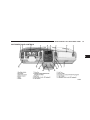
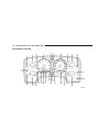
UNDERSTANDING YOUR INSTRUMENT PANEL
5
STARTING AND OPERATING
6
WHAT TO DO IN EMERGENCIES
7
MAINTAINING YOUR VEHICLE
8
MAINTENANCE SCHEDULES
9
IF YOU NEED CONSUMER ASSISTANCE
10
INDEX
. . . . . . . . . . . . . . . . . . . . . . . . . . . . . .9 2
. . . . . . . . . . . . . . . . . . . . . . . . . . . . . . 71 3
. . . . . . . . . . . . . . . . . . . . . . . . . . . . . . . . . . . 137 4
. . . . . . . . . . . . . . . . . . . . . . . . . . . . . . . . . . . . . . . . . . . . . . . . . 199 5
. . . . . . . . . . . . . . . . . . . . . . . . . . . . . . . . . . . . . . . . . . . . . . 293 6
. . . . . . . . . . . . . . . . . . . . . . . . . . . . . . . . . . . . . . . . . . . . . . . 319 7
. . . . . . . . . . . . . . . . . . . . . . . . . . . . . . . . . . . . . . . . . . . . . . . . . . 383 8
. . . . . . . . . . . . . . . . . . . . . . . . . . . . . . . . . . . . . . . . . 403 9
. . . . . . . . . . . . . . . . . . . . . . . . . . . . . . . . . . . . . . . . . . . . . . . . . . . . . . . . . . . . . . . . . . . . 413 10
INTRODUCTION
CONTENTS
m Introduction . . . . . . . . . . . . . . . . . . . . . . . . . . . 4
m Van Conversions/Campers . . . . . . . . . . . . . . . . . 5
m How To Use This Manual . . . . . . . . . . . . . . . . . . 5
m Vehicle Identification Number . . . . . . . . . . . . . . . 6
m Warnings And Cautions . . . . . . . . . . . . . . . . . . . 5
m Vehicle Modifications / Alterations . . . . . . . . . . . 7
1
4
INTRODUCTION
INTRODUCTION
This manual has been prepared with the assistance of
service and engineering specialists to acquaint you with
the operation and maintenance of your new vehicle. It is
supplemented by a Warranty Information Booklet and
various customer oriented documents. You are urged to
read these publications carefully. Following the instructions and recommendations in this manual will help
assure safe and enjoyable operation of your vehicle.
NOTE: After you read the manual, it should be stored
in the vehicle for convenient reference and remain with
the vehicle when sold, so that the new owner will be
aware of all safety warnings.
When it comes to service, remember that your dealer
knows your vehicle best, has the factory-trained technicians and genuine Mopart parts, and is interested in
your satisfaction.
WARNING!
Engine exhaust, some of its constituents, and certain
vehicle components contain or emit chemicals
known to the State of California to cause cancer and
birth defects or other reproductive harm. In addition,
certain fluids contained in vehicles and certain products of component wear contain or emit chemicals
known to the State of California to cause cancer and
birth defects or other reproductive harm.
INTRODUCTION
HOW TO USE THIS MANUAL
Consult the table of contents to determine which section
contains the information you desire.
The detailed index, at the rear of this manual, contains a
complete listing of all subjects.
WARNINGS AND CAUTIONS
This manual contains WARNINGS against operating
procedures which could result in an accident or bodily
injury. It also contains CAUTIONS against procedures
which could result in damage to your vehicle. If you do
not read this entire manual you may miss important
information. Observe all Warnings and Cautions.
5
VAN CONVERSIONS/CAMPERS
The Manufacturer’s Warranty does not apply to body
modifications or special equipment installed by van
conversion/camper manufacturers/ body builders. Such
equipment includes video monitors, VCRs, heaters,
stoves, refrigerators, etc. For warranty coverage and
service on these items, contact the applicable manufacturer.
Operating instructions for the special equipment installed by the conversion/camper manufacturer should
also be supplied with your vehicle. If these instructions
are missing, please contact your selling dealer for assistance in obtaining replacement documents from the
applicable manufacturer.
1
6
INTRODUCTION
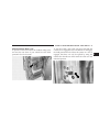
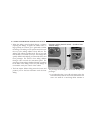
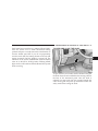
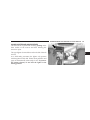
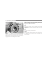
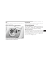
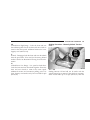
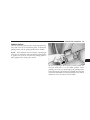
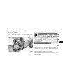
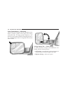
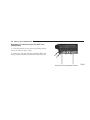
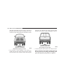
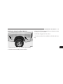
VEHICLE IDENTIFICATION NUMBER
The vehicle identification number (VIN) is found on a
stamped plate located on the left front corner of the
instrument panel pad, visible from outside of the vehicle
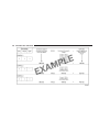
through the windshield. This number also appears on the
Automobile Information Disclosure Label affixed to a
window on your vehicle. Save this label for a convenient
record of your vehicle identification number and optional
equipment.
NOTE: It is illegal to remove the VIN plate.
INTRODUCTION
7
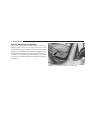
VEHICLE MODIFICATIONS / ALTERATIONS
1
WARNING!
Any modifications or alterations to this vehicle
could seriously affect its roadworthiness and safety
and may lead to an accident resulting in serious
injury or death.
THINGS TO KNOW BEFORE STARTING YOUR VEHICLE
2
CONTENTS
m A Word About Your Keys . . . . . . . . . . . . . . . . . .11
▫ Power Door Locks — If Equipped . . . . . . . . . .17
▫ Key-In-Ignition Reminder . . . . . . . . . . . . . . . .11
▫ Child Protection Door Lock . . . . . . . . . . . . . . .21
▫ Sentry Key — If Equipped . . . . . . . . . . . . . . . .11
m Remote Keyless Entry — If Equipped . . . . . . . . .22
m Ignition And Steering Lock . . . . . . . . . . . . . . . . .14
▫ To Unlock The Doors . . . . . . . . . . . . . . . . . . .23
▫ Manual Transmissions . . . . . . . . . . . . . . . . . . .14
▫ To Lock The Doors . . . . . . . . . . . . . . . . . . . . .24
▫ Automatic Transmissions . . . . . . . . . . . . . . . . .15
▫ Using The Panic Alarm . . . . . . . . . . . . . . . . . .25
m Door Key . . . . . . . . . . . . . . . . . . . . . . . . . . . . .16
▫ Programming Additional Transmitters . . . . . . . .26
m Door Locks . . . . . . . . . . . . . . . . . . . . . . . . . . . .16
▫ General Information . . . . . . . . . . . . . . . . . . . .27
▫ Manual Locks . . . . . . . . . . . . . . . . . . . . . . . . .16
▫ Transmitter Battery Service . . . . . . . . . . . . . . .28
10
THINGS TO KNOW BEFORE STARTING YOUR VEHICLE
m Security Alarm System — If Equipped . . . . . . . . .29
▫ Rearming Of The System . . . . . . . . . . . . . . . . .29
▫ To Set The Alarm . . . . . . . . . . . . . . . . . . . . . .29
▫ To Disarm The System . . . . . . . . . . . . . . . . . . .30
▫ Enhanced Driver Seat Belt Reminder System
(BeltAlert) . . . . . . . . . . . . . . . . . . . . . . . . . . .43
▫ Seat Belts And Pregnant Women . . . . . . . . . . . .44
▫ Seat Belt Extender . . . . . . . . . . . . . . . . . . . . . .44
m Windows . . . . . . . . . . . . . . . . . . . . . . . . . . . . .31
▫ Driver And Right Front Passenger Supplemental
Restraint System (SRS)—Airbag . . . . . . . . . . . .45
▫ Power Windows—If Equipped . . . . . . . . . . . . .31
▫ Child Restraint . . . . . . . . . . . . . . . . . . . . . . . .55
▫ Sliding Rear Window—If Equipped . . . . . . . . .32
m Engine Break-In Recommendations . . . . . . . . . . .67
▫ Wind Buffeting . . . . . . . . . . . . . . . . . . . . . . . .33
m Safety Tips . . . . . . . . . . . . . . . . . . . . . . . . . . . .68
m Occupant Restraints . . . . . . . . . . . . . . . . . . . . . .33
▫ Transporting Passengers . . . . . . . . . . . . . . . . .68
▫ Lap/Shoulder Belts . . . . . . . . . . . . . . . . . . . . .34
▫ Lock Your Vehicle . . . . . . . . . . . . . . . . . . . . . .69
▫ Adjustable Upper Shoulder Belt Anchorage . . . .41
▫ Exhaust Gas . . . . . . . . . . . . . . . . . . . . . . . . . .69
▫ Automatic Locking Mode (If Equipped) . . . . . .41
▫ Center Lap Belts . . . . . . . . . . . . . . . . . . . . . . .42
▫ Seat Belt Pretensioners . . . . . . . . . . . . . . . . . . .42
▫ Safety Checks You Should Make Inside The
Vehicle . . . . . . . . . . . . . . . . . . . . . . . . . . . . . .70
▫ Safety Checks You Should Make Outside The
Vehicle . . . . . . . . . . . . . . . . . . . . . . . . . . . . . .70
THINGS TO KNOW BEFORE STARTING YOUR VEHICLE
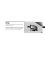
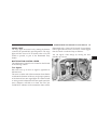
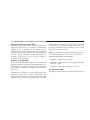
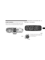
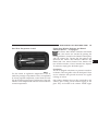
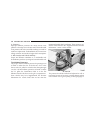
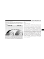
A WORD ABOUT YOUR KEYS
The double sided keys may be inserted into the locks
with either side up. The keys for your new vehicle are
enclosed in a plastic bag with a bar code label affixed to
the front. The bar code can be used to order duplicate
keys from your dealer or a locksmith. If you received
your keys without the bag, ask your dealer to give you
the number.
Key-In-Ignition Reminder
If you open the driver’s door when the key is in the
ignition switch, a chime will sound to remind you to
remove the key.
CAUTION!
An unlocked vehicle is an invitation to thieves.
Always remove the key from the ignition and lock
all the doors when leaving the vehicle unattended.
11
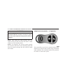
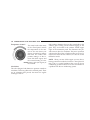
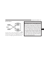
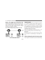
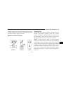
SENTRY KEY — IF EQUIPPED
With this system, an electronically coded ignition key
sends a signal to the vehicle electronics. If the electronics
recognizes the signal, the vehicle will start and continue
to run. If the system does not recognize the signal the
vehicle will start and run for a maximum of 2 seconds
after the initial key ON. After six unsuccessful attempts
at starting, the system will shut down until the correct
key is used.
NOTE: The Sentry Key Immobilizer System is not
compatible with remote starting systems. Use of these
systems may result in vehicle starting problems and a
loss of security protection. Additional Sentry Keys or
Mobil Speed-pass™ devices held against or immediately
adjacent to the ignition key when starting the engine may
cause vehicle starting problems. If a problem occurs,
remove the Sentry Key from the key-ring and attempt to
start the vehicle again. Pagers, cell phones, walkman, etc.
will have no effect on this system.
2
12
THINGS TO KNOW BEFORE STARTING YOUR VEHICLE
The 9Security Light9, located in the instrument cluster,
will illuminate for about 2 seconds when the ignition
switch is first turned to the ON position. If the vehicle
electronics do not receive a valid signal from the ignition
key, the 9Security Light9 will flash continuously to signal
that the vehicle has been immobilized. If the 9Security
Light9 remains on during vehicle operation, it indicates a
fault in the system electronics. If this option was ordered,
all of the keys provided with your new vehicle have been
programmed to the vehicle electronics.
Replacement Keys
NOTE: Only keys that have been programmed to the
vehicle electronics can be used to start the vehicle. Once
a Sentry Key has been programmed to a vehicle, it cannot
be programmed to any other vehicle.
At the time of purchase, the original owner is provided
with a four digit PIN number. This number is required
for dealer replacement of keys. Duplication of keys may
be performed at an authorized dealer or by using the
Customer Key Programming procedure. This procedure
consists of programming a blank key to the vehicle
electronics. A blank key is one which has never been
programmed and needs to be cut.
NOTE: When having the Sentry Key System serviced,
bring all vehicle keys to the dealer.
THINGS TO KNOW BEFORE STARTING YOUR VEHICLE
Customer Key Programming
You can program new keys to the system if you have two
valid keys by doing the following:
1. Insert the first valid key into the ignition and turn the
ignition to the ON position for at least 3 seconds but no
longer than 15 seconds. Turn the ignition back to the OFF
position and remove the first key.
2. Insert the second valid key and switch the ignition to
the ON position within 15 seconds. After 10 seconds the
9Security Light9 will begin to flash. Turn the ignition back
to the OFF position and remove the second key.
3. Insert a blank Sentry Key into the ignition and switch
the ignition to the ON position within 60 seconds of
having removed the second key. After 10 seconds the
9Security Light9 will stop flashing, then turn on for 3
seconds; then turn off.
13
The new Sentry Key has been programmed. Repeat this
process to program up to an additional 6 keys. A maximum of 8 keys can be programmed to the system,
including the original keys provided with the vehicle.
General Information
This device complies with part 15 of FCC rules and with
RS-210 of Industry Canada. Operation is subject to the
following conditions:
1. This device may not cause harmful interference.
2. This device must accept any interference that may be
received including interference that may cause undesired
operation.
NOTE: Changes or modifications not expressly approved by the party responsible for compliance could
void the user’s authority to operate the equipment.
2
14
THINGS TO KNOW BEFORE STARTING YOUR VEHICLE
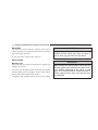
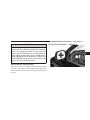
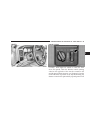
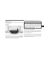
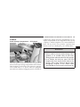
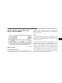
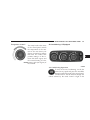
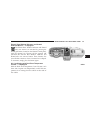
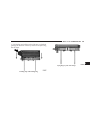
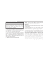
IGNITION AND STEERING LOCK
Manual Transmissions
When the steering wheel is in the LOCK position, the
steering and ignition systems are locked to provide
antitheft protection for your vehicle. It may be difficult to
turn the key from the LOCK position when starting your
vehicle. Move the steering wheel left and right while
turning the key until it turns easily. To remove the key,
depress and hold the release button located between the
ignition switch and the instrument panel. Turn the ignition key to LOCK and remove the key.
Manual Transmissions
THINGS TO KNOW BEFORE STARTING YOUR VEHICLE
15
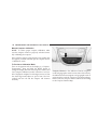
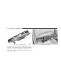
Automatic Transmissions
In the LOCK position, the steering and ignition systems
are locked to provide antitheft protection for your vehicle. It may be difficult to turn the key from the LOCK
position when starting your vehicle. Move the steering
wheel left and right while turning the key until it turns
easily. The key can be inserted or withdrawn only in the
LOCK position. Push in on the key in the ignition lock
cylinder to rotate to the LOCK position.
NOTE: The steering wheel will the lock when the key is
removed, and the steering wheel is turned around 115
degrees from center clockwise and around 65 degrees
counter-clockwise.
2
Automatic Transmissions
NOTE: On vehicles equipped with an automatic transmission, the key cannot be turned to LOCK until the
selector is in the PARK position. Do not attempt to pull
the shift lever out of PARK after the key is in the LOCK
position.
16
THINGS TO KNOW BEFORE STARTING YOUR VEHICLE
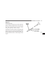
DOOR KEY
The same key used to start the vehicle is also used to
unlock the doors. To unlock the vehicle doors, insert the
key into the lock and turn.
To lock the doors, insert the key and turn.
WARNING!
For personal security and safety in the event of an
accident, lock the vehicle doors when you drive as
well as when you park and leave the vehicle.
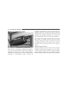
DOOR LOCKS
Manual Locks
Front and Rear doors may be locked, by moving the lock
plunger up or down.
All doors may be opened with the inside door handle
without lifting the lock plunger. Doors locked before
closing will remain locked when closed.
The ignition key will unlock all the locks on your vehicle.
WARNING!
When leaving the vehicle always remove the key
from the ignition lock, and lock your vehicle. Do not
leave children unattended in the vehicle, or with
access to an unlocked vehicle. Unsupervised use of
vehicle equipment may cause severe personal injuries and death.
THINGS TO KNOW BEFORE STARTING YOUR VEHICLE
17
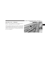
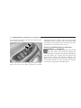
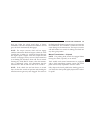
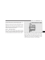
Power Door Locks — If Equipped
NOTE: Vehicles equipped with remote keyless entry do
not have a passenger side door lock cylinder.
Vehicles equipped with power door locks can be locked
or unlocked from inside by either the use of the door lock
switches located on the front doors or by pressing the
LOCK or UNLOCK buttons on the Remote Keyless Entry
key fob (if equipped).
2
18
THINGS TO KNOW BEFORE STARTING YOUR VEHICLE
Central Locking — If Equipped
Vehicles with security will have a feature called 9Central
Locking9. When the key is placed in the door cylinder
and turned to the 9Unlock9 position, the security will be
disarmed, the illuminated entry will be turned on and
that door will be mechanically unlocked. If the key is
once again turned to the unlock position within 5 seconds
of the first unlock, the remaining doors will unlock. If the
key is turned to the 9Lock9 position while all doors are
closed, illuminated entry will be canceled, security will
begin arming, and all doors will lock.
As a safety feature the doors will not lock when using the
door lock switches during the following condition:
1. The driver’s door is open while the key is in the
ignition.
Automatic Door Locks
If this feature is enabled, your door locks will lock
automatically when the vehicle’s speed exceeds 15 mph.
This feature is enabled when your vehicle is shipped
from the assembly plant and can be disabled by using the
following procedure:
1. Enter your vehicle and close all doors.
THINGS TO KNOW BEFORE STARTING YOUR VEHICLE
2. Fasten your seat belt (Fastening the seat belt will
cancel any chiming that may confuse you during this
programming procedure).
3. Place the key into the ignition.
4. Within 10 seconds cycle the key from the OFF position
to the ON position four times; ending in the ON position
( Do not start the engine ).
5. Within 30 seconds, press the driver’s door lock switch
in the LOCK direction.
6. A single chime will be heard to indicate the feature has
been disabled.
7. To reactivate this feature, repeat the above steps.
8. If a chime is not heard, program mode was canceled
before the feature could be disabled. If necessary, repeat
the above procedure.
19
Auto Unlock Feature
This feature unlocks all the doors of the vehicle when the
driver’s door is opened first. The following conditions
must be met:
• The driver’s door must be opened first.
• The Automatic Door Lock feature must be enabled.
• The doors of the vehicle must be locked automatically
by the Automatic Door Lock feature.
• The vehicle is in P (Park) and the ignition switch is in
the Off position.
This feature will not operate if any of the conditions
above are not met or following has occurred:
• Any manual operation of a door lock switch has
occurred.
2
20
THINGS TO KNOW BEFORE STARTING YOUR VEHICLE
Auto Unlock Feature Programming
This feature is enabled when your vehicle is shipped
from the assembly plant and can be disabled by using the
following procedure:
Customer Programming sequence to disable or enable:
1. Enter your vehicle and close all doors.
2. Fasten your seat belt (fastening the seat belt will cancel
any chiming that may be confusing during this programming procedure).
3. Insert the key into the ignition.
4. Within 4 seconds, cycle the key from the OFF position
to the ON position four times ending in the ON position
(do not start the engine).
5. Within 30 seconds, press the driver’s door lock switch
in the UNLOCK direction.
6. A single chime will sound to indicate the feature has
been changed.
7. To reactivate the feature, repeat the above steps.
8. If a chime is not heard, program mode was canceled
before the feature could be changed. If necessary repeat
the above procedure.
THINGS TO KNOW BEFORE STARTING YOUR VEHICLE
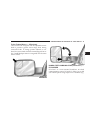
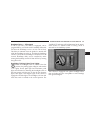
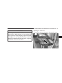
Child Protection Door Lock
To provide a safer environment for children riding in the
rear seat, the rear doors of your vehicle have the childprotection door lock system.
21
To use the system, open each rear door and slide the
control UP to engage the locks and DOWN to disengage
the child-protection locks. When the system on a door is
engaged, that door can only be opened by using the
outside door handle even if the inside door lock is in the
unlocked position.
2
22
THINGS TO KNOW BEFORE STARTING YOUR VEHICLE
WARNING!
REMOTE KEYLESS ENTRY — IF EQUIPPED
Avoid trapping anyone in a vehicle in a collision.
Remember that the rear doors can only be opened
from the outside when the child protection locks are
engaged.
NOTE: After setting the child protection door lock
system, always test the door from the inside to make
certain it is in the desired position.
NOTE: For emergency exit with the system engaged,
move the door lock switch to the UNLOCK position, roll
down the window and open the door with the outside
door handle.
This system allows you to lock or unlock the doors from
distances up to about 23 feet (7 meters) using a hand held
radio transmitter. The transmitter need not be pointed at
the vehicle to activate the system.
THINGS TO KNOW BEFORE STARTING YOUR VEHICLE
To unlock the doors:
Press and release the UNLOCK button on the key fob
once to unlock only the driver’s door or twice to unlock
all the doors. When the UNLOCK button is pressed, the
illuminated entry will initiate, the parking lights will
flash on twice and if installed, the cargo lamp will turn on
for 30 seconds.
The system can be programmed to unlock all the doors
upon the first UNLOCK button press by using the
following procedure:
1. Enter your vehicle and close all doors.
2. Fasten your seat belt.(Fastening the seat belt will
cancel any chiming that may confuse you during this
programming procedure).
3. Place the key into the ignition.
23
4. Turn the ignition to the ON position ( Do not start the
engine ).
5. Press and hold the UNLOCK button on a programmed
(i.e. functional) key fob.
6. Continue to hold the UNLOCK button, wait at least 4
seconds, but no longer than 10 seconds, then press and
hold the LOCK button.
7. When a single chime is heard, release both buttons.
8. Turn the ignition to the OFF position or wait 60
seconds.
9. To reactivate this feature, repeat the above steps.
10. If a chime is not heard, program mode was canceled
before the feature could be changed. If necessary, repeat
the above procedure.
2
24
THINGS TO KNOW BEFORE STARTING YOUR VEHICLE
To lock the doors:
Press and release the LOCK button on the transmitter to
lock all doors. If the ignition is OFF, when the doors are
locked, the parking lights will flash on once and the horn
will chirp once.
The horn chirp feature will be shipped from the assembly
plants activated. If desired this feature can be disabled by
using the following procedure:
1. Enter your vehicle and close all doors.
2. Fasten your seat belt (fastening the seat belt will cancel
any chiming that may confuse you during this programming procedure).
3. Place the key into the ignition.
4. Turn the ignition to the ON position ( Do not start the
engine ).
5. Press and hold the LOCK button on a programmed
(i.e. functional) key fob.
6. Continue to hold the LOCK button, wait at least 4
seconds, but no longer than 10 seconds, then press and
hold the UNLOCK button.
7. When a single chime is heard, release both buttons.
8. Turn the ignition to the OFF position or wait 60
seconds.
9. Test the horn chirp feature by pressing the LOCK
button on the key fob with the ignition in the OFF
position, or the key removed.
10. To reactivate this feature, repeat the above steps.
THINGS TO KNOW BEFORE STARTING YOUR VEHICLE
Vehicles will be shipped from the assembly plants with
the park lamp flash feature activated. If desired, this
feature can be disabled by using the following procedure:
1. Enter your vehicle and close all doors.
2. Fasten your seat belt (fastening the seat belt will cancel
any chiming that may confuse you during this programming procedure).
3. Place the key into the ignition.
4. Turn the ignition to the ON position ( Do not start the
engine ).
5. Press and hold the LOCK button on a programmed
(i.e. functional) key fob.
6. Continue to hold the LOCK button, wait at least 4
seconds, but no longer than 10 seconds, then press and
hold the PANIC button.
7. When a single chime is heard, release both buttons.
25
8. Turn the ignition to the OFF position or wait 60
seconds.
9. Test the park lamp flash feature by pressing the LOCK
button on the key fob with the ignition in the OFF
position or the key removed.
10. To reactivate this feature, repeat the above steps.
11. If a chime is not heard, program mode was canceled
before the feature could be disabled. If necessary, repeat
the above procedure.
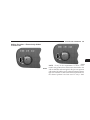
Using the Panic Alarm
To activate the Panic mode while the ignition is OFF press
and release the PANIC button on the transmitter once.
When the Panic mode is activated, the interior lights will
illuminate, the headlamps and parking lights will flash,
and the horn will sound.
To cancel the Panic mode press and release the PANIC
button on the transmitter a second time. Panic mode will
2
26
THINGS TO KNOW BEFORE STARTING YOUR VEHICLE
automatically cancel after 3 minutes or if the vehicle is
started and exceeds 15 mph. During the Panic Mode, the
door locks and remote keyless entry systems will function normally. Panic mode will not disarm the security
system on vehicles so equipped.
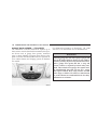
Programming Additional Transmitters
Vehicles with the keyless entry option will be shipped
from the assembly plants with two key fob transmitters
programmed only for that vehicle. A total of four fobs can
be programmed for your vehicle. Additional fobs can be
programmed to your vehicle through the use of a currently programmed fob.
NOTE: When entering program mode using that fob,
ALL currently programmed fobs will be erased and you
will have to reprogram them for your vehicle. However,
if program mode is entered and no action is performed,
the previously programmed fobs will continue to function.
1. Enter your vehicle and close all doors.
2. Fasten your seat belt (fastening the seat belt will cancel
any chiming that may confuse you during this programming procedure).
3. Place the key into the ignition.
4. Turn the ignition to the ON position ( Do not start the
engine ).
5. Press and hold the UNLOCK button on a programmed
(i.e. functional) key fob.
6. Continue to hold the UNLOCK button, wait at least 4
seconds, but no longer than 10 seconds, then press and
hold the PANIC button.
7. When a single chime is heard, release both buttons.
The chime indicates that the system is in program mode.
8. Press and release both the LOCK and UNLOCK
buttons, simultaneously on the fob to be programmed.
THINGS TO KNOW BEFORE STARTING YOUR VEHICLE
9. A single chime will be heard. The chime indicates that
the fob has been recognized.
10. Within 4 seconds of hearing the chime, press and
release any button on the fob being programmed.
11. A single chime will be heard. The chime indicates
that the fob has been programmed.
12. Repeat steps 8 to 11 for a total of 4 fobs.
13. Turn the ignition to the OFF position or wait 60
seconds to exit program mode.
14. Your vehicle will remain in program mode for up to
60 seconds from when the original chime (i.e. Step #7)
was heard. After 60 seconds, all programmed fobs will
function normally.
NOTE: If you do not have a programmed transmitter,
contact your dealer for details.
27
General Information
This device complies with part 15 of FCC rules and with
RS-210 of Industry Canada. Operation is subject to the
following conditions:
1. This device may not cause harmful interference.
2. This device must accept any interference that may be
received including interference that may cause undesired
operation.
NOTE: Changes or modifications not expressly approved by the party responsible for compliance could
void the user’s authority to operate the equipment.
If your Keyless Entry Transmitter fails to operate from a
normal distance, check for these two conditions.
1. Weak batteries in transmitter. The expected life of the
batteries is from one to two years.
2
28
THINGS TO KNOW BEFORE STARTING YOUR VEHICLE
2. Closeness to a radio transmitter such as a radio station
tower, airport transmitter, and some mobile or CB radios.
NOTE: Do not touch the battery terminals that are on
the back housing or the printed circuit board.
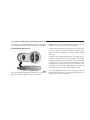
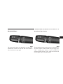
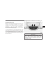
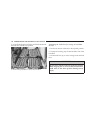
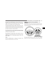
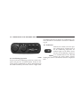
Transmitter Battery Service
1. With transmitter buttons facing down, use a flat blade
or dime to pry the two halves of the transmitter apart.
Make sure not to damage the rubber gasket during
removal.
2. Remove and replace the batteries. Be careful not to
disturb the metal terminal near the batteries. Install the
batteries with the positive terminal up, reference the note
9+ SIDE UP9 on the inside of the bottom half of the
transmitter case. Avoid touching the new batteries with
your fingers. Skin oils may cause battery deterioration. If
you touch a battery, clean it with rubbing alcohol.
The recommended replacement battery is a 3V lithium
2016 cell. This transmitter requires two batteries.
3. To reassemble the transmitter case snap the two halves
together. Make sure there is an even gap between the two
halves. Test transmitter operation.
THINGS TO KNOW BEFORE STARTING YOUR VEHICLE
SECURITY ALARM SYSTEM — IF EQUIPPED
This system monitors the vehicle doors and ignition for
unauthorized operation. When the alarm is activated, the
system provides both audible and visual signals. For the
first 3 minutes the horn will sound and the headlights
and security telltale will flash repeatedly. For an additional 15 minutes only the headlights and security telltale
will flash. The engine will run only if a valid Sentry Key
is used to start the vehicle. Use of the Sentry Key will
disable the alarm.
Rearming of the System:
The security system will rearm itself after the 15 additional minutes of headlights and security telltale flashing,
if the system has not been disabled. If the condition
which initiated the alarm is still present, the system will
ignore that condition and monitor the remaining doors
and ignition.
29
To Set the Alarm:
The alarm will set when you use the power door locks,
turn the key in the driver’s door lock cylinder, or use the
Keyless Entry transmitter to lock the doors. After all the
doors are locked and closed the SECURITY light in the
instrument cluster will flash rapidly to signal that the
system is arming. The security light in the instrument
panel cluster will flash rapidly for about 16 seconds to
indicate that the alarm is being set. After the alarm is set,
the security light will flash at a slower rate to indicate
that the system is armed.
NOTE: If the SECURITY light stays on continuously
during vehicle operation, have the system checked by
your dealer.
2
30
THINGS TO KNOW BEFORE STARTING YOUR VEHICLE
To Disarm the System:
Use the Keyless Entry transmitter or the key to turn the
driver’s door lock to the unlock position. If something
has triggered the system in your absence, the horn will
sound three times when you unlock the doors and the
security lamp will flash for 30 seconds. Check the vehicle
for tampering.
The Security system will also disarm, if the vehicle is
started with a programmed Sentry Key. If an unprogrammed Sentry Key is used to start a vehicle, the engine
will run for 2 seconds and then the security alarm will be
initiated. To exit alarming mode, press the transmitter
Unlock button, unlock the driver’s door using the key
cylinder, or start the vehicle with a programmed Sentry
Key.
The Security Alarm System is designed to protect your
vehicle; however, you can create conditions where the
system will arm unexpectedly. If you remain in the
vehicle and lock the doors with the transmitter, the alarm
will sound when you pull the door handle to exit. You
may also accidentally disarm the system by unlocking
the driver’s door with the door key and then locking it
manually with the lock plunger. The door will be locked
but the Security Alarm will not arm.
THINGS TO KNOW BEFORE STARTING YOUR VEHICLE
31
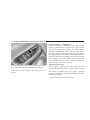
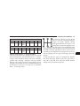
WINDOWS
Power Windows—If Equipped
2
The control on the left front door panel has up-down
switches that give you fingertip control of all power
windows. There is a single opening and closing switch on
the front passenger door for passenger window control
and on the rear doors of Quad Cab models. The windows
will operate only when the ignition switch is turned to
the ON or ACC (Accessory) position.
32
THINGS TO KNOW BEFORE STARTING YOUR VEHICLE
Auto Down (Driver’s Side Only)
The driver’s window switch has an Auto Down feature.
Press the window switch past the detent, release, and the
window will go down automatically.
Window Lockout Switch (4 Door Models Only)
The window lockout switch on the driver’s door allows
you to disable the window control on the other doors. To
disable the window controls on the other doors, press the
window lock button. To enable the window controls,
press the window control button again.
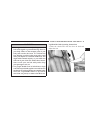
Sliding Rear Window—If Equipped
A locking device in the center of the window helps to
prevent entry from the rear of the vehicle. Squeeze the
lock to release the window.
THINGS TO KNOW BEFORE STARTING YOUR VEHICLE
WIND BUFFETING
Wind buffeting can be described as the perception of
pressure on the ears or a helicopter type sound in the
ears. Your vehicle may exhibit wind buffeting with the
windows down or partially open positions. This is a
normal occurrence and can be minimized. If the buffeting
occurs with the rear windows open, open the front and
rear windows together to minimize the buffeting.
OCCUPANT RESTRAINTS
Some of the most important safety features in your
vehicle are the restraint systems. These include the front
and rear seat belts for the driver and all passengers, front
airbags for both the driver and front passenger and, if so
equipped, window bags for the driver and passengers
seated next to a window. If you will be carrying children
too small for adult-size belts, your seat belts also can be
used to hold infant and child restraint systems.
33
Please pay close attention to the information in this
section. It tells you how to use your restraint system
properly to keep you and your passengers as safe as
possible.
WARNING!
In a collision, you and your passengers can suffer
much greater injuries if you are not properly buckled up. You can strike the interior of your vehicle or
other passengers, or you can be thrown out of the
vehicle. Always be sure you and others in your
vehicle are buckled up properly.
Buckle up even though you are an excellent driver, even
on short trips. Someone on the road may be a poor driver
and cause a collision that includes you. This can happen
far away from home or on your own street.
2
34
THINGS TO KNOW BEFORE STARTING YOUR VEHICLE
Research has shown that seat belts save lives, and that
they can reduce the seriousness of injuries in a collision.
Some of the worst injuries happen when people are
thrown from the vehicle. Seat belts reduce the possibility
of ejection and the risk of injury caused by striking the
inside of the vehicle. Everyone in a motor vehicle should
be belted at all times.
Lap/Shoulder Belts
All seating positions except the Quad Cab front center
seating position have combination lap/shoulder belts.
The belt webbing retractor is designed to lock during
very sudden stops or collisions. This feature allows the
shoulder part of the belt to move freely with you under
normal conditions. But in a collision, the belt will lock
and reduce the risk of your striking the inside of the
vehicle or being thrown out.
WARNING!
It is extremely dangerous to ride in a cargo area,
inside or outside of a vehicle. In a collision, people
riding in these areas are more likely to be seriously
injured or killed.
Do not allow people to ride in any area of your
vehicle that is not equipped with seats and seat belts.
Be sure everyone in your vehicle is in a seat and
using a seat belt properly.
THINGS TO KNOW BEFORE STARTING YOUR VEHICLE
WARNING!
• Wearing a seat belt incorrectly is dangerous. Seat
belts are designed to go around the large bones of
your body. These are the strongest parts of your
body and can take the forces of a collision the
best. Wearing your belt in the wrong place could
make your injuries in a collision much worse. You
might suffer internal injuries, or you could even
slide out of part of the belt. Follow these instructions to wear your seat belt safely and to keep
your passengers safe, too.
• Two people should never be belted into a single
seat belt. People belted together can crash into one
another in an accident, hurting one another badly.
Never use a lap/shoulder belt or a lap belt for
more than one person, no matter what their size.
35
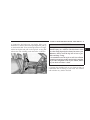
Lap/Shoulder Belt Operating Instructions
1. Enter the vehicle and close the door. Sit back and
adjust the seat.
2
36
THINGS TO KNOW BEFORE STARTING YOUR VEHICLE
2. The seat belt latch plate is above the back of the front
seat, next to your arm in the rear seat. Grasp the latch
plate and pull out the belt. Slide the latch plate up the
webbing as far as necessary to allow the belt to go around
your lap.
3. When the belt is long enough to fit, insert the latch
plate into the buckle until you hear a “click.”
WARNING!
• A belt buckled into the wrong buckle will not
protect you properly. The lap portion could ride too
high on your body, possibly causing internal injuries.
Always buckle your belt into the buckle nearest you.
• A belt that is too loose will not protect you as well. In
a sudden stop you could move too far forward, increasing the possibility of injury. Wear your seat belt snugly.
• A belt that is worn under your arm is very dangerous. Your body could strike the inside surfaces of the
vehicle in a collision, increasing head and neck injury.
And a belt worn under the arm can cause internal
injuries. Ribs aren’t as strong as shoulder bones. Wear
the belt over your shoulder so that your strongest
bones will take the force in a collision.
• A shoulder belt placed behind will not protect you
from injury during a collision. You are more likely to
hit your head in a collision if you do not wear your
shoulder belt. The lap and shoulder belt are meant to
be used together.
THINGS TO KNOW BEFORE STARTING YOUR VEHICLE
4. Position the lap belt across your thighs, below your
abdomen. To remove slack in the lap belt portion, pull up
on the shoulder belt. To loosen the lap belt if it is too tight,
tilt the latch plate and pull on the lap belt. A snug belt
reduces the risk of sliding under the belt in a collision.
37
WARNING!
• A lap belt worn too high can increase the risk of
internal injury in a collision. The belt forces won’t
be at the strong hip and pelvic bones, but across your
abdomen. Always wear the lap belt as low as possible and keep it snug.
• A twisted belt can’t do its job as well. In a collision
it could even cut into you. Be sure the belt is straight.
If you can’t straighten a belt in your vehicle, take it
to your dealer and have it fixed.
5. Position the shoulder belt on your chest so that it is
comfortable and not resting on your neck. The retractor
will withdraw any slack in the belt.
2
38
THINGS TO KNOW BEFORE STARTING YOUR VEHICLE
6. To release the belt, push the red button on the buckle.
The belt will automatically retract to its stowed position.
If necessary, slide the latch plate down the webbing to
allow the belt to retract fully.
WARNING!
A frayed or torn belt could rip apart in a collision
and leave you with no protection. Inspect the belt
system periodically, checking for cuts, frays, or loose
parts. Damaged parts must be replaced immediately.
Do not disassemble or modify the system. Seat belt
assemblies must be replaced after a collision if they
have been damaged (bent retractor, torn webbing,
etc.) or if the airbag deployed.
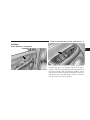
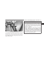
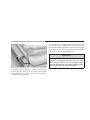
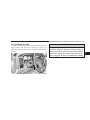
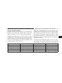
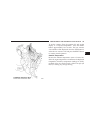
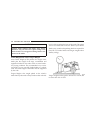
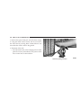
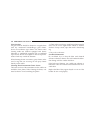
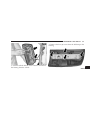
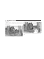
Standard Cab Front Center Three Point Belt
1. The front center seat belt on the Standard Cab may be
disconnected to open up utilization of the storage areas
behind the front seats. The black latch plate can be
detached from the black keyed seat belt buckle located on
the inboard side of the passenger seat. Insert the vehicle
ignition key into the center white slot on the black buckle.
The black buckle latch plate can be removed when the
key is pressed into the buckle. Allow the retractor to take
up the surplus webbing, and the buckles will hang
vertically from the cab back exit bezel, thus freeing up all
the area behind the front seats.
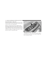
THINGS TO KNOW BEFORE STARTING YOUR VEHICLE
39
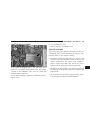
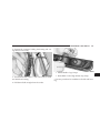
WARNING!
Detaching Buckle with Key
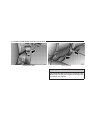
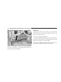
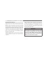
2. To reattach the seat belt to the front center seat, pull
the black buckle latch plate forward from the cab back
panel and insert it into the black keyed buckle until there
is an audible click. Refer to the previous section for the
proper seat belt usage.
• If the black latch and black buckle are not properly connected when the seat belt is used by an
occupant, the seat belt will not be able to provide
proper restraint and will increase the risk of
injury in a collision.
• When reattaching the black latch and black
buckle, ensure the seat belt webbing is not
twisted. If the webbing is twisted, follow the
preceding procedure to detach the black latch and
black buckle, untwist the webbing, and reattach
the black latch and black buckle.
2
40
THINGS TO KNOW BEFORE STARTING YOUR VEHICLE
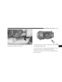
Inserting Latch Plate
In Use Position
WARNING!
If the black latch and buckle are not connected when
the seat belt is used by an occupant, the seat belt will
not restrain you properly.
THINGS TO KNOW BEFORE STARTING YOUR VEHICLE
Adjustable Upper Shoulder Belt Anchorage
In the front row outboard seats, the shoulder belt can be
adjusted upward or downward to help position the belt
away from your neck. Press the button located on the
upper belt guide, and then move it up or down to the
position that serves you best.
41
As a guide, if you are shorter than average, you will
prefer a lower position, and if you are taller than average,
you’ll prefer a higher position. When you release the
anchorage, try to move it up or down to make sure that
it is locked in position.
Automatic Locking Mode (if Equipped)
In this mode, the shoulder belt is automatically prelocked. The belt will still retract to remove any slack in
the shoulder belt. The automatic locking mode is only
available on the front passenger side belt.
When To Use The Automatic Locking Mode
Anytime a child safety seat is installed in a passenger
front seating position. Children 12 years old and under
should be properly restrained in the rear seat whenever
possible.
How To Use The Automatic Locking Mode
1. Buckle the combination lap and shoulder belt.
2
42
THINGS TO KNOW BEFORE STARTING YOUR VEHICLE
2. Grasp the shoulder portion and pull downward until
the entire belt is extracted.
3. Allow the belt to retract. As the belt retracts, you will
hear a clicking sound. This indicates the safety belt is
now in the automatic locking mode.
How To Disengage The Automatic Locking Mode
Disconnect the combination lap/shoulder belt and allow
it to retract completely to disengage the automatic locking mode and activate the vehicle sensitive (emergency)
locking mode.
Center Lap Belts
The center seating position for the Quad Cab front seat
has a lap belt only. To fasten the lap belt, slide the latch
plate into the buckle until you hear a 9click.9 To lengthen
the lap belt, tilt the latch plate and pull. To remove slack,
pull the loose end of the webbing. Wear the lap belt snug
against the hips. Sit back and erect in the seat, then adjust
the belt as tightly as is comfortable.
WARNING!
• A lap belt worn too loose or too high is dangerous.
• A belt worn too loose can allow you to slip down
and under the belt in a collision.
• A belt that is too loose or too high will apply crash
forces to the abdomen, not to the stronger hip
bones. In either case, the risk of internal injuries
is greater. Wear a lap belt low and snug.
Seat Belt Pretensioners
The seat belts for both front seating positions are
equipped with pretensioning devices that are designed to
remove any slack from the seat belt system in the event of
a collision. These devices improve the performance of the
seat belt by assuring that the belt is tight about the
occupant early in a collision. Pretensioners work for all
size occupants, including those in child restraints.
THINGS TO KNOW BEFORE STARTING YOUR VEHICLE
NOTE: These devices are not a substitute for proper seat
belt placement by the occupant. The seat belt still must be
worn snugly and positioned properly.
The pretensioners are triggered by the airbag control
module. Like the airbags, the pretensioners are single use
items. After a collision that is severe enough to deploy
the airbags and pretensioners, both must be replaced.
Enhanced Driver Seat Belt Reminder System
(BeltAlert)
If the driver’s seat belt has not been buckled within 60
seconds of starting the vehicle and if the vehicle speed is
greater than 5 mph (8 km/h), the Enhanced Warning
System (BeltAlert) will alert the driver to buckle their seat
belt. The driver should also instruct all other occupants to
buckle their seat belts. Once the warning is triggered, the
Enhanced Warning System (BeltAlert) will continue to
chime and flash the Seat Belt Warning Light for 96
seconds or until the driver’s seat belt is buckled. The
43
Enhanced Warning System (BeltAlert) will be reactivated
if the driver’s seat belt is unbuckled for more than 10
seconds and the vehicle speed is greater than 5 mph (8
km/h).
The Enhanced Warning System (BeltAlert) can be enabled or disabled by your authorized dealer or by
following these steps:
NOTE: The following steps must occur within the first
60 seconds of the ignition switch being turned to the ON
or START position. DaimlerChrysler does not recommend deactivating the Enhanced Warning System
(BeltAlert).
1. Turn the ignition switch to the OFF position and
buckle the driver’s seat belt.
2. Start the engine and wait for the Seat Belt Warning
Light to turn off.
2
44
THINGS TO KNOW BEFORE STARTING YOUR VEHICLE
3. Within 60 seconds of starting the vehicle, unbuckle
and then re-buckle the driver’s seat belt at least three
times within 10 seconds, ending with the seat belt
buckled.
Seat Belts and Pregnant Women
We recommend that pregnant women use seat belts
throughout their pregnancies. Keeping the mother safe is
the best way to keep the baby safe.
4. Turn off the engine. A single chime will sound to
signify that you have successfully completed the programming.
Pregnant women should wear the lap part of the belt
across the thighs and as snug against the hips as possible.
Keep the belt low so that it does not come across the
abdomen. That way the strong bones of the hips will take
the force if there is a collision.
The Enhanced Warning System (BeltAlert) can be reactivated by repeating this procedure.
NOTE: Although the Enhanced Warning System (BeltAlert) has been deactivated, the Seat Belt Warning Light
will continue to illuminate while the driver’s seat belt
remains unbuckled.
Seat Belt Extender
If a seat belt is too short, even when fully extended, your
dealer can provide you with a seat belt extender. This
extender should be used only if the existing belt is not
long enough. When it is not required, remove the extender and store it.
THINGS TO KNOW BEFORE STARTING YOUR VEHICLE
WARNING!
45
These airbags are certified to the new Federal regulations
that allow less forceful deployments.
Using a seat belt extender when not needed can
increase the risk of injury in a collision. Only use the
seat belt extender when the lap belt is not long
enough when it is worn low and snug, and in the
recommended seating positions. Remove and store
the extender when not needed.
Driver And Right Front Passenger Supplemental
Restraint System (SRS)—Airbag
This vehicle has front airbags for both the driver and
front passenger as a supplement to the seat belt restraint
systems. The driver’s front airbag is mounted in the
center of the steering wheel. The passenger’s front airbag
is mounted in the instrument panel, above the glove
compartment. The words SRS AIRBAG are embossed on
the airbag covers.
2
This vehicle may also be equipped with window bags to
protect the driver and passengers in the first and second
row sitting next to a window. If the vehicle is equipped
with window bags, they are located above the side
windows. Their covers are also labeled SRS AIRBAG.
46
THINGS TO KNOW BEFORE STARTING YOUR VEHICLE
WARNING!
• Do not put anything on or around the airbag covers or
attempt to manually open them. You may damage the
airbags and you could be injured because the airbags are
not there to protect you. These protective covers for the
airbag cushions are designed to open only when the
airbags are inflating.
• Do not mount any aftermarket equipment such as trailer
brake controllers, snowplow controllers, auxiliary light
switches, radios, etc. on or behind the knee bolster. Knee
bolsters are designed to work with the air bag and seat belt
to protect you. Mounting any additional equipment on or
behind the knee bolster can cause injury during a crash.
• If your vehicle is equipped with window bags, do not
stack luggage or other cargo up high enough to block the
location of the window bag. The area where the window
bag is located should remain free from any obstructions.
• If your vehicle is equipped with window bags, do not
have any accessory items installed which will alter the
roof, including adding a sunroof to your vehicle. Do not
add roof racks that require permanent attachments (bolts
or screws) for installation on the vehicle roof. Do not drill
into the roof of the vehicle for any reason.
Airbags inflate in moderate to high speed impacts. Along
with the seatbelts, front airbags work with the instrument
panel knee bolsters to provide improved protection for
the driver and front passenger. Window bags also work
with seat belts to improve occupant protection.
The seat belts are designed to protect you in many types
of collisions. The front airbags deploy in moderate to
severe frontal collisions. If your vehicle is so equipped,
the window bag on the crash side of the vehicle is
triggered in moderate to severe side collisions. In certain
types of collisions, both the front and side airbags may be
triggered. But even in collisions where the airbags work,
you need the seat belts to keep you in the right position
for the airbags to protect you properly.
Here are some simple steps you can follow to minimize
the risk of harm from a deploying airbag.
• Children 12 years and under should ride buckled up in
a rear seat, if available.
THINGS TO KNOW BEFORE STARTING YOUR VEHICLE
• Infants in rear facing child restraints must NEVER
ride in the front seat of a vehicle with a passenger front
airbag unless the airbag is turned off (Standard Cab
Vehicles Only). An airbag deployment can cause severe injury or death to infants in that position. See the
Passenger Airbag On/Off Switch section.
• If your vehicle does not have a rear seat, see the
Passenger Airbag On/Off Switch section.
• Children that are not big enough to properly wear the
vehicle seat belt (see section on Child Restraints)
should be secured in the rear seat in child restraints or
belt-positioning booster seats. Older children who do
not use child restraints or belt-positioning booster
seats should ride properly buckled up in the rear seat.
Never allow children to slide the shoulder belt behind
them or under their arm.
• All occupants should use their seat belts properly.
• The driver and front passenger seats should be moved
back as far as practical to allow the airbag room to inflate.
47
WARNING!
• Relying on the airbags alone could lead to more
severe injuries in a collision. The airbags work
with your seat belt to restrain you properly. In
some collisions the airbags won’t deploy at all.
Always wear your seat belts even though you
have airbags.
• Being too close to the steering wheel or instrument panel during airbag deployment could cause
serious injury. Airbags need room to inflate. Sit
back, comfortably extending your arms to reach
the steering wheel or instrument panel.
• If the vehicle has window airbags, they also need
room to inflate. Do not lean against the door or
window. Sit upright in the center of the seat.
2
48
THINGS TO KNOW BEFORE STARTING YOUR VEHICLE
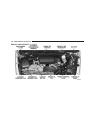
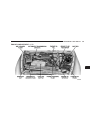
Airbag System Components
The airbag system consists of the following:
• Airbag Control Module
• AIRBAG Readiness Light
• Driver Airbag
The Window Airbag System, on vehicles equipped,
consists of the following:
• AIRBAG Readiness Light (shared with the front airbag
system)
• Window Bags Above the Side Windows.
• Passenger Airbag
• Airbag Control Module (shared with the front airbag
system)
• Steering Wheel and Column
• Side impact sensors
• Instrument Panel
• Interconnecting Wiring
• Crash Sensor
How The Airbag System Works
• Interconnecting Wiring
• The airbag control module determines if a frontal
collision is severe enough to require the airbags to
inflate.
• Knee Impact Bolsters
• Passenger Side Frontal Airbag ON/OFF Switch (Standard Cab Vehicles Only)
• The airbag control module will not detect roll over, or
rear collisions.
THINGS TO KNOW BEFORE STARTING YOUR VEHICLE
• The airbag control module also monitors the readiness
of the electronic parts of the system whenever the
ignition switch is in the START or RUN positions.
These include all of the items listed above except the
knee bolsters, the instrument panel, and the steering
wheel and column. If the key is in the 9Off9 position, in
the ACC position or not in the ignition, the airbags are
not on and will not inflate
• The airbag control module also turns on the AIR BAG
light in the instrument panel for 6 to 8 seconds when
the ignition is first turned on, then turns the light off.
49
• If it detects a malfunction in any part of the
system, it turns on the light either momentarily or continuously. The instrument cluster
will flash the seat belt indicator if it detects a fault with
the airbag indicator.
WARNING!
Ignoring the AIR BAG light in your instrument
panel could mean you won’t have the airbags to
protect you in a collision. If the light does not come
on, stays on after you start the vehicle, or if it comes
on as you drive, have the airbag system checked
right away.
2
50
THINGS TO KNOW BEFORE STARTING YOUR VEHICLE
• When the airbag control module detects a collision
requiring the airbags, it signals the inflator units. A
large quantity of nontoxic gas is generated to inflate
the airbags. The airbag covers separate and fold out of
the way as the airbags inflate to their full size. The
airbags fully inflate in milliseconds. This is less time
than it takes you to blink your eyes. The airbags then
quickly deflate while helping to restrain the driver and
front passenger. The driver’s front airbag deflates
through vents towards the instrument panel. The
passenger’s front airbag is deflated through vent holes
in the sides of the airbag. In this way the airbags do
not interfere with your control of the vehicle.
• The knee impact bolsters help protect the knees and
position you for the best interaction with the front
airbag.
Passenger Airbag On/Off Switch – (Standard Cab
Vehicles Only)
The passenger front airbag is to be turned off only if the
passenger:
• is an infant (less than 1 year old) who must ride in the
front seat because there is no rear seat, because the rear
seat is too small for a rear-facing infant restraint or
THINGS TO KNOW BEFORE STARTING YOUR VEHICLE
because the infant has a medical condition which
makes it necessary for the driver to be able to see the
infant,
• is a child, age 1 to 12 who must ride in the front seat
because there is no rear seat, because there is no rear
seat position available, or because the child has a
medical condition which makes it necessary for the
driver to be able to see the child,
• has a medical condition which makes passenger airbag
inflation (deployment) a greater risk for the passenger
than the risk of hitting the dashboard (instrument
panel) or windshield in a crash.
51
WARNING!
Whenever an airbag is turned off, even a lap/
shoulder belted passenger may hit their head, neck,
or chest on the dashboard (instrument panel) or
windshield in a crash. This may result in serious
injury or death.
To Shut Off the Passenger Airbag (Standard Cab Vehicles Only)
Place the ignition key in the Passenger Airbag On/Off
Switch, push the key in and turn clockwise, and remove
the key from the switch. This will shut off the passenger
side airbag. The “Off” light near the switch will illuminate when the ignition switch is turned to the ON
position.
2
52
THINGS TO KNOW BEFORE STARTING YOUR VEHICLE
To Turn On the Passenger Airbag (Standard Cab Vehicles Only)
If you do have a collision which deploys the airbags, any
or all of the following may occur:
Place the ignition key in the Passenger Airbag On/Off
Switch, push the key in and turn counterclockwise, and
remove the key from the switch. This will turn on the
passenger airbag. The “Off” light near the switch will be
off when the ignition switch is turned to the ON position.
• The nylon airbag material may sometimes cause abrasions and/or skin reddening to the driver and front
passenger as the airbags deploy and unfold. The
abrasions are similar to friction rope burns or those
you might get sliding along a carpet or gymnasium
floor. They are not caused by contact with chemicals.
They are not permanent and normally heal quickly.
However, if you haven’t healed significantly within a
few days, or if you have any blistering, see your doctor
immediately.
If A Deployment Occurs
The airbag system is designed to deploy when the air bag
control module detects a moderate-to-severe frontal collision, and then immediately to deflate.
NOTE: A frontal collision that is not severe enough to
need airbag protection will not activate the system. This
does not mean something is wrong with the airbag
system.
• As the airbags deflate you may see some smoke-like
particles. The particles are a normal by-product of the
process that generates the nontoxic gas used for airbag
inflation. These airborne particles may irritate the skin,
eyes, nose, or throat. If you have skin or eye irritation,
rinse the area with cool water. For nose or throat
THINGS TO KNOW BEFORE STARTING YOUR VEHICLE
irritation, move to fresh air. If the irritation continues,
see your doctor. If these particles settle on your
clothing, follow the garment manufacturer’s instructions for cleaning.
• It is not advisable to drive your vehicle after the
airbags have deployed. If you are involved in another
collision, the airbags will not be in place to protect you.
WARNING!
Deployed airbags can’t protect you in another collision. Have the airbags replaced by an authorized
dealer as soon as possible.
53
Window Airbags Supplemental Restraint System
(SRS)—If Equipped
The window airbag control module determines if a side
collision is severe enough to require the side airbags to
inflate. The window airbag control module will not
detect roll over, front or rear collisions.
The airbag control module monitors the readiness of the
electronic parts of the system whenever the ignition
switch is in the 9START9 or 9RUN9 positions. These
include all of the items listed above. The airbag control
module also turns on the AIRBAG light in the instrument
panel for 6 to 8 seconds when the ignition is first turned
on as a diagnostic or system check, then turns the light
off. If it detects a malfunction in any part of the system,
it turns on the light either momentarily or continuously.
The side (window) impact SRS Airbags are designed to
activate only in certain side collisions. When the airbag
control module detects a collision requiring the window
2
54
THINGS TO KNOW BEFORE STARTING YOUR VEHICLE
bags to inflate, it signals the inflators on the crash side of
the vehicle. A quantity of nontoxic gas is generated to
inflate the window bag. The inflating window bag
pushes the side pillar molding out of the way and covers
the window. The airbag inflates in about 30 milliseconds
(about one-quarter of the time it takes to blink your eyes)
with enough force to injure you if you are not belted and
seated properly, or if items are positioned in the area
where the window bag inflates. This especially applies to
children. The window bag is only about 3 1⁄2 inches (8.9
cm) thick when it is inflated.
Enhanced Accident Response System
If the airbags deploy after an impact and the electrical
system remains functional, vehicles equipped with
power door locks will unlock automatically. In addition,
approximately 10 seconds after the vehicle has stopped
moving, the interior lights will light until the ignition
switch is turned off.
Maintaining Your Airbag Systems
WARNING!
• Modifications to any part of the airbag system
could cause it to fail when you need it. You could
be injured because the airbags are not there to
protect you. Do not modify the components or
wiring, including adding any kind of badges or
stickers to the steering wheel hub trim cover or
the upper right side of the instrument panel. Do
not modify the front bumper, vehicle body structure, or frame.
• You need proper knee impact protection in a
collision. Do not mount or locate any aftermarket
equipment on or behind the knee bolster.
• It is dangerous to try to repair any part of the
airbag system yourself. Be sure to tell anyone who
works on your vehicle that it has airbags.
THINGS TO KNOW BEFORE STARTING YOUR VEHICLE
55
Airbag Light
You will want to have the airbags ready to inflate for your
protection in an impact. While the airbag system is
designed to be maintenance free, if any of the following
occurs, have an authorized dealer service the system
promptly:
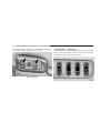
NOTE: If the speedometer, tachometer or any engine
related gauges are not working, the airbag control module may also be disabled. The airbags may not be ready
to inflate for your protection. Promptly check fuse numbers 52 and 53 in the fuse and relay center. See your
dealer if the fuse is good.
• The airbag light does not come on or flickers during
the 6 to 8 seconds when the ignition switch is first
turned on.
Child Restraint
Everyone in your vehicle needs to be buckled up all the
time — babies and children, too. Every state in the United
States and all Canadian provinces require that small
children ride in proper restraint systems. This is the law,
and you can be prosecuted for ignoring it.
• The light remains on or flickers after the 6 to 8 second
interval.
• The light flickers or comes on and remains on while
driving.
Children 12 years and under should ride properly buckled up in a rear seat, if available. According to crash
statistics, children are safer when properly restrained in
the rear seats rather than in the front.
2
56
THINGS TO KNOW BEFORE STARTING YOUR VEHICLE
WARNING!
In a collision, an unrestrained child, even a tiny
baby, can become a missile inside the vehicle. The
force required to hold even an infant on your lap can
become so great that you could not hold the child, no
matter how strong you are. The child and others
could be badly injured. Any child riding in your
vehicle should be in a proper restraint for the child’s
size.
Infants and Small Children
There are different sizes and types of restraints for
children from newborn size to the child almost large
enough for an adult safety belt. Use the restraint that is
correct for your child:
• Safety experts recommend that children ride
rearward-facing in the vehicle until they are at least
one year old and weigh at least 20 lbs (9 kg). Two types
of child restraints can be used rearward-facing: infant
carriers and 9convertible9 child seats. Both types of
child restraints are held in the vehicle by the lap/
shoulder belt.
• The infant carrier is only used rearward-facing in the
vehicle. It is recommended for children who weigh up
to about 20 lbs (9 kg). 9Convertible9 child seats can be
used either rearward-facing or forward-facing in the
vehicle. Convertible child seats often have a higher
weight limit in the rearward-facing direction than
infant carriers do, so they can be used rearward-facing
by children who weigh more than 20 lbs (9 kg) but are
less than one year old.
• Rearward-facing child seats must NEVER be used in
the front seat of a vehicle with a front passenger airbag
THINGS TO KNOW BEFORE STARTING YOUR VEHICLE
unless the airbag is turned off. An airbag deployment
could cause severe injury or death to infants in this
position.
• Children who weigh more than 20 lbs (9 kg) and who
are older than one year can ride forward-facing in the
vehicle. Forward-facing child seats and convertible
child seats used in the forward-facing direction are for
children who weigh 20 to 40 lbs (9 to 18 kg) and who
are older than one year. These child seats are also held
in the vehicle by the lap/shoulder belt.
• The belt-positioning booster seat is for children weighing more than 40 lbs (18 kg), but who are still too small
to fit the vehicle’s seat belts properly. If the child
cannot sit with knees bent over the vehicle’s seat
cushion while the child’s back is against the seat back,
they should use a belt-positioning-booster seat. The
child and booster seat are held in the vehicle by the
lap/shoulder belt. (Some booster seats are equipped
57
with a front shield and are held in the vehicle by the
lap portion.) For further information refer to
www.seatcheck.org.
WARNING!
• Improper installation can lead to failure of an
infant or child restraint. It could come loose in a
collision. The child could be badly injured or
killed. Follow the manufacturer’s directions exactly when installing an infant or child restraint.
• A rearward facing child restraint should only be
used in a rear seat, or in the front seat if the
passenger’s front airbag is Off. If the airbag is left
On, a rearward facing child restraint in the front
seat may be struck by a deploying passenger
airbag which may cause severe or fatal injury to
the infant.
2
58
THINGS TO KNOW BEFORE STARTING YOUR VEHICLE
Here are some tips for getting the most out of your child
restraint:
• Before buying any restraint system, make sure that it
has a label certifying that it meets all applicable Safety
Standards. We also recommend that you make sure
that you can install the child restraint in the vehicle
where you will use it before you buy it.
• The restraint must be appropriate for your child’s
weight and height. Check the label on the restraint for
weight and height limits.
• Carefully follow the instructions that come with the
restraint. If you install the restraint improperly, it may
not work when you need it.
• The passenger seat belts are equipped with either
cinching latch plates or switchable seat belt retractors,
which are designed to keep the lap portion tight
around the child restraint so that it is not necessary to
use a locking clip.
If the seat belt has a cinching latch plate, pulling up on
the shoulder portion of the lap/shoulder belt will
tighten the belt. The cinching latch plate will keep the
belt tight, however, any seat belt system will loosen
with time, so check the belt occasionally and pull it
tight if necessary.
If the seat belt has a switchable retractor, it will have a
distinctive label: Pull the belt from the retractor until
there is enough to allow you to pass through the child
restraint and slide the latch plate into the buckle. Then
pull on the belt until it is all removed from the retractor.
Allow the belt to return to the retractor, pulling on the
excess webbing to tighten the lap portion about the child
restraint. Refer to the 9Automatic Locking Mode9 earlier
in this section.
THINGS TO KNOW BEFORE STARTING YOUR VEHICLE
• In the rear seat, you may have trouble tightening the
lap/shoulder belt on the child restraint because the
buckle or latch plate is too close to the belt path
opening on the restraint. Disconnect the latch plate
from the buckle and twist the short buckle-end belt
several times to shorten it. Insert the latch plate into
the buckle with the release button facing out.
• If the belt still can’t be tightened, or if pulling and
pushing on the restraint loosens the belt, disconnect
the latch plate from the buckle, turn the buckle
around, and insert the latch plate into the buckle
again. If you still can’t make the child restraint secure,
try a different seating position.
• Buckle the child into the seat according to the child
restraint manufacturer’s directions.
• When your child restraint is not in use, secure it in the
vehicle with the seat belt or remove it from the vehicle.
59
Do not leave it loose in the vehicle. In a sudden stop or
collision, it could strike the occupants or seat backs
and cause serious personal injury.
WARNING!
Improper installation can lead to failure of an infant
or child restraint. It could come loose in a collision.
The child could be badly injured or killed. Follow
the manufacturer’s directions exactly when installing an infant or child restraint.
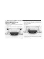
Lower Anchors and Tether for CHildren (LATCH)
Each vehicle is equipped with the child restraint anchorage system called LATCH, which stands for Lower
Anchors and Tether for CHildren. LATCH child restraint
anchorage systems are installed in the Standard Cab
passenger seat position and the Quad Cab rear seat
2
60
THINGS TO KNOW BEFORE STARTING YOUR VEHICLE
outboard positions and also feature tether strap anchorages, which must be used, located behind the seatback
(refer to Child Restraint Tether Anchor later in this
section).
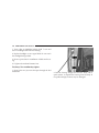
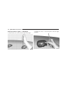
Identification dots are located above the standard cab
front seat lower anchorages as a guide for locating lower
anchors.
NOTE: For children riding in the front seat of a Standard Cab model refer to the “Passenger Airbag On/Off
Switch” located in this section.
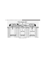
Standard Cab Passenger Seat
THINGS TO KNOW BEFORE STARTING YOUR VEHICLE
61
Child restraint systems having attachments designed to
connect to the lower anchorages are now available. Child
restraints having tether straps and hooks for connection
to the seatback tether anchorage have been available for
some time. In fact, many child restraint manufacturers
will provide add-on tether strap kits for some of their
older products.
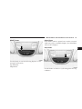
Because the lower anchorages are to be introduced to
passenger carrying vehicles over a period of years, child
restraint systems having attachments for those anchorages will continue to have features for installation in
vehicles using the lap or lap/shoulder belt. They will also
have tether straps, and you are urged to take advantage
of all of the available attachments provided with your
child restraint in any vehicle.
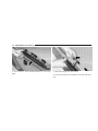
Quad Cab Outboard Seat
NOTE: If your child restraint seat is not LATCH compatible, install the restraint using the vehicle seat belting.
2
62
THINGS TO KNOW BEFORE STARTING YOUR VEHICLE
Installing the Child Restraint System
WARNING!
Do not install child restraint systems equipped with
LATCH attachments in the center position of a Quad
Cab model rear seat. The LATCH anchorages in this
seat are designed for the two outboard seating positions only. A child may be placed in the rear center
seating position of a Quad Cab model using the seat
belt and child tether anchorage. Failure to follow this
may result in serious or fatal injury.
We urge that you carefully follow the directions of the
manufacturer when installing your child restraint. Many,
but not all, restraint systems will be equipped with
separate straps on each side, with each having a hook or
connector and a means for adjusting the tension in the
strap. Forward-facing toddler restraints and some
rearward-facing infant restraints will also be equipped
with a tether strap, a hook and means for adjusting the
tension in the strap.
In general, you will first loosen the adjusters on the lower
straps and tether straps so that you can more easily attach
the hook or connector to the lower anchorages and tether
anchorages. Then tighten all three straps as you push the
child restraint rearward and downward into the seat.
Not all child restraint systems will be installed as we
have described here. Again, carefully follow the instructions that come with the child restraint system.
THINGS TO KNOW BEFORE STARTING YOUR VEHICLE
63
WARNING!
WARNING!
Improper installation of a child restraint to the
LATCH anchorages can lead to failure of an infant or
child restraint. The child could be badly injured or
killed. Follow the manufacturer’s directions exactly
when installing an infant or child restraint.
An incorrectly anchored tether strap could lead to
seat failure and injury to the child. In a collision, the
seat could come loose and allow the child to crash
into the inside of the vehicle or other passengers, or
even be thrown from the vehicle. Use only the
anchor positions directly behind the child seat to
secure a child restraint top tether strap. Follow the
instructions below. See your dealer for help if necessary.
Child Restraint Tether Anchor
Child restraints having tether straps and hooks for connection to tether anchors have been available for some
time. In fact, many child restraint manufacturers will
provide add-on tether strap kits for their older products.
Regular Cab models of Ram Pickups have two tether
anchorages, one each behind the front center and right
seats. Quad Cab models have three anchorages, one
behind each of the rear seats.
2
64
THINGS TO KNOW BEFORE STARTING YOUR VEHICLE
Tether Anchorage Points at the Right and Center
Front Seat (Regular Cab - All Seats)
1. Place the child restraint on the seat and adjust the
tether strap so that it will reach over the seat back under
the head restraint to the tether anchor directly behind the
seat.
2. Lift the cover (if so equipped), and attach the hook to
the square opening in the sheet metal.
3. Install the child restraint and remove the slack in the
tether strap according to the manufacturer’s instructions.
Regular Cab With Any Bench Seat
THINGS TO KNOW BEFORE STARTING YOUR VEHICLE
65
Multiple Child Restraint Installation Sequence (Quad Cab Rear Seats)
3. Pass each tether strap hook under the head restraint
and through the loop of webbing behind the child seat.
1. Obtain tether straps by raising the head restraints and
reaching between the rear glass and rear seat. The tether
strap may be retained with an elastic band. Accessibility
to the tether strap is greatly improved by raising the seat
cushion to the “up” position. Remove the elastic before
use.
4. Route each tether strap to the anchor behind the center
seat, and attach the hooks to the metal ring.
2. Place a child restraint on each outboard rear seat and
adjust the tether strap so that it will reach under the head
restraint to the tether anchor directly behind the seat and
then to the anchor directly behind the center rear seat.
5. Place a child restraint on the center rear seat and
adjust the tether strap so that it will reach under the head
restraint to the tether anchor directly behind the seat and
to the anchor directly behind the right seat.
6. Install each child restraint and remove the slack in the
tether strap according to the child restraint manufacturer’s instructions.
2
66
THINGS TO KNOW BEFORE STARTING YOUR VEHICLE
Multiple Child Restraints
THINGS TO KNOW BEFORE STARTING YOUR VEHICLE
Children Too Large for Booster Seats
Children who are large enough to wear the shoulder belt
comfortably, and whose legs are long enough to bend
over the front of the seat when their back is against the
seat back should use the lap/shoulder belt in a rear seat.
• Make sure that the child is upright in the seat.
• The lap portion should be low on the hips and as snug
as possible.
• Check belt fit periodically. A child’s squirming or
slouching can move the belt out of position.
If the shoulder belt contacts the face or neck, move the
child closer to the center of the vehicle. Never allow a
child to put the shoulder belt under an arm or behind
their back.
67
ENGINE BREAK-IN RECOMMENDATIONS
A long break-in period is not required for the engine in
your new vehicle. Drive moderately during the first 300
miles (500 km). After the initial 60 miles (100 km), speeds
up to 50 or 55 mph (80 or 90 km/h) are desirable. While
cruising, brief full-throttle acceleration, within the limits
of local traffic laws, contributes to a good break-in.
Avoid wide open throttle acceleration in low gear.
The engine oil installed in the engine at the factory is a
high quality, energy conserving type lubricant. Oil
changes should be consistent with the anticipated climatic conditions under which vehicle operation will
occur. The recommended viscosity and quality grades are
discussed in Section 7 under Maintenance Procedures,
Engine Oil.
NON-DETERGENT OR STRAIGHT MINERAL OILS
MUST NEVER BE USED.
2
68
THINGS TO KNOW BEFORE STARTING YOUR VEHICLE
A new engine may consume some oil during its first few
thousand miles of operation. This is a normal part of the
break-in and is not an indication of difficulty.
CAUTION!
• During the first 500 miles (805 km) your new
vehicle is driven, do not tow a trailer. Doing so
may damage your vehicle.
• Limit your speed to 50 mph (80 km/h) during the
first 500 miles (805 km) of towing.
SAFETY TIPS
Transporting Passengers
This vehicle is designed to carry passengers in the cab
only. For safety reasons, NEVER TRANSPORT PASSENGERS IN THE CARGO AREA.
WARNING!
It is extremely dangerous to ride in a cargo area,
inside or outside of a vehicle. In a collision, people
riding in these areas are more likely to be seriously
injured or killed.
Do not allow people to ride in any area of your
vehicle that is not equipped with seats and seat belts.
Be sure everyone in your vehicle is in a seat and
using a seat belt properly.
THINGS TO KNOW BEFORE STARTING YOUR VEHICLE
Lock Your Vehicle
Always remove the keys from the ignition and lock all
doors when leaving the vehicle unattended, even in your
own driveway or garage. Try to park your vehicle in a
well-lighted area and never invite theft by leaving articles of value exposed.
Exhaust Gas
WARNING!
Exhaust gases contain carbon monoxide, a potentially toxic gas that by itself is colorless and odorless.
To avoid inhaling these gases, the following precautions should be observed:
• Do not run the engine in a closed garage or in confined
areas any longer than needed to move your vehicle in
or out of the area.
69
• If it is necessary to sit in a parked vehicle with the
engine running for more than a short period, adjust
your climate control system to force outside air into
the vehicle. Set the blower at high speed and the
controls in any position except OFF or MAX A/C.
• The best protection against carbon monoxide entry
into the vehicle body is a properly maintained engine
exhaust system.
Be aware of changes in the sound of the exhaust system;
exhaust fumes detected inside the vehicle; or damage to
the underside or rear of the vehicle. Have a competent
mechanic inspect the complete exhaust system and adjacent body areas for broken, damaged, deteriorated or
mispositioned parts. Open seams or loose connections
could permit exhaust fumes to seep into the passenger
compartment. In addition, inspect the exhaust system
each time the vehicle is raised for lubrication or oil
change. Replace or adjust as required.
2
70
THINGS TO KNOW BEFORE STARTING YOUR VEHICLE
Safety Checks You Should Make Inside The Vehicle
Seat Belts
Inspect the belt system periodically, checking for cuts,
frays and loose parts. Damaged parts must be replaced
immediately. Do not disassemble or modify the system.
Seat belt assemblies must be replaced after an accident if
they have been damaged (bent retractor, torn webbing,
etc.) or if the front airbags have deployed. If there is any
question regarding belt or retractor condition, replace the
belt.
Airbag Light
The light should come on and remain on for 6 to 8
seconds as a bulb check when the ignition switch is first
turned ON. If the light is not lit during starting, see you
authorized dealer. If the light stays on, flickers or comes
on while driving, have the system checked by an authorized dealer. If there is a problem with the airbag light the
seatbelt light will flash.
Safety Checks You Should Make Outside The
Vehicle
Tires
Examine tires for tread wear or uneven wear patterns.
Check for stones, nails, glass or other objects lodged in
the tread.
Inspect for tread cuts or sidewall cracks. Check wheel
nuts for tightness and tires for proper pressure.
Lights
Check the operation of all exterior lights. Check turn signal
and high beam indicator lights on the instrument panel.
Door Latches
Check for positive closing, latching and locking.
Fluid Leaks
Check area under vehicle after overnight parking for fuel,
water, oil, or other fluid leaks. Also, if fuel fumes are
detected the cause should be located and corrected.
UNDERSTANDING THE FEATURES OF YOUR VEHICLE
CONTENTS
m Mirrors . . . . . . . . . . . . . . . . . . . . . . . . . . . . . . .75
▫ Inside Mirror . . . . . . . . . . . . . . . . . . . . . . . . .75
▫ Automatic Dimming Mirror— If Equipped . . . .76
▫ Outside Mirrors . . . . . . . . . . . . . . . . . . . . . . .76
▫ Exterior Mirrors Folding Feature . . . . . . . . . . .77
▫ Electronic Power Mirrors — If Equipped . . . . . .77
▫ Electric Rear Window Defroster And Heated
Sideview Mirrors — If Equipped . . . . . . . . . . .78
▫ Trailer Towing Mirrors — If Equipped . . . . . . .79
3
m Hands–Free Communication (UConnect™) — If
Equipped . . . . . . . . . . . . . . . . . . . . . . . . . . . . .79
▫ Operation . . . . . . . . . . . . . . . . . . . . . . . . . . . .81
▫ Phone Call Features . . . . . . . . . . . . . . . . . . . .85
▫ Advanced Phone Connectivity . . . . . . . . . . . . .87
▫ UConnect™ System Features . . . . . . . . . . . . . .89
m Seats . . . . . . . . . . . . . . . . . . . . . . . . . . . . . . . . .91
▫ 40-20-40 Front Seat . . . . . . . . . . . . . . . . . . . . .92
▫ Reclining Seats . . . . . . . . . . . . . . . . . . . . . . . .93
72
UNDERSTANDING THE FEATURES OF YOUR VEHICLE
▫ Adjustable Head Restraints . . . . . . . . . . . . . . .93
▫ Fog Lights — If Equipped . . . . . . . . . . . . . . . 102
▫ Manual Rotary Lumbar Support
Adjustment — If Equipped . . . . . . . . . . . . . . .94
▫ Cargo Light . . . . . . . . . . . . . . . . . . . . . . . . . 103
▫ Power Seats — If Equipped . . . . . . . . . . . . . . .95
▫ Heated Seats — If Equipped . . . . . . . . . . . . . .96
m To Open And Close The Hood . . . . . . . . . . . . . .97
m Lights . . . . . . . . . . . . . . . . . . . . . . . . . . . . . . . .99
▫ Interior Lights . . . . . . . . . . . . . . . . . . . . . . . .99
▫ Battery Saver . . . . . . . . . . . . . . . . . . . . . . . . 100
▫ Headlamp Delay — If Equipped . . . . . . . . . . 101
▫ Headlights, Parking Lights, Panel Lights . . . . . 101
▫ Daytime Running Lights (Canada And Fleet
Vehicles Only) . . . . . . . . . . . . . . . . . . . . . . . 102
▫ Lights-On Reminder . . . . . . . . . . . . . . . . . . . 102
m Multifunction Control Lever . . . . . . . . . . . . . . . 103
▫ Turn Signals . . . . . . . . . . . . . . . . . . . . . . . . . 103
▫ Passing Light . . . . . . . . . . . . . . . . . . . . . . . . 104
▫ High Beam / Low Beam Select Switch . . . . . . 104
▫ Windshield Wipers . . . . . . . . . . . . . . . . . . . . 105
▫ Windshield Washers . . . . . . . . . . . . . . . . . . . 106
m Tilt Steering Column . . . . . . . . . . . . . . . . . . . . 107
m Driver Adjustable Pedals — If Equipped . . . . . . 108
▫ Adjustment . . . . . . . . . . . . . . . . . . . . . . . . . 108
m Electronic Speed Control — If Equipped . . . . . . 109
▫ To Activate . . . . . . . . . . . . . . . . . . . . . . . . . . 109
UNDERSTANDING THE FEATURES OF YOUR VEHICLE
73
▫ To Set At A Desired Speed . . . . . . . . . . . . . . . 110
▫ Average Fuel Economy (AVG ECO) . . . . . . . . 116
▫ To Deactivate . . . . . . . . . . . . . . . . . . . . . . . . 110
▫ Distance To Empty (DTE) . . . . . . . . . . . . . . . 116
▫ To Resume Speed . . . . . . . . . . . . . . . . . . . . . 110
▫ Trip Odometer (ODO) . . . . . . . . . . . . . . . . . . 116
▫ To Vary The Speed Setting . . . . . . . . . . . . . . . 111
▫ Elapsed Time (ET) . . . . . . . . . . . . . . . . . . . . . 117
▫ To Accelerate For Passing . . . . . . . . . . . . . . . 112
▫ C/T Button . . . . . . . . . . . . . . . . . . . . . . . . . 117
m Overhead Console— If Equipped . . . . . . . . . . . 113
▫ Automatic Compass Calibration . . . . . . . . . . . 117
▫ Courtesy/Reading Lights . . . . . . . . . . . . . . . . 113
▫ Manual Compass Calibration . . . . . . . . . . . . . 118
m Overhead Console With Compass/Temperature
Mini-Trip Computer — If Equipped . . . . . . . . . . 114
▫ To Put Into a Calibration Mode . . . . . . . . . . . 118
▫ US/M Button . . . . . . . . . . . . . . . . . . . . . . . . 114
▫ Reset Button . . . . . . . . . . . . . . . . . . . . . . . . . 115
▫ Global Reset . . . . . . . . . . . . . . . . . . . . . . . . . 115
▫ Step Button . . . . . . . . . . . . . . . . . . . . . . . . . 115
▫ Outside Temperature . . . . . . . . . . . . . . . . . . . 119
m Garage Door Opener — If Equipped . . . . . . . . . 120
▫ Programming Homelink . . . . . . . . . . . . . . . . 121
▫ Canadian Programming/Gate Programming . . 123
▫ Using Homelink . . . . . . . . . . . . . . . . . . . . . . 124
3
74
UNDERSTANDING THE FEATURES OF YOUR VEHICLE
▫ Erasing Homelink Buttons . . . . . . . . . . . . . . . 124
m Storage . . . . . . . . . . . . . . . . . . . . . . . . . . . . . . 129
▫ Reprogramming a Single Homelink Button . . . 125
▫ Center Storage Compartment — If Equipped . . 129
▫ Security . . . . . . . . . . . . . . . . . . . . . . . . . . . . 125
▫ Storage And Seats — If Equipped . . . . . . . . . . 130
m Electrical Power Outlets . . . . . . . . . . . . . . . . . . 126
m Fold Flat Load Floor — If Equipped . . . . . . . . . 130
m Cigar Lighter And Ash Receiver . . . . . . . . . . . . 127
▫ Fold Flat Load Floor — If Equipped . . . . . . . . 130
m Cupholders . . . . . . . . . . . . . . . . . . . . . . . . . . . 128
m Pickup Box . . . . . . . . . . . . . . . . . . . . . . . . . . . 133
▫ Front Instrument Panel Cupholders —
Automatic Transmission Only . . . . . . . . . . . . 128
m Slide-In Campers . . . . . . . . . . . . . . . . . . . . . . . 135
▫ Rear Cupholder — Quad Cab — If
Equipped . . . . . . . . . . . . . . . . . . . . . . . . . . . 128
▫ Camper Applications . . . . . . . . . . . . . . . . . . . 135
m Easy-Off Tailgate . . . . . . . . . . . . . . . . . . . . . . . 135
UNDERSTANDING THE FEATURES OF YOUR VEHICLE
75
MIRRORS
Inside Mirror
The mirror should be adjusted to center on the view
through the rear window.
Annoying headlight glare can be reduced by moving the
small control under the mirror to the night position
(toward rear of vehicle). The mirror should be adjusted
while set in the day position (toward windshield).
3
76
UNDERSTANDING THE FEATURES OF YOUR VEHICLE
Automatic Dimming Mirror— If Equipped
This mirror automatically adjusts for annoying headlight
glare from vehicles behind you. You can turn the feature
on or off by pressing the button at the base of the mirror.
A light in the button will indicate when the dimming
feature is activated.
CAUTION!
To avoid damage to the mirror during cleaning,
never spray any cleaning solution directly onto the
mirror. Apply the solution onto a clean cloth and
wipe the mirror clean.
Outside Mirrors
To receive maximum benefit, adjust the outside mirror(s)
to center on the adjacent lane of traffic with a slight
overlap of the view obtained on the inside mirror.
UNDERSTANDING THE FEATURES OF YOUR VEHICLE
WARNING!
Vehicles and other objects seen in a right side convex
mirror will look smaller and farther away than they
really are. Relying too much on your right side
convex mirror could cause you to collide with another vehicle or other object. Use your inside mirror
when judging the size or distance of a vehicle seen
in the right side convex mirror. Some vehicles will
not have a convex right side mirror.
Exterior Mirrors Folding Feature
All exterior mirrors are hinged and may be moved either
forward or rearward to resist damage. The hinges have
three detent positions; full forward, full rearward, and
normal.
77
Electronic Power Mirrors — If Equipped
3
78
UNDERSTANDING THE FEATURES OF YOUR VEHICLE
The controls for the power mirrors are located on the
driver’s door trim panel.
Set the top switch to the left or right for the left or right
mirror, and set it to the center off position to prevent
accidentally moving a mirror when you are finished
adjusting the mirror. To adjust a mirror, select left or right
with the top switch, and press one of the four arrows for
the direction you want the mirror to move.
Electric Rear Window Defroster and Heated
Sideview Mirrors — If Equipped
The Electric Rear Window Defroster and Heated
side view mirrors are activated by pressing the
heated grid button, located on the Climate Control panel,
with the ignition On. Turning Off the ignition will
deactivate the Electric Rear Window Defroster and
Heated side view mirrors feature. These features also
turn off after activation, when 15 minutes have elapsed.
To reactivate, simply press the button again.
UNDERSTANDING THE FEATURES OF YOUR VEHICLE
79
Trailer Towing Mirrors — If Equipped
These mirrors are designed with an adjustable mirror
head to provide a greater vision range when towing
extra-wide loads. To change position inboard or outboard, the mirror head should be rotated (flipped Out or
In). A small blindspot mirror is integrated onto the main
mirror surface.
3
HANDS–FREE COMMUNICATION (UConnect™) —
IF EQUIPPED
UConnect™ is a voice-activated, hands-free, in-vehicle
communications system. UConnect™; allows you to dial
your cellular phone using simple voice commands (e.g.,
80
UNDERSTANDING THE FEATURES OF YOUR VEHICLE
“Call” or “Dial”). Your cellular phone’s audio is transmitted through your vehicle’s stereo system; the system
will automatically mute your radio before receiving or
sending a call.
UConnect™ allows you to transfer calls between the
system and your cellular phone as you enter or exit your
vehicle, and enables you to mute the system’s microphone for private conversations.
The UConnect™; phone book enables you to store up to
32 names and four numbers per name. This system is
driven through your Bluetooth™ Hands-Free Profile
cellular phone. UConnect™ features Bluetooth™ technology - the global standard that enables different electronic
devices to connect to each other without wires or a
docking station, so UConnect™ works no matter where
you stow your cellular phone (be it your purse, pocket, or
briefcase). UConnect™ allows up to seven cellular
phones to be linked to the system, and it is available in
English, French, or Spanish formats (as equipped).
The rearview mirror contains the microphone for the
system and the control buttons that will enable you to
access the system. The diagram below shows the mirror
with the appropriate buttons. Individual button behavior
is discussed in the “Operation” Section.
UNDERSTANDING THE FEATURES OF YOUR VEHICLE
The UConnect™ system can be used with any Hands
Free Profile certified Bluetooth™ cellular phone. If your
cellular phone has a different profile (i.e. headset profile),
you will not be able to use any UConnect™ features.
The UConnect™ system is fully integrated into your
vehicle, including your vehicle’s stereo system. All voice
prompts as well as the other party’s voice in a conversation will be played over your vehicle’s stereo system. The
volume of the UConnect™ system can be controlled
through your normal stereo controls.
The radio display will be used for visual prompts from
the UConnect™ system such as caller ID.
Operation
Voice commands can be used in the operation of the
UConnect™ system and to navigate through the UConnect™ menu structure. Voice commands should be given
after each UConnect™ system prompt. You will be
81
prompted for a specific command and then guided
through the available options. There are two ways to give
commands to the UConnect™ system:
• You can say 9Dial9 at the 9Ready9 prompt. When
prompted for the phone number you wish to dial, say
the phone number (9123 456 78909).
Pairing a Cellular Phone to the UConnect™ System
To begin using your UConnect™ system, you must pair
your compatible Bluetooth™ enabled cellular phone. To
complete the registration process, you will need to reference your cellular phone owner’s manual.
• Press the ’Phone’ button to begin.
• After the 9Ready9 prompt, say 9Setup9.
• When prompted, say “ Phone Pairing”.
3
82
UNDERSTANDING THE FEATURES OF YOUR VEHICLE
• You will be asked to say a four-digit pin number into
the UConnect™ system which you will later need to
enter into your cellular phone during the cellular
phone pairing process. You can enter any four-digit
pin number. You will not need to remember this pin
number after the initial registration process.
• The UConnect™ system will then prompt you to begin
the cellular phone pairing process on your cellular
phone. Please see your cellular phone user’s manual
for instructions on how to complete this step.
• For identification purposes, you will be prompted to
give the UConnect™ system a name for your cellular
phone. Each cellular phone that is paired should be
given a unique phone name.
• You will then be asked to give your cellular phone a
priority level between 1 and 7, 1 having the highest
priority. You can connect up to seven cellular phones
to your UConnect™ system and the priority allows the
UConnect™ system to know which cellular phone to
use if multiple cellular phones are in the vehicle at the
same time. For example, if a priority 3 and priority 5
cellular phone are both in the vehicle, the UConnect™
system will use the priority 3 cellular phone when you
make a call. You can select to use a lower priority
cellular phone at any time.
Making a Phone Call Using Digit Dialing
• Press the ’Phone’ button to begin.
• After the 9Ready9 prompt, say 9Dial9 or 9Call9 followed
by the phone number you wish to dial. For example,
you can say 9Dial” wait for ready prompt 123 456 7890.
The phone number that you enter must be a valid
length.
Making a Phone Call Using Your UConnect™
Phonebook
• Press the “Phone” button to begin.
UNDERSTANDING THE FEATURES OF YOUR VEHICLE
83
• After the 9Ready9 prompt, say 9Dial9 or 9Call9 wait for
the ready prompt followed by the name and designation of a phonebook entry that you wish to dial. For
example, you can say 9Call John Doe Work9.
After you are finished adding an entry into the phonebook, you will be given the opportunity to add more
phone numbers to the current entry or to return to the
main menu.
Add Names to Your UConnect™ Phonebook
The UConnect™ system will allow you to enter up to 32
names into the phonebook with each name having up to
four associated phone numbers and designations.
• Press the “Phone” button to begin.
• After the 9Ready9 prompt, say 9Phonebook New Entry9.
• Or, After the 9Ready9 prompt, say “Phonebook”.
• When prompted, say “New Entry”.
• When prompted, say the name of the new entry.
• Next, enter the number designation (e.g. “Home”,
“Work”, “Mobile”, or “Pager”). This will allow you to
have multiple numbers for each phonebook entry.
• Recite the phone number for the phonebook entry that
you are adding.
Edit Entries in the UConnect™ Phonebook
• Press the ’Phone’ button to begin.
• After the 9Ready9 prompt, say 9Phonebook Edit9.
• You will then be asked for the name of the phonebook
entry that you wish to edit.
• Next, choose the number designation that you wish to
edit. The choices are home, work, mobile, or pager.
• Recite the new phone number for the phonebook entry
that you are editing.
3
84
UNDERSTANDING THE FEATURES OF YOUR VEHICLE
After you are finished editing an entry in the phonebook,
you will be given the opportunities to edit another entry
in the phonebook, call the number you just edited, or
return to the main menu.
phonebook from which you can choose. To select one
of the entries from the list, press the 9Voice Recognition9 button while the UConnect™ system is playing
the desired entry and say 9Delete9.
Phonebook edit can be used to add another phone
number to a name entry that already exists in the
phonebook. For example, the entry John Doe may have a
mobile and a home number, but you can add John Doe’s
work number later through phonebook edit.
• After you enter the name, the UConnect™ system will
ask you if you wish to delete the home, work, mobile,
or pager number for this entry.
Delete Entries in the UConnect™ Phonebook
• Press the ’Phone’ button to begin.
• After the 9Ready9 prompt, say 9Phonebook Delete9.
• After you enter the phonebook delete menu, you will
then be asked for the name of the phonebook entry
that you wish to delete. You can either say the name of
a phonebook entry that you wish to delete or you can
say 9List Names9 to hear a list of the entries in the
Delete All Entries in the UConnect™ Phonebook
• Press the ’Phone’ button to begin.
• After the 9Ready9 prompt, say 9Phonebook Delete All9.
• The UConnect™ system will ask you to verify that you
wish to delete all the entries from the phonebook.
• After confirmation, the phonebook entries will be
deleted.
UNDERSTANDING THE FEATURES OF YOUR VEHICLE
List All Names in the UConnect™ Phonebook
• Press the ’Phone’ button to begin.
• After the 9Ready9 prompt, say 9Phonebook List
Names9.
• The UConnect™ system will play the names of all the
phonebook entries.
• To call one of the names in the list, press the ’Voice
Recognition’ button during the playing of the desired
name and say 9Call9.
• The UConnect™ system will then prompt you as to
number designation you wish to call.
• The selected number will be dialed.
85
Phone Call Features
The following feature(s) can be accessed through the
UConnect™ system if the feature(s) are available on your
cellular service plan. For example, if your cellular service
plan provides three-way calling, this feature can be
accessed through the UConnect™ system.
Answer or Reject an Incoming Call - No Call
Currently in Progress
When you receive a call on your cellular phone, the
UConnect™ system will interrupt the stereo audio and
will ask if you would like to answer the call by pressing
the ’Phone’ button. Press the ’Phone’ button to answer
the call. To reject the call, press the ’Phone’ button until
you hear a single beep indicating that the incoming call
was rejected.
3
86
UNDERSTANDING THE FEATURES OF YOUR VEHICLE
Answer or Reject an Incoming Call - Call
Currently in Progress
If a call is currently in progress and you have another
incoming call, press the ’Phone’ button to place the
current call on hold and answer the incoming call. To
reject the incoming call, you can disregard the call and
continue with your current conversation.
Making a Second Call while Current Call in
Progress
To make a second call while you are currently in a call,
press the ’Voice Recognition’ button and say 9Dial9 or
9Call9 followed by the phone number or phonebook entry
you wish to call. The first call will be on hold while the
second call is in progress.
Putting a Call on Hold and Retrieving a Call from
Hold
To put a call on hold, press the ’Phone’ button until you
hear a single beep which will indicate that the call has
been placed on hold. To bring the call back from hold,
press the ’Phone’ button.
Toggling Between Two Calls
If two calls are in progress (one active and one on hold),
press the ’Phone’ button until you hear a single beep
indicating that the active and hold status of the two calls
have switched. Only one call can be placed on hold at one
time.
Conference Call
When two calls are in progress (one active and one on
hold), press the ’Phone’ button until you hear a double
beep indicating that the two calls have been joined into
one conference call.
UNDERSTANDING THE FEATURES OF YOUR VEHICLE
Three-Way Calling
To initiate three-way calling, press the ’Voice Recognition’ button while a call is in progress and make a second
phone call. When the second call is established, press the
’Phone’ button until you hear a double beep indicating
that the two calls have been joined into one conference
call.
Call Termination
To end a call in progress, press the ’Phone’ button. All
calls in progress will be terminated.
Phone Redial
• Press the ’Phone’ button to begin.
• After the 9Ready9 prompt, say 9Redial9.
• The UConnect™ system will call the last number that
was dialed on your cellular phone. This may not be the
last number dialed by your UConnect™ system.
87
Advanced Phone Connectivity
Transferring an Active Call between the
UConnect™ System and Your Cellular Phone
The UConnect™ system allows ongoing calls to be transferred to your cellular phone or to the UConnect™
system without terminating the call. To transfer an ongoing call from your cellular phone to the UConnect™
system or vice versa, press the ’Voice Recognition’ button
and say 9Transfer Call9.
Delete Paired Cellular Phones
• Press the ’Phone’ button to begin.
• After the 9Ready9 prompt, say 9Setup9.
• When prompted, say “ Phone Pairing”.
• At the next prompt, say 9Delete9.
3
88
UNDERSTANDING THE FEATURES OF YOUR VEHICLE
• You will be asked to say the name of the phone that
you wish to delete. You can either say the name of the
phone that you wish to delete or you can say 9All9 to
delete all the phones.
• After the 9Ready9 prompt, say 9Setup List Phones9 and
the UConnect™ system will play the phone names of
all paired cellular phones in order from highest priority to lowest priority.
Connect or Disconnect the Connection between the
UConnect™ System and Your Cellular Phone
Your cellular phone can be paired with many different
electronic devices, but can only be actively 9connected9
with one electronic device at a time.
Select a Lower Priority Paired Cellular Phone
If you would like to connect or disconnect the Bluetooth™ connection between a paired cellular phone and
the UConnect™ system, follow the instruction described
in your cellular phone user’s manual.
• When prompted, say the phone name of the cellular
phone you wish to use, or say 9List Phones9 to hear a
list of all the phones that have been paired to your
UConnect™ system. To select a phone from the list,
press the ’Voice Recognition’ button and say 9Select9.
List Paired Cellular Phone Names
• Press the ’Phone’ button to begin.
• Press the ’Phone’ button to begin.
• After the 9Ready9 prompt, say 9Setup9.
• When prompted, say “Select Phone”.
UNDERSTANDING THE FEATURES OF YOUR VEHICLE
• The lower priority phone will only be used for the next
phone call. After that, the UConnect™ system will
return to using the highest priority phone in the
vehicle.
UConnect™ System Features
Barge In - Touch Tone Phone Inputs
You can use your UConnect™ system to access a voice
mail system, an automated service, or any other phone
number that you can dial with any phone. When calling
a number with your UConnect™ system that normally
requires you to enter in a touch-tone sequence on your
cellular phone keypad, you can push the ’Voice Recognition’ button and say the sequence you wish to enter
followed by 9Send9. For example, if required to enter your
pin number, you can press the ’Voice Recognition’ button
and say 93 7 4 6 Send9, or whatever you have made your
pin. This method can also be used in instances where you
89
are pressing a number on your keypad to navigate
through a menu structure or to enter a number for a
pager.
Barge In - Overriding Prompts
The ’Voice Recognition’ button can be used when you
wish to skip part of a prompt and issue your voice
recognition command immediately. For example, if a
prompt is playing 9Would you like to pair a phone, clear
a{9, you could press the ’Voice Recognition’ button and
say 9Pair A Phone9 to select that option without having to
listen to the rest of the voice prompt.
Language Selection
To change the language that the UConnect™ system is
using, press the ’Phone’ button and say the name of the
language you wish to switch to (English, Español, or
Français as equipped). After selecting one of the languages, all prompts and voice commands will be in the
selected language.
3
90
UNDERSTANDING THE FEATURES OF YOUR VEHICLE
Turning Confirmation Prompts On/Off
Turning confirmation prompts off will stop the system
from confirming your choices (e.g. the UConnect™ system will not repeat a phone number before you dial it).
• Press the ’Phone’ button to begin.
• After the 9Ready9 prompt, say 9Setup Confirmation9.
The UConnect™ system will play the current confirmation prompt status and you will be given the choice
to change it.
Low Signal, Battery Strength, and Roam
Notification
The UConnect™ system will provide notification to
inform you if your cellular phone is in roaming status,
has low signal strength, or has a low battery when you
are trying to place a phone call.
Dialing Using the Cellular Phone Keypad
You can dial a phone number with your cellular phone
keypad and still use the UConnect™ system. By dialing a
number with your paired Bluetooth™ cellular phone, the
audio will be played through your vehicle’s stereo system. The UConnect™ system will work the same as if
you dialed the number using voice recognition.
Mute/Unmute
When you mute the UConnect™ system, you will still be
able to hear the conversation coming from the other
party, but the other party will not be able to hear you. In
order to mute the UConnect™ system press the ’Voice
Recognition’ button and say 9Mute9. In order to unmute
the UConnect™ system; press the ’Voice Recognition’
button and say 9Unmute9.
UNDERSTANDING THE FEATURES OF YOUR VEHICLE
Help
If you need assistance at any prompt or if you want to
know what your options are at any prompt, say 9Help9.
The UConnect™ system will play all the options at any
prompt if you ask for help.
Cancel
At any prompt, you can say 9Cancel9 and you will be
returned to the previous menu.
Emergency Assistance
If you are in an emergency, say 9Dial Emergency9 or 9Call
Emergency9 and the UConnect™ system will instruct
your cellular phone to call 911.
Towing Assistance
If you need towing assistance, say 9Dial Towing Assistance9 or 9Call Towing Assistance9. Please refer to the
24-Hour Towing Assistance coverage details in the
DaimlerChrysler Motors Company 24-Hour Towing Assistance Program Guide.
91
SEATS
The seating options available in this truck are the result of
extensive customer research and evaluations.
WARNING!
It is extremely dangerous to ride in a cargo area,
inside or outside of a vehicle. In a collision, people
riding in these areas are more likely to be seriously
injured or killed.
Do not allow people to ride in any area of your
vehicle that is not equipped with seats and seat belts.
Be sure everyone in your vehicle is in a seat and
using a seat belt properly.
3
92
UNDERSTANDING THE FEATURES OF YOUR VEHICLE
40-20-40 Front Seat
Each outboard seat is independently adjustable forward
or backward and is equipped with a back recliner. The
manual seat adjustment handle is found at the front edge
of each seat cushion. Pull up on the handle and slide the
seat to get the most comfortable position.
WARNING!
Adjusting a seat while the vehicle is moving is
dangerous. The sudden movement of the seat could
cause you to lose control. The seat belt might not be
properly adjusted and you could be injured. Adjust
any seat only while the vehicle is parked.
As the name implies, the seat is divided into 3 segments.
The outboard seat portions are each 40% of the total
width of the seat. The back of the center portion (20%)
easily folds down to provide an armrest/center storage
compartment (if equipped).
UNDERSTANDING THE FEATURES OF YOUR VEHICLE
Reclining Seats
The recliner handle is on the outside of the seat cushion.
Pull up on the handle to release the seat back and adjust
for comfort.
93
WARNING!
You can be seriously, even fatally injured riding in a
seat with the seatback reclined. Do not ride with the
seatback reclined so that the shoulder belt is no
longer resting against your chest. If you ride in this
position, the shoulder harness will no longer be
restraining you. In a collision you could slide under
the seat belt and receive serious or fatal injuries.
Recline in a seat only when the vehicle is parked.
Adjustable Head Restraints
Head restraints can reduce the risk of whiplash injury in
the event of impact from the rear. Pull up or push down
on the restraints so that the upper edge is as high as
practical, at least to the level of the ears.
3
94
UNDERSTANDING THE FEATURES OF YOUR VEHICLE
To lower the head restraint, push in the button and then
push down on the head restraint.
Manual Rotary Lumbar Support Adjustment — If
Equipped
Rotating the lumbar control knob on the left side of the
driver’s seatback and on the right side of the passenger’s
seatback increases or decreases the lumbar support.
Lumbar Adjustment
UNDERSTANDING THE FEATURES OF YOUR VEHICLE
95
Power Seats — If Equipped
CAUTION!
Don’t put anything under a power seat. It may cause
damage to the seat controls.
3
Up, Down, Forward, and Rearward
The power seat controls are on the outboard side of the
front seat cushions. Three switches control the seat movement. The four-way switch in the center can be moved
forward or backwards to get the most comfortable position. The same switch can be moved up and down to
96
UNDERSTANDING THE FEATURES OF YOUR VEHICLE
control seat height. Change the seat angle by using the
two toggle switches, tilting it up or down.
Tilt Adjustment
Heated Seats — If Equipped
The heated seat switches are located in the instrument
panel under the climate controls. The engine must be
running for the heated seats to operate.
UNDERSTANDING THE FEATURES OF YOUR VEHICLE
Each heated seat switch has two settings (HI and LOW).
Press the switch once to obtain the desired heating
position and press a second time in the same direction to
turn the heated seats OFF. If you do not purposefully
turn the switch OFF, the heating element in the seat will
remain activated until the ignition is turned off. The
indicators on the switch will illuminate when the heated
seats are in the (HI or LOW) position. Flashing telltale
lights on the switch indicate that the Heated Seat system
needs servicing.
97
TO OPEN AND CLOSE THE HOOD
3
To open the hood, two latches must be released. First pull
the hood release lever located below the steering wheel at
the base of the instrument panel. Once the hood is
released you must reach into the opening beneath the
center of the grille and push up the latch to release the
safety catch before raising the hood.
98
UNDERSTANDING THE FEATURES OF YOUR VEHICLE
To prevent possible damage, do not slam the hood to
close it. Use a firm downward push at the front center of
the hood to ensure that both latches engage.
WARNING!
If the hood is not fully latched, it could fly up when
the vehicle is moving and block your forward vision.
Be sure all hood latches are latched fully before
driving.
UNDERSTANDING THE FEATURES OF YOUR VEHICLE
LIGHTS
99
Interior Lights
3
Courtesy/ dome lights are turned on when the front
doors are opened, when the dimmer control (rotating
wheel on the right side of the switch) is rotated to the
second upward detent position, or if equipped, when the
UNLOCK button is pressed on the key fob. Rotating the
dimmer control to the optional fully upward position will
100
UNDERSTANDING THE FEATURES OF YOUR VEHICLE
turn on the cargo light located on the back of the cab.
When a door is open and the interior lights are on,
rotating the dimmer control all the way down to the OFF
detent will cause all the interior lights to go out. This is
also known as the 9Party9 mode because it allows the
doors to stay open for extended periods of time without
discharging the vehicle’s battery.
The brightness of the instrument panel lighting can be
regulated by rotating the dimmer control up (brighter) or
down (dimmer). When the headlights are ON you can
supplement the brightness of the odometer, trip odometer, radio and overhead console by rotating the control
up until you hear a click. This feature is termed the
“Parade” mode and is useful when headlights are required during the day.
Battery Saver
To protect the life of your vehicle’s battery, Load Shedding is provided for both the interior and exterior lights.
If the ignition is off and any door is left ajar for 15
minutes or the dimmer control is rotated upwards for 15
minutes, the interior lights will automatically turn off.
If the headlamps remain on while the ignition is cycled
off, the exterior lights will automatically turn off after 5
minutes. After 5 minutes timeout, if the headlamp switch
is turned off and then turned on, the exterior lights will
automatically turn off after 15 minutes.
If the dimmer control is rotated to the cargo lamp
position with the ignition off, the cargo lamps will
automatically turn off after 15 minutes.
NOTE: Battery Saver mode is cancelled if the ignition is
ON.
UNDERSTANDING THE FEATURES OF YOUR VEHICLE
Headlamp Delay — If Equipped
To aid in your exit, your vehicle, if equipped, can be
programmed by your dealer with a headlamp delay that
will leave the headlamps on for 0, 30, 60, or 90 seconds.
This delay is initiated when the ignition is turned OFF
while the headlamp switch is on, and then the headlamp
switch is cycled off. The headlamps will remain on for 60
seconds. Headlamp delay can be cancelled by either
turning the headlamp switch ON then OFF or by turning
the ignition ON.
Headlights, Parking Lights, Panel Lights
When the headlight switch is rotated to the first
position, the parking lights, taillights, side marker
lights, license plate light and instrument panel
lights are all turned on. Rotating the headlight switch to
the first position will also turn on the cab top clearance
lights, flare lights, and tailgate lights if the vehicle is
equipped with these lights. The headlights will turn ON
when the switch is rotated to the second position. The
101
9LAMP OUT9 indicator will be illuminated in the instrument cluster if a defective bulb or wiring circuit is
detected for the headlamp system.
3
Your vehicle is equipped with plastic headlight lenses
that are lighter and less susceptible to stone breakage
than glass headlights.
102
UNDERSTANDING THE FEATURES OF YOUR VEHICLE
Plastic is not as scratch resistant as glass and therefore
different lens cleaning procedures must be followed.
To minimize the possibility of scratching the lenses and
reducing light output, avoid wiping with a dry cloth. To
remove road dirt, wash with a mild soap solution followed by rinsing.
Do not use abrasive cleaning components, solvents, steel
wool or other abrasive materials to clean the lenses.
Daytime Running Lights (Canada and Fleet
Vehicles Only)
The headlights on your vehicle will illuminate when the
engine is started. This provides a constant 9Lights ON9
condition until the ignition is turned OFF. The lights
illuminate at less than normal intensity. If the parking
brake is applied the Daytime Running Lights will turn
off.
Lights-on Reminder
If the headlights, parking lights, courtesy lights or cargo
lights are left on, after the ignition is turned off, a
continuous chime will sound when the driver’s door is
opened.
Fog Lights — If Equipped
The foglights are turned ON by placing the headlight
rotary control in the parking light or headlight position
and pulling out the headlight rotary control. The fog
lights will operate only when the parking lights are ON
or when the vehicle headlights are ON low beam. An
indicator light located left of the switch will illuminate
when the fog lights are on. The fog lights will turn off
when the switch is pressed in, when the headlight switch
is rotated to the OFF position or the high beam is
selected.
UNDERSTANDING THE FEATURES OF YOUR VEHICLE
CARGO LIGHT
The cargo lights are turned on by rotating the dimmer
control to the optional fully upward position. The cargo
lights will also turn on for 30 seconds when a key fob
Unlock is pressed, as part of the illuminated entry
feature.
MULTIFUNCTION CONTROL LEVER
The multifunction control lever is located on the left side
of the steering column.
Turn Signals
Move the lever up or down to signal a right-hand or
left-hand turn.
The arrow on either side of the instrument cluster flashes
to indicate the direction of the turn, and proper operation
of the front and rear turn signal lights. If a defective bulb
or wiring circuit is detected for the turn signal system, the
arrow indicators will flash at a faster rate. Also, the
9LAMP OUT9 indicator in the instrument cluster will be
103
illuminated and a chime will be heard. If an indicator
fails to light when the lever is moved, it would suggest
that the switch or indicator lamp is defective.
You can signal a lane change by moving the lever
partially up or down.
3
104
UNDERSTANDING THE FEATURES OF YOUR VEHICLE
Passing Light
You can signal another vehicle with your headlights by
partially pulling the multifunction lever toward the steering wheel. This will cause the high beam headlights to
turn on until the lever is released.
High Beam / Low Beam Select Switch
Pull the multifunction control lever fully toward the
steering wheel to switch the headlights from HIGH or
LOW beam.
UNDERSTANDING THE FEATURES OF YOUR VEHICLE
Windshield Wipers
105
Intermittent Wiper System
3
The wipers and washers are operated by a switch in the
multifunction control lever. Turn the end of the handle to
select the desired wiper speed.
The intermittent feature of this system was designed for
use when weather conditions make a single wiping cycle,
with a variable pause between cycles, desirable. For
maximum delay between cycles, rotate the control knob
into the upper end of the delay range.
106
UNDERSTANDING THE FEATURES OF YOUR VEHICLE
The delay interval decreases as you rotate the knob until
it enters the LO continual speed position. The delay can
be regulated from a maximum of about 15 seconds
between cycles, to a cycle every 2 seconds. The delay
intervals will double in duration when the vehicle speed
is 10 mph (16 km) or less.
WARNING!
Sudden loss of visibility through the windshield
could lead to an accident. You might not see other
vehicles or other obstacles. To avoid sudden icing of
the windshield during freezing weather, warm the
windshield with defroster before and during windshield washer use.
Windshield Washers
To use the washer, push in on the washer knob on the end
of the multifunction control lever and hold while spray is
desired. If the washer knob is depressed while in the
delay range, the wiper will operate for several seconds
after the washer knob is released. It will then resume the
intermittent interval previously selected. If the washer
knob is pushed, for a period greater than 1 second, while
in the OFF position, the wiper will wipe approximately
three wipes, after the wash knob is released.
To prevent freeze-up of your windshield washer system
in cold weather, select a solution or mixture that meets or
exceeds the temperature range of your climate. This
rating information can be found on most washer fluid
containers.
UNDERSTANDING THE FEATURES OF YOUR VEHICLE
TILT STEERING COLUMN
To tilt the column, push down on the lever below the turn
signal control and move the wheel up or down, as
desired. Push the lever back up to lock the column firmly
in place.
107
WARNING!
Tilting the steering column while the vehicle is
moving is dangerous. Without a stable steering column, you could lose control of the vehicle and have
an accident. Adjust the column only while the vehicle is stopped. Be sure it is locked before driving.
3
108
UNDERSTANDING THE FEATURES OF YOUR VEHICLE
DRIVER ADJUSTABLE PEDALS — IF EQUIPPED
Adjustment
1. Position the driver seat so that you are at least 10
inches (254 mm) away from the airbag located in the
center of the steering wheel.
2. Fasten and adjust the seatbelts.
3. Move the adjustable pedal switch, located to the left of
the steering column near the parking brake release, in the
direction you desire to move the pedals.
4. The pedals cannot be adjusted when the vehicle is in
R (Reverse) or when the Speed Control is SET.
The power adjustable accelerator and brake pedals allow
the driver to establish a comfortable position relative to
the steering wheel and pedals.
UNDERSTANDING THE FEATURES OF YOUR VEHICLE
109
CAUTION!
Do not place any article under the adjustable pedals
or impede its ability to move as it may cause damage
to the pedal controls. Pedal travel may become
limited if movement is stopped by an obstruction in
the adjustable pedal’s path.
ELECTRONIC SPEED CONTROL — IF EQUIPPED
When engaged, this device takes over accelerator operation at speeds greater than (refer to the table below for
the speed for your specific engine). The controls are
mounted on the steering wheel.
3
To Activate
Push the ON/OFF button to the ON position. In the
instrument cluster, the word “CRUISE” illuminates when
the system is on.
110
UNDERSTANDING THE FEATURES OF YOUR VEHICLE
To Set At A Desired Speed
When the vehicle has reached the desired speed, press
and release the SET button. Release the accelerator and
the vehicle will operate at the selected speed.
To Deactivate
A soft tap on the brake pedal, normal braking, clutch
pressure while slowing the vehicle, or pressing the CANCEL button will deactivate speed control without erasing
the memory. Pushing the ON/OFF button to the OFF
position or turning off the ignition erases the memory.
WARNING!
Leaving the Speed Control ON when not in use is
dangerous. You could accidentally set the system to
cause it to go faster than you want. You could lose
control and have an accident. Always leave the
system OFF when you aren’t using it.
To Resume Speed
To resume a previously set speed, push and release the
RESUME button. Resume can be used at any speed above
(refer to the table below for the speed for your specific
engine).
UNDERSTANDING THE FEATURES OF YOUR VEHICLE
To Vary The Speed Setting
When the speed control is on, speed can be increased by
pressing and holding the ACCEL button. When the
button is released, a new set speed will be established.
Tapping the ACCEL button once will result in a speed
increase (refer to the table below for the speed for your
specific engine). Each time the button is tapped, speed
increases so that tapping the button three times will
increase speed by three increments.
Functions
Engage Speed
Minimun RESUME Speed
ACCEL Increase
COAST Decrease
Dropout Speed
3.7L
35 mph (56 km/h)
30 mph (50 km/h)
2 mph (3km/h)
1 mph (2 km/h)
30 mph (50 km/h)
111
Tapping the COAST button once will result in a speed
decrease (refer to the table below for the speed for your
specific engine). Each time the button is tapped, speed
will decrease. For example, tapping the button 3 times
will decrease the speed by 3 times the speed listed in the
table below (refer to the table below for the speed for
your specific engine).
To decrease speed while the speed control is on, press
and hold the COAST button. Release the button when the
desired speed is reached, and the new speed will be set.
4.7L
35 mph (56 km/h)
30 mph (50 km/h)
2 mph (3km/h)
1 mph (2 km/h)
30 mph (50 km/h)
5.7L
25 mph (40 km/h)
20 mph (32 km/h)
1 mph (2 km/h)
1 mph (2 km/h)
20 mph (32 km/h)
3
112
UNDERSTANDING THE FEATURES OF YOUR VEHICLE
To Accelerate For Passing
Depress the accelerator as you would normally. When the
pedal is released, the vehicle will return to the set speed.
NOTE: When driving uphill, at elevations above 2,000
feet (610 meters), or when the vehicle is heavily loaded
(especially when towing) the vehicle may slow below the
SET speed. If the vehicle speed drops below (refer to the
table below for the speed for your specific engine), the
speed control will automatically disengage. If this happens, you can push down on the accelerator pedal to
maintain the desired speed.
Vehicles equipped with a 5–speed-manual transmission
should be operated in 4th gear or lower under the above
conditions.
Vehicles equipped with a Automatic transmission may
exhibit several downshifts under the above conditions.
To reduce the frequency of the downshifts and to improve vehicle performance, it is advisable to lock out
overdrive by pressing the “TOW/HAUL” button located
at the end of the gear shifter.
WARNING!
Speed Control can be dangerous where the system
can’t maintain a constant speed. Your vehicle could
go too fast for the conditions, and you could lose
control. An accident could be the result. Don’t use
Speed Control in heavy traffic or on roads that are
winding, icy, snow-covered, or slippery.
UNDERSTANDING THE FEATURES OF YOUR VEHICLE
OVERHEAD CONSOLE— IF EQUIPPED
The two optional overhead consoles may consist of the
following features:
113
Courtesy/Reading Lights
In the middle of the console are two courtesy/reading
lights.
Both lights illuminate as courtesy lights when a door is
opened, when the dimmer control is rotated to the
courtesy light position (fully upward position), or when
the UNLOCK button is pressed on the Remote Keyless
Entry transmitter, if so equipped. These lights are also
operated individually as reading lights by pressing the
recessed area of the corresponding lens.
• Courtesy/Reading Lights
• Compass/Temperature Mini-Trip Computer
(CMTC) — If Equipped
• Universal Garage Door Opener — If Equipped
NOTE: The courtesy/reading lights will remain on until
the switch is pressed a second time, so be sure they have
been turned off before leaving the vehicle. If the interior
lights are left on after the vehicle is turned off, they will
extinguish after 15 minutes.
3
114
UNDERSTANDING THE FEATURES OF YOUR VEHICLE
OVERHEAD CONSOLE WITH
COMPASS/TEMPERATURE MINI-TRIP
COMPUTER — IF EQUIPPED
This optional overhead console consists of the following:
This overhead console allows you to choose between a
compass/temperature display and one of four trip conditions being monitored.
US/M Button
• Courtesy Lights
• Compass/Temperature Mini-Trip Computer (CMTC)
Use this button to change the display from U.S. to metric
measurement units.
UNDERSTANDING THE FEATURES OF YOUR VEHICLE
RESET Button
115
Global Reset
If the RESET button is pressed twice within 4 seconds
while in any of the 3 resettable displays, the Global Reset
will reset all 3 displays.
Step Button
Use this button to reset the following displays to zero:
Average Fuel Economy
Trip Odometer
Elapsed time
Use this button to choose or cycle through the four trip
conditions.
3
116
UNDERSTANDING THE FEATURES OF YOUR VEHICLE
Average Fuel Economy (AVG ECO)
Shows the average fuel economy since the last reset. This
display mode becomes less sensitive to instantaneous
changes in fuel consumption as the number of total
vehicle miles since the last reset increases. It is suggested
that this mode be reset periodically for general operation
or when driving conditions change significantly (for
example, at the end of a trip or when a trailer is
connected or disconnected).
Distance To Empty (DTE)
Shows the estimated distance that can be travelled with
the fuel remaining in the tank. The estimated distance is
determined by a weighted average of the instantaneous
and average fuel economy, according to the current fuel
tank level.
When Distance To Empty = 0, the fuel gauge pointer will
initially be on the red “E” marker. At this point (fuel
gauge pointer on the red “E” marker) there is reserve fuel
capacity, which corresponds to approximately 8% of tank
volume. This reserve capacity was put in place to prevent
the likelihood of customers running out of fuel when
operating at maximum load conditions in areas where
there aren’t many gas stations.
NOTE: The Distance To Empty will remain equal to
zero, until the vehicle runs out of fuel or is refueled.
Ram fuel tank volumes are as follows:
• 26 gallons - 1500 short box models
• 34 gallons - 1500 Quad Cab (if equipped)/2500/3500
short box models
• 35 gallons - 1500/2500/3500 long box models
Trip Odometer (ODO)
This display shows the distance traveled since the last reset.
UNDERSTANDING THE FEATURES OF YOUR VEHICLE
Elapsed Time (ET)
This display shows the accumulated ignition ON time
since the last reset.
C/T Button
117
WARNING!
Even if the display still reads a few degrees above
32°F ( 0°C), the road surface may be icy, particularly
in woods or on bridges. Drive carefully under such
conditions to prevent an accident and possible personal injury or property damage.
Automatic Compass Calibration
This compass is self-calibrating which eliminates the
need to manually set the compass. When the vehicle is
new, the compass may appear erratic and the CAL
symbol will be displayed.
Use this button to select a readout of the outside temperature and one of eight compass headings that indicate
the direction in which the vehicle is facing.
After completing one 360° turn, with the vehicle traveling
less than 5 mph (8 km/h), in an area free from large metal
or metallic objects, the CAL symbol will turn off and the
compass will function normally.
3
118
UNDERSTANDING THE FEATURES OF YOUR VEHICLE
Manual Compass Calibration
NOTE: To ensure proper compass calibration, make
sure the compass variance is properly set before manually calibrating the compass.
If the compass appears erratic and the CAL symbol does
not appear, you must manually put the compass into the
“Calibration” mode.
To Put Into a Calibration Mode
Turn on the ignition and set the display to “Compass/
Temperature.” Press and hold the RESET button to
change the display between VAR (compass variance) and
CAL (compass calibration) modes. When the CAL symbol is displayed complete one 360 degree turn in an area
free from large metal objects or power lines. The CAL
symbol will turn off and the compass will function
normally.
Compass Variance is the difference between magnetic
north and geographic north. In some areas of the country,
the difference between magnetic and geographic north is
great enough to cause the compass to give false readings.
If this occurs, the compass variance must be set according
to the Compass Variance Map.
UNDERSTANDING THE FEATURES OF YOUR VEHICLE
119
To set the variance: Turn the ignition ON and set the
display to “Compass/Temperature.” Press the RESET
button approximately five seconds. The last variance
zone number will be displayed. Press the STEP button to
select the new variance zone and press the RESET button
to resume normal operation.
Outside Temperature
Because the ambient temperature sensor is located underhood, engine temperature can influence the displayed
temperature, therefore, temperature readings are slowly
updated when the vehicle speed is below 20 mph (30
km/h) or during stop and go driving.
3
120
UNDERSTANDING THE FEATURES OF YOUR VEHICLE
GARAGE DOOR OPENER — IF EQUIPPED
The HomeLinkt Universal Transceiver replaces up to
three remote controls (hand held transmitters) that operate devices such as garage door openers, motorized
gates, or home lighting. It triggers these devices at the
push of a button. The Universal Transceiver operates off
your vehicle’s battery and charging system; no batteries
are needed.
For additional information on HomeLinkt, call 1–800–
355–3515, or on the internet at www.homelink.com.
WARNING!
A moving garage door can cause injury to people and
pets in the path of the door. People or pets could be
seriously or fatally injured. Only use this transceiver
with a garage door opener that has a “stop and
reverse” feature as required by federal safety standards. This includes most garage door opener models manufactured after 1982. Do not use a garage
door opener without these safety features it could
cause injury or death. Call toll-free 1–800–355–3515
or, on the Internet at www.homelink.com for safety
information or assistance.
UNDERSTANDING THE FEATURES OF YOUR VEHICLE
121
Programming HomeLink
NOTE: When programming a garage door opener, it is
advised to park outside the garage. It is also recommended that a new battery be placed in the hand-held
transmitter of the device being programmed to
HomeLink for quicker training and accurate transmission of the radio-frequency signal.
1. Press and hold the two outer HomeLink buttons, and
release only when the indicator light begins to flash (after
20 seconds). Do not hold the buttons for longer than 30
seconds and do not repeat step one to program a second
and/or third hand-held transmitter to the remaining two
HomeLink buttons.
3
WARNING!
Vehicle exhaust contains carbon monoxide, a dangerous gas. Do not run the vehicle’s exhaust while
training the transceiver. Exhaust gas can cause serious injury or death.
122
UNDERSTANDING THE FEATURES OF YOUR VEHICLE
WARNING!
Your motorized door or gate will open and close
while you are training the Universal Transceiver. Do
not train the transceiver if people or pets are in the
path of the door or gate. A moving door or gate can
cause serious injury or death to people and pets or
damage to objects.
2. Position the end of your hand-held transmitter 1-3
inches (3-8 cm) away from the HomeLink buttons while
keeping the indicator light in view.
3. Simultaneously press and hold both the HomeLink
button that you want to train and the hand-held transmitter buttons. Do not release the buttons until step 4
has been completed.
NOTE: Some gate operators and garage door openers
may require you to replace this Programming Step 3 with
procedures noted in the 9Gate Operator/Canadian Programming9 section.
4. The HomeLink indicator light will flash slowly and
then rapidly after HomeLink successfully receives the
frequency signal from the hand-held transmitter. Release
both buttons after the indicator light changes from the
slow to the rapid flash.
5. Press and hold the just trained HomeLink button and
observe the indicator light. If the indicator light stays on
constantly, programming is complete and your device
should activate when the HomeLink button is pressed
and released.
NOTE: To program the remaining two HomeLink buttons, begin with 9Programming9 step two. Do not repeat
step one.
UNDERSTANDING THE FEATURES OF YOUR VEHICLE
If the indicator light blinks rapidly for two seconds and
then turns to a constant light, continue with (Programming( steps 6-8 to complete the programming of a rolling
code equipped device (most commonly a garage door
opener).
6. At the garage door opener receiver (motor-head unit)
in the garage, locate the 9learn9 or 9smart9 button. This
can usually be found where the hanging antenna wire is
attached to the motor-head unit.
7. Firmly press and release the 9learn9 or 9smart9 button.
(The name and color of the button may vary by manufacturer.)
NOTE: There are 30 seconds in which to initiate step
eight.
8. Return to the vehicle and firmly press, hold for two
seconds and release the programmed HomeLink button.
Repeat the (press/hold/release( sequence a second time,
123
and, depending on the brand of the garage door opener
(or other rolling code equipped device), repeat this
sequence a third time to complete the programming.
HomeLink should now activate your rolling code
equipped device.
NOTE: To program the remaining two HomeLink buttons, begin with 9Programming9 step two. Do not repeat
step one. For questions or comments, please contact
HomeLink at www.homelink.com or 1-800-355-3515.
Canadian Programming/Gate Programming
Canadian radio-frequency laws require transmitter signals to 9time-out9 (or quit) after several seconds of
transmission which may not be long enough for
HomeLink to pick up the signal during programming.
Similar to this Canadian law, some U.S. gate operators are
designed to 9time-out9 in the same manner.
3
124
UNDERSTANDING THE FEATURES OF YOUR VEHICLE
If you live in Canada or you are having difficulties
programming a gate operator by using the 9Programming9 procedures (regardless of where you live), replace
(Programming HomeLink( step 3 with the following:
NOTE: If programming a garage door opener or gate
operator, it is advised to unplug the device during the
9cycling9 process to prevent possible overheating.
3. Continue to press and hold the HomeLink button
while you press and release every two seconds (9cycle9)
your hand-held transmitter until the frequency signal has
successfully been accepted by HomeLink. (The indicator
light will flash slowly and then rapidly.) Proceed with
9Programming9 step four to complete.
Using HomeLink
To operate, simply press and release the programmed
HomeLink button. Activation will now occur for the
trained device (i.e. garage door opener, gate operator,
security system, entry door lock, home/office lighting,
etc.). For convenience, the hand-held transmitter of the
device may also be used at any time. In the event that
there are still programming difficulties or questions,
contact HomeLink at: www.homelink.com or 1-800-3553515.
Erasing HomeLink Buttons
To erase programming from the three buttons (individual
buttons cannot be erased but can be 9reprogrammed9 note below), follow the step noted:
• Press and hold the two outer HomeLink buttons until
the indicator light begins to flash-after 20 seconds.
Release both buttons. Do not hold for longer that 30
seconds. HomeLink is now in the train (or learning)
mode and can be programmed at any time beginning
with 9Programming9 - step 2.
UNDERSTANDING THE FEATURES OF YOUR VEHICLE
125
Reprogramming a Single HomeLink Button
To program a device to HomeLink using a HomeLink
button previously trained, follow these steps:
This device complies with part 15 of FCC rules and with
RSS-210 of Industry Canada. Operation is subject to the
following conditions:
1. Press and hold the desired HomeLink button. DO
NOT release the button.
• This device may not cause harmful interference.
2. The indicator light will begin to flash after 20 seconds.
Without releasing the HomeLink button, proceed with
9Programming9 step 2
• This device must accept any interference that may be
received including interference that may cause undesired operation.
For questions or comments, contact HomeLink at:
www.homelink.com or 1-800-355-3515.
NOTE: Changes or modifications not expressly approved by the party responsible for compliance could
void the user’s authority to operate the equipment.
Security
If you sell your vehicle, be sure to erase the frequencies.
HomeLinkt is a trademark owned by Johnson Controls,
Inc.
To erase all of the previously trained frequencies, hold
down both outside buttons until the green light begins to
flash.
3
126
UNDERSTANDING THE FEATURES OF YOUR VEHICLE
ELECTRICAL POWER OUTLETS
The auxiliary electrical outlet can provide power for in
cab accessories designed for use with the standard “cigar
lighter” plug. The outlet is located in the instrument
panel below the ash receiver. A cap is attached to the
outlet base indicating “Power Outlet” 12V-20A.
There is an additional Power Outlet in the center console
of a 40/20/40 seat (if equipped).
The outlet(s) has/have a fused direct feed from the
battery so it/they receive power whether the ignition is
ON or OFF.
All accessories connected to this/these outlet(s) should
be removed or turned OFF when the vehicle is not in use
to protect the battery against discharge.
CAUTION!
Electrical Outlet Use With Engine Off
• Many accessories that can be plugged in draw
power from the vehicle’s battery, even when not
in use (i.e. cellular phones, etc.). Eventually, if
plugged in long enough, the vehicle’s battery will
discharge sufficiently to degrade battery life
and/or prevent engine starting.
• Accessories that draw higher power (i.e. coolers,
vacuum cleaners, lights, etc.), will discharge the
battery even more quickly. Only use these intermittently and with greater caution.
• After the use of high power draw accessories, or
long periods of the vehicle not being started (with
accessories still plugged in), the vehicle must be
driven a sufficient length of time to allow the
generator to recharge the vehicle’s battery.
UNDERSTANDING THE FEATURES OF YOUR VEHICLE
127
CIGAR LIGHTER AND ASH RECEIVER
The ash receiver is opened and closed by pushing on the
front surface of the receiver and then allowing the
receiver to open.
The cigar lighter is located above and to the left of the ash
receiver.
As a child safety precaution, the lighter only operates
with the ignition switch ON. It heats when pushed in and
pops out automatically when ready for use. To preserve
the heating element, do not hold the lighter in the
heating position.
3
128
UNDERSTANDING THE FEATURES OF YOUR VEHICLE
CUPHOLDERS
Front Instrument Panel Cupholders — Automatic
Transmission Only
Your new Ram truck is equipped with dual-opening
adjustable cupholders. The cupholder is opened and
closed by pushing on the front surface. Each opening in
the cupholder is adjustable and will hold cups and mugs
of various sizes.
To secure the cup, place the cup to be held into one of the
cup wells and then push the cupholder arm toward the
cup until it is held stable.
Cupholders with Automatic
Rear Cupholder — Quad Cab — If Equipped
Quad Cab vehicles may be equipped with a rear cupholder that consists of two cupwells for rear passenger
convenience.
UNDERSTANDING THE FEATURES OF YOUR VEHICLE
STORAGE
Center Storage Compartment — If Equipped
129
configure the storage area into compartments. For example, compartments can be configured to hold a lap-top
computer, a cellular telephone, CD’s and miscellaneous
items. The top of the cover provides a generous firm
surface to serve as a desktop for your “mobile office.”
WARNING!
The center portion of the seat folds down to provide an
armrest with unique storage compartments under the lid.
Push the button on the front of the armrest to raise the
cover. Inside there is a power outlet (if equipped),
removable coin holder (if equipped), and two dividers to
• This armrest is not a seat. Anyone seated on the
armrest could be seriously injured during vehicle
operation, or an accident. Only use the center
seating position when the armrest is fully upright.
• In an accident, the latch may open if the total
weight of the items stored exceeds about 10 lbs
(4.5 kg). These items could be thrown about
endangering occupants of the vehicle. Items
stored should not exceed a total of 10 lbs (4.5 kg).
3
130
UNDERSTANDING THE FEATURES OF YOUR VEHICLE
Storage and Seats — If Equipped
Located in the center of the front 40/20/40 seat cushion
there is a storage compartment.
Standard cab models also have storage behind the seat.
The Quad Cab models provide additional storage under the
rear seat. Lift the seat to access the storage compartment.
FOLD FLAT LOAD FLOOR — IF EQUIPPED
Fold Flat Load Floor — If Equipped
Quad Cab models with a 60/40 rear seat, may be
equipped with a folding steel load floor.
UNDERSTANDING THE FEATURES OF YOUR VEHICLE
WARNING!
Do not operate the vehicle with loose items stored on
the load floor. While driving or in an accident you
may experience, abrupt stopping, rapid acceleration,
or sharp turns. Loose objects stored on the load floor
may move around with force and strike occupants,
resulting in serious or fatal injury.
131
Unfolding the Load Floor
1. Lift the 60/40 seat cushion(s) to the upward position.
3
132
UNDERSTANDING THE FEATURES OF YOUR VEHICLE
2. Grasp the knob on the load floor and lift the knob until
the load floor unfolds into position.
Positioning the Load Floor for Storage Access Under
the Seat
1. Lift the 60/40 seat cushion(s) to the upward position.
2. Unsnap the securing snap located at either side of the
load floor.
3. Lift the load floor up to access storage under the load
floor.
WARNING!
3. Reverse the procedure to store the load floor.
Do not drive with the load floor in the up position.
When stopping fast or in an accident, the load floor
could move to the down position causing serious
injury.
UNDERSTANDING THE FEATURES OF YOUR VEHICLE
133
PICKUP BOX
3
4. Reverse the procedure to put the load floor back in the
secured down position before you operate the vehicle.
The pickup box on your new Ram has many features
designed for utility and convenience.
NOTE: If you are installing a toolbox to the front of the
pickup box, you must use Mopart toolbox brackets
available from you dealer.
134
UNDERSTANDING THE FEATURES OF YOUR VEHICLE
You can carry wide building materials (sheets of plywood, etc.) by building a raised load floor. Place lumber
across the box in the indentations provided above the
wheel housings and in the bulkhead dividers to form the
floor.
WARNING!
The pickup box is intended for load carrying purposes only, not for passengers, who should sit in
seats and use seat belts.
WARNING!
• Care should always be exercised when operating a
vehicle with unrestrained cargo. Vehicle speeds
may need to be reduced. Severe turns or rough
roads may cause shifting or bouncing of the cargo
that may result in vehicle damage. If wide building materials are to be frequently carried, the
installation of a support is recommended. This
will restrain the cargo and transfer the load to the
pickup box floor.
• If you wish to carry more than 600 lbs (272 kg) of
material suspended above the wheelhouse, supports must be installed to transfer the weight of
the load to the pickup box floor or vehicle damage
may result. The use of proper supports will permit
loading up to the rated payload.
• Unrestrained cargo may be thrown forward in an
accident causing serious or fatal injury.
UNDERSTANDING THE FEATURES OF YOUR VEHICLE
There are stampings in the sheet metal on the inner side
bulkheads of the box in front of and behind both wheel
housings. Place wooden boards across the box from side
to side to create separate load compartments in the
pickup box.
There are four tie-down cleats bolted to the lower sides of
the pickup box that can sustain loads up to 1000 lbs (450
kg) total.
SLIDE-IN CAMPERS
Camper Applications
Certain truck models are not recommended for slide-in
campers. To determine if your vehicle is excluded, please
refer to the “Consumer Information Truck-Camper Loading” document available from your dealer. For safety
reasons, follow all instructions in this important document.
135
NOTE: When a cap or pickup camper is installed on a
vehicle, an alternate CHMSL (Center High Mounted Stop
Light) must be provided.
EASY-OFF TAILGATE
To simplify mounting of a camper unit with an overhang,
the tailgate can be removed quickly. If the truck is a 3500
dual rear wheel model, unplug the tailgate wire harness
from under the rear of the truck and pull the harness out
of the cargo box access hole. Unlatch the tailgate and
remove the support cables by releasing the lock tang
from the pivot, then rotate and pull away from the box.
Once the cables are free, move to the right side of the
tailgate hinge bracket.
Raise the right side of the tailgate until the right side
pivot clears the hanger bracket. Slide the entire tailgate to
the right to free the left side pivot. Remove the tailgate
from the vehicle entirely. Do not carry the tailgate loose in
the truck pickup box.
3
136
UNDERSTANDING THE FEATURES OF YOUR VEHICLE
NOTE: Dual rear wheel pickup models require properly
spaced rear clearance lights. If such a vehicle is operated
without a tailgate, suitable lights must be installed.
WARNING!
To avoid inhaling carbon monoxide, which is deadly,
the exhaust system on vehicles equipped with “Cap
or Slide-In Campers” should extend beyond the overhanging camper compartment and be free of leaks.
UNDERSTANDING YOUR INSTRUMENT PANEL
CONTENTS
m Instruments And Controls . . . . . . . . . . . . . . . . . 141
▫ Electronic Volume Control . . . . . . . . . . . . . . . 152
m Instrument Cluster . . . . . . . . . . . . . . . . . . . . . . 142
▫ Seek . . . . . . . . . . . . . . . . . . . . . . . . . . . . . . 152
m Instrument Cluster Description . . . . . . . . . . . . . 143
▫ Tune . . . . . . . . . . . . . . . . . . . . . . . . . . . . . . 152
m Electronic Digital Clock . . . . . . . . . . . . . . . . . . 151
▫ To Set The Push-Button Memory . . . . . . . . . . 153
▫ Clock Setting Procedure . . . . . . . . . . . . . . . . . 151
▫ Balance . . . . . . . . . . . . . . . . . . . . . . . . . . . . 153
m Sales Code RBB—AM/FM Stereo Radio With
Cassette Tape Player And CD Changer
Capability . . . . . . . . . . . . . . . . . . . . . . . . . . . . 151
▫ Fade . . . . . . . . . . . . . . . . . . . . . . . . . . . . . . 153
▫ Operating Instructions . . . . . . . . . . . . . . . . . . 151
▫ Power Button . . . . . . . . . . . . . . . . . . . . . . . . 152
▫ Bass And Treble Tone Control . . . . . . . . . . . . 153
▫ AM/FM Selection . . . . . . . . . . . . . . . . . . . . . 154
▫ Mode Button . . . . . . . . . . . . . . . . . . . . . . . . 154
4
138
UNDERSTANDING YOUR INSTRUMENT PANEL
▫ Cassette Player Features . . . . . . . . . . . . . . . . 154
▫ Tone Control . . . . . . . . . . . . . . . . . . . . . . . . 160
▫ CD Changer Control Capability — If
Equipped . . . . . . . . . . . . . . . . . . . . . . . . . . . 155
▫ AM/FM Selection . . . . . . . . . . . . . . . . . . . . . 161
▫ Radio Display Messages . . . . . . . . . . . . . . . . 157
m Sales Code RAZ—AM/ FM Stereo Radio With
Cassette Tape Player, CD Player And CD
Changer Controls — If Equipped . . . . . . . . . . . 158
▫ Scan Button . . . . . . . . . . . . . . . . . . . . . . . . . 161
▫ To Set The Radio Push-Button Memory . . . . . . 161
▫ To Change From Clock To Radio Mode . . . . . . 162
▫ Operating Instructions — Tape Player . . . . . . . 162
▫ Operating Instructions — Radio . . . . . . . . . . . 158
▫ Seek Button . . . . . . . . . . . . . . . . . . . . . . . . . 162
▫ Power Switch, Volume Control . . . . . . . . . . . . 158
▫ Fast Forward (FF) . . . . . . . . . . . . . . . . . . . . . 162
▫ Seek Button (Radio Mode) . . . . . . . . . . . . . . . 158
▫ Rewind (RW) . . . . . . . . . . . . . . . . . . . . . . . . 162
▫ Tuning . . . . . . . . . . . . . . . . . . . . . . . . . . . . . 158
▫ Tape Eject . . . . . . . . . . . . . . . . . . . . . . . . . . . 163
▫ PTY (Program Type) Button . . . . . . . . . . . . . . 159
▫ Scan Button . . . . . . . . . . . . . . . . . . . . . . . . . 163
▫ Balance . . . . . . . . . . . . . . . . . . . . . . . . . . . . 160
▫ Changing Tape Direction . . . . . . . . . . . . . . . . 163
▫ Fade . . . . . . . . . . . . . . . . . . . . . . . . . . . . . . 160
▫ Metal Tape Selection . . . . . . . . . . . . . . . . . . . 163
UNDERSTANDING YOUR INSTRUMENT PANEL
▫ Pinch Roller Release . . . . . . . . . . . . . . . . . . . 163
▫ Noise Reduction . . . . . . . . . . . . . . . . . . . . . . 163
▫ Operating Instructions — CD Player . . . . . . . . 164
▫ Inserting The Compact Disc . . . . . . . . . . . . . . 164
▫ Seek Button . . . . . . . . . . . . . . . . . . . . . . . . . 165
▫ EJT CD (Eject) Button . . . . . . . . . . . . . . . . . . 165
139
▫ CD Changer Control Capability — If
Equipped . . . . . . . . . . . . . . . . . . . . . . . . . . . 166
m Sales Code RBK—AM/ FM Stereo Radio With
CD Player And CD Changer Controls . . . . . . . . 168
▫ Radio Operation . . . . . . . . . . . . . . . . . . . . . . 168
▫ CD Player Operation . . . . . . . . . . . . . . . . . . . 171
▫ FF/Tune/RW . . . . . . . . . . . . . . . . . . . . . . . . 165
▫ CD Changer Control Capability — If
Equipped . . . . . . . . . . . . . . . . . . . . . . . . . . . 173
▫ Program Button 4 (Random Play) . . . . . . . . . . 165
▫ Radio Display Messages . . . . . . . . . . . . . . . . 174
▫ Mode . . . . . . . . . . . . . . . . . . . . . . . . . . . . . . 166
m Sales Code RBQ—AM/FM Stereo Radio With
6 - Disc CD Changer . . . . . . . . . . . . . . . . . . . . 175
▫ Tape CD Button . . . . . . . . . . . . . . . . . . . . . . 166
▫ Time Button . . . . . . . . . . . . . . . . . . . . . . . . . 166
▫ Scan Button . . . . . . . . . . . . . . . . . . . . . . . . . 166
▫ Radio Operation . . . . . . . . . . . . . . . . . . . . . . 175
▫ CD Player Operation . . . . . . . . . . . . . . . . . . . 177
4
140
UNDERSTANDING YOUR INSTRUMENT PANEL
m Remote Sound System Controls — If Equipped . . 181
▫ Heater Only — Fleet Vehicles . . . . . . . . . . . . . 185
▫ Radio Operation . . . . . . . . . . . . . . . . . . . . . . 182
▫ Air Conditioning—If Equipped . . . . . . . . . . . 187
▫ Tape Player . . . . . . . . . . . . . . . . . . . . . . . . . 182
▫ Electric Rear Window Defroster And Heated
Sideview Mirrors — If Equipped . . . . . . . . . . 191
▫ CD Player . . . . . . . . . . . . . . . . . . . . . . . . . . 182
m Cassette Tape And Player Maintenance . . . . . . . 183
m Compact Disc Maintenance . . . . . . . . . . . . . . . . 184
m Radio Operation And Cellular Phones . . . . . . . . 184
m Climate Controls . . . . . . . . . . . . . . . . . . . . . . . 185
▫ Air Conditioning With Dual Zone Temperature
Control — If Equipped . . . . . . . . . . . . . . . . . 191
▫ Operating Tips . . . . . . . . . . . . . . . . . . . . . . . 196
▫ Operating Tips Chart . . . . . . . . . . . . . . . . . . . 198
UNDERSTANDING YOUR INSTRUMENT PANEL
141
INSTRUMENTS AND CONTROLS
4
142
UNDERSTANDING YOUR INSTRUMENT PANEL
INSTRUMENT CLUSTER
UNDERSTANDING YOUR INSTRUMENT PANEL
INSTRUMENT CLUSTER DESCRIPTION
1. Malfunction Indicator Light
This light is part of an onboard diagnostic system
which monitors the emissions and engine control
system. If the vehicle is ready for emissions
testing the light will come on when the ignition is first
turned on and remain on, as a bulb check, until the
engine is started. If the vehicle is not ready for emissions
testing the light will come on when the ignition is first
turned on and remain on for 15 seconds, then blink for 5
seconds, and remain on until the vehicle is started. If the
bulb does not come on during starting, have the condition investigated promptly.
If this light comes on and remains on while driving, it
suggests a potential engine control problem and the need
for system service.
143
Although your vehicle will usually be drivable and not
need towing, see your dealer for service as soon as
possible.
CAUTION!
Prolonged driving with the MIL on could cause
damage to the engine control system. It also could
affect fuel economy and driveability.
If the MIL is flashing, severe catalytic converter
damage and power loss will soon occur. Immediate
service is required.
4
144
UNDERSTANDING YOUR INSTRUMENT PANEL
2. Voltage Gauge
When the engine is running, the gauge indicates
the electrical system voltage. The pointer should
stay within the normal range if the battery is charged. If
the pointer moves to either extreme left or right and
remains there during normal driving, the electrical system should be serviced.
NOTE: If the gauge pointer moves to either extreme of
the gauge, the “Check Gages” indicator will illuminate
and a single chime will sound.
3. Turn Signal Indicators
Lights in instrument cluster flash when outside turn
signals are operating.
4. Tachometer
The tachometer indicates engine speed in revolutions per
minute.
CAUTION!
Do not operate the engine with the tachometer
pointer at high rpm for extended periods. Engine
damage may occur.
5. Airbag Indicator Light
The indicator lights and remains lit for 6 to 8 seconds
when the ignition is first turned on. If the light stays on,
flickers or comes on while driving, have the airbag
system checked by an authorized dealer.
6. High Beam Indicator
This indicator shows that headlights are on high
beam.
UNDERSTANDING YOUR INSTRUMENT PANEL
7. Seat Belt Reminder Light
When the ignition switch is first turned ON, this
light will turn on for 5 to 8 seconds as a bulb check.
During the bulb check, if the driver’s seat belt is
unbuckled, a chime will sound. After the bulb check or
when driving, if the driver seat belt remains unbuckled,
the Seat Belt Warning Light will flash or remain on
continuously. Refer to 9Enhanced Driver Seat Belt Reminder System (BeltAlert™)9 in the Occupant Restraints
section for more information.
8. Speedometer
The speedometer shows the vehicle speed in miles per
hour and/or kilometers per hour.
9. Oil Pressure Gauge
The pointer should always indicate some oil pressure when the engine is running. A continuous
high or low reading, under normal driving conditions,
may indicate a lubrication system malfunction. Immediate service should be obtained.
145
NOTE: If the gauge pointer moves to either extreme of
the gauge, the “Check Gages” indicator will illuminate
and a single chime will sound.
10. Cargo Lamp
The Cargo Lamp light will illuminate when the Cargo
Lamp is activated from the dimmer control switch,
located next to the headlight switch.
11. Door Ajar
The Door Ajar light will illuminate when any
door is opened. When the ignition is ON the
Door Ajar light will stay illuminated until the
open door is closed. When the ignition is OFF
the Door Ajar light will stay illuminated until the open
door is closed or the battery saver feature automatically
turns the light off.
4
146
UNDERSTANDING YOUR INSTRUMENT PANEL
12. Electronic Throttle Control (ETC) Light 5.7L
Engines Only
This light informs you of a problem with the
Electronic Throttle Control system. If a problem is detected the light will come on while the
engine is running. If the light remains lit with
the engine running your vehicle will usually be drivable,
however, see your dealer for service as soon as possible.
If the light is flashing when the engine is running,
immediate service is required and you may experience
reduced performance, an elevated/rough idle or engine
stall and your vehicle may require towing. The light will
come on when the ignition is first turned on and remain
on briefly as a bulb check. If the light does not come on
during starting, have the system checked by an authorized dealer.
13. Temperature Gauge
The temperature gauge indicates engine coolant
temperature. Any reading within the normal
range indicates that the cooling system is operating satisfactorily. The gauge needle will likely indicate a
higher temperature when driving in hot weather, up
mountain grades, in heavy traffic, or when towing a
trailer. If the needle rises to the “H” mark, stop the
vehicle, shift into N (Neutral), and increase the engine
idle speed for 2 to 3 minutes. If the temperature reading
does not return to normal, shut your engine OFF and
allow it to cool. Seek authorized service immediately. See
Cooling System information in the section on “Maintaining Your Vehicle.”
NOTE: If the gauge pointer moves to either extreme of
the gauge, the “Check Gages” indicator will illuminate
and a single chime will sound.
UNDERSTANDING YOUR INSTRUMENT PANEL
CAUTION!
Do not leave your vehicle unattended with the
engine running as you would not be able to react to
the temperature indicator if the engine overheats.
14. Security
The light will flash rapidly for approximately 16 seconds
when the vehicle theft alarm is arming. The light will
flash at a slower rate after the alarm is set. The security
light will also come on for about two seconds when the
ignition is first turned ON.
15. Transmission Range Indicator (Automatic
Transmissions Only)
When the gear selector lever is moved, this indicator
shows the automatic transmission gear range selected.
147
16. Cruise Light
This indicator lights when the electronic speed control
system is turned on.
17. Check Gages
This light illuminates when the Voltmeter, Engine
Oil Pressure or Engine Coolant Temperature
gages indicate a reading either too high or too low.
Examine the gages carefully, and follow the instructions
above for each indicated problem.
NOTE: When the ignition switch is turned to OFF, the
Fuel Gage, Voltmeter, Oil Pressure and Engine Coolant
Temperature gages may not show accurate readings.
When the engine is not running, turn the ignition switch
to ON to obtain accurate readings.
18. Brake System Warning Light
This light illuminates when the ignition key is turned to
the ON position and remains on for a few seconds. If the
light stays on longer, it may be an indication that the
4
148
UNDERSTANDING YOUR INSTRUMENT PANEL
parking brake has not been released. This light will
illuminate if the brake fluid is low, especially when
braking or accelerating hard. This light will illuminate if
the ABS indicator light has a malfunction. This light will
flash if the engine is running and the parking brake is on.
If the light remains on when the parking brake is
released, it indicates a possible brake hydraulic system
malfunction. In this case, the light will remain on until
the cause is corrected.
If brake failure is indicated, immediate repair is necessary
and continued operation of the vehicle in this condition is
dangerous.
Acceleration which causes the rear wheels to slip for a
period of time may result in the red brake light illuminating and a brake switch code being set on ABS
equipped vehicles. Depressing the brake pedal should
extinguish the red brake light.
19. ABS Warning Light
This light monitors the Anti-Lock Brake System
which is described elsewhere in this manual. This
light will come on when the ignition key is turned to the
ON position and may stay on for five seconds. If the ABS
light remains on or comes on during driving, it indicates
that the anti-lock portion of the brake system is not
functioning and that service is required. See your authorized dealer immediately. The ABS light could also
illuminate during loss of traction and remain illuminated
until the brake pedal is pressed.
20. Odometer/Trip Odometer
The odometer shows the total distance the vehicle has
been driven.
If the odometer reading is changed during repair or
replacement, be sure to keep a record of the reading
before and after the service so that the correct mileage can
be determined.
UNDERSTANDING YOUR INSTRUMENT PANEL
The trip odometer shows individual trip mileage. To
toggle between the odometer and the trip odometer,
press the Odometer/Trip Odometer Button. To reset the
Trip Odometer, press and hold the button while in trip
mode, until the Trip Odometer resets.
NOTE: There is also an engine hour function. This
indicates the number of hours the engine has been
running. To display the engine hours perform the following: Place the ignition in RUN, but do not start the
engine. With the odometer value displayed, hold the trip
button down for a period of 6 seconds. The odometer will
change to trip value first, then it will display the engine
hour value. The engine hours will be displayed for a
period of 30 seconds until the ignition is turned off or the
engine is started.
149
21. TOW/HAUL (Automatic Transmissions Only)
The TOW/HAUL button is located at the end of the gear
shift lever. This light will illuminate when the TOW/
HAUL button has been selected.
22. LAMP OUT Light
The LAMP OUT indicator in the instrument cluster alerts
the driver if a defective bulb or wiring circuit is detected
for most of the exterior lamps - headlamps, turn signal
lamps, and stop lamps.
23. SERV 4WD Indicator
The 4WD indicator will be illuminated whenever the
4WD mode is engaged for either the manual or electric
shift 4WD systems. The SERV 4WD indicator monitors
the electric shift 4WD system. If the SERV 4WD light
stays on or comes on during driving, it means that the
4WD system is not functioning properly and that service
is required.
4
150
UNDERSTANDING YOUR INSTRUMENT PANEL
24. Low Wash Light
This light comes on when the washer fluid level falls
below approximately 1/4 filled. The light will remain on
until fluid is added and one minute has elapsed.
25. Odometer/Trip Odometer Button
Press this button to toggle between the odometer and the
trip odometer display. Holding the button in resets the
trip odometer reading when in trip mode.
26. Fuel Gauge
Shows level of fuel in tank when ignition switch is in the
ON position.
27. Low Fuel Warning Light
Glows when the pointer is between “E” and 1/8
indication mark (approximately 15% of tank volume) on the fuel gauge. When the fuel gauge
pointer is on “E” (equivalent to Distance To Empty [DTE]
= 0 on the overhead console if so equipped) there is
reserve fuel capacity, which corresponds to approximately 8% of tank volume. This reserve capacity was put
in place to prevent the likelihood of customers running
out of fuel when operating at maximum load conditions
in areas where there aren’t many gas stations.
Ram fuel tank volumes are as follows:
• 26 gallons (98L) - 1500 short box models
• 34 gallons (129L) - 2500/3500 short box models
• 35 gallons (132L) - 1500/2500/3500 long box models
28. Transmission Oil Temperature Warning Light
This light indicates that there is excessive transmission fluid temperature that might occur
with severe usage such as trailer towing. If this
light comes on, stop the vehicle and run the
engine at idle or faster, with the transmission in NEUTRAL until the light goes off.
UNDERSTANDING YOUR INSTRUMENT PANEL
ELECTRONIC DIGITAL CLOCK
The clock and radio each use the display panel built into
the radio. A digital readout shows the time in hours and
minutes whenever the ignition switch is in the “ON” or
“ACC” position.
151
SALES CODE RBB—AM/FM STEREO RADIO
WITH CASSETTE TAPE PLAYER AND CD
CHANGER CAPABILITY
When the ignition switch is in the “OFF” position, or
when the radio frequency is being displayed, time keeping is accurately maintained.
4
Clock Setting Procedure
1. Turn the ignition switch to the “ON” or “ACC”
position. Using the point of a ballpoint pen or similar
object, press either the “H” (Hour) or “M” (Minute)
buttons on the radio. The display will show the time.
2. Press the “H” button to set hours or the “M” button to
set minutes. The time setting will increase each time you
press a button.
Operating Instructions
NOTE: Power to operate the radio is supplied through
the ignition switch. It must be in the ON or ACC position
to operate the radio.
152
UNDERSTANDING YOUR INSTRUMENT PANEL
NOTE: When first learning the control functions, the
user should set the controls as shown in the following
list.
Tone Controls…As illustrated.
Speaker Control…Centered.
Power Button
The volume control/power button pops out when
pressed, this turns the sound system ON in the mode last
used. Pushing the button back in turns the sound system
OFF.
Electronic Volume Control
The electronic volume control turns continuously (360
degrees) in either direction without stopping. Turning the
volume control to the right increases the volume and to
the left decreases it.
When the audio system is turned on, the sound will be
set at the same volume level as last played.
For your convenience, the volume can be turned down,
but not up, when the audio system is off and the ignition
is ON.
Seek
Press and release the SEEK button to search for the next
station in either the AM or FM mode. Press the top of the
button to seek up and the bottom to seek down. The
radio will remain tuned to the new station until you
make another selection. Holding the button will bypass
stations without stopping until you release it.
Tune
Press the TUNE control up or down to increase or
decrease the frequency. If the button is pushed and held,
the radio will continue to tune until the button is
released. The frequency will be displayed and continuously updated while the button is pushed.
UNDERSTANDING YOUR INSTRUMENT PANEL
To Set The Push-Button Memory
When you are receiving a station that you wish to
commit to push-button memory, press the SET button.
The symbol SET 1 will now show in the display window.
Select the “1–5” button you wish to lock onto this station
and press and release that button. If a button is not
selected within 5 seconds after pressing the SET button,
the station will continue to play but will not be locked
into push-button memory.
You may add a second station to each push-button by
repeating the above procedure with this exception: Press
the SET button twice and SET 2 will show in the display
window. Each button can be set for SET 1 and SET 2 in
both AM and FM. This allows a total of 10 AM and 10 FM
stations to be locked into push-button memory. The
stations stored in SET 2 memory can be selected by
pressing the push-button twice.
153
Every time a preset button is used a corresponding
button number will be displayed.
Balance
The balance control adjusts the left-to-right speaker balance. Press the BAL button in and it will pop out. Adjust
the balance and push the button back in.
Fade
The fade control provides for balance between the front
and rear speakers. Press the FADE button in and it will
pop out. Adjust the balance and push the button back in.
Bass and Treble Tone Control
The tone controls consist of 2 separate bands. The bass
band is on the left, and the treble band is on the right.
Each band is adjusted by a slider control with a detent at
the mid-position. Moving the control up or down increases or decreases amplification of that band. The mid
position provides a balanced output.
4
154
UNDERSTANDING YOUR INSTRUMENT PANEL
AM/FM Selection
Press the AM/FM button to change from AM to FM. The
operating mode will be displayed next to the station
frequency. The display will show ST when a stereo
station is received in the FM mode.
Mode Button
Press the MODE button to select between the cassette
tape player, CD changer, or the Satellite Radio (if
equipped). When the Satellite Radio (if equipped) is
selected “SA” will appear in your radio display.
A CD or tape may remain in the player while in the
Satellite or radio mode.
Cassette Player Features
With ignition OFF and the sound system OFF, you can
eject the tape cassette by pushing the EJECT button.
You can turn the tape player ON by inserting a cassette or
activating the MODE button (with a cassette in the radio),
but only when the ignition and radio are on.
Each time a cassette is inserted the tape player will begin
playing on the side of the cassette that is facing up in the
player.
Music Search
Pressing the SEEK button while playing a tape will start
the Music Search mode. Press the SEEK button up for the
next selection on the tape and down to return to the
beginning of the current selection, or return to the
beginning of the previous selection if the tape is within
the first 5 seconds of the current selection.
The SEEK symbol appears on the display when Music
Search is in operation. Music Search shuts off automatically when a selection has been located.
UNDERSTANDING YOUR INSTRUMENT PANEL
Selective Music Search
Press the SEEK button up or down to move the track
number to skip forward or backward 1 to 7 selections.
Press the SEEK button once to move 1 selection, twice to
move 2 selections, etc.
Fast Forward And Rewind Buttons
Pressing the TUNE button up or down momentarily
activates Fast Forward or Rewind and makes the directional arrows appear on the display.
To stop Fast Forward or Rewind, press the TUNE button
again.
Time Button
Press the time button to toggle between station frequency
and time of day.
Pressing this button while playing a cassette tape will
change the side of the tape being played.
155
NR (Noise Reduction)
Pushing the Number 2 Pre-set button when a tape is
playing deactivates the Dolby Noise Reduction System*.
When Dolby is ON, the NR symbol appears on the
display. Each time a tape is inserted the Dolby will turn
ON.
* “Dolby” noise reduction manufactured under license
from Dolby Laboratories Licensing Corporation. Dolby
and the double-D symbol are trademarks of Dolby Laboratories Licensing Corporation.
CD Changer Control Capability — If Equipped
This radio is compatible with a remote mounted CD
changer available through Mopar Accessories. The following instructions are for the radio controls that operate
this CD changer.
4
156
UNDERSTANDING YOUR INSTRUMENT PANEL
Mode Button
To activate the CD changer, press the MODE button until
CD information appears on the display.
Push-Button
While the CD changer is playing, press the NUMBER 1
push-button or the NUMBER 5 push-button to select a
disc numbered higher or lower than the one currently
being played.
Seek Button
Press the SEEK up or down to select another track on the
same disc. A SEEK symbol will appear on the display.
Fast Forward And Rewind Buttons
Press and hold the FF button for fast forward. Press and
hold the RW button for fast reverse.
The audio output can be heard when fast forward and
fast reverse are activated.
Random Play (RND)
Press the Random button to play the tracks on the
selected disc in random order for an interesting change of
pace.
Random can be cancelled by pressing the button a second
time or by ejecting the CD from the changer.
CD Diagnostic Indicators
When driving over a very rough road, the CD player may
skip momentarily. Skipping will not damage the disc or
the player, and play will resume automatically.
As a safeguard and to protect your CD player, one of the
following warning symbols may appear on your display.
A CD HOT symbol indicates the player is too hot.
CD HOT will pause the operation. Play can be resumed
when the operating temperature is corrected or another
MODE is selected.
UNDERSTANDING YOUR INSTRUMENT PANEL
157
An ERR symbol will appear on the display if the laser is
unable to read the Disc data for the following reasons:
• Excessive vibration
• Disc inserted upside down
• Damaged disc
• Water condensation on optics
Radio Display Messages
Your radio has been designed to display certain messages
when a problem is detected with the CD player.
4
158
UNDERSTANDING YOUR INSTRUMENT PANEL
SALES CODE RAZ—AM/ FM STEREO RADIO
WITH CASSETTE TAPE PLAYER, CD PLAYER
AND CD CHANGER CONTROLS — IF EQUIPPED
Power Switch, Volume Control
Press the ON/VOL control to turn the radio on. Turn the
volume control clockwise to increase the volume. The
volume will be displayed and continuously updated
while the button is pressed.
Seek Button (Radio Mode)
Press and release the Seek button to search for the next
station in either the AM or FM mode. Press the top of the
button to seek up and the bottom to seek down. Holding
the button will by pass stations until you release the
button.
Operating Instructions — Radio
NOTE: Power to operate the radio is controlled by the
ignition switch. It must be in the ON or ACC position to
operate the radio.
Tuning
Press the TUNE control up or down to increase or
decrease the frequency. If you press and hold the button,
the radio will continue to tune until you release the
button. The frequency will be displayed and continuously updated while the button is pressed.
UNDERSTANDING YOUR INSTRUMENT PANEL
PTY (Program Type) Button
Pressing this button once will turn on the PTY mode for
5 seconds. If no action is taken during the 5 second time
out the PTY icon will turn off. Pressing the PTY button
within 5 seconds will allow the program format type to
be selected. Many radio stations do not currently broadcast PTY information.
Toggle the PTY button to select the following format types:
Program Type
Adult Hits
Classical
Classic Rock
College
Country
Information
Jazz
Foreign Language
Radio Display
Adlt Hit
Classicl
Cls Rock
College
Country
Inform
Jazz
Language
Program Type
News
Nostalgia
Oldies
Personality
Public
Rhythm and Blues
Religious Music
Religious Talk
Rock
Soft
Soft Rock
Soft Rhythm and Blues
Sports
Talk
Top 40
Weather
Radio Display
News
Nostalga
Oldies
Persnlty
Public
R&B
Rel Musc
Rel Talk
Rock
Soft
Soft Rck
Soft R&B
Sports
Talk
Top 40
Weather
159
4
160
UNDERSTANDING YOUR INSTRUMENT PANEL
By pressing the SEEK button when the PTY icon is
displayed, the radio will be tuned to the next frequency
station with the same selected PTY name. The PTY
function only operates when in the FM mode.
The radio display will flash “SEEK” and the selected PTY
program type when searching for the next PTY station. If
no station is found with the selected PTY program type,
the radio will return to the last preset station.
If a preset button is activated while in the PTY (Program
Type) mode, the PTY mode will be exited and the radio
will tune to the preset station.
Pressing PTY, then SCAN will scan the FM Band and stop
at all RDS stations. Each RDS station will be played for a
5 second scan once around the FM Band and stop at the
last station. The PTY icon will then turn off.
Balance
The Balance control adjusts the left-to-right speaker balance. Push in the button and it will pop out. Adjust the
balance and push the button back in. The balance will be
displayed and continuously updated while the button is
turned.
Fade
The Fade control provides for balance between the front
and rear speakers. Push in the button and it will pop out.
Adjust the balance and push the button back in. The fade
will be displayed and continuously updated while the
button is turned.
Tone Control
Slide the Bass and/or Treble controls up or down to
adjust the sound for the desired tone. The treble, and bass
will be displayed and continuously updated while the
slide is moved.
UNDERSTANDING YOUR INSTRUMENT PANEL
AM/FM Selection
Press the AM/FM button to change from AM to FM. The
operating mode will be displayed next to the station
frequency. The display will show ST when a stereo
station is received.
Scan Button
Pressing the SCAN button causes the tuner to search for
the next station, in either AM or FM, pausing for 5
seconds at each listenable station before continuing to the
next.
Pressing the AM/FM button continues the search in the
alternate frequency band.
To stop the search, press SCAN a second time.
161
To Set The Radio Push-button Memory
When you are receiving a station that you wish to
commit to push-button memory, press the SET button.
SET 1 will show in the display window. Select the
push-button you wish to lock onto this station and press
and release that button. If a station is not selected within
5 seconds after pressing the SET button, the station will
continue to play but will not be locked into push-button
memory.
You may add a second station to each push-button by
repeating the above procedure with this exception: Press
the SET button twice and SET 2 will show in the display
window. Each button can be set for SET 1 and SET 2 in
both AM and FM. This allows a total of 10 AM and 10 FM
stations to be locked into memory. You can recall the
stations stored in SET 2 memory by pressing the pushbutton twice.
4
162
UNDERSTANDING YOUR INSTRUMENT PANEL
To Change From Clock To Radio Mode
Press the Time button to change the display between
radio frequency and time.
Operating Instructions — Tape Player
Insert the cassette with the exposed tape side toward the
right and the mechanical action of the player will gently
pull the cassette into the play position.
NOTE: When subjected to extremely cold temperatures,
the tape mechanism may require a few minutes to warm
up for proper operation. Sometimes poor playback may
be experienced due to a defective cassette tape. Clean and
demagnetize the tape heads at least twice a year.
Seek Button
Press the SEEK button up for the next selection on the
tape and down to return to the beginning of the current
selection.
Press the SEEK button up or down to move the track
number to skip forward or backward 1 to 6 selections.
Press the SEEK button once to move 1 selection, twice to
move 2 selections, etc.
Fast Forward (FF)
Press the FF button up momentarily to advance the tape
in the direction that it is playing. The tape will advance
until the button is pressed again or the end of the tape is
reached. At the end of the tape, the tape will play in the
opposite direction.
Rewind (RW)
Press the RW button momentarily to reverse the tape
direction. The tape will reverse until the button is pressed
again or until the end of the tape is reached. At the end of
the tape, the tape will play in the opposite direction.
UNDERSTANDING YOUR INSTRUMENT PANEL
Tape Eject
Press the EJT Tape button and the cassette will disengage
and eject from the radio.
Scan Button
Press this button to play 10 seconds of each selection.
Press the scan button a second time to cancel the feature.
Changing Tape Direction
If you wish to change the direction of tape travel (side
being played), press the PTY button. The lighted arrow in
the display window will show the new direction.
Metal Tape Selection
If a standard metal tape is inserted into the player, the
player will automatically select the correct equalization
and the 70 symbol will appear in the display window.
163
Pinch Roller Release
If ignition power or the radio ON/OFF switch are turned
off, the pinch roller will automatically retract to protect
the tape from any damage. When power is restored to the
tape player, the pinch roller will automatically reengage
and the tape will resume play.
Noise Reduction
The Dolby Noise Reduction System* is on whenever the
tape player is on, but may be switched off.
To turn off the Dolby Noise reduction System: Press the
Dolby button (button 2) after you insert the tape. The NR
light in the display will go off when the Dolby System is
off. The Dolby System is automatically reactivated each
time a tape is inserted.
* ”Dolby” noise reduction manufactured under license
from Dolby Laboratories Licensing Corporation. Dolby
and the double-D symbol are trademarks of Dolby Laboratories Licensing Corporation.
4
164
UNDERSTANDING YOUR INSTRUMENT PANEL
Operating Instructions — CD Player
NOTE: The ignition switch must be in the ON or ACC
position and the volume control ON before the CD player
will operate.
CAUTION!
This CD player will accept 4 3⁄4 inch (12 cm) discs
only. The use of other sized discs may damage the
CD player mechanism.
Inserting The Compact Disc
The CD player contained within the radio is not a
multi-disc changer, and will only accept one CD. Gently
insert one CD into the CD player with the CD label facing
up. The CD will automatically be pulled into the CD
Player.
If the volume control is ON, the unit will switch from
radio to CD mode and begin to play. The display will
show the track number and index time in minutes and
seconds. Play will begin at the start of track one.
NOTE:
• You may eject a disc with the radio OFF. The ignition
switch must be in the ON or ACC position to insert a
disc with the radio OFF.
• If you insert a disc with the ignition ON and the radio
OFF, the CD will automatically be pulled into the CD
Player and the display will show the time of day. If
you insert a disc with the ignition OFF, the display will
show the time of day for about 5 seconds, then go out.
UNDERSTANDING YOUR INSTRUMENT PANEL
Seek Button
Press the top of the SEEK button for the next selection on
the CD. Press the bottom of the button to return to the
beginning of the current selection, or return to the
beginning of the previous selection if the CD is within the
first 10 seconds of the current selection.
EJT CD (Eject) Button
Press this button and the disc will unload and move to
the entrance for easy removal. The unit will switch to the
radio mode.
If you do not remove the disc within 15 seconds, it will be
reloaded. The radio mode will continue to appear.
The disc can be ejected with the radio OFF.
165
FF/TUNE/RW
Press FF (Fast Forward) and the CD player will begin to
fast forward until FF is released. The RW ( Reverse)
button works in a similar manner.
Program Button 4 (Random Play)
Press this button while the CD is playing to activate
Random Play. This feature plays the tracks on the selected disc in random order to provide an interesting
change of pace.
Press the SEEK button to move to the next randomly
selected track.
Press TUNE FF to fast forward through the tracks. Press
the FF button a second time to stop the fast forward
feature. If TUNE RW is pressed, the current track will
reverse to the beginning of the track and begin playing.
Press button 4 a second time to stop Random Play.
4
166
UNDERSTANDING YOUR INSTRUMENT PANEL
MODE
Press the MODE button to select between the tape player,
CD player, or satellite radio (if equipped).
Time Button
Press this button to change the display from elapsed CD
playing time to time of day.
To select Satellite Radio (if equipped), press the MODE
button until the word SIRIUS appears. The following will
be displayed in this order: After three seconds, the
current channel name and number will be displayed for
five seconds. The current program type and channel
number will then be displayed for five seconds. The
current channel name and number will then be displayed
until an action occurs. A CD or tape may remain in the
player while in the Satellite Radio mode.
Scan Button
Press this button to play the first 10 seconds of each track.
To stop the scan function, press the button a second time.
Tape CD Button
Press this button to select between CD player and Tape
player.
CD Changer Control Capability — If Equipped
This radio is compatible with a remote mounted CD
changer available through Mopar Accessories. The following instructions are for the radio controls that operate
this CD changer.
Mode Button
To activate the CD changer, press the MODE button until
CD information appears on the display.
UNDERSTANDING YOUR INSTRUMENT PANEL
Push-Button
While the CD changer is playing, press the NUMBER 1
push-button or the NUMBER 5 push-button to select a
disc numbered higher or lower than the one currently
being played.
Seek Button
Press the SEEK up or down to select another track on the
same disc. A SEEK symbol will appear on the display.
167
CD Diagnostic Indicators
When driving over a very rough road, the CD player may
skip momentarily. Skipping will not damage the disc or
the player, and play will resume automatically.
As a safeguard and to protect your CD player, one of the
following warning symbols may appear on your display.
A CD HOT symbol indicates the player is too hot.
Fast Forward And Rewind Buttons
Press and hold the FF button for fast forward. Press and
hold the RW button for fast reverse.
CD HOT will pause the operation. Play can be resumed
when the operating temperature is corrected or another
MODE is selected.
The audio output can be heard when fast forward and
fast reverse are activated.
An ERR symbol will appear on the display if the laser is
unable to read the Disc data for the following reasons:
Random Play (RND)
Press the Random button to play the tracks on the selected
disc in random order for an interesting change of pace.
• Excessive vibration
Random can be cancelled by pressing the button a second
time or by ejecting the CD from the changer.
• Disc inserted upside down
• Damaged disc
• Water condensation on optics
4
168
UNDERSTANDING YOUR INSTRUMENT PANEL
SALES CODE RBK—AM/ FM STEREO RADIO
WITH CD PLAYER AND CD CHANGER CONTROLS
NOTE: Power to operate the radio is supplied through
the ignition switch. It must be in the ON or ACC position
to operate the radio.
Seek
Press and release the SEEK button to search for the next
station in either the AM or FM mode. Press the top of the
button to seek up and the bottom to seek down. The
radio will remain tuned to the new station until you
make another selection. Holding the button in will bypass stations without stopping until you release it.
Radio Operation
Power/Volume Control
Press the ON/VOL control to turn the radio on. Turn the
volume control clockwise to increase the volume.
Tune
Press the TUNE control up or down to increase or
decrease the frequency. If you press and hold the button,
the radio will continue to tune until you release the
button. The frequency will be displayed and continuously updated while the button is pressed.
UNDERSTANDING YOUR INSTRUMENT PANEL
Balance
The Balance control adjusts the left-to-right speaker balance. Press the BAL button in and it will pop out. Adjust
the balance and push the button back in.
Fade
The Fade control provides for balance between the front
and rear speakers. Press the FADE button in and it will
pop out. Adjust the balance and push the button back in.
Bass and Treble Tone Control
The tone controls consist of 2 separate bands. The bass
band is on the left, and the treble band is on the right.
Each band is adjusted by a slider control with a detent at
the mid-position. Moving the control up or down increases or decreases amplification of that band. The mid
position provides a balanced output.
169
AM/FM Selection
Press the AM/FM button to change from AM to FM. The
operating mode will be displayed next to the station
frequency. The display will show ST when a stereo
station is received.
To Set The Radio Push-Button Memory
When you are receiving a station that you wish to
commit to push-button memory, press the SET button.
SET 1 will show in the display window. Select the “1–5”
button you wish to lock onto this station and press and
release that button. If a button is not selected within 5
seconds after pressing the SET button, the station will
continue to play but will not be locked into push-button
memory.
4
170
UNDERSTANDING YOUR INSTRUMENT PANEL
You may add a second station to each push-button by
repeating the above procedure with this exception: Press
the SET button twice and SET 2 will show in the display
window. Each button can be set for SET 1 and SET 2 in
both AM and FM. This allows a total of 10 AM and 10 FM
stations to be locked into push-button memory. The
stations stored in SET 2 memory can be selected by
pressing the push-button twice. Every time a preset
button is used a corresponding button number will be
displayed.
Time
Press the TIME button to change the display between
radio frequency and time.
General Information
This radio complies with Part 15 of FCC rules and with
RSS-210 of Industry Canada. Operation is subject to the
following conditions:
1. This device may not cause harmful interference,
2. This device must accept any interference received,
including interference that may cause undesired operation.
NOTE: Changes or modifications not expressively approved by the party responsible for compliance could
void the user’s authority to operate the equipment.
UNDERSTANDING YOUR INSTRUMENT PANEL
CD Player Operation
NOTE: The ignition switch must be in the ON or ACC
position and the volume control ON before the CD player
will operate.
Inserting The Compact Disc
CAUTION!
This CD player will accept 4 3⁄4 inch (12 cm) discs
only. The use of other sized discs may damage the
CD player mechanism.
You may either insert or eject a disc with the radio OFF.
If you insert a disc with the ignition ON and the radio
OFF, the display will show the time of day.
171
If the power is ON, the unit will switch from radio to CD
mode and begin to play when you insert the disc. The
display will show the track number and index time in
minutes and seconds. Play will begin at the start of track
one.
Seek
Press the top of the SEEK button for the next selection on
the CD. Press the bottom of the button to return to the
beginning of the current selection, or return to the
beginning of the previous selection if the CD is within the
first second of the current selection.
EJT — Eject
Press the EJT button and the disc will unload and move
to the entrance for easy removal. The unit will switch to
the radio mode.
If you do not remove the disc within 15 seconds, it will be
reloaded. The unit will continue in radio mode.
4
172
UNDERSTANDING YOUR INSTRUMENT PANEL
The disc can be ejected with the radio and ignition OFF.
FF/TUNE/RW
Press FF (Fast Forward) and the CD player will begin to
fast forward until FF is released. The RW ( Reverse)
button works in a similar manner.
Random Play — RND/Program Button 4
Press the RND (button 4) button while the CD is playing
to activate Random Play. This feature plays the tracks on
the selected disc in random order to provide an interesting change of pace.
Press the SEEK button to move to the next randomly
selected track.
Press the RND (button 4) button a second time to stop
Random Play.
Mode
Press the MODE button repeatedly to select between the
CD player, the optional remote CD changer and the
Satellite Radio (if equipped). When Satellite Radio (if
equipped) is selected “SA” will appear in your radio
display.
A CD or tape may remain in the player while in the
Satellite mode.
Time
Press the TIME button to change the display from
elapsed CD playing time to time of day.
UNDERSTANDING YOUR INSTRUMENT PANEL
CD Changer Control Capability — If Equipped
This radio is compatible with a remote mounted CD
changer available through Mopar Accessories. The following instructions are for the radio controls that operate
this CD changer.
Mode Button
To activate the CD changer, press the MODE button until
CD information appears on the display.
Push-Button
While the CD changer is playing, press the NUMBER 1
push-button or the NUMBER 5 push-button to select a
disc numbered higher or lower than the one currently
being played.
Seek Button
Press the SEEK up or down to select another track on the
same disc. A SEEK symbol will appear on the display.
173
Fast Forward And Rewind Buttons
Press and hold the FF button for fast forward. Press and
hold the RW button for fast reverse.
The audio output can be heard when fast forward and
fast reverse are activated.
Random Play (RND)
Press the Random button to play the tracks on the
selected disc in random order for an interesting change of
pace.
Random can be cancelled by pressing the button a second
time or by ejecting the CD from the changer.
CD Diagnostic Indicators
When driving over a very rough road, the CD player may
skip momentarily. Skipping will not damage the disc or
the player, and play will resume automatically.
As a safeguard and to protect your CD player, one of the
following warning symbols may appear on your display.
4
174
UNDERSTANDING YOUR INSTRUMENT PANEL
A CD HOT symbol indicates the player is too hot.
CD HOT will pause the operation. Play can be resumed
when the operating temperature is corrected or another
MODE is selected.
An ERR symbol will appear on the display if the laser is
unable to read the Disc data for the following reasons:
• Excessive vibration
• Disc inserted upside down
• Damaged disc
• Water condensation on optics
Radio Display Messages
Your radio has been designed to display certain messages
when a problem is detected with the CD player.
UNDERSTANDING YOUR INSTRUMENT PANEL
SALES CODE RBQ—AM/FM STEREO RADIO
WITH 6 - DISC CD CHANGER
175
NOTE: Power to operate the radio is controlled by the
ignition switch. It must be in the ON or ACC position to
operate the radio.
Mode
Press the MODE button repeatedly to select between AM,
FM, the CD changer and Sirius Satellite Radio™ (if
equipped). The display will show ST when a stereo
station is received.
Radio Operation
Power/Volume Control
Press the PWR/VOL control to turn the radio on. Turn
the volume control clockwise to increase the volume.
To select Sirius Satellite Radio™ (if equipped), press the
MODE button until the word SIRIUS appears. The following will be displayed in this order: After three seconds, the current channel name and number will be
displayed for five seconds. The current program type and
channel number will then be displayed for five seconds.
The current channel name and number will then be
displayed until an action occurs. CD’s may remain in the
player while in the Satellite Radio mode.
4
176
UNDERSTANDING YOUR INSTRUMENT PANEL
Seek
Press and release the SEEK button to search for the next
station in either the AM or FM mode. Press the top of the
button to seek up and the bottom to seek down. The
radio will remain tuned to the new station until you
make another selection. Holding the button in will bypass stations without stopping until you release it.
Tune
Press the TUNE control up or down to increase or
decrease the frequency. If the button is pressed and held,
the radio will continue to tune until the button is
released. The frequency will be displayed and continuously updated while the button is pressed.
Balance — BAL
The Balance control adjusts the left-to-right speaker balance. Press the BAL button in and it will pop out. Adjust
the balance and push the button back in.
Fade
The Fade control provides for balance between the front
and rear speakers. Press the FADE button in and it will
pop out. Adjust the balance and push the button back in.
Tone Control
The tone controls affect the Bass and Treble frequency
bands. Each is controlled by a slider control with a detent
at the mid position. Moving a control up or down
increases or decreases amplification of the band. The mid
position provides a balanced output.
To Set The Radio Push-Button Memory
When you are receiving a station that you wish to
commit to push-button memory, press the SET RND
button. SET 1 will show in the display window. Select the
“1–6” button you wish to lock onto this station and press
and release that button. If a button is not selected within
UNDERSTANDING YOUR INSTRUMENT PANEL
5 seconds after pressing the SET RND button, the station
will continue to play but will not be locked into pushbutton memory.
You may add a second station to each push-button by
repeating the above procedure with this exception: Press
the SET button twice and SET 2 will show in the display
window. Each button can be set for SET 1 and SET 2 in
both AM and FM. This allows a total of 12 AM and 12 FM
stations to be locked into push-button memory. The
stations stored in SET 2 memory can be selected by
pressing the corresponding push-button twice. Every
time a preset button is used, a corresponding button
number will be displayed.
Time Button
Press the TIME button to change the display between
radio frequency and time.
177
General Information
This radio complies with Part 15 of FCC rules and with
RSS-210 of Industry Canada. Operation is subject to the
following conditions:
1. This device may not cause harmful interference,
2. This device must accept any interference received,
including interference that may cause undesired operation.
NOTE: Changes or modifications not expressively approved by the party responsible for compliance could
void the user’s authority to operate the equipment.
CD Player Operation
NOTE: The ignition switch must be in the ON or ACC
position and the Power / Volume control pushed ON
before the CD player will operate.
4
178
UNDERSTANDING YOUR INSTRUMENT PANEL
Inserting The Compact Disc
CAUTION!
This CD player will accept 4 3⁄4 inch (12 cm) discs
only. The use of other sized discs may damage the
CD player mechanism.
You may either insert or eject a disc with the radio OFF.
If you insert a disc with the ignition ON and the radio
OFF, the display will show the time of day. If you insert
a disc with the ignition OFF, the display will show the
time of day for about 5 seconds, then go out.
If you insert a disc with the ignition ON and the radio
ON, the unit will switch from radio to CD mode and
begin to play when you insert the disc. The display will
show the disc number, the track number, and index time
in minutes and seconds. Play will begin at the start of
track 1.
LOAD/ EJT — Load
Press the LOAD/ EJT button and the button with the
corresponding number where the CD is being loaded.
After the radio displays “load” insert the CD into the
player.
Radio display will show “loading” when it is being
loaded.
LOAD / EJT — Eject
Press the LOAD/ EJT button and the button with the
corresponding number where the CD was loaded and the
disc will unload and move to the entrance for easy
removal.
Radio display will show “ejecting” when it is being
ejected.
UNDERSTANDING YOUR INSTRUMENT PANEL
If you have ejected a disc and have not removed it within
15 seconds, it will be reloaded. If the CD is not removed,
the radio will continue to play the non-removed CD. If
the CD is removed and there are other CD’s in the radio,
the radio will play the next CD. If the CD is removed and
there are no other CD’s in the radio, the radio will return
to the last selected AM or FM mode.
The disc can be ejected with the radio and ignition OFF.
Seek
Press the top of the SEEK button for the next selection on
the CD. Press the bottom of the button to return to the
beginning of the current selection, or return to the
beginning of the previous selection if the CD is within the
first second of the current selection.
Scan
Press the Scan button to scan through each track on the
CD currently playing.
179
FF/TUNE/RW
Press FF (Fast Forward) and the CD player will begin to
fast forward until FF is released. The RW ( Reverse)
button works in a similar manner.
Random Play — SET / RND
Press the RND button while the CD is playing to activate
Random Play. This feature plays the tracks on the disc in
random order to provide an interesting change of pace.
Press the SEEK button to move to the next randomly
selected track.
Press TUNE FF to fast forward through the tracks. Press
the FF button a second time to stop the fast forward
feature. If TUNE RW is pressed, the current track will
reverse to the beginning of the track and begin playing.
Press the SET / RND button a second time to stop
Random Play.
4
180
UNDERSTANDING YOUR INSTRUMENT PANEL
PTY (Program Type) Button
Pressing this button once will turn on the PTY mode for
5 seconds. If no action is taken during the 5 second time
out the PTY icon will turn off. Pressing the PTY button
within 5 seconds will allow the program format type to
be selected. Many radio stations do not currently broadcast PTY information.
Toggle the PTY button to select the following format types:
Program Type
Adult Hits
Classical
Classic Rock
College
Country
Emergency
Emergency Test
Information
Jazz
Radio Display
Adlt Hit
Classicl
Cls Rock
College
Country
ALERT!
Test
Inform
Jazz
Program Type
Foreign Language
News
Nostalgia
Oldies
Personality
Public
Rhythm and Blues
Religious Music
Religious Talk
Rock
Soft
Soft Rock
Soft Rhythm and Blues
Sports
Talk
Top 40
Weather
Radio Display
Language
News
Nostalga
Oldies
Persnlty
Public
R&B
Rel Musc
Rel Talk
Rock
Soft
Soft Rck
Soft R&B
Sports
Talk
Top 40
Weather
UNDERSTANDING YOUR INSTRUMENT PANEL
By pressing the SEEK button when the PTY icon is
displayed, the radio will be tuned to the next frequency
station with the same selected PTY name. The PTY
function only operates when in the FM mode.
The radio display will flash “SEEK” and the selected PTY
program type when searching for the next PTY station. If
no station is found with the selected PTY program type,
the radio will return to the last station.
181
REMOTE SOUND SYSTEM CONTROLS — IF
EQUIPPED
The remote sound system controls are located on the rear
surface of the steering wheel. Reach behind the wheel to
access the switches.
4
If a preset button is activated while in the PTY (Program
Type) mode, the PTY mode will be exited and the radio
will tune to the preset station.
By pressing the SCAN button when the PTY icon is
displayed, the radio will stop at every PTY station on the
band and list each corresponding program type in the
radio display.
Time
Press the TIME button to change the display from
elapsed CD playing time to time of day.
The right hand control is a rocker type switch with a
button in the center. Pressing the top of the switch will
182
UNDERSTANDING YOUR INSTRUMENT PANEL
increase the volume and pressing the bottom of the
switch will decrease the volume. The center button of the
right hand control will allow you to change the mode.
The left hand control is a rocker type switch with a push
button in the center. The function of the left hand control
is different depending on which mode you are in.
The following describes the left hand control operation in
each mode.
Radio Operation
Pressing the top of the left side switch will SEEK up for
the next listenable station and pressing the bottom of the
switch will SEEK down for the next listenable station.
The button located in the center of the left hand control
will tune to the next pre-set station that you have
programmed in the radio pre-set push-buttons.
Tape Player
Pressing the top of the switch once will go to the next
selection on the cassette. Pressing the bottom of the
switch once will go to the beginning of the current
selection or to the beginning of the previous selection if it
is within the first 5 seconds of the current selection.
If you press the switch up or down twice it plays the
second selection, three times, it will play the third, etc.
The button in the center of the left hand switch has no
function in this mode.
CD Player
Pressing the top of the switch once will go to the next
track on the CD. Pressing the bottom of the switch once
will go to the beginning of the current track or to the
beginning of the previous track if it is within one second
after the current track begins to play.
UNDERSTANDING YOUR INSTRUMENT PANEL
If you press the switch up or down twice it plays the
second track, three times, it will play the third, etc.
The button in the center of the left hand switch has no
function in this mode.
CASSETTE TAPE AND PLAYER MAINTENANCE
To keep the cassette tapes and player in good condition,
take the following precautions:
1. Do not use cassette tapes longer than C-90; otherwise,
sound quality and tape durability will be greatly diminished.
2. Keep the cassette tape in its case to protect from
slackness and dust when it is not in use.
3. Keep the cassette tape away from direct sunlight, heat
and magnetic fields such as the radio speakers.
4. Before inserting a tape, make sure that the label is
adhering flatly to the cassette.
183
5. A loose tape should be corrected before use. To rewind
a loose tape, insert the eraser end of a pencil into the tape
drive gear and twist the pencil in the required directions.
Maintain your cassette tape player. The head and capstan
shaft in the cassette player can pick up dirt or tape
deposits each time a cassette is played. The result of
deposits on the capstan shaft may cause the tape to wrap
around and become lodged in the tape transport. The
other adverse condition is low or “muddy” sound from
one or both channels, as if the treble tone control were
turned all the way down. To prevent this, you should
periodically clean the head with a commercially available
WET cleaning cassette.
As preventive maintenance, clean the head about every
30 hours of use. If you wait until the head becomes very
dirty (noticeably poor sound), it may not be possible to
remove all deposits with a simple WET cleaning cassette.
4
184
UNDERSTANDING YOUR INSTRUMENT PANEL
COMPACT DISC MAINTENANCE
To keep the compact discs in good condition, take the
following precautions:
1. Handle the disc by its edge; avoid touching the
surface.
2. If the disc is stained, clean the surface with a soft cloth,
wiping from center to edge.
3. Do not apply paper or tape to the disc; avoid scratching the disc.
4. Do not use solvents such as benzene, thinner, cleaners,
or antistatic sprays.
5. Store the disc in its case after playing.
6. Do not expose the disc to direct sunlight.
7. Do not store the disc where temperatures may become
too high.
NOTE: If you experience difficulty in playing a particular disc, it may be damaged, oversized, or have theft
protection encoding. Try a known good disc before
considering disc player service.
RADIO OPERATION AND CELLULAR PHONES
Under certain conditions, the operation of a cellular
phone in your vehicle can cause erratic or noisy performance from your radio. This condition may be lessened
or eliminated by relocating the cellular phone antenna.
This condition is not harmful to the radio. If your radio
performance does not satisfactorily “clear” by the repositioning of the antenna, it is recommended that the radio
volume be turned down or off during cellular phone
operation.
UNDERSTANDING YOUR INSTRUMENT PANEL
CLIMATE CONTROLS
The controls for the heating and ventilation system in this
vehicle consist of a series of rotary knobs. These comfort
controls can be set to obtain desired interior conditions.
185
Heater Only — Fleet Vehicles
4
The mode control (at the right of the
control panel) can be set in any of the
following positions:
186
UNDERSTANDING YOUR INSTRUMENT PANEL
NOTE: To improve your selection choices, the system
allows you to operate at intermediate positions between
the major modes. These intermediate positions are identified by the small dots.
Panel
Outside air flows through the outlets located in the
instrument panel.
Recirculation Modes (Panel or Bi-Level )
Select the recirculation modes when
the outside air contains smoke or
odors. This feature allows for recirculation of interior air only. Air flows
through the panel outlets in this mode.
Bi-Level
Outside air flows through the outlets located in the
instrument panel and at the floor.
Mix
Outside air flows in equal proportions through the
floor and defroster outlets.
Defrost
Outside air is primarily directed to the windshield
through the defroster outlets located at the base of
the windshield, and the demister outlets located at the
edge of each side of the instrument panel.
Blower Control
The rotary knob on the left of
the control panel is the
blower control. Turn the knob
clockwise to one of the four
positions to obtain the blower
speed you desire. To turn the
blower off, turn the knob to
the far left position.
UNDERSTANDING YOUR INSTRUMENT PANEL
Temperature Control
187
Air Conditioning—If Equipped
The rotary knob at the center
of the control panel controls
the temperature of the interior air. You can choose your
degree of comfort by rotating
the knob. The coldest temperature setting is to the extreme left (blue region) and
the warmest setting is to the
extreme right (red region) of
the rotation.
4
Air Conditioning Operation
To turn on the Air Conditioning, set the fan
control at any speed and press the snowflake
button located at the right of the control panel.
Conditioned air will be directed through the
outlets selected by the mode control. A light in the
188
UNDERSTANDING YOUR INSTRUMENT PANEL
snowflake button shows that the air conditioning is on.
Press the button a second time to turn the air conditioning off.
Slight changes in engine speed or power may be noticed
when the air conditioning compressor is on. This is a
normal occurrence as the compressor will cycle on and
off to maintain comfort and increase fuel economy.
The mode control (at the right of the
control panel) can be set in any of the
following positions:
NOTE: To improve your selection choices, the system
allows you to operate at intermediate positions between
the major modes. These intermediate positions are identified by the small dots.
Recirculation Modes (Panel or Bi-Level )
Select the recirculation modes when
the outside air contains smoke, odors,
high humidity, or if rapid cooling is
desired. This feature allows for recirculation of interior air only. Air flows
through the panel outlets in this mode.
NOTE: Selecting a “Recirculation Mode” mode does not
necessarily consume more fuel than normal A/C mode.
Panel
Outside air flows through the outlets located in the
instrument panel.
Bi-Level
Outside air flows through the outlets located in the
instrument panel and at the floor.
UNDERSTANDING YOUR INSTRUMENT PANEL
Floor
189
Blower Control
Outside air flows primarily through the floor outlets located under the instrument panel.
Mix
Outside air flows in equal proportions through the
floor and defroster outlets, and the air conditioning
may be on.
Defrost
Outside air is primarily directed to the windshield
through the defroster outlets located at the base of
the windshield, and the demister outlets located at the
edge of each side of the instrument panel, and the air
conditioning may be on.
The rotary knob on the left of
the control panel is the
blower control. Turn the knob
clockwise to one of the four
positions to obtain the blower
speed you desire. To turn the
blower off, turn the knob to
the far left position.
4
190
UNDERSTANDING YOUR INSTRUMENT PANEL
Temperature Control
The rotary knob at the center
of the control panel controls
the temperature of the interior air. You can choose your
degree of comfort by rotating
the knob. The coldest temperature setting is to the extreme left (blue region) and
the warmest setting is to the
extreme right (red region) of
the rotation.
Circulation
The cab is designed with features to promote outside air
circulation. There are grilles in the cab back panel. These
are air exhausters that provide the means for regular
exchange of cab air.
Side window demisters direct air flow specifically to the
window glass to help prevent interior fogging of the
glass. They are located in the extreme outside upper
edges of the instrument panel. The demisters also provide extra air ducts for circulation. They are in operation
whenever the Floor, Mix or Defrost modes are in use. To
remove frost from the side windows, it is best to use the
full defrost mode.
NOTE: When you turn off the engine you may hear a
hissing sound from under the hood for a short period of
time. This is a normal condition that occurs if the air
conditioning system has been on. It is not an indication of
a problem with the air conditioning system.
UNDERSTANDING YOUR INSTRUMENT PANEL
Electric Rear Window Defroster and Heated
Sideview Mirrors — If Equipped
The Electric Rear Window Defroster and Heated
side view mirrors are activated by pressing the
heated grid button, located on the Climate Control panel,
with the ignition On. Turning Off the ignition will
deactivate the Electric Rear Window Defroster and
Heated side view mirrors feature. These features also
turn off after activation, when 15 minutes have elapsed.
To reactivate, simply press the button again.
Air Conditioning with Dual Zone Temperature
Control — If Equipped
With the Dual Zone Temperature Control System, each
front seat occupant can independently control the temperature of air coming from the outlets on their side of
the vehicle.
191
4
192
UNDERSTANDING YOUR INSTRUMENT PANEL
snowflake button shows that the air conditioning is on.
Press the button a second time to turn the air conditioning off.
A/C Pushbutton
Air Conditioning Operation
To turn on the Air Conditioning, set the fan control at any
speed and press the snowflake button located on the
control panel. Conditioned air will be directed through
the outlets selected by the mode control. A light in the
With the fan control in the ON position, pushing the A/C button turns on
the air conditioning compressor. An
indicator light on the button shows
that the Air Conditioning compressor
is on. Conditioned air is now directed
through the mode outlets selected.
Pushing the button a second time turns the compressor
OFF.
UNDERSTANDING YOUR INSTRUMENT PANEL
193
Recirculation Pushbutton
Pushing the Recirculation button allows interior air to recirculate continuously in any position except defrost
and defrost/floor mode for rapid cool
down of the interior. See “Fast
Cooldown” later in this section.
the major modes. These intermediate positions are identified by the small dots and give an even blend of both
modes.
Mode Control
Bi-Level
Air flows through the outlets located in the instrument panel and those located on the floor.
The mode control allows you to
choose from several patterns of air
distribution.
NOTE: To improve your selection choices, the system
allows you to operate at intermediate positions between
Panel
Outside air flows through the outlets located in the
instrument panel. These outlets can be adjusted to
direct the airflow.
NOTE: There is a difference in temperature between the
upper and lower outlets for added comfort. The warmer
air goes to the floor outlets. This feature gives improved
comfort during sunny but cool conditions.
Heat
Outside air flows primarily through the floor outlets located under the instrument panel.
4
194
UNDERSTANDING YOUR INSTRUMENT PANEL
Mix
Blower Control
Outside air flows in equal proportions through the
floor and defroster outlets.
Defrost
Outside air is primarily directed to the windshield
through the defroster outlets located at the base of
the windshield and side window demist outlets.
NOTE: The air conditioning compressor operates in
both Mix and Defrost or a blend of these modes, even if
the A/C button has not been pressed. This dehumidifies
the air to help dry the windshield.
The rotary knob on the left of
the control panel is the
blower control. Turn the knob
clockwise to one of the four
positions to obtain the blower
speed you desire. To turn the
blower off, turn the knob to
the far left position.
UNDERSTANDING YOUR INSTRUMENT PANEL
Dual Zone Temperature Control
Use this control to regulate the temperature of the air
inside the passenger compartment. This is accomplished
by having separate temperature control slides for both
the driver and front passenger. The blue area of the scale
indicates cooler temperatures while the red area indicates
warmer temperatures.
195
Electric Rear Window Defroster and Heated
Sideview Mirrors — If Equipped
The Electric Rear Window Defroster and Heated
side view mirrors are activated by pressing the
heated grid button, located on the Climate Control panel,
with the ignition On. Turning Off the ignition will
deactivate the Electric Rear Window Defroster and
Heated side view mirrors feature. These features also
turn off after activation, when 15 minutes have elapsed.
To reactivate, simply press the button again.
Circulation
The cab is designed with features to promote outside air
circulation. There are grilles in the cab back panel. These
are air exhausters that provide the means for regular
exchange of cab air.
Side window demisters direct air flow specifically to the
window glass to help prevent interior fogging of the
glass. They are located in the extreme outside upper
4
196
UNDERSTANDING YOUR INSTRUMENT PANEL
edges of the instrument panel. The demisters also provide extra air ducts for circulation. They are in operation
whenever the Floor, Mix or Defrost modes are in use.
NOTE: When you turn off the engine you may hear a
hissing sound from under the hood for a short period of
time. This is a normal condition that occurs if the air
conditioning system has been on. It is not an indication of
a problem with the air conditioning system.
Operating Tips
Fast Cooldown
For a fast cooldown, turn the blower fan rotary knob to
the extreme right position, turn the mode control to the
panel fresh position, press the snowflake button to turn
on the air conditioning, and drive with the windows
open for the first few minutes. Once the hot air has been
expelled, close the windows and press the Recirculation
pushbutton. When a comfortable condition has been
reached, choose a mode position and adjust the temperature control slide and blower speed as necessary to
maintain comfort. For high humidity conditions it may
be necessary to remain in the Recirculation mode to
maintain comfort.
Window Fogging
Windows will fog on the inside when the humidity inside
the vehicle is high. This often occurs in mild or cool
temperatures when it’s rainy or humid. In most cases
turning on the Air-conditioning (pressing the snowflake
button) will clear the fog. Adjust the temperature control,
air direction and blower speed to maintain comfort.
As the temperature gets colder it may be necessary to
direct air onto the windshield by using MIX Mode
position on the control. Adjust the temperature control
and blower speed to maintain comfort. Higher blower
UNDERSTANDING YOUR INSTRUMENT PANEL
speeds will reduce fogging. Interior fogging on the
windshield can be quickly removed by selecting the
defrost mode.
Regular cleaning of the inside of the windows with a
non-filming cleaning solution (vinegar and water works
very well) will help prevent contaminates (cigarette
smoke, perfumes, etc.) from sticking to the windows.
Contaminates increase the rate of window fogging.
Summer Operation
Air conditioned vehicles must be protected with a high
quality antifreeze coolant during summer to provide
proper corrosion protection and to raise the boiling point
of the coolant for protection against overheating. A 50 %
concentration is recommended. Refer to Recommended
Fluids and Genuine Parts for the proper coolant type.
When using the air conditioner in extremely heavy traffic
in hot weather especially when towing a trailer, additional engine cooling may be required. If this situation is
197
encountered, operate the transmission in a lower gear to
increase engine RPM, coolant flow and fan speed. When
stopped in heavy traffic, it may be necessary to shift into
NEUTRAL and depress the accelerator slightly for fast
idle operation to increase coolant flow and fan speed.
NOTE: On models equipped with Diesel engines, the
idle speed will automatically increase to 1000 rpm at
elevated coolant temperatures to improve engine cooling.
Your air conditioning system is also equipped with an
automatic recirculation system. When the system senses
a heavy load or high heat conditions, it may use partial
Recirculation A/C mode to provide additional comfort.
Winter Operation
When operating the system during the winter months,
make sure the air intake, located directly in front of the
windshield, is free of ice, slush, snow, or other obstructions.
4
198
UNDERSTANDING YOUR INSTRUMENT PANEL
Operating Tips Chart
STARTING AND OPERATING
CONTENTS
m Ignition/Starter Switch . . . . . . . . . . . . . . . . . . . 204
▫ Manual Transmission . . . . . . . . . . . . . . . . . . 205
▫ Lock . . . . . . . . . . . . . . . . . . . . . . . . . . . . . . 204
▫ Automatic Transmission . . . . . . . . . . . . . . . . 206
▫ Off . . . . . . . . . . . . . . . . . . . . . . . . . . . . . . . 204
▫ If Engine Fails To Start . . . . . . . . . . . . . . . . . 206
▫ On . . . . . . . . . . . . . . . . . . . . . . . . . . . . . . . . 204
▫ Engine Block Heater— If Equipped . . . . . . . . . 207
▫ Start . . . . . . . . . . . . . . . . . . . . . . . . . . . . . . 204
▫ After Starting . . . . . . . . . . . . . . . . . . . . . . . . 207
▫ ACC . . . . . . . . . . . . . . . . . . . . . . . . . . . . . . 205
m Transmission Shifting . . . . . . . . . . . . . . . . . . . . 208
▫ Manual Transmission Key Release Button . . . . 205
▫ Automatic Transmission With Overdrive . . . . . 208
▫ Key Reminder . . . . . . . . . . . . . . . . . . . . . . . 205
▫ Manual Transmission — 5-Speed . . . . . . . . . . 213
m Starting Procedures . . . . . . . . . . . . . . . . . . . . . 205
m Four-Wheel- Drive Operation — If Equipped . . . 216
5
200
STARTING AND OPERATING
▫ Manually Shifted Transfer Case Operating
Information/Precautions . . . . . . . . . . . . . . . . 217
▫ Rear Wheel Anti-Lock Brake
System — RWAL . . . . . . . . . . . . . . . . . . . . . 231
▫ Shifting Procedure - Manually Shifted Transfer
Case . . . . . . . . . . . . . . . . . . . . . . . . . . . . . . 219
▫ Four-Wheel Anti-Lock Brake
System — If Equipped . . . . . . . . . . . . . . . . . . 232
▫ Transfer Case Reminder Light . . . . . . . . . . . . 220
m Power Steering . . . . . . . . . . . . . . . . . . . . . . . . 234
▫ Electronically Shifted Transfer Case Operating
Information/Precautions . . . . . . . . . . . . . . . . 221
m Tire Safety Information . . . . . . . . . . . . . . . . . . . 234
▫ Shifting Procedure - Electronically Shifted
Transfer Case . . . . . . . . . . . . . . . . . . . . . . . . 225
m Limited-Slip Differential — If Equipped . . . . . . . 228
m Parking Brake . . . . . . . . . . . . . . . . . . . . . . . . . 229
m Brake System . . . . . . . . . . . . . . . . . . . . . . . . . . 230
▫ 3500 Dual Rear Wheel Models Only . . . . . . . . 231
▫ Brake Noise . . . . . . . . . . . . . . . . . . . . . . . . . 231
▫ Tire Markings . . . . . . . . . . . . . . . . . . . . . . . . 234
▫ Tire Identification Number (TIN) . . . . . . . . . . 238
▫ Tire Loading And Tire Pressure . . . . . . . . . . . 239
m Tires—General Information . . . . . . . . . . . . . . . . 243
▫ Tire Pressure . . . . . . . . . . . . . . . . . . . . . . . . . 243
▫ Tire Inflation Pressures . . . . . . . . . . . . . . . . . 244
▫ Radial-Ply Tires . . . . . . . . . . . . . . . . . . . . . . 247
▫ Compact Spare Tire — If Equipped . . . . . . . . . 247
STARTING AND OPERATING
201
▫ Tire Spinning . . . . . . . . . . . . . . . . . . . . . . . . 248
▫ Sulfur In Gasoline . . . . . . . . . . . . . . . . . . . . . 258
▫ Tread Wear Indicators . . . . . . . . . . . . . . . . . . 249
▫ Materials Added To Fuel . . . . . . . . . . . . . . . . 259
▫ Replacement Tires . . . . . . . . . . . . . . . . . . . . . 249
▫ Adding Fuel . . . . . . . . . . . . . . . . . . . . . . . . . 259
▫ Alignment And Balance . . . . . . . . . . . . . . . . . 250
▫ Fuel System Cautions . . . . . . . . . . . . . . . . . . 261
m Supplemental Tire Pressure Information . . . . . . . 251
▫ Carbon Monoxide Warnings . . . . . . . . . . . . . . 262
m Tire Chains . . . . . . . . . . . . . . . . . . . . . . . . . . . 251
m Flexible Fuel—(Fleet Vehicles Only) . . . . . . . . . . 262
m Snow Tires . . . . . . . . . . . . . . . . . . . . . . . . . . . 253
▫ E-85 General Information . . . . . . . . . . . . . . . . 262
m Tire Rotation Recommendations . . . . . . . . . . . . 253
▫ Ethanol Fuel (E-85) . . . . . . . . . . . . . . . . . . . . 263
▫ Dual Rear Wheels . . . . . . . . . . . . . . . . . . . . . 255
▫ Fuel Requirements . . . . . . . . . . . . . . . . . . . . 263
m Fuel Requirements . . . . . . . . . . . . . . . . . . . . . . 256
▫ Selection Of Engine Oil . . . . . . . . . . . . . . . . . 264
▫ Reformulated Gasoline . . . . . . . . . . . . . . . . . 257
▫ Starting . . . . . . . . . . . . . . . . . . . . . . . . . . . . 265
▫ Gasoline/Oxygenate Blends . . . . . . . . . . . . . . 257
▫ Cruising Range . . . . . . . . . . . . . . . . . . . . . . . 265
▫ MMT In Gasoline . . . . . . . . . . . . . . . . . . . . . 258
▫ Replacement Parts . . . . . . . . . . . . . . . . . . . . . 265
5
202
STARTING AND OPERATING
▫ Maintenance . . . . . . . . . . . . . . . . . . . . . . . . . 265
▫ Trailer Towing Mirrors — If Equipped . . . . . . 278
m Catalytic Converter . . . . . . . . . . . . . . . . . . . . . 266
▫ Cooling System Tips — Trailer Towing . . . . . . 278
m Vehicle Loading . . . . . . . . . . . . . . . . . . . . . . . . 267
▫ Automatic Transmission Oil Temperature
Warning Light . . . . . . . . . . . . . . . . . . . . . . . 279
▫ Certification Label . . . . . . . . . . . . . . . . . . . . . 267
m Trailer Towing . . . . . . . . . . . . . . . . . . . . . . . . . 270
▫ To Maintain Warranty Coverage . . . . . . . . . . . 270
▫ Axle Lubricant And Trailer Towing . . . . . . . . . 272
▫ Trailer Towing Recommendations . . . . . . . . . . 273
▫ Trailer Towing — Hitches . . . . . . . . . . . . . . . 274
▫ Connecting Trailer Lighting And Electric
Trailer Brakes . . . . . . . . . . . . . . . . . . . . . . . . 275
▫ Trailer Weight And Trailer Tongue Weight . . . . 276
▫ Trailer Towing Information
(Maximum Trailer Weight Ratings) . . . . . . . . . 277
▫ Towing With An Automatic Transmission . . . . 279
m Snowplow . . . . . . . . . . . . . . . . . . . . . . . . . . . . 280
▫ Dodge Ram 1500 Models . . . . . . . . . . . . . . . . 280
▫ Before Plowing . . . . . . . . . . . . . . . . . . . . . . . 281
▫ Snowplow Model Prep Package Availability . . 281
▫ Over The Road Operation With Snowplow
Attached . . . . . . . . . . . . . . . . . . . . . . . . . . . 282
▫ Methods For Removing Snow . . . . . . . . . . . . 283
▫ Operating Tips . . . . . . . . . . . . . . . . . . . . . . . 283
▫ General Maintenance . . . . . . . . . . . . . . . . . . . 284
STARTING AND OPERATING
203
m Recreational Towing — 4–Wheel Drive Vehicles
(Behind Motorhome, Etc.) . . . . . . . . . . . . . . . . . 284
▫ Returning To Normal Operation — Electronic
Shift Transfer Case . . . . . . . . . . . . . . . . . . . . 289
▫ Recreational Towing Procedure — Manual
Shift Transfer Case — If Equipped . . . . . . . . . 285
m Driving Off-Road . . . . . . . . . . . . . . . . . . . . . . . 291
▫ Returning To Normal Operation — Manual
Shift Transfer Case . . . . . . . . . . . . . . . . . . . . 286
▫ Recreational Towing Procedure — Electronic
Shift Transfer Case — If Equipped . . . . . . . . . 287
m Traction . . . . . . . . . . . . . . . . . . . . . . . . . . . . . 292
m Equipment Identification Plate . . . . . . . . . . . . . 292
5
204
STARTING AND OPERATING
IGNITION/STARTER SWITCH
NOTE: This vehicle is equipped with a transmission
shift interlocking system. The brake pedal must be
depressed to shift out of Park (P).
OFF
Unlocks the steering wheel (if equipped with locking
wheel) and the automatic transmission shift control with
engine off.
ON
This is the normal running position.
LOCK
Locks the automatic transmission shift control into the
PARK position. It also engages the steering wheel lock (if
equipped) when the steering wheel is turned.
START
Starts the engine. When the engine starts, release the key.
The ignition key will return to the ON position for
normal driving.
STARTING AND OPERATING
205
ACC
Allows the electrical accessories to be used when the
engine is not running.
Key Reminder
An alarm will sound to remind you if the key is left in the
ignition and the driver’s door is opened.
Manual Transmission Key Release Button
STARTING PROCEDURES
The starter should not be operated for more than 15second intervals. Waiting a few seconds between such
intervals will protect the starter from overheating.
Manual Transmission
Apply the parking brake, place the gearshift control lever
in NEUTRAL and depress the clutch pedal to the floor
before starting the vehicle. This vehicle is equipped with
a clutch interlocking ignition system. It will not start
unless the clutch is fully depressed.
To remove the key on vehicles equipped with manual
transmissions, turn the key to the Lock position and press
the button to remove the ignition key.
5
206
STARTING AND OPERATING
Automatic Transmission
Start the engine with the selector lever in NEUTRAL or
PARK position. Apply the brake before shifting to any
driving range.
Normal Starting of either a warm or cold engine is
obtained without pumping or depressing the accelerator
pedal. Turn the key to the START position and release
when the engine starts. If the engine fails to start within
10 seconds, turn the key to the OFF position, wait 5
seconds, then repeat the starting procedure.
NOTE: This vehicle is equipped with a transmission
shift interlocking system. The brake pedal must be
depressed to shift out of Park (P).
If Engine Fails To Start
If the engine fails to start after you have followed the
normal starting procedure, it may be flooded. Push the
accelerator pedal all the way to the floor and hold it there
while cranking the engine. This should clear any excess
fuel in case the engine is flooded.
CAUTION!
To prevent damage to the starter, do not crank the
engine for more than 15–seconds at a time. Wait 10 to
15 seconds before trying again.
If the engine has been flooded, it may start to run, but not
have enough power to continue running when the key is
released. If this occurs, continue cranking with the accelerator pedal pushed all the way to the floor. Release the
accelerator pedal and the key once the engine is running
smoothly.
STARTING AND OPERATING
If the engine shows no sign of starting after two 15
second periods of cranking with the accelerator pedal
held to the floor, the normal starting procedure should be
repeated.
207
The engine block heater cord is routed under the hood to
the right side of the vehicle and held to the body with
removable clips.
WARNING!
WARNING!
Never pour fuel or other flammable liquids into the
throttle body air inlet opening in an attempt to start
the vehicle. This could result in a flash fire causing
serious personal injury.
Engine Block Heater— If Equipped
The engine block heater warms the engine coolant and
permits quicker starts in cold weather. Connect the cord
to a standard 110-115 volt AC electrical outlet with
grounded, three-wire extension cord.
Remember to disconnect the cord before driving.
Damage to the 110-115 volt electrical cord could
cause electrocution.
After Starting
The idle speed is automatically controlled and will decrease as the engine warms up.
5
208
STARTING AND OPERATING
CAUTION!
Long periods of engine idling, especially at high
engine speeds can cause excessive exhaust temperatures which can damage your vehicle. Do not leave
your vehicle unattended with the engine running.
WARNING!
Do not leave children or animals inside parked
vehicles in hot weather. Interior heat build up may
cause serious injury or death.
TRANSMISSION SHIFTING
Automatic Transmission with Overdrive
The gear shift selector display, located in the instrument
panel cluster, indicates the transmission gear range (the
selector is illuminated for night driving). The selector
lever is mounted on the right side of the steering column.
You must depress the brake pedal, to pull the selector
lever out of park (P) position (Brake Interlock System). To
drive, move the selector lever from Park or Neutral to the
desired drive position. Pull the selector lever toward you
when shifting into Reverse, Second, First or Park, or
when shifting out of Park.
Gear Ranges
DO NOT race the engine when shifting from Park or
Neutral position into another gear range.
“P” Park
This gear position supplements the parking brake by
locking the transmission. The engine can be started in
STARTING AND OPERATING
this range. Never use Park while the vehicle is in motion.
Apply the parking brake when leaving the vehicle in this
range. Always apply parking brake first, then place the
selector in Park position. On 4-wheel-drive vehicles be
sure that the transfer case is in a drive position!
WARNING!
Never use Park position on an automatic transmission as a substitute for the parking brake. Always
apply parking brake fully when parked to guard
against vehicle movement and possible injury or
damage.
209
WARNING!
Your vehicle could move and injure you and others if
it is not completely in P (Park). Check by trying to
move the gearshift lever back and forth without first
pulling it toward you after you have set it in P. Make
sure it is in Park before leaving the vehicle.
WARNING!
It is dangerous to shift the selector lever out of “P” or
“N” if the engine speed is higher than idle speed. If
your foot is not firmly on the brake pedal, the
vehicle could accelerate quickly forward or in reverse. You could lose control of the vehicle and hit
someone or something. Only shift into gear when
the engine is idling normally and when your right
foot is firmly on the brake pedal.
5
210
STARTING AND OPERATING
“R” Reverse
Use this range only after the vehicle has come to a
complete stop.
“N” Neutral
Shift to Neutral when the vehicle is standing for prolonged periods with the engine running. The engine may
be started in this range. Set the parking brake if you must
leave the vehicle.
“D” Drive
This position provides all forward gears, including 3rd
gear direct and 4th or 5th (if equipped) gear overdrive
(see Overdrive Operation). Use this range for most city
and highway driving.
“2” Second
Use this position for driving slowly in heavy city traffic
or on mountain roads where more precise speed control
is desirable. Use it also when climbing long grades, and
for engine braking when descending moderately steep
grades.
NOTE: Do not exceed maximum engine speed.
“1” First
Use this position for driving up very steep hills and for
engine braking at low speeds (20 mph [32 km/h] or less)
when going downhill.
NOTE: Do not exceed maximum engine speed.
STARTING AND OPERATING
Overdrive Operation
The overdrive automatic transmission contains an electronically controlled fourth and fifth (if equipped) speed
(Overdrive). The transmission will automatically shift
from Drive to Overdrive if the following conditions are
present:
• the transmission selector is in Drive;
• the engine coolant has reached normal operating temperature;
• vehicle speed is above approximately 30 mph (48
km/h);
• the “TOW/HAUL” switch has not been activated;
• transmission has reached normal operating temperature.
NOTE: If the vehicle is started in extremely cold temperatures, the transmission may not shift into Overdrive
211
and will automatically select the most desirable gear for
operation at this temperature. Normal operation will
resume when the transmission fluid temperature has
risen to a suitable level. Refer also to the Note under
torque converter clutch, later in this section.
If the transmission temperature gets extremely hot, the
transmission will automatically select the most desirable
gear for operation at this temperature. If the transmission
temperature becomes hot enough the TRANS TEMP light
may illuminate and the transmission may downshift out
of Overdrive until the transmission cools down. After
cooldown, the transmission will resume normal operation.
The transmission will downshift from Overdrive to Drive
if the accelerator pedal is fully depressed at vehicle
speeds above approximately 35 mph (56 km/h).
5
212
STARTING AND OPERATING
When To Use “TOW/HAUL” Mode
equipped) is disabled and 2-3 and 3-4 shift patterns are
modified. Shifts into Overdrive (4th gear) are allowed
during steady cruise (for improved fuel economy) and
automatic closed-throttle downshifts to 3rd gear (for
improved braking) will occur during steady braking.
The “TOW/HAUL” light will illuminate in the instrument cluster to indicate when the switch has been
activated. Pressing the switch a second time restores
normal operation. If the “TOW/HAUL” mode is desired,
the button must be pressed each time the engine is
started.
When driving in hilly areas, towing a trailer, carrying a
heavy load, etc., and frequent transmission shifting occurs, press the “TOW/HAUL” button. This will improve
performance and reduce the potential for transmission
overheating or failure due to excessive shifting. When
operating in “TOW/HAUL” mode, 5th gear (if
Torque Converter Clutch
A feature, designed to improve fuel economy, has been
included in the automatic transmission on your vehicle.
A clutch within the torque converter engages automatically at calibrated speeds. This may result in a slightly
different feeling or response during normal operation in
STARTING AND OPERATING
high gear. When the vehicle speed drops or during
acceleration when the transmission downshifts to second
gear, the clutch automatically disengages.
NOTE: The torque converter clutch will not engage
until the transmission fluid and engine coolant are warm
[usually after 1-3 miles (1.6 - 4.8 km) of driving]. Because
the engine speed is higher when the torque converter
clutch is not engaged, it may seem as if the transmission
is not shifting into Overdrive when cold. This is normal.
Pressing the “TOW/HAUL” button, when the transmission is sufficiently warm, will demonstrate that the
transmission is able to shift into and out of overdrive.
NOTE: If the vehicle has not been driven in several
days, the first few seconds of operation after shifting the
transmission into gear may seem sluggish. This is due to
213
the fluid partially draining from the torque converter into
the transmission. This condition is normal and will not
cause damage to the transmission. The torque converter
will refill within five seconds of shifting from Park into
any other gear position.
Manual Transmission — 5-Speed
NOTE: The parking brake should be engaged before
leaving the vehicle, especially on an incline.
Truck models with manual transmission are equipped
with a clutch interlocking ignition system. The clutch
pedal must be fully depressed to start the vehicle.
Fully depress the clutch pedal before shifting gears. As
you release the clutch pedal, lightly depress the accelerator pedal.
5
214
STARTING AND OPERATING
Manual Transmission — 5–Speed (NV3500)
1500 models are equipped with the NV3500 manual
transmission. Be sure the transmission is in 1st gear when
starting from a standing position. Damage to the clutch
can result from starting in 2nd or 3rd gear. Use each gear
in numerical order – do not skip a gear.
For most city driving you may find it
easier to use only 1st through 4th gear
ranges. For steady highway driving
with light accelerations, 5th gear is recommended. To shift into 5th gear, move
the shift lever to the right beyond the
spring pressure point and push it forward. When shifting
from 5th to 4th gear, pull the lever down toward you in
one motion. Do not pull the lever sharply left as you may
shift accidentally into 2nd gear and damage the transmission.
To shift into Reverse, come to a complete stop. Depress
the clutch and pause briefly to allow the gear train to
stop. Move the shift lever from the Neutral position
straight across and back into Reverse.
Never drive with your foot resting on the clutch pedal, or
attempt to hold the vehicle on a hill with the clutch pedal
partially engaged, as this will cause abnormal wear on
the clutch.
Recommended Vehicle Shift Speeds
To utilize your manual transmission efficiently for both
fuel economy and performance, it should be upshifted as
listed in the following chart. Shift at the vehicle speeds
listed for acceleration. Earlier upshifts during cruise
conditions (steady speeds) will result in increased fuel
economy, and may be used as indicated.
STARTING AND OPERATING
Manual Transmission Shift Speeds in MPH (KPH)
Engine Model Axle Mode 1 to 2 2 to 3 3 to 4 4 to 5
3.7L
1500
3.55 ACCEL 15 (24) 25 (40) 40 (65) 45 (72)
&
&
3.92 CRUISE
4.7L
1500
All
ACCEL 15 (24) 25 (40) 40 (65) 45 (72)
&
CRUISE
Manual Transmission – 5–Speed (NV4500)
2500 and 3500 models are equipped with the NV4500
manual transmission. This transmission has a “creeper”
1st gear which should be used to start from a standing
position when carrying a payload or towing a trailer.
Damage to the clutch can result from starting in 2nd or
3rd gear with a loaded vehicle. An unloaded vehicle may
be launched in 2nd gear. Use each gear in numerical
order – do not skip a gear.
215
For most city driving you may find it
easier to use only 1st through 4th gear
ranges. For steady highway driving
with light accelerations, 5th gear is recommended. To shift into 5th gear, move
the shift lever to the right beyond the
spring pressure point and push it forward. When shifting
from 5th to 4th gear, pull the lever down toward you in
one motion. Do not pull the lever sharply left as you may
shift accidentally into 2nd gear and damage the transmission.
To shift into Reverse, come to a complete stop. Depress
the clutch and pause briefly to allow the gear train to
stop. Move the shift lever from the Neutral position
straight across and back into Reverse.
5
216
STARTING AND OPERATING
Never drive with your foot resting on the clutch pedal, or
attempt to hold the vehicle on a hill with the clutch pedal
partially engaged, as this will cause abnormal wear on
the clutch.
Manual Transmission Shift Speeds
To utilize your manual transmission efficiently for both
fuel economy and performance, it should be upshifted as
listed in the following chart. Shift at the vehicle speeds
listed for acceleration. Earlier upshifts during cruise
conditions (steady speeds) will result in increased fuel
economy, and may be used as indicated.
Manual Transmission Shift Speed in mph (km/h)
Engine Model Axle Model 1 to 2 2 to 3 3 to 4 5 to 6
ACCEL
5.7L 2500/
ALL
&
15 (24) 25 (40) 40 (65) 45 (72)
3500
CRUISE
Downshifting
Moving from a high gear down to a lower gear is
recommended to preserve brakes when driving down
steep hills. In addition, downshifting at the right time
provides better acceleration when you desire to resume
speed. For acceleration at speeds less than 20 mph (30
km/h), 2nd gear is recommended.
FOUR-WHEEL- DRIVE OPERATION — IF
EQUIPPED
• Four-Wheel-Drive Dodge Ram Trucks are equipped
with either a Manually Shifted transfer case or an
Electronically Shifted transfer case. See the operating
instructions for your transfer case, located within this
section.
STARTING AND OPERATING
Manually Shifted Transfer Case Operating
Information/Precautions
The transfer case provides 4 mode positions - 2 (rear)wheel-drive high range, 4-wheel-drive high range, neutral, and 4-wheel-drive low range.
This transfer case is intended to be driven in the 2-wheeldrive position (2H) for normal street and highway conditions such as dry hard surfaced roads.
When additional traction is required the transfer case 4H
and 4L positions can be used to lock the front and rear
driveshafts together and force the front and rear wheels
to rotate at the same speed. This is accomplished by
simply moving the shift lever to the desired positions.
The 4H and 4L positions are intended for loose, slippery
road surfaces only. Driving in the 4H and 4L positions on
dry hard surfaced roads may cause increased tire wear
and damage to the driveline components.
217
The 4-wheel-drive light (4WD), located in the instrument
cluster, alerts the driver that the vehicle is in 4-wheel
drive and that the front and rear driveshafts are locked
together. This light illuminates when the transfer case is
shifted to either the 4H or 4L positions. There is no light
for the 2H or N (Neutral) positions.
When operating your vehicle in 4L, the engine speed is
approximately three times that of the 2H or 4H positions
at a given road speed. Take care not to overspeed the
engine and do not exceed 25 mph (40 km/h).
Proper operation of 4-wheel-drive vehicles depends on
tires of equal size, type and circumference on each wheel.
Any difference will adversely affect shifting and can
cause damage to the transfer case.
NOTE: Do not attempt to make a shift while only the
front or rear wheels are spinning. The transfer case is not
equipped with a synchronizer and therefore the front and
rear driveshaft speeds must be equal for the shift to take
5
218
STARTING AND OPERATING
place. Shifting while only the front or rear wheels are
spinning can cause damage to the transfer case.
WARNING!
Because 4-wheel drive provides improved traction, there
is a tendency to exceed safe turning and stopping speeds.
Do not go faster than road conditions permit.
You or others could be injured if you leave the
vehicle unattended with the transfer case in the
Neutral (N) position without first fully engaging the
parking brake. The transfer case Neutral (N) position
disengages both the front and rear driveshafts from
the powertrain and will allow the vehicle to move
regardless of the transmission position. The parking
brake should always be applied when the driver is
not in the vehicle.
NOTE: Delayed shifts out of four-wheel drive may be
experienced due to uneven tire wear, low or uneven tire
pressures, excessive vehicle loading, or cold temperatures.
For additional information on the appropriate use of each
transfer case mode position see the information below:
2H
Rear Wheel Drive High Range - Normal street and
highway driving. Dry hard surfaced roads.
STARTING AND OPERATING
4H
4-Wheel-Drive High Range - Locks the front and rear
driveshafts together. Forces the front and rear wheels to
rotate at the same speed. Additional traction for loose,
slippery road surfaces only.
219
Shifting Procedure - Manually Shifted Transfer
Case
N
Neutral - Disengages both the front and rear driveshafts
from the powertrain. To be used for flat towing behind
another vehicle. See Recreational Towing for more information.
4L
4-Wheel-Drive Low Range - Low speed 4-wheel-drive.
Locks the front and rear driveshafts together. Forces the
front and rear wheels to rotate at the same speed.
Additional traction and maximum pulling power for
loose, slippery road surfaces only. Do not exceed 25 mph
(40 km/h).
5
2H ⇔ 4H
Shifting between 2H and 4H can be made with the
vehicle stopped or in motion. If the vehicle is in motion,
shifts can be made up to 55 mph (88 km/h). With the
220
STARTING AND OPERATING
vehicle in motion, the transfer case will engage / disengage faster if you momentarily release the accelerator
pedal after completing the shift. Apply a constant force
when shifting the transfer case lever.
2H or 4H ⇔ 4L
With the vehicle rolling at 2 to 3 mph (3 to 5 km/h), shift
an automatic transmission to N (Neutral) or depress the
clutch on a manual transmission. While the vehicle is
coasting at 2 to 3 mph (3 to 5 km/h), shift the transfer
case lever firmly to the desired position. Do not pause in
transfer case N (Neutral).
NOTE: Pausing in transfer case N (Neutral) in vehicles
equipped with an automatic transmission may require
shutting the engine OFF to avoid gear clash while
completing the shift. If difficulty occurs, shift automatic
transmission to N (Neutral), hold foot on brake, and turn
engine OFF. Make shift to the desired mode.
NOTE: Shifting into or out of 4L is possible with the
vehicle completely stopped, however difficulty may occur due to the mating clutch teeth not being properly
aligned. Several attempts may be required for clutch
teeth alignment and shift completion to occur. The preferred method is with the vehicle rolling 2 to 3 mph (3 to
5 km/h). Avoid attempting to engage or disengage 4L
with the vehicle moving faster than 2 to 3 mph (3 to 5
km/h).
NOTE: Do not attempt to shift to or from 4L while the
transmission is in gear or clutch is engaged.
Transfer Case Reminder Light
The four-wheel-drive operating light (4WD), located in
the instrument cluster, is used to alert the driver that the
front axle is fully engaged and all four wheels are
driving.
STARTING AND OPERATING
Electronically Shifted Transfer Case Operating
Information/Precautions
This is an electric shift transfer case and is operated by
the 4WD Control Switch (Transfer Case Switch), which is
located on the instrument panel.
The Electronically Shifted transfer case provides 4 mode
positions: 2 (rear) wheel drive high range or all wheel
drive high range, 4 wheel drive high range, 4 wheel drive
low range, and neutral.
The Electronically Shifted transfer case is designed to be
driven in the 2 wheel drive position (2WD) or all wheel
drive position (AWD) for normal street and highway
conditions (dry hard surfaced roads).
When additional traction is required, the transfer case
4HI and 4LO positions can be used to lock the front and
221
rear driveshafts together and force the front and rear
wheels to rotate at the same speed. This is accomplished
by rotating the 4WD Control Switch to the desired
position - see Shifting Procedure section for specific
shifting instructions. The 4HI and 4LO positions are
designed for loose, slippery road surfaces only. Driving
in the 4HI and 4LO positions on dry hard surfaced roads
may cause increased tire wear and damage to the driveline components.
NOTE: The transfer case Neutral (N) position is selected
by depressing the recessed button located on the lower
left hand corner of the 4WD Control Switch. The transfer
case Neutral (N) position is to be used for recreational
towing only. See the Recreational Towing section for
specific procedures on shifting into and out of Neutral
(N).
5
222
STARTING AND OPERATING
Transfer Case Position Indicator Lights —
Electronically Shifted Transfer Case Only
Transfer case position indicator lights are located on the
Four-Wheel-Drive Control Switch, found on your instrument panel, and indicate the current and desired transfer
case selection. When you select a different transfer case
position, the indicator lights will do the following:
If All Shift Conditions are Met
1. The current position indicator light will turn OFF.
2. The selected position indicator light will flash until the
transfer case completes the shift.
3. When the shift is complete, the indicator light for the
selected position will stop flashing and remain ON.
If One or More Shift Conditions are not Met
1. The indicator light for the current position will remain
ON.
2. The newly selected position indicator light will continue to flash.
3. The transfer case will not shift.
NOTE: Before retrying a selection, make certain that all
the necessary requirements for selecting a new transfer
case position have been met. To retry the selection, turn
the control knob back to the current position, wait five (5)
seconds, and retry selection. To find the shift requirements, refer to the 9Shifting Procedure9 for your transfer
case, located in this section of the owner’s manual.
The “SERVICE 4WD” warning light monitors the electric
shift 4WD system. If this light remains on after engine
start up or illuminates during driving, it means that the
4WD system is not functioning properly and that service
is required.
STARTING AND OPERATING
WARNING!
Always engage the parking brake when powering
down the vehicle if the (Service 4WD( light is
illuminated. Not engaging the parking brake may
allow the vehicle to roll which may cause personal
injury.
NOTE: Do not attempt to make a shift while only the
front or rear wheels are spinning. The transfer case is not
equipped with a synchronizer and therefore the front and
rear driveshaft speeds must be equal for the shift to take
place. Shifting while only the front or rear wheels are
spinning can cause damage to the transfer case.
223
When operating your vehicle in 4LO, the engine speed is
approximately three times that of the 2WD/AWD or 4HI
positions at a given road speed. Take care not to overspeed the engine and do not exceed 25 mph (40 km/h).
Proper operation of 4 wheel drive vehicles depends on
tires of equal size, type and circumference on each wheel.
Any difference in tire size can cause damage to the
transfer case.
Because 4 wheel drive provides improved traction, there
is a tendency to exceed safe turning and stopping speeds.
Do not go faster than road conditions permit.
5
224
STARTING AND OPERATING
WARNING!
You or others could be injured if you leave the
vehicle unattended with the transfer case in the
Neutral (N) position without first fully engaging the
parking brake. The transfer case Neutral (N) position
disengages both the front and rear driveshafts from
the powertrain and will allow the vehicle to move
regardless of the transmission position. The parking
brake should always be applied when the driver is
not in the vehicle.
For additional information on the appropriate use of each
transfer case mode position see the information below:
2WD/AWD
Rear Wheel Drive High Range - Normal street and
highway driving. Dry hard surfaced roads.
4HI
4 Wheel Drive High Range - Locks the front and rear
driveshafts together. Forces the front and rear wheels to
rotate at the same speed. Additional traction for loose,
slippery road surfaces only.
4LO
4 Wheel Drive Low Range - Low speed 4 wheel drive.
Locks the front and rear driveshafts together. Forces the
front and rear wheels to rotate at the same speed.
Additional traction and maximum pulling power for
loose, slippery road surfaces only. Do not exceed 25 mph
(40 km/h).
N
Neutral - Disengages both the front and rear driveshafts
from the powertrain. To be used for flat towing behind
another vehicle. See Recreational Towing for more information.
STARTING AND OPERATING
225
Shifting Procedure - Electronically Shifted
Transfer Case
5
NOTE: If any of the requirements to select a new
transfer case position have not been met, the transfer case
will not shift.The indicator light for the previous position
will remain ON and the newly selected position indicator
light will continue to flash until all the requirements for
the selected position have been met. To retry a shift:
226
STARTING AND OPERATING
return the control knob back to the original position,
make certain all shift requirements have been met, wait
five (5) seconds and try the shift again.
key must be in the ON position with the engine either
RUNNING or OFF. This shift cannot be completed if the
key is in the accessory position.
NOTE: If all the requirements to select a new transfer
case position have been met, the current position indicator light will turn OFF, the selected position indicator
light will flash until the transfer case completes the shift.
When the shift is complete, the indicator light for the
selected position will stop flashing and remain ON.
NOTE: The 4x4 system will not allow shifts between
(2WD/AWD)/4HI if the front and/or rear wheels are
spinning (no traction). In this situation the selected
position indicator light will flash and the original position indicator light will remain ON. At this time, reduce
speed and stop spinning the wheels to complete the shift.
2WD/AWD ⇔ 4HI
Rotate the 4WD Control Switch to the desired position.
Shifts between 2WD/AWD and 4HI can be done with the
vehicle stopped or in motion. With the vehicle in motion,
the transfer case will engage / disengage faster if you
momentarily release the accelerator pedal after turning
the control switch. If the vehicle is stopped, the ignition
2WD/AWD or 4HI ⇔ 4LO
NOTE: When shifting into or out of 4LO some gear
noise may be heard. This noise is normal and is not
detrimental to the vehicle or occupants.
Shifting can be performed with the vehicle rolling 2 to 3
mph (3 to 5 km/h) or completely stopped. USE EITHER
OF THE FOLLOWING PROCEDURES:
STARTING AND OPERATING
Preferred Procedure
1. With engine RUNNING, slow vehicle to 2 to 3 mph (3
to 5 km/h).
2. Shift the transmission into NEUTRAL (depress clutch
on manual transmissions).
3. While still rolling, rotate the transfer case control
switch to the desired position.
4. After the desired position indicator light is ON (not
flashing), shift transmission back into gear (release clutch
on manual transmissions).
Alternate Procedure
1. Bring the vehicle to complete stop.
2. With the key ON and the engine either OFF or
RUNNING, shift the transmission into NEUTRAL (depress clutch on manual transmissions).
227
3. Rotate the transfer case control switch to the desired
position.
4. After the desired position indicator light is ON (not
flashing), shift transmission back into gear (release clutch
on manual transmissions).
NOTE: If steps 1 or 2 of either the Preferred or Alternate
Procedure are not satisfied prior to attempting the shift or
if they no longer are being met while the shift attempt is
in process then the desired position indicator light will
flash continuously while the original position indicator
light is ON, until all requirements have been met.
NOTE: The ignition key must be ON for a shift to take
place and for the position indicator lights to be operable.
If the key is not ON then the shift will not take place and
no position indicator lights will be on or flashing.
NOTE: If your are leaving your vehicle stored for longer
than 21 days, refer to the section on “Vehicle Storage.”
5
228
STARTING AND OPERATING
LIMITED-SLIP DIFFERENTIAL — IF EQUIPPED
The limited-slip differential provides additional traction
on snow, ice, mud, sand and gravel, particularly when
there is a difference between the traction characteristics
of the surface under the right and left rear wheels. During
normal driving and cornering, the limited-slip unit performs similarly to a conventional differential. On slippery surfaces, however, the differential delivers more of
the driving effort to the rear wheel having the better
traction.
The limited-slip differential is especially helpful during
slippery driving conditions. With both rear wheels on a
slippery surface, a slight application of the accelerator
will supply maximum traction. When starting with only
one rear wheel on an excessively slippery surface, slight
momentary application of the parking brake may be
necessary to gain maximum traction.
WARNING!
On vehicles equipped with a limited-slip differential, never run the engine with one rear wheel off the
ground, since the vehicle may drive through the rear
wheel remaining on the ground. You could lose
control of the vehicle.
Care should be taken to avoid sudden accelerations when
both rear wheels are on a slippery surface. This could
cause both rear wheels to spin, and allow the vehicle to
slide sideways on the crowned surface of a road or in a
turn.
STARTING AND OPERATING
229
PARKING BRAKE
The foot operated parking brake is positioned below the
lower left corner of the instrument panel. To release the
parking brake, pull the parking brake release handle.
NOTE: The instrument cluster red brake warning light
will come on and flash to indicate that the parking brake
is applied. You must be sure that the parking brake is
fully applied before leaving the vehicle.
5
Be sure the parking brake is firmly set when parked and
the gear shift lever is in the PARK position. When
parking on a hill you should apply the parking brake
before placing the gear shift lever in PARK, otherwise the
load on the transmission locking mechanism may make it
difficult to move the selector out of PARK.
230
STARTING AND OPERATING
WARNING!
• Always fully apply the parking brake when leaving your vehicle, or it may roll and cause damage
or injury. Also be certain to leave an automatic
transmission in Park, a manual transmission in
Reverse or first gear. Failure to do so may allow
the vehicle to roll and cause damage or injury.
• Leaving children in a vehicle unattended is dangerous for a number of reasons. A child or others
could be injured. Children should be warned not
to touch the parking brake or the gear selector
lever. Don’t leave the keys in the ignition. A child
could operate power windows, other controls, or
move the vehicle.
• Be sure the parking brake is fully disengaged before
driving, failure to do so can lead to brake problems
due to excessive heating of the rear brakes.
When parking on a hill, turn the front wheels toward the
curb on a downhill grade and away from the curb on an
uphill grade.
The parking brake should always be applied whenever
the driver is not in the vehicle.
BRAKE SYSTEM
If power assist is lost for any reason (for example,
repeated brake applications with the engine off), the
brakes will still function. However, you will experience a
substantial increase in braking effort to stop the vehicle.
If either the front or rear hydraulic systems lose normal
capability, the remaining system will still function with
some loss of overall braking effectiveness. This will be
evident by increased pedal travel during application,
greater pedal force required to slow or stop, and activation of the BRAKE warning lamp and the ABS lamp (if
equipped) during brake use.
STARTING AND OPERATING
3500 Dual Rear Wheel Models Only
The brake system power assist is provided by a hydroboost unit which shares fluid with the power steering
system. You may experience some clicking or hissing
noises from the hydro-boost system during hard braking
conditions.
NOTE: Under cold temperatures, pedal effort will be
higher than normal until the power steering oil reaches
operating temperature.
Brake Noise
During normal operation of the brake system certain
noises may be present from time to time. Occasional
9groan9 or 9squeal9 noises may occur during normal
operation of the brake system which may not be indicative of a problem. These noises may be heard at any time
the brakes are applied but may be more noticeable during
the first few brake applications in the morning. Moisture,
hot or cold temperature, dust, and or other debris may
231
also contribute to the noise condition. Repeated or continuous noises during braking may be an indication that
the brake linings are worn and in need of replacement.
Rear Wheel Anti-Lock Brake System — RWAL
The Anti-lock Brake System provides increased vehicle
stability and brake performance under most braking
conditions. The system automatically controls the operation of the rear brakes to prevent rear wheel lockup.
The system remains operational in the four-wheel drive
mode. The level of performance is reduced when the
front brakes are locked up. This may cause the rear
brakes to lockup through the drivetrain, which may
reduce the effectiveness of the Anti-lock Brake System.
During severe braking conditions, particularly with
changing road surfaces, such as ice to concrete, a slight
drop or minor pulsation may be felt in the brake pedal.
5
232
STARTING AND OPERATING
WARNING!
Both Anti-Lock Brake Systems contain sophisticated
electronic equipment. It may be susceptible to interference caused by improperly installed or high output radio transmitting equipment. This interference
can cause possible loss of anti-lock braking capability. Installation of such equipment should be performed by qualified professionals.
Four-Wheel Anti-Lock Brake System — If
Equipped
This Anti-lock Brake System is designed to aid the driver
in maintaining vehicle control under adverse braking
conditions. The system operates with a separate computer to modulate hydraulic pressure to prevent wheel
lockup and help avoid skidding on slippery surfaces.
The system’s pump motor runs during an ABS stop to
provide regulated hydraulic pressure. The pump motor
makes a low humming noise during operation. This is
normal.
When you are in a severe braking condition involving
use of the Anti-lock Brake System, you will experience
some pedal drop as the vehicle comes to a complete stop.
This is the result of the system reverting to the base brake
system and is normal.
Engagement of the Anti-lock Brake System may be
accompanied by a pulsing sensation. You may also hear a
clicking noise. These occurrences are normal, and indicate that the system is functioning.
ABS Warning Light
The Anti-lock Brake System includes an amber warning
light. When the light is illuminated, the Anti-lock Brake
System is not functioning. The system reverts to standard
non-anti-lock brakes.
STARTING AND OPERATING
233
WARNING!
WARNING!
Pumping of the anti-lock brakes will diminish their
effectiveness and may lead to an accident. Pumping
makes the stopping distance longer. Just press firmly
on your brake pedal when you need to slow down or
stop.
• Anti-lock system (ABS) cannot prevent the natural laws of physics from acting on the vehicle, nor
can it increase braking or steering efficiency beyond that afforded by the condition of the vehicle
brakes and tires or the traction afforded.
• The ABS cannot prevent accidents, including
those resulting from excessive speed in turns,
following another vehicle too closely, or hydroplaning. Only a safe, attentive, and skillful driver
can prevent accidents.
• The capabilities of an ABS equipped vehicle must
never be exploited in a reckless or dangerous
manner which could jeopardize the user’s safety
or the safety of others.
5
234
STARTING AND OPERATING
POWER STEERING
Your power steering system will provide mechanical
steering capability if power assist is lost.
TIRE SAFETY INFORMATION
Tire Markings
If for any reason the hydraulic pressure is interrupted, it
will still be possible to steer your vehicle. Under these
conditions you will experience a substantial increase in
steering effort.
NOTE:
• P(Passenger)-Metric tire sizing is based on U.S. design
standards. P-Metric tires have the letter “P” molded
into the sidewall preceding the size designation. Example: P215/65R15 95H.
STARTING AND OPERATING
235
• European Metric tire sizing is based on European
design standards. Tires designed to this standard have
the tire size molded into the sidewall beginning with
the section width. The letter 9P9 is absent from this tire
size designation. Example: 215/65R15 96H
• Temporary Spare tires are high pressure compact
spares designed for temporary emergency use only.
Tires designed to this standard have the letter “T”
molded into the sidewall preceding the size designation. Example: T145/80D18 103M.
• LT(Light Truck)-Metric tire sizing is based on U.S.
design standards. The size designation for LT-Metric
tires is the same as for P-Metric tires except for the
letters “LT” that are molded into the sidewall preceding the size designation. Example: LT235/85R16.
• High Flotation tire sizing is based on U.S. design
standards and begins with the tire diameter molded
into the sidewall. Example: 31x10.5 R15 LT.
5
236
STARTING AND OPERATING
Tire Sizing Chart
EXAMPLE:
Size Designation:
P = Passenger car tire size based on U.S. design standards
(....blank....( = Passenger car tire based on European design standards
LT = Light Truck tire based on U.S. design standards
T = Temporary Spare tire
31 = Overall Diameter in Inches (in)
215 = Section Width in Milimeters (mm)
65 = Aspect Ratio in Percent (%)
—Ratio of section height to section width of tire.
10.5 = Section Width in Inches (in)
R = Construction Code
—9R9 means Radial Construction.
—9D9 means Diagonal or Bias Construction.
15 = Rim Diameter in Inches (in)
STARTING AND OPERATING
237
EXAMPLE:
Service Description:
95 = Load Index
—A numerical code associated with the maximum load a tire can carry.
H = Speed Symbol
—A symbol indicating the range of speeds at which a tire can carry a load corresponding
to its load index under certain operating conditions.
—The maximum speed corresponding to the Speed Symbol should only be achieved under specified operating conditions. (ie. tire pressure, vehicle loading, road conditions and
posted speed limits).
Load Identification:
(....blank....( = Absence of any text on sidewall of the tire indicates a Standard Load (SL) Tire
Extra Load (XL) = Extra Load (or Reinforced) Tire
Light Load = Light Load Tire
C,D,E = Load range associated with the maximum load a tire can carry at a specified pressure
Maximum Load — Maximum Load indicates the maximum load this tire is designed to carry.
Maximum Pressure — Maximum Pressure indicates the maximum permissible cold tire inflation pressure for this tire.
5
238
STARTING AND OPERATING
Tire Identification Number (TIN)
The TIN may be found on one or both sides of the tire
however the date code may only be on one side. Tires
with white sidewalls will have the full TIN including
date code located on the white sidewall side of the tire.
Look for the TIN on the outboard side of black sidewall
tires as mounted on the vehicle. If the TIN is not found on
the outboard side then you will find it on the inboard side
of the tire.
EXAMPLE:
DOT MA L9 ABCD 0301
DOT = Department of Transportation
—This symbol certifies that the tire is in compliance with the U.S. Department of Transportation tire
safety standards, and is approved for highway use.
MA = Code representing the tire manufacturing location.(2 digits)
L9 = Code representing the tire size.(2 digits)
ABCD = Code used by tire manufacturer.(1 to 4 digits)
03 = Number representing the week in which the tire was manufactured.(2 digits)
—03 means the 3rd week.
01 = Number representing the year in which the tire was manufactured.(2 digits)
—01 means the year 2001.
—Prior to July 2000, tire manufacturers were only required to have 1 number to represent the year in
which the tire was manufactured. Example: 031 could represent the 3rd week of 1981 or 1991.
STARTING AND OPERATING
Tire Loading and Tire Pressure
239
Tire and Loading Information Placard
Tire Placard Location
NOTE: Some vehicles have a “Tire and Loading Information” placard located on the driver’s side “B” pillar.
5
This placard tells you important information about the,
1) number of people that can be carried in the vehicle
2) the total weight your vehicle can carry
3) the tire size designed for your vehicle
4) the cold tire inflation pressures for the front, rear
and spare tires.
240
STARTING AND OPERATING
Loading
The vehicle maximum load on the tire must not exceed
the load carrying capacity of the tire on your vehicle. You
will not exceed the tire’s load carrying capacity if you
adhere to the loading conditions, tire size and cold tire
inflation pressures specified on the Tire and Loading
Information placard and the Vehicle Loading section of
this manual.
combined weight of occupants, cargo/luggage and
trailer tongue weight (if applicable) should never exceed
the weight referenced here.
NOTE: Under a maximum loaded vehicle condition,
gross axle weight ratings (GAWR’s) for the front and rear
axles must not be exceeded. For further information on
GAWR’s, vehicle loading and trailer towing, see the
Vehicle Loading section of this manual.
2. Determine the combined weight of the driver and
passengers that will be riding in your vehicle.
To determine the maximum loading conditions of your
vehicle, locate the statement “The combined weight of
occupants and cargo should never exceed XXX kg or XXX
lbs.” on the Tire and Loading Information placard. The
Steps for Determining Correct Load Limit
1. Locate the statement “The combined weight of occupants and cargo should never exceed XXX pounds” on
your vehicle’s placard.
3. Subtract the combined weight of the driver and passengers from XXX kilograms or XXX pounds.
4. The resulting figure equals the available amount of
cargo and luggage load capacity. For example, if “XXX”
amount equals 1400 lbs. and there will be five 150 lb.
passengers in your vehicle, the amount of available cargo
and luggage load capacity is 650 lb. (1400–750 (5 x 150) =
650 lb.)
STARTING AND OPERATING
5. Determine the combined weight of luggage and cargo
being loaded on the vehicle. That weight may not safely
exceed the available cargo and luggage load capacity
calculated in step 4.
6. If your vehicle will be towing a trailer, load from your
trailer will be transferred to your vehicle. Consult this
manual to determine how this reduces the available
cargo and luggage load capacity of your vehicle.
241
NOTE: The following table shows examples on how to
calculate total load, cargo/luggage and towing capacities
of your vehicle with varying seating configurations and
number and size of occupants. This table is for illustration purposes only and may not be accurate for the
seating and load carry capacity of your vehicle.
NOTE: For the following example the combined weight
of occupants and cargo should never exceed 865 lbs. (392
Kg).
5
242
STARTING AND OPERATING
STARTING AND OPERATING
WARNING!
Overloading of your tire is dangerous. Overloading
can cause tire failure, affect vehicle handling, and
increase your stopping distance. Use tires of the
recommended load capacity for your vehicle. Never
overload them.
TIRES—GENERAL INFORMATION
Tire Pressure
Proper tire inflation pressure is essential to the safe and
satisfactory operation of your vehicle. Three primary
areas are affected by improper tire pressure:
243
1. Safety—
WARNING!
Improperly inflated tires are dangerous and can
cause accidents.
• Under inflation increases tire flexing and can result
in tire failure.
• Over inflation reduces a tire’s ability to cushion
shock. Objects on the road and chuck holes can cause
damage that results in tire failure.
• Unequal tire pressures can cause steering problems. You could lose control of your vehicle.
• Over inflated or under inflated tires can affect
vehicle handling and can fail suddenly, resulting in
loss of vehicle control.
• Unequal tire pressures from one side of the vehicle
to the other can cause the vehicle to drift to the right
or left.
Always drive with each tire inflated to the recommended cold tire inflation pressure.
5
244
STARTING AND OPERATING
2. Economy—
Improper inflation pressures can cause uneven wear
patterns to develop across the tire tread. These abnormal
wear patterns will reduce tread life resulting in a need for
earlier tire replacement. Underinflation also increases tire
rolling resistance and results in higher fuel consumption.
maximum loaded vehicle condition. These pressure conditions will be found in the “Supplemental Tire Pressure
Information” section of this manual.
3. Ride Comfort and Vehicle Stability—
Proper tire inflation contributes to a comfortable ride.
Overinflation produces a jarring and uncomfortable ride.
Tire Inflation Pressures
The proper cold tire inflation pressure for passenger cars
is listed on either the face of the driver’s door or the
driver’s side “B” pillar. For vehicles other than passenger
cars, the cold tire inflation pressures are listed on either
the “B” pillar, the Certification Label or in the Tire
Inflation Pressures brochure in the glove compartment.
Some vehicles may have Supplemental Tire Pressure
Information for vehicle loads that are less than the
“B” PILLAR
The pressure should be checked and adjusted as well as
inspecting for signs of tire wear or visible damage at least
once a month. Use a good quality pocket-type gauge to
STARTING AND OPERATING
245
check tire pressure. Do not make a visual judgement
when determining proper inflation. Radial tires may look
properly inflated even when they are underinflated.
Check tire pressures more often if subject to a wide range
of outdoor temperatures, as tire pressures vary with
temperature changes.
CAUTION!
Tire pressures change by approximately 1 psi (7 kPa) per
12° F (7° C) of air temperature change. Keep this in mind
when checking tire pressure inside a garage especially in
the winter.
After inspecting or adjusting the tire pressure always reinstall the valve stem cap–if equipped. This
will prevent moisture and dirt from entering the
valve stem, which could damage the valve stem.
Inflation pressures specified on the placard are always
“cold tire inflation pressure”. Cold tire inflation pressure
is defined as the tire pressure after the vehicle has not
been driven for at least 3 hours, or driven less than 1mile
(1 km) after a 3 hour period. The cold tire inflation
pressure must not exceed the maximum inflation pressure molded into the tire side wall.
Example: If garage temperature = 68° F (20° C) and the
outside temperature = 32° F (0° C) then the cold tire
inflation pressure should be increased by 3 psi (21 kPa),
which equals 1 psi (7 kPa) for every 12° F (7° C) for this
outside temperature condition.
Tire pressure may increase from 2 to 6 psi (13 to 40 kPa)
during operation. DO NOT reduce this normal pressure
build up or your tire pressure will be too low.
5
246
STARTING AND OPERATING
Tire Pressures for High Speed Operation
The manufacturer advocates driving at safe speeds
within posted speed limits. Where speed limits or conditions are such that the vehicle can be driven at high
speeds, maintaining correct tire inflation pressure is very
important. Increased tire pressure and reduced vehicle
loading may be required for high speed vehicle operation. Refer to original equipment or an authorized tire
dealer for recommended safe operating speeds, loading
and cold tire inflation pressures.
WARNING!
High speed driving with your vehicle under maximum load is dangerous. The added strain on your
tires could cause them to fail. You could have a
serious accident. Don’t drive a vehicle loaded to the
maximum capacity at continuous speeds above 75
mph (120 km/h).
STARTING AND OPERATING
Radial-Ply Tires
WARNING!
Combining radial ply tires with other types of tires
on your vehicle will cause your vehicle to handle
poorly. The instability could cause an accident. Always use radial ply tires in sets of four (or 6, in case
of trucks with dual rear wheels). Never combine
them with other types of tires.
Cuts and punctures in radial tires are repairable only in
the tread area because of sidewall flexing. Consult your
authorized tire dealer for radial tire repairs.
247
Compact Spare Tire — If Equipped
The compact spare is for temporary emergency use with
radial tires. It is engineered to be used on your style
vehicle only. Since this tire has limited tread life, the
original tire should be repaired (or replaced) and reinstalled at the first opportunity.
WARNING!
Temporary use spare tires are for emergency use
only. With these tires, do not drive more than 50 mph
(80 km/h). Temporary-use spare tires have limited
tread life. When two or more tread wear indicators
appear in adjacent grooves, the temporary use spare
tire needs to be replaced. Be sure to follow the
warnings which apply to your spare. Failure to do so
could result in spare tire failure and loss of vehicle
control.
5
248
STARTING AND OPERATING
Do not install a wheel cover or attempt to mount a
conventional tire on the compact spare wheel, since the
wheel is designed specifically for the compact spare.
Tire Spinning
When stuck in mud, sand, snow, or ice conditions, do not
spin your vehicle’s wheels above 35 mph (55 km/h).
Do not install more than one compact spare tire/wheel
on the vehicle at any given time.
See the paragraph on Freeing A Stuck Vehicle in Section
6 of this manual.
CAUTION!
WARNING!
Because of the reduced ground clearance, do not take
your vehicle through an automatic car wash with the
compact spare installed. Damage to the vehicle may
result.
Fast spinning tires can be dangerous. Forces generated by excessive wheel speeds may cause tire damage or failure. A tire could explode and injure
someone. Do not spin your vehicle’s wheels faster
than 35 mph (55 km/h) when you are stuck. And
don’t let anyone near a spinning wheel, no matter
what the speed.
STARTING AND OPERATING
Tread Wear Indicators
Tread wear indicators are in the original equipment tires
to help you in determining when your tires should be
replaced.
These indicators are molded into the bottom of the tread
grooves and will appear as bands when the tread depth
becomes 1/16 inch (2 mm). When the indicators appear
in 2 or more adjacent grooves, the tire should be replaced.
249
Many states have laws requiring tire replacement at this
point.
Replacement Tires
The tires on your new vehicle provide a balance of many
characteristics. They should be inspected regularly for
wear and correct cold tire inflation pressure. The manufacturer strongly recommends that you use tires equivalent to the originals in size, quality and performance
when replacement is needed (see the paragraph on tread
wear indicators). Refer to the Tire and Loading Information placard for the size designation of your tire. The
service description and load identification will be found
on the original equipment tire. Failure to use equivalent
replacement tires may adversely affect the safety, handling, and ride of your vehicle. We recommend that you
contact your original equipment or an authorized tire
dealer with any questions you may have on tire specifications or capability.
5
250
STARTING AND OPERATING
WARNING!
CAUTION!
• Do not use a tire, wheel size or rating other than
that specified for your vehicle. Some combinations of unapproved tires and wheels may change
suspension dimensions and performance characteristics, resulting in changes to steering, handling, and braking of your vehicle. This can cause
unpredictable handling and stress to steering and
suspension components. You could lose control
and have an accident resulting in serious injury or
death. Use only the tire and wheel sizes with load
ratings approved for your vehicle.
• Never use a tire with a smaller load index or
capacity, other than what was originally equipped
on your vehicle. Using a tire with a smaller load
index could result in tire overloading and failure.
You could lose control and have an accident.
• Failure to equip your vehicle with tires having
adequate speed capability can result in sudden
tire failure and loss of vehicle control.
Replacing original tires with tires of a different size
may result in false speedometer and odometer readings.
Alignment And Balance
Poor suspension alignment may result in:
• Fast tire wear.
• Uneven tire wear, such as feathering and one-sided
wear.
• Vehicle pull to right or left.
Tires may also cause the vehicle to pull to the left or right.
Alignment will not correct this condition. See your dealer
for proper diagnosis.
STARTING AND OPERATING
Improper alignment will not cause vehicle vibration.
Vibration may be a result of tire and wheel out-ofbalance. Proper balancing will reduce vibration and
avoid tire cupping and spotty wear.
SUPPLEMENTAL TIRE PRESSURE INFORMATION
A light load vehicle condition is defined as two passengers {150 lbs (68 kg) each} plus 200 lbs (91kg) of cargo.
Cold tire inflation pressures for a lightly loaded vehicle
will be found on a “Supplemental Tire Pressure Inflation”
label located on the face of the driver’s door or in the Tire
Information Pressures pamphlet in the glove box.
TIRE CHAINS
Use “Class S” chains on 1500 Ram Trucks, or other
traction aids that meet SAE Type “S” specifications.
Use “Class U” chains on 2500/3500 Ram Trucks, or other
traction aids that meet SAE Type “U” specifications.
NOTE: Chains must be the proper size for the vehicle,
as recommended by the chain manufacturer.
251
CAUTION!
To avoid damage to your vehicle, tires or chains, observe the
following precautions:
• Because of limited chain clearance between tires and other
suspension components, it is important that only chains
in good condition are used. Broken chains can cause
serious vehicle damage. Stop the vehicle immediately if
noise occurs that could suggest chain breakage. Remove
the damaged parts of the chain before further use.
• Install chains as tightly as possible and then retighten
after driving about 1/2 mile (0.8 km).
• Do not exceed 45 mph (72 km/h).
• Drive cautiously and avoid severe turns and large bumps,
especially with a loaded vehicle.
• Do not install tire chains on front wheels of 4x2 vehicles.
• Do not drive for a prolonged period on dry pavement.
• Observe the tire chain manufacturer’s instructions on
method of installation, operating speed, and conditions
for usage. Always use the lower suggested operating
speed of the chain manufacturer if different than the
speed recommended by the manufacturer.
5
252
STARTING AND OPERATING
These cautions apply to all chain traction devices, including link and cable (radial) chains.
Tire chain use is permitted only on the rear tires of Ram
4X2 trucks.
NOTE: The use of class “S” chains is permitted on 1500
Ram Trucks with P245/70R17 tires only.
NOTE: The use of class “U” chains is permitted on the
front and rear of 4X4, 2500 Ram Trucks with LT245/
70R17E tires.
NOTE: The use of class “U” chains is permitted on the
front and rear of 4X4, 3500 Ram Trucks with Dual Rear
Wheels and LT235/80R17E tires.
NOTE: On 4X2 2500/3500 Ram Trucks, class “U” snow
chains are permitted on the rear wheels only of vehicles
equipped with LT245/70R17, LT265/70R17, and LT235/
80R17 size tires.
NOTE: On 4x4 2500/3500 SRW (Single Rear Wheel)
Ram Trucks, class “U” snow chains are permitted on the
rear wheels only of vehicles equipped with LT265/
70R17E.
CAUTION!
Do not use tire chains on 4x4 Ram trucks equipped
with P265/70R17, LT275/70R17, P275/60R20, or P275/
55R20 tires. There may not be adequate clearance for
the chains and you are risking structural or body
damage to your vehicle. Do not use tire chains on the
4X2 front wheels of 2500/3500 SRW (Single Rear
Wheels) equipped with LT245/70R17, LT265/70R17
LT235/80R17 tires or 4X4 front wheels of Ram Trucks
equipped with LT265/70R17E. There may not be
adequate clearance for the chains and you are risking
structural or body damage to your vehicle.
STARTING AND OPERATING
SNOW TIRES
Snow tires should be of the same size and type construction as the front tires. Consult the manufacturer of the
snow tire to determine any maximum vehicle speed
requirement associated with the tire. These tires should
always be operated at the vehicle maximum capacity
inflation pressures under any load condition.
While studded tires improve performance on ice, skid
and traction capability on wet or dry surfaces may be
poorer than that of non-studded tires. Some states prohibit studded tires; therefore, local laws should be
checked before using these tire types.
253
TIRE ROTATION RECOMMENDATIONS
Tires on the front and rear axles of vehicles operate at
different loads and perform different steering, driving,
and braking functions. For these reasons, they wear at
unequal rates, and develop irregular wear patterns.
These effects can be reduced by timely rotation of tires.
The benefits of rotation are especially worthwhile with
aggressive tread designs such as those on On/Off Road
type tires. Rotation will increase tread life, help to maintain mud, snow, and wet traction levels, and contribute to
a smooth, quiet ride.
5
254
STARTING AND OPERATING
Follow the recommended tire rotation frequency for your
type of driving found in the “Maintenance Schedules”
Section of this manual. More frequent rotation is permissible if desired. The reasons for any rapid or unusual
wear should be corrected prior to rotation being performed.
NOTE: On Canadian vehicles only, if your Ram truck is
equipped with All-Season type tires on the front and
ON/OFF Road type tires mounted on the rear, do not use
a front to back rotation pattern. Instead, rotate your tires
side to side at the recommended intervals.
STARTING AND OPERATING
Dual Rear Wheels
255
CAUTION!
3500 Dual Rear Tires have only one approved direction of rotation. This is to accommodate the asymmetrical design (tread pattern) of the ON/OFF road
tire and the use of Outline White Letter (OWL) tires.
The tires used on dual wheel assemblies should be
matched for wear to prevent overloading one tire in a set.
To check if tires are even, lay a straight edge across all
four tires. The straight edge should touch all the tires.
• When replacing a flat, the spare tire may have to
be remounted on the rim or installed at a different
location to maintain the correct placement of the
tire on the wheel relative to the tire/wheel position on the truck. For example, if the spare is used
to replace an outer rear tire it will have to be
remounted on the rim so that the wheel is dished
inward. That way the tread design of asymmetrical tires and the white writing of the OWL tires
will maintain proper position.
5
256
STARTING AND OPERATING
FUEL REQUIREMENTS
All engines (except 5.7L engines) are designed to meet all emissions regulations
and provide excellent fuel economy and
performance when using high quality unleaded “regular” gasoline having an ocAll Engines tane rating of 87. The routine use of preExcept 5.7L mium gasoline is not recommended.
Under normal conditions the use of premium fuel will
not provide a benefit over high quality regular gasolines
and in some circumstances may result in poorer performance.
The 5.7L engine is designed to meet all
emissions regulations and provide satisfactory fuel economy and performance when
using high quality unleaded gasoline having an octane range of 87 to 89. The manu5.7L Engines facturer recommends the use of 89 octane
for optimum performance.The routine use
of premium gasoline is not recommended. The use of
premium gasoline will provide no benefit over high
quality regular and mid-grade gasolines, and in some
circumstances may result in poorer performance.
Light spark knock at low engine speeds is not harmful to
your engine. However, continued heavy spark knock at
high speeds can cause damage and immediate service is
required. Engine damage resulting from operation with a
heavy spark knock may not be covered by the new
vehicle warranty.
Poor quality gasoline can cause problems such as hard
starting, stalling and hesitations. If you experience these
symptoms, try another brand of “regular” gasoline before considering service for the vehicle.
Over 40 auto manufacturers world-wide have issued and
endorsed consistent gasoline specifications (the Worldwide Fuel Charter, WWFC) to define fuel properties
necessary to deliver enhanced emissions, performance
STARTING AND OPERATING
and durability for your vehicle. We recommend the use
of gasolines that meet the WWFC specifications if they
are available.
Reformulated Gasoline
Many areas of the country require the use of cleaner
burning gasoline referred to as “Reformulated Gasoline.”
Reformulated gasolines contain oxygenates, and are specifically blended to reduce vehicle emissions and improve air quality.
We strongly support the use of reformulated gasolines.
Properly blended reformulated gasolines will provide
excellent performance and durability for the engine and
fuel system components.
257
Gasoline/Oxygenate Blends
Some fuel suppliers blend unleaded gasoline with oxygenates such as 10% ethanol, MTBE and ETBE. Oxygenates are required in some areas of the country during the
winter months to reduce carbon monoxide emissions.
Fuels blended with these oxygenates may be used in
your vehicle.
CAUTION!
DO NOT use gasolines containing METHANOL.
Gasoline containing methanol may damage critical
fuel system components.
5
258
STARTING AND OPERATING
MMT In Gasoline
MMT is a manganese-containing metallic additive that is
blended into some gasoline to increase octane. Gasolines
blended with MMT provide no performance advantage
beyond gasolines of the same octane number without
MMT. Gasolines blended with MMT reduce spark plug
life and reduce emission system performance. We recommend that gasolines free of MMT be used in your vehicle.
The MMT content of gasoline may not be indicated on
the gasoline pump; therefore, you should ask your gasoline retailer whether or not his/her gasoline contains
MMT.
It is even more important to look for gasolines without
MMT in Canada because MMT can be used at levels
higher than allowed in the United States. MMT is prohibited in Federal and California reformulated gasolines.
Sulfur In Gasoline
If you live in the northeast United States, your vehicle
may have been designed to meet California low emission
standards with Cleaner-Burning California reformulated
gasoline with low sulfur. If such fuels are not available in
states adopting California emission standards, your vehicles will operate satisfactorily on fuels meeting federal
specifications, but emission control system performance
may be adversely affected. Gasoline sold outside of
California is permitted to have higher sulfur levels which
may affect the performance of the vehicle’s catalytic
converter. This may cause the Check Engine or Service
Engine Soon light to illuminate. We recommend that you
try a different brand of unleaded gasoline having lower
sulfur to determine if the problem is fuel related prior to
returning your vehicle to an authorized dealer for service.
STARTING AND OPERATING
259
CAUTION!
CAUTION!
If the Check Engine or Service Engine Soon light is
flashing, immediate service is required; see onboard
diagnostics system section.
To avoid fuel spillage and overfilling, do not “top
off” the fuel tank after filling.
Materials Added To Fuel
All gasolines sold in the United States are required to
contain effective detergent additives. Use of additional
detergents or other additives is not needed under normal
conditions and would result in unnecessary cost. Therefore, you should not have to add anything to the fuel.
ADDING FUEL
NOTE: If fuel is poured from a portable container, the
container should have a flexible nozzle long enough to
extend into the fuel filler tube.
NOTE: When the fuel nozzle “clicks” or shuts off, the
fuel tank is full.
NOTE: Tighten the gas cap until you hear a “clicking”
sound. This is an indication that the gas cap is properly
tightened. Make sure that the gas cap is tightened each
time the vehicle is refueled.
WARNING!
A fire may result if gasoline is pumped into a
portable container that is inside of a vehicle or on a
truck bed. You could be burned. Always place gas
containers on the ground while filling.
5
260
STARTING AND OPERATING
Fuel Filler Cap (Gas Cap)
The gas cap is behind the fuel filler door. If the gas cap is
lost or damaged, be sure the replacement cap is for use
with this vehicle.
CAUTION!
Damage to the fuel system or emission control
system could result from using an improper fuel
tank filler tube cap (gas cap). A poorly fitting cap
could let impurities into the fuel system.
WARNING!
• Remove the fuel tank filler tube cap (gas cap)
slowly to prevent fuel spray from the filler neck
which may cause injury.
• The volatility of some gasolines may cause a
buildup of pressure in the fuel tank that may
increase while you drive. This pressure can result
in a spray of gasoline and/or vapors when the cap
is removed from a hot vehicle. Removing the cap
slowly allows the pressure to vent and prevents
fuel spray.
• Never allow any lit smoking materials near the
vehicles while removing the cap or filling the
tank.
• Never add fuel to the vehicle when the engine is
running.
STARTING AND OPERATING
Fuel System Cautions
CAUTION!
Follow these guidelines to maintain your vehicle’s
performance:
• The use of leaded gas is prohibited by Federal law.
Using leaded gasoline can impair engine performance,
damage the emission control system, and could result
in loss of warranty coverage.
• An out-of-tune engine, or certain fuel or ignition
malfunctions, can cause the catalytic converter to
overheat. If you notice a pungent burning odor or
some light smoke, your engine may be out of tune or
malfunctioning and may require immediate service.
Contact your dealer for service assistance.
261
• When pulling a heavy load or driving a fully loaded
vehicle when the humidity is low and the temperature
is high, use a premium unleaded fuel to help prevent
spark knock. If spark knock persists, lighten the load,
or engine piston damage may result.
• The use of fuel additives which are now being sold as
octane enhancers is not recommended. Many of these
products contain high concentrations of methanol.
Fuel system damage or vehicle performance problems
resulting from the use of such fuels or additives is not
the responsibility of the manufacturer and may not be
covered under the New Vehicle Warranty.
NOTE: Intentional tampering with emissions control
systems can result in civil penalties being assessed
against you.
5
262
STARTING AND OPERATING
Carbon Monoxide Warnings
WARNING!
Carbon monoxide (CO) in exhaust gases is deadly.
Follow the precautions below to prevent carbon
monoxide poisoning:
the vehicle is raised. Have any abnormal conditions
repaired promptly. Until repaired, drive with all side
windows fully open.
• Keep the liftgate closed when driving your vehicle to
prevent carbon monoxide and other poisonous exhaust gases from entering the vehicle.
FLEXIBLE FUEL—(Fleet Vehicles Only)
• Do not inhale exhaust gases. They contain carbon
monoxide, a colorless and odorless gas which can kill.
Never run the engine in a closed area, such as a
garage, and never sit in a parked vehicle with the
engine running for an extended period. If the vehicle is
stopped in an open area with the engine running for
more than a short period, adjust the ventilation system
to force fresh, outside air into the vehicle.
• Guard against carbon monoxide with proper maintenance. Have the exhaust system inspected every time
E-85 General Information
The information in this section is for Flexible Fuel vehicles only. These vehicles can be identified by the unique
fuel filler door label that states Ethanol (E-85) or Unleaded Gasoline Only. This section only covers those
subjects that are unique to these vehicles. Please refer to
the other sections of this manual for information on
features that are common between Flexible Fuel and
gasoline only powered vehicles.
STARTING AND OPERATING
CAUTION!
Only vehicles with the E-85 fuel filler door label can
operate on E-85.
ETHANOL FUEL (E-85)
E-85 is a mixture of approximately 85% fuel ethanol and
15% unleaded gasoline.
WARNING!
Ethanol vapors are extremely flammable and could
cause serious personal injury. Never have any smoking materials lit in or near the vehicle when removing the fuel filler tube cap (gas cap) or filling the
tank. Do not use E-85 as a cleaning agent and never
use it near an open flame.
263
Fuel Requirements
Your vehicle will operate on both unleaded gasoline with
an octane rating of 87, or E-85 fuel, or any mixture of
these two.
For best results, a refueling pattern that alternates between E-85 and unleaded gasoline should be avoided.
When you do switch fuels, it is recommended that
• you do not switch when the fuel gauge indicates less
than 1/4 full
• you do not add less than 5 gallons when refueling
• you operate the vehicle immediately after refueling for
a period of at least 5 minutes
Observing these precautions will avoid possible hard
starting and/or significant deterioration in drivability
during warm up.
5
264
STARTING AND OPERATING
NOTE: When the ambient temperature is above 90°F,
you may experience hard starting and rough idle following start up even if the above recommendations are
followed.
Selection Of Engine Oil
For best performance and protection of your vehicle, use
only crankcase engine oils that meet the following requirements:
• Engine Oil Selection for Operating on E-85
If you operate the vehicle on E-85 fuel either full or
part-time, use only Mopar Flexible Fuel 5W-30 engine
oil (P/N 4318086) or an equivalent that meets
DaimlerChrysler Standard MS-9214. Equivalent commercial Flexible Fuel engine oils may be labeled as
Flexible Fuel (FFV) or Alternate Fuel (AFV). These
engine oils may be satisfactory if they meet the
DaimlerChrysler Standard.
The 5W-30 engine oil installed at the factory meets the
DaimlerChrysler requirements for Flexible Fuel engine
oil.
SAE 5W-30 engine oil is preferred for use in Flexible Fuel
engines.
CAUTION!
If Flexible Fuel engine oil is not used when using
E-85, engine wear may be increased significantly.
This may void your warranty.
• Engine Oil Selection for Operating on Gasoline
If you operate the vehicle on regular unleaded gasoline
ONLY, use Mopar oil or an equivalent that meets certified
API (American Petroleum Institute) Quality.
STARTING AND OPERATING
Starting
The characteristics of E-85 fuel make it unsuitable for use
when ambient temperatures fall below 0°F. In the range
of 0°F to 32°F, you may experience an increase in the time
it takes for your engine to start, and a deterioration in
drivability (sags and/or hesitations) until the engine is
fully warmed up.
Cruising Range
Because E-85 fuel contains less energy per gallon than
gasoline, you will experience an increase in fuel consumption. You can expect your MPG and your driving
range to decrease by about 30% compared to gasoline
operation.
Replacement Parts
Many components in your Flexible Fuel Vehicle (FFV) are
designed to be compatible with ethanol. Always be sure
that your vehicle is serviced with correct ethanol compatible parts.
265
CAUTION!
Replacing fuel system components with non-ethanol
compatible components can damage your vehicle
and may void the warranty.
Maintenance
If you operate the vehicle using E-85 fuel, follow Schedule B in the maintenance schedule section of this manual.
CAUTION!
Do not use ethanol mixture greater than 85% in your
vehicle. It will cause difficulty in cold starting and
may affect driveability.
5
266
STARTING AND OPERATING
CATALYTIC CONVERTER
The catalytic converter requires the use of unleaded fuel
only. Leaded gasoline will destroy the effectiveness of the
catalyst as an emission control device. Under normal
operating conditions, the catalytic converter will not
require maintenance. However, you must keep the engine maintained to assure proper operation and prevent
possible damage.
NOTE: Intentional tampering with emissions control
systems can result in civil penalties being assessed
against you.
CAUTION!
Damage to the catalytic converter can result if your
vehicle is not kept in proper operating condition. In
the event of engine malfunction, particularly involving engine misfire or other apparent loss of performance, have your vehicle serviced promptly. Continued operation of your vehicle with a severe
malfunction could cause the converter to overheat,
resulting in possible damage to the converter and
vehicle.
As with any vehicle, do not park or operate this vehicle in
areas where combustible materials such as grass or leaves
can come in contact with a hot exhaust system.
A scorching odor may be detected if you continue to run
a malfunctioning engine. The odor may indicate severe
and abnormal catalyst overheating. If this occurs, the
STARTING AND OPERATING
vehicle should be stopped, the engine shut off and the
vehicle allowed to cool. Service, including a tune-up to
manufacturer’s specifications should be obtained immediately.
To minimize the possibility of catalyst damage:
• Do not try to start the engine by pushing or towing the
vehicle.
• Do not idle the engine with any spark plug wires
disconnected or removed.
• Do not idle the engine for prolonged periods during
very rough idle or malfunctioning operating conditions.
• Do not allow vehicle to run out of fuel.
267
VEHICLE LOADING
Certification Label
As required by National Highway Traffic Safety Administration Regulations, your vehicle has a certification
label affixed to the driver’s side door or pillar.
This label contains the month and year of manufacture,
Gross Vehicle Weight Rating (GVWR), Gross Axle Weight
Rating (GAWR) front and rear, and Vehicle Identification
Number (VIN). A Month-Day-Hour (MDH) number is
included on this label and indicates the Month, Day and
Hour of manufacture. The bar code that appears on the
bottom of the label is your Vehicle Identification Number
(VIN).
Gross Vehicle Weight Rating (GVWR)
The GVWR is the total permissible weight of your vehicle
including driver, passengers, vehicle, options and cargo.
The label also specifies maximum capacities of front and
5
268
STARTING AND OPERATING
rear axle systems (GAWR). Total load must be limited so
GVWR and front and rear GAWR are not exceeded.
Payload
The payload of a vehicle is defined as the allowable load
weight a truck can carry, including the weight of the
driver, all passengers, options and cargo.
Gross Axle Weight Rating (GAWR)
The GAWR is the maximum permissible load on the front
and rear axles. The load must be distributed in the cargo
area so that the GAWR of each axle is not exceeded.
Each axle GAWR is determined by the components in the
system with the lowest load carrying capacity (axle,
springs, tires or wheels). Heavier axles or suspension
components sometimes specified by purchasers for increased durability does not necessarily increase the vehicle’s GVWR.
Tire Size
This is the minimum allowable tire size for your vehicle.
Replacement tires must be equal to the load capacity of
this tire size.
Rim Size
This is the rim size that is appropriate for the tire size
listed.
Inflation Pressure
This is the cold tire inflation pressure for your vehicle for
all loading conditions up to full GAWR.
Curb Weight
The curb weight of a vehicle is defined as the total weight
of the vehicle with all fluids, including vehicle fuel, at full
capacity conditions, and with no occupants or cargo
loaded into the vehicle. The front and rear curb weight
values are determined by weighing your vehicle on a
commercial scale before any occupants or cargo are
added.
STARTING AND OPERATING
269
Loading
The actual total weight and the weight of the front and
rear of your vehicle at the ground can best be determined
by weighing it when it is loaded and ready for operation.
Improper weight distributions can have an adverse effect
on the way your vehicle steers and handles and the way
the brakes operate.
The entire vehicle should first be weighed on a commercial scale to insure that the GVWR has not been exceeded.
The weight on the front and rear of the vehicle should
then be determined separately to be sure that the load is
properly distributed over front and rear axle. Weighing
the vehicle may show that the GAWR of either the front
or rear axles has been exceeded but the total load is
within the specified GVWR. If so, weight must be shifted
from front to rear or rear to front as appropriate until the
specified weight limitations are met. Store the heavier
items down low and be sure that the weight is distributed
equally. Stow all loose items securely before driving.
CAUTION!
Do not load your vehicle any heavier than the
GVWR or the maximum front and rear GAWR. If
you do, parts on your vehicle can break, or it can
change the way your vehicle handles. This could
cause you to lose control. Also overloading can
shorten the life of your vehicle.
An EXAMPLE of a loaded vehicle is shown in the
following chart. Note that neither GVWR nor GAWR
capabilities are exceeded. Overloading can cause potential safety hazards and shorten service life.
5
270
STARTING AND OPERATING
NOTE:
The weights shown in this chart are not
necessarily the weights for your vehicle. Also, the
amount of load added to both the front and rear axles
can be computed after the vehicle has been weighed
both in its (curb weight( condition, and in its (loaded
and ready for operation( condition.
Gross Vehicle Weight Rating (GVWR) 6500 LBS.
TRAILER TOWING
All Dodge Ram Pickup trucks are intended to tow trailers
up to 2,000 lbs (907 kg) without added equipment or
alterations to standard equipment. Your vehicle may be
factory equipped for safe towing of trailers weighing
over 2,000 lbs (907 kg) with the optional Trailer Tow Prep
Package. See your Dodge dealer for package content.
To Maintain Warranty Coverage
Follow the requirements and recommendations in this
manual concerning vehicles used for trailer towing.
Definitions
The following trailer towing related terminology definitions will assist in understanding the subsequent sections:
GROSS COMBINATION WEIGHT RATING (GCWR)
is the total permissible weight of your vehicle and trailer
when weighed in combination. (Note that GCWR ratings
STARTING AND OPERATING
include a 150 lb (68 kg) allowance for the presence of a
driver.) Tongue Weight (of a trailer) is the weight placed
on a vehicle’s trailer hitch by the trailer.
GROSS TRAILER WEIGHT (GTW) is the weight of the
trailer plus the weight of all cargo, consumables and
equipment (permanent or temporary) loaded in or on the
trailer in its 9loaded and ready for operation9 condition.
TRAILER SWAY CONTROL is a telescoping link that
can be installed between the hitch receiver and the trailer
tongue that typically provides adjustable friction associated with the telescoping motion to dampen any unwanted trailer swaying motions while traveling.
271
CAUTION!
• During the first 500 miles (805 km) your new
vehicle is driven, do not tow a trailer. Doing so
may damage your vehicle.
• When first towing a trailer, limit your speed to 50
mph (80 km/h) during the first 500 miles (805 km)
of towing.
5
Consider the following items when computing the
weight on the rear axle:
• the tongue weight of the trailer
• the weight of any other type of cargo or equipment put
in or on your vehicle
272
STARTING AND OPERATING
NOTE: Remember that everything put into or on the
trailer adds to the load on your vehicle. Also, additional
factory-installed options, or dealer-installed options,
must be considered as part of the total load on your
vehicle. Refer to the Certification label located at the
driver’s door for the Gross Vehicle Weight Rating.
CAUTION!
When hauling cargo or towing a trailer, do not
overload your vehicle or trailer. Overloading can
cause a loss of control, poor performance or damage
to brakes, axle, engine, transmission, steering, suspension, body structure or tires.
WARNING!
Improper towing can lead to an injury accident.
Follow these guidelines to make your trailer towing
as safe as possible:
Perform the maintenance listed in the “Maintenance
Schedules” section of this manual (Section 8). When
towing a trailer, never exceed the Gross Axle Weight
Rating (GAWR), or Gross Combined Vehicle Weight
(GCVW).
Axle Lubricant and Trailer Towing
1500 Models
• 1500 Model rear axles are trailer tow ready. Limited
slip rear axles on 1500 models require the use of a
limited slip additive (refer to the “Recommended
Fluids, Lubricants, and Genuine Parts” section.)
• The limited slip additive is included with the factory
fill.
• If the axle fluid is changed, 4 oz. (118 ml) of limited slip
additive must be added.
STARTING AND OPERATING
2500/3500 Models
• The Axles on 2500/3500 Models are trailer tow ready
and DO NOT REQUIRE any special axle lubes or
additives.
Trailer Towing Recommendations
• All trailer hitches should be professionally installed on
your vehicle.
• Safety chains must always be used between your
vehicle and trailer.
• Do not interconnect the hydraulic brake system or
vacuum system of your vehicle with that of the trailer.
This could cause inadequate braking and possible
personal injury. An electrically–actuated electric trailer
brake controller is recommended.
273
• Trailer brakes are recommended for trailers over 1000
lbs (454 kg) and are required for trailers in excess of
2,000 lbs (907 kg)
• Use an approved wiring harness connector on the
trailer. Standard equipment on all RAM pickup models provides a 4-way trailer tow connector located
under the bumper. This connector contains the following vehicle circuits: park/tail lamps, left stop/turn
lamp, right stop/turn lamp, and ground. With the
optional Trailer Tow Prep package a 7-way connector
is provided with the following additional circuits:
backup lamp, trailer battery and electric brake.
NOTE: Connect trailer lighting and brakes using factory
harnesses only. Do not cut or splice wiring to the brake
circuits.
5
274
STARTING AND OPERATING
• Be sure the trailer is loaded heavier in front, with 60%
to 65% of the weight in front of the axle(s). Loads
balanced over the wheels or heavier in the rear can
cause the trailer to sway severely side to side which
will cause loss of control of vehicle and trailer. Failure
to load trailers heavier in front is the cause of many
trailer accidents. (For a 95th Wheel9 style trailer, this
range of loading on the 9King Pin9 should be between
15% and 25%.)
With a Class II Hitch, your vehicle can be equipped to
tow trailers with a Gross Trailer Weight (GTW) of 3,500
lbs (1 587 kg ) maximum. Tongue weight must be equal to
at least 10% of GTW, but no more than 15% of GTW.
• Make certain that the load is secured in the trailer and
will not shift during travel. When towing cargo such
as livestock, dynamic load shifts can occur that require
the driver to maintain attention.
A frame mounted hitch of up to Class IV rating, as rated
by the hitch manufacturer, may also be installed. With a
Class IV Hitch, you can tow a trailer with a Gross Trailer
Weight of up to 12,000 lbs (5 443 kg) maximum depending on your vehicle equipment.
Trailer Towing — Hitches
With a Class I Hitch, your vehicle can be equipped to tow
trailers with a Gross Trailer Weight (GTW) of 2,000 lbs
(907 kg) maximum.
With a Class III Hitch, your vehicle can be equipped to
tow trailers with a Gross Trailer Weight (GTW) of 5,000
lbs (2 268 kg) maximum. Factory-installed rear step
bumpers are rated a Class III hitch.
STARTING AND OPERATING
Connecting Trailer Lighting And Electric Trailer
Brakes
NOTE: A 4-way trailer tow connector, located behind
the bumper, is standard equipment on all Ram pickup
models. This connector contains the following vehicle
circuits: park/tail lamps, left stop/turn lamp, right stop/
turn lamp, and ground. With the optional Trailer Tow
Prep package a 7-way connector is also provided with the
following additional circuits: backup lamp, trailer battery
and electric brake.
NOTE: There is also a 4–way connector located under
the instrument panel, located to the left of the brake
pedal that is used for the electric brake. This connector
contains the following vehicle circuits; power ground,
battery, stop lamp switch and electric brake feed. The
4–way is optional with the trailer tow prep package.
275
CAUTION!
Adding lights or electrical devices to the headlamp/
park lamp circuit can be accomplished by connecting
to the standard 4-way trailer tow connector located
behind the rear bumper. The maximum current capacity for the park lamp circuit should not exceed 15
amps total (a typical park lamp bulb can draw from
0.5 to 1.0 amperes of current).
No connections can be made to the headlamp switch
itself, because it is not designed for high current
applications. Connections to the headlamp switch
will cause the exterior lights to malfunction.
5
276
STARTING AND OPERATING
CAUTION!
to 65% of the weight in the front of the trailer. This places
10% to 15% of the GTW on the tow hitch of your vehicle.
Connect trailer lighting and brakes using factory
harnesses only. Do not cut or splice wiring to the
brake circuits. Use an approved wiring harness connector on the trailer.
Trailer sway control and equalizing hitch are required for
Class III or IV trailer hitches and tongue weights above
350 lbs (159 kg).
Trailer Weight and Trailer Tongue Weight
Gross Trailer Weight (GTW) means the weight of the
trailer plus the weight of all cargo, consumables and
equipment loaded on the trailer when in actual underway towing condition. The recommended way to measure GTW is to put your fully loaded trailer on a vehicle
scale. The entire weight of the trailer must be supported
by the scale.
Tongue Weight is the weight placed on the vehicle’s
trailer hitch by the trailer. Always load a trailer with 60%
Tongue weight must be equal to at least 10% of GTW, but
no more than 15% of GTW.
STARTING AND OPERATING
Also, there are maximum tongue weight ratings that are
not to be exceeded, as follows:
• Class III (the bumper ball type) 500 lbs (227 kg)
• Class IV (the receiver hitch type) 1200 lbs (544 kg)
NOTE: When towing a trailer, the following requirements must be adhered to:
• GCWR must not be exceeded
• Total weight must be distributed between the tow
vehicle and the trailer such that the following four
(4) ratings are not exceeded:
1. GVWR
2. GTW
3. Tongue weight rating for the trailer hitch utilized
(This requirement may limit the ability to always
277
achieve the 10% to 15% range of tongue weight [15%
to 25% for a (5th Wheel( style trailer] as a percentage
of total trailer weight.)
4. GAWR ratings
Trailer Towing Information (Maximum Trailer
Weight Ratings)
(Trailer Towing Guide(
NOTE: For trailer towing information (maximum trailer
weight ratings) refer to the following website address:
http:// www.dodge.com/towing.
In Canada, refer to the following website address: http://
www.dodge.ca.
5
278
STARTING AND OPERATING
Trailer Towing Mirrors — If Equipped
These mirrors are designed with an adjustable mirror
head to provide a greater vision range when towing
extra-wide loads. To change position inboard or outboard, the mirror head should be rotated (flipped Out or
In). A small blindspot mirror is integrated onto the main
mirror surface.
Cooling System Tips — Trailer Towing
To reduce potential for engine and transmission overheating, take the following actions:
• City Driving— when stopped, put the transmission in
N (Neutral) and increase the engine idle speed.
• Highway Driving— reduce your speed.
STARTING AND OPERATING
• Air Conditioning— turn it off temporarily.
• Hilly Terrain— Turn overdrive off.
See Cooling System Operating information in the Service
and Maintenance section of this manual for more information.
Automatic Transmission Oil Temperature Warning
Light
All vehicles with automatic transmissions are equipped
with a transmission sump oil temperature sensor and
warning light. If elevated transmission temperatures are
encountered, the engine controller will select the most
desirable gear until the transmission temperatures are
reduced. If transmission oil temperatures continue to
rise, a warning light located in the instrument cluster will
illuminate. If this should occur, stop the vehicle, shift to
Neutral, and run the engine at idle or faster until the light
goes off.
279
Towing With An Automatic Transmission
Vehicles equipped with an automatic transmission may
shift into and out of Overdrive, or a lower gear, when
driving in hilly areas, when heavily loaded, or when
towing into heavy winds.
When this condition occurs, select TOW/HAUL mode or
shift into a lower gear to prevent excessive transmission
wear and/or overheating, and to provide better engine
braking.
NOTE: Do not exceed the following RPM while manually downshifting:
• 5800 rpm with 3.7L engines.
• 5800 rpm with 4.7L engines.
• 5600 rpm with 5.7L engines.
5
280
STARTING AND OPERATING
If your vehicle has an automatic transmission and you
tow a trailer frequently, change transmission fluid and
filter every 30,000 miles (48 000 km)
SNOWPLOW
Snowplow Prep Packages are available as a factory
installed option. These packages include components
necessary to equip your vehicle with a snowplow.
Dodge Ram 1500 Models
NOTE: Do not use Dodge Ram 1500 Models for snowplow applications.
WARNING!
On 1500 Models, snowplows, winches, and other
aftermarket equipment should not be added to the
front end of your vehicle. The airbag crash sensors
may be affected by the change in the front end
structure. The airbags could deploy unexpectedly or
could fail to deploy during a collision resulting in
serious injury or death.
CAUTION!
Using 1500 Model vehicles for snowplow applications can cause damage to the vehicle.
NOTE: Before installation of a snowplow it is highly
recommended that the owner / installer obtain and
follow the recommendations contained within the Dodge
STARTING AND OPERATING
2004 BODY BUILDER’S GUIDE. See your dealer, installer
or snowplow manufacture for this information. There are
unique electrical systems that must be connected to
properly assure operator safety and prevent overloading
vehicle systems that would void the vehicle warranty.
WARNING!
Attaching a snowplow to this vehicle could adversely affect performance of the airbag system in an
accident. Do not expect that the airbag will perform
as described earlier in this manual
281
Before plowing
• Check the hydraulic system for leaks and proper fluid
level.
• Check the mounting bolts and nuts for proper tightness.
• Check the runners and cutting edge for excessive wear.
The cutting edge should be 1/4 to 1/2 inch (6.4 mm
to13 mm) above ground in snow plowing position.
• Check that snowplow lighting is connected and functioning properly.
CAUTION!
Snowplow Model Prep Package Availability
For Detailed Information Visit www.dodge.com or refer
to the 2004 Dodge Truck Body Builders Guide.
The “Lamp Out” indicator could illuminate if exterior lamps are not properly installed.
1. The 1500 models are NOT available for snowplow
applications.
5
282
STARTING AND OPERATING
2. The maximum number of occupants in the truck
should not exceed two.
3. The total GVWR or the Front GAWR or the Rear
GAWR should never be exceeded.
4. The snowplow prep packages are not available with
the Sport Package.
5. Cargo capacity will be reduced by the addition of
options or passengers, etc.
The loaded vehicle weight, including the snowplow
system, all aftermarket accessories, driver, passengers,
options, and cargo, must not exceed either the Gross
Vehicle Weight (GVWR) or Gross Axle Weight (GAWR)
ratings. These weights are specified on the Safety Compliance Certification Label on the driver’s side door
opening.
NOTE:
Detach the snowplow when transporting
passengers.
Vehicle front end wheel alignment was set to specifications at the factory without consideration for the weight
of the plow. Front end tow-in should be checked and
reset if necessary at the beginning and end of the
snowplow season. This will help prevent uneven tire
wear.
The blade should be lowered whenever the vehicle is
parked.
Maintain and operate your vehicle and snowplow equipment following the recommendations provided by the
specific snowplow manufacturer.
Over the Road Operation With Snowplow
Attached
The blade restricts air flow to the radiator and causes the
engine to operate at higher than normal temperatures.
Therefore, when transporting the plow, angle the blade
completely and position it as low as road or surface
STARTING AND OPERATING
conditions permit. Do not exceed 40 mph (64 km/h). The
operator should always maintain a safe stopping distance
and allow adequate passing clearance.
Methods For Removing Snow
283
Operating Tips
Under ideal snow plowing conditions, 20 mph (32 km/h)
should be maximum operating speed. The operator
should be familiar with the area and surface to be
cleaned. Reduce speed and use extreme caution when
plowing unfamiliar areas or under poor visibility.
NOTE: During snowplow usage on vehicles equipped
with an overhead console module, the outside temperature display will show higher temperatures than the
outside ambient temperature. The higher displayed temperature is due to blocked or reduced airflow to the
underhood ambient temperature sensor by the snowplow. This is common and outside temperature display
operation will return to normal when the snowplow is
removed.
5
284
STARTING AND OPERATING
General Maintenance
Snowplows should be maintained in accordance with the
plow manufacturer’s instructions. Whenever the plow is
disconnected from the vehicle, coat the exposed angling
cylinder rods with chassis lubricant. The lift cylinder
should be extended upward and chassis lubricant applied to the lift rod. The hydraulic hoses interconnect to
keep the couplers clean.
• Do not shift the transmission unless the engine has
returned to idle and wheels have stopped. Make a
practice of stepping on the brake pedal before shifting
the transmission.
Keep all snowplow electrical connections and battery
terminals clean and free of corrosion.
CAUTION!
When plowing snow, to avoid transmission and drivetrain damage, the following precautions should be observed.
• Operate with transfer case in 4L when plowing small
or congested areas where speeds are not likely to
exceed 15 mph (24 km/h). At higher speeds operate in
4H.
RECREATIONAL TOWING — 4–WHEEL DRIVE
VEHICLES (BEHIND MOTORHOME, ETC.)
Internal damage to the transfer case will occur if a
front or rear wheel lift is used when recreational
towing.
NOTE: Both the Manual Shift and Electronic Shift
transfer cases must be shifted into Neutral (N) for
recreational towing. Automatic transmissions must be
placed in P (Park) position for recreational towing.
Manual transmissions must be left in gear (not in neutral)
STARTING AND OPERATING
285
for recreational towing. Refer below for the proper transfer case Neutral shifting procedure for your vehicle.
4. Shift automatic transmission to N (NEUTRAL), or
depress the clutch on manual transmissions.
Recreational Towing Procedure — Manual Shift
Transfer Case — If Equipped
Use the following procedure to prepare your vehicle for
recreational towing:
5. Shift transfer case lever into N (NEUTRAL).
CAUTION!
It is necessary to follow these steps to be certain that
the transfer case is fully in N (NEUTRAL) before
recreational towing to prevent damage to internal
parts.
6. Start the engine.
7. Shift automatic transmission into Reverse (R).
8. Release brake pedal for five seconds and ensure that
there is no vehicle movement.
9. Repeat steps 7 and 8 with the transmission in Drive (D).
10. Shut OFF the engine and place the ignition key to the
unlocked OFF position.
11. Shift automatic transmission into P (PARK).
1. Bring the vehicle to a complete stop.
12. Apply the parking brake.
2. Shut OFF the engine.
13. Attach vehicle to tow vehicle with tow bar.
3. Depress the brake pedal.
14. Release the parking brake.
5
286
STARTING AND OPERATING
CAUTION!
Damage to the automatic transmission may occur if
the transmission is shifted into P (PARK) with the
transfer case in N (NEUTRAL) and the engine RUNNING. With the transfer case in N (NEUTRAL)
ensure that the engine is OFF prior to shifting the
transmission into P (PARK)
Returning to Normal Operation — Manual Shift
Transfer Case
Use the following procedure to prepare your vehicle for
normal usage:
1. Bring the vehicle to a complete stop.
2. Shut OFF the engine.
3. Depress the brake pedal.
4. Shift automatic transmission to N (NEUTRAL), or
depress the clutch on manual transmissions.
5. Shift transfer case lever to desired position.
6. Shift automatic transmission into P (Park).
WARNING!
You or others could be injured if you leave the
vehicle unattended with the transfer case in the N
(NEUTRAL) position without first fully engaging
the parking brake. The transfer case N (NEUTRAL)
position disengages both the front and rear driveshafts from the powertrain and will allow the vehicle to move regardless of the transmission position. The parking brake should always be applied
when the driver is not in the vehicle.
STARTING AND OPERATING
287
CAUTION!
CAUTION!
• Do not use a bumper mounted clamp-on tow bar
on your vehicle. The bumper face bar will be
damaged.
• Do not disconnect the rear driveshaft because
fluid will leak from the transfer case and damage
the internal parts.
It is necessary to follow these steps to be certain that
the transfer case is fully in Neutral (N) before
recreational towing to prevent damage to internal
parts.
Recreational Towing Procedure — Electronic
Shift Transfer Case — If Equipped
Use the following procedure to prepare your vehicle for
recreational towing.
1. Bring vehicle to a complete stop.
2. Shut OFF the engine.
3. Place ignition key in the ON position.
4. Depress the brake pedal.
5. Shift automatic transmission to Neutral (N) or depress
clutch on manual transmission.
6. Using the point of a ballpoint pen or similar object,
depress the recessed transfer case Neutral (N) button for
4 seconds.
5
288
STARTING AND OPERATING
7. After shift is completed and the Neutral (N) light
comes on release Neutral (N) button.
8. Start engine.
9. Shift automatic transmission into Reverse (R).
10. Release brake pedal for five seconds and ensure that
there is no vehicle movement.
11. Repeat steps 9 and 10 with the transmission in Drive
(D).
12. Shut engine OFF and place ignition key to the
unlocked OFF position.
13. Shift automatic transmission into Park (P).
14. Apply parking brake.
15. Attach vehicle to tow vehicle with tow bar.
16. Release parking brake.
NOTE: Items 1 through 5 are requirements that must be
met prior to depressing the Neutral (N) selection button,
and must continue to be met until the 4 seconds elaspes
and the shift has been completed. If any of these requirements (with the exception of 3 - Key ON) are not met
prior to depressing the Neutral (N) button or are no
longer met during the 4 second timer, then the Neutral
(N) indicator light will flash continuously until all requirements are met or until the Neutral (N) button is
released.
NOTE: The ignition key must be ON for a shift to take
place and for the position indicator lights to be operable.
If the key in not ON, the shift will not take place and no
position indicator lights will be on or flashing.
NOTE: Flashing neutral (N) position indicator light
indicates that shift requirements have not been met.
STARTING AND OPERATING
289
CAUTION!
5. Shift automatic transmission to Neutral (N) or depress
clutch on manual transmission.
Damage to the transmission may occur if the transmission is shifted into Park (P) with the transfer case
in Neutral (N) and the engine RUNNING. With the
transfer case in Neutral (N) ensure that the engine is
OFF prior to shifting the transmission into Park (P).
6. Using the point of a ballpoint pen or similar object,
depress the recessed transfer case Neutral (N) button for
1 second.
Returning to Normal Operation — Electronic Shift
Transfer Case
8. After the Neutral (N) button has been released the
transfer case will shift to the position identified by the
selector switch.
Use the following procedure to prepare your vehicle for
normal usage.
1. Bring vehicle to a complete stop.
2. Shut OFF the engine.
3. Place ignition key in the ON position.
4. Depress the brake pedal.
7. After the Neutral (N) indicator light turns off release
the Neutral (N) button.
9. Shift automatic transmission into P (Park).
NOTE: Items 1 through 5 are requirements that must be
met prior to depressing the Neutral (N) selection button,
and must continue to be met until 1 second elapses and
the shift has been completed. If any of these requirements
(with the exception of 3 - key ON) are not met prior to
depressing the Neutral (N) button or are no longer met
5
290
STARTING AND OPERATING
during the 1 second time, then all of the mode position
indicator lights will flash continuously until all requirements are met or until the Neutral (N) button is released.
NOTE: The ignition key must be ON for a shift to take
place and for the position indicator lights to be operable.
If the key is not ON, the shift will not take place and no
position indicator lights will be on or flashing.
NOTE: Flashing neutral (N) position indicator light
indicates that shift requirements have not been met.
WARNING!
You or others could be injured if you leave the
vehicle unattended with the transfer case in the
Neutral (N) position without first fully engaging the
parking brake. The transfer case Neutral (N) position
disengages both the front and rear driveshafts from
the powertrain and will allow the vehicle to move
despite the transmission position. The parking
brake should always be applied when the driver is
not in the vehicle.
STARTING AND OPERATING
CAUTION!
• Do not use a bumper mounted clamp-on tow bar
on your vehicle. The bumper face bar will be
damaged.
• Do not disconnect the rear driveshaft because
fluid will leak from the transfer case and fluid
loss will damage internal parts.
DRIVING OFF-ROAD
Care should be taken when attempting to climb steep
hills or driving diagonally across a hill or slope. If natural
obstacles force you to travel diagonally up or down a hill,
choose a mild angle and keep as little side tilt as possible.
Keep the vehicle moving and make turns slowly and
cautiously.
291
If you must back down a hill, back straight down using
REVERSE gear. Never back down in NEUTRAL, or
diagonally across the hill.
When driving over sand, mud, and other soft terrain,
shift to low gear and drive steadily. Apply the accelerator
slowly to avoid spinning the wheels.
DO NOT REDUCE the tire pressures for this type of
driving.
NOTE: After off-road usage, particularly in sand or
mud, inspect the underside of the vehicle for accumulated dirt at the propeller shaft, axles, U-joints, brake
rotors and calipers.
Use a hose to clean off any accumulation of dirt or mud.
Check the exhaust system and all exposed components
for any sign of damage.
5
292
STARTING AND OPERATING
If you experience unusual vibration after driving in mud,
slush or similar conditions, check the wheels for impacted material. Impacted foreign material can cause a
wheel imbalance. Removing the foreign material from
the wheels will correct the situation.
TRACTION
When driving on wet or slushy roads, it is possible for a
wedge of water to build up between the tire and road
surface. This is known as hydroplaning and may cause
partial or complete loss of vehicle control and stopping
ability. To reduce this possibility, the following precautions should be observed:
1. Slow down during rainstorms or when roads are
slushy.
2. Slow down if road has standing water or puddles.
3. Replace tires when tread wear indicators first become
visible.
4. Keep tires properly inflated.
5. Maintain sufficient distance between your vehicle and
the car in front to avoid a collision in a sudden stop.
EQUIPMENT IDENTIFICATION PLATE
The equipment Identification Plate is located on the hood
inner surface.
The following information about your vehicle is displayed on this plate: Model, Wheelbase, Vehicle Identification Number, Truck Order Number, and code numbers
with descriptions of all production and special equipment on the truck as shipped from the factory.
NOTE: Always refer to the Equipment Identification
Plate When Ordering Parts.
WHAT TO DO IN EMERGENCIES
CONTENTS
m Hazard Warning Lights . . . . . . . . . . . . . . . . . . 294
m Hoisting . . . . . . . . . . . . . . . . . . . . . . . . . . . . . 312
m Adding Fuel . . . . . . . . . . . . . . . . . . . . . . . . . . 295
m Jump-Starting . . . . . . . . . . . . . . . . . . . . . . . . . 312
m Jack Location . . . . . . . . . . . . . . . . . . . . . . . . . . 296
m Freeing A Stuck Vehicle . . . . . . . . . . . . . . . . . . 316
▫ Removal (All Models) . . . . . . . . . . . . . . . . . . 296
m Emergency Tow Hooks — If Equipped . . . . . . . . 316
▫ Reinstalling The Scissors-Type Jack And Tools
(1500 Models) . . . . . . . . . . . . . . . . . . . . . . . . 298
m Towing A Disabled Vehicle . . . . . . . . . . . . . . . . 317
m Changing A Flat Tire . . . . . . . . . . . . . . . . . . . . 301
▫ Removing The Spare Tire . . . . . . . . . . . . . . . . 301
▫ Tire Changing Procedure . . . . . . . . . . . . . . . . 302
▫ 4-Wheel- Drive Vehicles . . . . . . . . . . . . . . . . . 317
▫ 2–Wheel- Drive Vehicles . . . . . . . . . . . . . . . . 317
6
294
WHAT TO DO IN EMERGENCIES
HAZARD WARNING LIGHTS
The Hazard Warning switch is mounted on the top of the
steering column as shown in the illustration.
will flash off and on to warn oncoming traffic of an
emergency. Push the button a second time to turn off the
flashers.
This is an emergency warning system and should not be
used when the vehicle is in motion. Use it when your
vehicle is disabled and is creating a safety hazard for
other motorists.
When you must leave the vehicle to seek assistance, the
Hazard Warning lights will continue to operate even
though the ignition switch is OFF.
NOTE: With extended use, the Hazard Warning lights
may discharge your battery.
To engage the Hazard Warning lights, depress the button
on the top of the steering column. When the Hazard
Warning switch is activated, all directional turn signals
WHAT TO DO IN EMERGENCIES
ADDING FUEL
The fuel tank filler tube has a restricting door about 2
inches (50 mm) inside the opening. If using a portable
fuel container, it should have a flexible nozzle long
enough to force open the restricting door.
WARNING!
A fire may result if gasoline is pumped into a
portable container that is in a vehicle or on a truck
bed. You could be burned. Always place gas containers on the ground while filling.
295
WARNING!
Remove the gas cap slowly to prevent fuel spray
from the filler neck which may cause injury.
The volatility of present gasolines may cause a build
up of pressure in the fuel tank that may increase
while you drive. This pressure can result in a spray
of gasoline and/or vapors when you remove the cap
from a hot vehicle. Removing the cap slowly allows
the pressure to vent and prevents fuel spray.
Never allow any lit smoking materials near the
vehicles while removing the cap or filling the tank.
Never add fuel to the vehicle when the engine is
running.
6
296
WHAT TO DO IN EMERGENCIES
JACK LOCATION
Removal (All Models)
The jack and jack tools are stored under the front
passenger seat. Lift the flap on the side of the seat for
access.
Remove the jack and tools by removing the wing bolt and
sliding the assembly from under the seat.
1500 Model Vehicles
WHAT TO DO IN EMERGENCIES
297
WARNING!
The jack is designed to use as a tool for changing
tires only. The jack should not be used to lift the
vehicle for service purposes, unless suitable supports are placed under the vehicle as a safety measure. The vehicle should be jacked on a firm level
surface only. Avoid ice or slippery areas.
WARNING!
2500/3500 Model Vehicles
After using the jack and tools, always reinstall them
in the original carrier and location. While driving
you may experience, abrupt stopping, rapid acceleration, or sharp turns. A loose jack, tools, bracket or
other objects in the vehicle may move around with
force, resulting in serious injury.
6
298
WHAT TO DO IN EMERGENCIES
Reinstalling The Scissors-Type Jack And Tools
(1500 Models)
1. Lower the jack all the way down by turning the jack
turn-screw until the jack is snug.
2. Position the jack and tool bag (unrolled). Make sure
the lug wrench is under the jack near the jack turn-screw.
Turn Screw and Lug Wrench Position
WHAT TO DO IN EMERGENCIES
299
3. Fold the flap and roll the jack tool kit into a cylindrical
package (in direction of arrows), and tie to the jack using
the tie straps.
6
Tying Bag to Jack with Straps
Folding Flap and Rolling Bag
300
WHAT TO DO IN EMERGENCIES
Jack and Tools Tied Together
4. Place the jack and tools in the storage position holding
the jack by the jack turn-screw, slip the jack and tools
under seat so that the bottom slot engages into the
fastener on the floor and then secure to the floor pan
using the wing bolt.
1500 Model Vehicles
WHAT TO DO IN EMERGENCIES
301
CHANGING A FLAT TIRE
Removing The Spare Tire
Remove the spare tire before attempting to jack the truck.
Attach the wheel wrench to the jack extension tube. Insert
the tube through the access hole between the lower
tailgate and the top of the bumper and into the winch
mechanism tube. Rotate the wheel wrench handle counterclockwise until the spare tire is on the ground with
enough cable slack to allow you to pull it out from under
the vehicle. When the spare is clear, tilt the retainer at the
end of the cable and pull it through the center of the
wheel.
6
It is recommended that you stow the flat or spare to
avoid tangling the loose cable.
NOTE: The winch mechanism is designed for use with
the jack extension tube only. Use of an air wrench or other
power tools is not recommended and can damage the
winch.
302
WHAT TO DO IN EMERGENCIES
Tire Changing Procedure
WARNING!
Getting under a jacked-up vehicle is dangerous. The
vehicle could slip off the jack and fall on you. You
could be crushed. Never get any part of your body
under a vehicle that is on a jack. Never start or run
the engine while the vehicle is on a jack. If you need
to get under a raised vehicle, take it to a service
center where it can be raised on a lift.
Do not raise this vehicle using a bumper jack. The jack is
designed as a tool for changing tires on this vehicle only.
It is not recommended that the jack be used for service
purposes or to lift more than one wheel at a time.
Preparations
Park the vehicle on a firm level surface, avoiding ice or
slippery areas. Set the parking brake and place the gear
selector in PARK (automatic transmission) or REVERSE
(manual transmission). On four-wheel drive vehicles,
shift the transfer case to the “4L” position.
WARNING!
Do not attempt to change a tire on the side of the
vehicle close to moving traffic. Pull far enough off
the road to avoid the danger of being hit when
operating the jack or changing the wheel.
WHAT TO DO IN EMERGENCIES
• Turn on the Hazard Warning Flasher.
• Block both the front and rear
of the wheel diagonally opposite the jacking position. For
example, if the right front
wheel is being changed, block
the left rear wheel.
• Passengers should not remain in the vehicle when the
vehicle is being jacked.
303
Instructions
WARNING!
Carefully follow these tire changing warnings to help
prevent personal injury or damage to your vehicle:
• Always park on a firm, level surface as far from the
edge of the roadway as possible before raising the
vehicle.
• Block the wheel diagonally opposite the wheel to
be raised.
• Apply the parking brake firmly before jacking.
• Never start the engine with the vehicle on a jack.
• Do not let anyone sit in the vehicle when it is on a
jack.
• Do not get under the vehicle when it is on a jack.
• Only use the jack in the positions indicated.
• If working on or near a roadway, be extremely
careful of motor traffic.
6
304
WHAT TO DO IN EMERGENCIES
1. Remove the spare wheel, jack, and tools from storage.
2. Using the wheel wrench, loosen, but do not remove,
the wheel nuts by turning them counterclockwise one
turn while the wheel is still on the ground.
3. Placement of the Jack:
• For 1500 series trucks, when changing a front wheel,
place the scissors jack under the rear portion of the
lower control arm as shown below.
1500 4X2 Jacking Location
WHAT TO DO IN EMERGENCIES
305
6
1500 4X4 Jacking Location
• For 2500/3500 4x2 series trucks, when changing a
front wheel, place the bottle jack under the frame
rail behind the wheel. Locate the jack as far forward
as possible on the straight part of the frame.
2500/3500 4X2 Jacking Location
• Operate the jack using the jack drive tube and the
wheel wrench. The tube extension, may be used, but
is not required.
• For 2500/3500 4x4 series trucks, when changing the
front wheel, assemble the jack drive tube to the jack
and connect the drive tube to the extension tube.
306
WHAT TO DO IN EMERGENCIES
Place the jack under the axle as close to the tire as
possible with the drive tubes extending to the front.
Connect the jack tube extension and wheel wrench.
under the axle between the spring and the shock
absorber with the drive tubes extending to the rear.
Rear Jacking Location (All)
2500/3500 4X4 Jacking Location
• For all trucks, when changing a rear wheel, assemble the jack drive tube to the jack and connect
the drive tube to the extension tube. Place the jack
• Connect the jack tube extension and wheel wrench.
Before raising the wheel off the ground, make sure
that the jack will not damage surrounding truck
parts and adjust the jack position as required.
WHAT TO DO IN EMERGENCIES
NOTE: If the 2500/3500 bottle jack will not lower by
turning the dial (thumb wheel) by hand, it may be
necessary to use the jack drive tube in order to lower the
jack.
4. By rotating the wheel wrench clockwise, raise the
vehicle until the wheel just clears the surface.
WARNING!
Raising the vehicle higher than necessary can make
the vehicle unstable and cause an accident. It could
slip off the jack and hurt someone near it. Raise the
vehicle only enough to remove the tire.
5. Remove the wheel nuts and pull the wheel off. Install
the spare wheel and wheel nuts with the cone shaped end
307
of the nuts toward the wheel on 2500/3500 single rear
wheel (SRW) models. On 3500 dual rear wheel models
(DRW) the lug nuts are a two piece assembly with a flat
face. Lightly tighten the nuts. To avoid risk of forcing the
vehicle off the jack, do not fully tighten the nuts until the
vehicle has been lowered.
6. Using the wheel wrench, finish tightening the nuts
using a crisscross pattern. Correct nut tightness is 135 ft.
lbs. (183 N·m) torque for 2500/3500 single rear wheel
(SRW) models and 145 ft. lbs. (197 N·m) for 3500 dual rear
wheel models. If in doubt about the correct tightness,
have them checked with a torque wrench by your dealer
or at a service station.
6
308
WHAT TO DO IN EMERGENCIES
WARNING!
NOTE: Do not oil wheel studs. For chrome wheels, do
not substitute with chrome plated wheel nuts.
A loose tire or jack thrown forward in a collision or
hard stop could injure someone in the vehicle.
Always stow the jack parts and the extra tire and
wheel in the places provided.
Hub Caps
The hub caps must be removed before raising the vehicle
off the ground.
7. Install wheel center cap and remove wheel blocks. Do
not install chrome or aluminum wheel center caps on the
spare wheel. This may result in cap damage.
8. Lower the jack to its fully closed position. If the bottle
jack will not lower by turning the dial (thumb wheel) by
hand, it may be necessary to use the jack drive tube in
order to lower the jack. Stow the replaced tire, jack, and
tools as previously described.
9. Adjust the tire pressure when possible.
For 2500/3500 single rear wheel (SRW) models, use the
blade on the end of the lug wrench to pry the cap off.
On 3500 models with dual rear wheels (DRW), you must
first remove the hub caps. The jack handle driver has a
hook at one end that will fit in the pry off notch of the
rear hub caps. Position the hook and pull out on the
ratchet firmly. The cap should pop off. The wheel skins
can now be removed. For the front hub cap on 3500
models use the blade on the end of the lug wrench to pry
the caps off. The wheel skin can now be removed.
You must use the flat end of the lug wrench to pry off the
wheel skins. Insert the flat tip completely and using a
WHAT TO DO IN EMERGENCIES
309
back and forth motion, loosen the wheel skin. Repeat this
procedure around the tire until the skin pops off.
Replace the wheel skins first using a rubber mallet. When
replacing the hub caps, tilt the cap retainer over the
lugnut bolt circle and strike the high side down with a
rubber mallet. Be sure that the hub caps and wheel skins
are firmly seated around the wheel.
8-Stud — Dual Rear Wheels
Dual wheels are flat mounted, center piloted. The lug
nuts are a two piece assembly. When the tires are being
rotated or replaced, clean these lug nuts and add 2 drops
of oil at the interface between the hex and the washer.
6
Slots in the wheels will assist in properly orienting the
inner and outer wheels. Align these slots when assembling the wheels for best access to the tire valve on the
inner wheel. The tires of both dual wheels must be
completely off the ground when tightening to insure
wheel centering and maximum wheel clamping.
310
WHAT TO DO IN EMERGENCIES
Dual wheel models require a special heavy-duty lug nut
tightening adapter (included with the vehicle) to correctly tighten the lug nuts. Also, when it is necessary to
remove and install dual rear wheels, use a proper vehicle
lifting device.
NOTE: When installing a spare tire as part of a dual rear
wheel end combination, the tire diameter of the two
individual tires must be compared. If there is a significant
difference, the larger tire should be installed in a front
location. Correct direction of rotation for dual tire installations must also be observed.
These dual rear wheels should be tightened as follows:
WHAT TO DO IN EMERGENCIES
1. Tighten the wheel nuts in the numbered sequence to a
snug fit.
2. Retighten the wheel nuts in the same sequence to the
torques listed in the table. Go through the sequence a
second time to verify that specific torque has been
achieved. Retighten to specifications at 100 miles (160
km) and after 500 miles (800 km).
It is recommended that wheel stud nuts be kept torqued
to specifications at all times. Torque wheel stud nuts to
specifications at each lubrication interval.
Wheel Nuts
All wheel nuts should be tightened occasionally to eliminate the possibility of wheel studs being sheared or the
bolt holes in the wheels becoming elongated. This is
especially important during the first few hundred miles
of operation to allow the wheel nuts to become properly
set. All nuts should first be firmly seated against the
311
wheel. The nuts should then be tightened to recommended torque. Tighten the nuts to final torque in
increments. Progress around the bolt circle, tightening
the nut opposite to the nut just previously tightened until
final torque is achieved. Recommended torques are
shown in the following chart.
Disc
Wheels
Type Nut Stud Size Torque
Ft. Lbs.
Torque
Newton
Meters
Cone
Cone
Flanged
100-150
160-200
190-220
1/2-20
9/16-18
9/16-18
90-110
120-150
130-160
To Stow The Flat Or Spare
Turn the wheel so that the valve stem is down. Slide the
wheel retainer through the center of the wheel and
position it properly across the wheel opening.
For convenience in checking the spare tire inflation, stow
with the valve stem toward the rear of the vehicle.
6
312
WHAT TO DO IN EMERGENCIES
Attach the wheel wrench to the extension tube. Rotate the
winch mechanism until the wheel is drawn into place
against the underside of the vehicle. Continue to rotate
until you feel the winch mechanism slip or click 3 or 4
times. It cannot be overtightened. Push against the tire
several times to be sure it is firmly in place.
HOISTING
A conventional floor jack may be used at the jacking
locations, refer to the graphics that show jacking locations. However, a floor jack or frame hoist must never be
used on any other parts or the underbody.
CAUTION!
Never use a floor jack directly under the differential
housing of a loaded truck or damage to your vehicle
may result.
JUMP-STARTING
You should not try to start your vehicle by pushing or
towing. Vehicles equipped with an automatic transmission cannot be started this way and pushing or towing a
vehicle equipped with a manual transmission may overheat and damage the catalytic converter. Also, there is a
greater risk of an accident when a vehicle is being pushed
or towed. If the vehicle has a discharged battery, booster
cables may be used to obtain a start from a booster
battery or the battery in another vehicle. This type of start
can be dangerous if done improperly, so follow this
procedure carefully.
WHAT TO DO IN EMERGENCIES
313
WARNING!
Battery fluid is a corrosive acid solution; do not
allow battery fluid to contact eyes, skin or clothing.
Don’t lean over battery when attaching clamps or
allow the clamps to touch each other. If acid splashes
in eyes or on skin, flush contaminated area immediately with large quantities of water.
A battery generates hydrogen gas which is flammable and explosive. Keep flame or spark away
from the vent holes.
Do not use a booster battery or any other booster
source that has a greater than 12 volt system, i.e. Do
not use a 24 volt power source.
Check the Battery Test Indicator (If Equipped). If a yellow
or bright colored dot is visible in the indicator (if
equipped), DO NOT jump-start the battery.
If the indicator (if equipped) is dark or shows a green dot,
proceed as follows:
1. Remove all metal jewelry such as watch bands or
bracelets which might make an unintended electrical
contact.
2. Park the booster vehicle within cable reach but without letting the vehicles touch. Set the parking brake on
6
314
WHAT TO DO IN EMERGENCIES
both vehicles, place the automatic transmission in Park or
the manual transmission in Neutral, and turn the ignition
OFF.
3. Turn off the heater, radio, and all unnecessary electrical loads.
4. Connect one end of a jumper cable to the positive
terminal of the booster battery. Connect the other end of
the same cable to the positive terminal of the discharged
battery.
WARNING!
Do not permit vehicles to touch each other as this
could establish a ground connection and personal
injury could result.
WHAT TO DO IN EMERGENCIES
5. Connect the other cable, first to the negative terminal
of the booster battery and then to the engine of the
vehicle with the discharged battery. Make sure you have
a good contact on the engine.
WARNING!
• Do not connect the cable to the negative post of
the discharge battery. The resulting electrical
spark could cause the battery to explode.
• During cold weather when temperatures are below freezing point, electrolyte in a discharged
battery may freeze. Do not attempt jump starting
because the battery could rupture or explode. The
battery temperature must be brought up above
freezing point before attempting jump start.
315
6. Start the engine in the vehicle which has the booster
battery, let the engine idle a few minutes, then start the
engine in the vehicle with the discharged battery.
7. When removing the jumper cables, reverse the above
sequence exactly. Be careful of the moving belts and fan.
WARNING!
Any procedure other than above could result in:
1. Personal injury caused by electrolyte squirting
out the battery vent;
2. Personal injury or property damage due to battery
explosion;
3. Damage to charging system of booster vehicle or
of immobilized vehicle.
6
316
WHAT TO DO IN EMERGENCIES
FREEING A STUCK VEHICLE
If vehicle becomes stuck in snow, sand, or mud, it can
often be moved by a rocking motion. Move the gear
selector rhythmically between DRIVE and REVERSE,
while applying slight pressure to the accelerator.
In general, the least amount of accelerator pedal pressure
to maintain the rocking motion without spinning the
wheels or racing the engine is most effective. Racing the
engine or spinning the wheels, due to the frustration of
not freeing the vehicle, may lead to transmission overheating and failure. Allow the engine to idle with the
transmission selector in NEUTRAL for at least one
minute after every five rocking-motion cycles. This will
minimize overheating and reduce the risk of transmission failure during prolonged efforts to free a stuck
vehicle.
EMERGENCY TOW HOOKS — IF EQUIPPED
Your vehicle may be equipped with emergency tow
hooks.
WARNING!
Chains are not recommended for freeing a stuck
vehicle. Chains may break, causing serious injury or
death.
WARNING!
Stand clear of vehicles when pulling with tow
hooks. Tow straps and chains may break, causing
serious injury.
WHAT TO DO IN EMERGENCIES
CAUTION!
Tow hooks are for emergency use only, to rescue a
vehicle stranded off road. Do not use tow hooks for
tow truck hookup or highway towing. You could
damage your vehicle.
TOWING A DISABLED VEHICLE
Proper towing or lifting equipment is required to prevent
damage to your vehicle. Use only tow bars and other
equipment designed for the purpose, following equipment manufacturer’s instructions. Use of safety chains is
mandatory. Attach a tow bar or other towing device to
the main structural members of the vehicle—not to
bumpers or associated brackets. State and local laws
applying to vehicles under tow must be observed.
317
4-Wheel- Drive Vehicles
CAUTION!
To avoid damage to the transfer case while towing,
always use one of the following methods.
The manufacturer recommends towing with all wheels
off the ground. Acceptable methods are to tow vehicle on
a flatbed or with one end of vehicle raised and the
opposite end on a towing dolly.
2–Wheel- Drive Vehicles
Provided that the transmission is operable, tow with the
transmission in Neutral and the ignition key in the OFF
position along with the front wheels raised and the rear
wheels on the ground. Speed must not exceed 30 mph (50
km/h) and distance must not exceed 15 miles (25 km).
6
318
WHAT TO DO IN EMERGENCIES
If the vehicle is to be towed more than 15 miles (25 km)
the vehicle must be towed with the rear wheels raised
and the front wheels on the ground. It may also be towed
on a flatbed or with the front wheels raised and the rear
wheels on a dolly.
MAINTAINING YOUR VEHICLE
CONTENTS
m Engine Compartment— 3.7L/4.7L . . . . . . . . . . . 322
▫ Engine Oil . . . . . . . . . . . . . . . . . . . . . . . . . . 329
m Engine Compartment— 5.7L . . . . . . . . . . . . . . . 323
▫ Engine Oil Filter . . . . . . . . . . . . . . . . . . . . . . 333
m Onboard Diagnostic System (OBD II) . . . . . . . . . 324
▫ Drive Belts — Check Condition And
Tensioner . . . . . . . . . . . . . . . . . . . . . . . . . . . 333
m Emissions Inspection And Maintenance
Programs . . . . . . . . . . . . . . . . . . . . . . . . . . . . 324
▫ Spark Plugs . . . . . . . . . . . . . . . . . . . . . . . . . 333
m Dealer Service . . . . . . . . . . . . . . . . . . . . . . . . . 326
▫ Engine Air Cleaner Filter . . . . . . . . . . . . . . . . 334
m Replacement Parts . . . . . . . . . . . . . . . . . . . . . . 327
▫ Engine Fuel Filter . . . . . . . . . . . . . . . . . . . . . 334
m Maintenance Procedures . . . . . . . . . . . . . . . . . . 327
▫ Catalytic Converter . . . . . . . . . . . . . . . . . . . . 335
▫ Air Conditioner Maintenance . . . . . . . . . . . . . 327
▫ Emission-Related Components . . . . . . . . . . . . 336
7
320
MAINTAINING YOUR VEHICLE
▫ Maintenance Free Battery . . . . . . . . . . . . . . . . 337
▫ Clutch Hydraulic System . . . . . . . . . . . . . . . . 349
▫ Air Conditioner Maintenance . . . . . . . . . . . . . 338
▫ Clutch Linkage . . . . . . . . . . . . . . . . . . . . . . . 350
▫ Power Steering — Fluid Check . . . . . . . . . . . . 339
▫ Propeller Shaft Universal Joints . . . . . . . . . . . 350
▫ Front Suspension Ball Joints . . . . . . . . . . . . . . 340
▫ Rear Axle And 4X4 Front Driving Axle
Fluid Level . . . . . . . . . . . . . . . . . . . . . . . . . . 350
▫ Steering Linkage — Inspection . . . . . . . . . . . . 341
▫ Half-Shaft Constant Velocity Joints . . . . . . . . . 341
▫ Body Lubrication . . . . . . . . . . . . . . . . . . . . . 341
▫ Windshield Wiper Blades . . . . . . . . . . . . . . . . 342
▫ Windshield Washers . . . . . . . . . . . . . . . . . . . 342
▫ Exhaust System . . . . . . . . . . . . . . . . . . . . . . 343
▫ Cooling System . . . . . . . . . . . . . . . . . . . . . . . 344
▫ Hoses And Vacuum/Vapor Harnesses . . . . . . . 347
▫ Brake System . . . . . . . . . . . . . . . . . . . . . . . . 348
▫ Transfer Case . . . . . . . . . . . . . . . . . . . . . . . . 351
▫ Manual Transmission . . . . . . . . . . . . . . . . . . 351
▫ Automatic Transmission . . . . . . . . . . . . . . . . 352
▫ Front Wheel Bearings . . . . . . . . . . . . . . . . . . 355
▫ Selection Of Lubricating Grease . . . . . . . . . . . 356
▫ Noise Control System Required Maintenance &
Warranty For 3500 2-Wheel Drive And 4-Wheel
Drive Models Over 10,000 Lbs. (4 535 Kg) Gross
Vehicle Weight Rating. . . . . . . . . . . . . . . . . . . 356
MAINTAINING YOUR VEHICLE
▫ Appearance Care And Protection From
Corrosion . . . . . . . . . . . . . . . . . . . . . . . . . . . 361
m Fuse And Relay Center . . . . . . . . . . . . . . . . . . . 365
m Vehicle Storage . . . . . . . . . . . . . . . . . . . . . . . . 365
m Replacement Light Bulbs . . . . . . . . . . . . . . . . . 366
m Bulb Replacement . . . . . . . . . . . . . . . . . . . . . . 366
▫ Headlight (Halogen)/Front Park And Turn
Lights . . . . . . . . . . . . . . . . . . . . . . . . . . . . . 366
▫ Tail, Stop, Turn And Backup Lights . . . . . . . . . 370
▫ Center High-Mounted Stoplight With Cargo
Light . . . . . . . . . . . . . . . . . . . . . . . . . . . . . . 372
321
▫ Cab Top Clearance Lights — If Equipped . . . . 374
▫ Tailgate ID Lights (Dual Rear Wheels) . . . . . . . 375
▫ Side Marker Lights (Dual Rear Wheels) . . . . . . 377
▫ Fog Lights . . . . . . . . . . . . . . . . . . . . . . . . . . 378
m Fluids And Capacities . . . . . . . . . . . . . . . . . . . 379
m Recommended Fluids, Lubricants And Genuine
Parts . . . . . . . . . . . . . . . . . . . . . . . . . . . . . . . . 381
▫ Engine . . . . . . . . . . . . . . . . . . . . . . . . . . . . . 381
▫ Chassis . . . . . . . . . . . . . . . . . . . . . . . . . . . . 382
7
322
MAINTAINING YOUR VEHICLE
ENGINE COMPARTMENT— 3.7L/4.7L
MAINTAINING YOUR VEHICLE
323
ENGINE COMPARTMENT— 5.7L
7
324
MAINTAINING YOUR VEHICLE
ONBOARD DIAGNOSTIC SYSTEM (OBD II)
Your vehicle is equipped with a sophisticated onboard
diagnostic system called OBD II. This system monitors
the performance of the emissions, engine, and automatic
transmission control systems. When these systems are
operating properly, your vehicle will provide excellent
performance and fuel economy, as well as engine emissions well within current government regulations.
If any of these systems require service, the OBD II system
will turn on the “Malfunction Indicator Light.” It will
also store diagnostic codes and other information to
assist your service technician in making repairs. Although your vehicle will usually be driveable and not
need towing, see your dealer for service as soon as
possible.
CAUTION!
Prolonged driving with the “Malfunction Indicator
Light” on could cause further damage to the emission control system. It could also affect fuel economy
and driveability. The vehicle must be serviced before
any emissions tests can be performed.
If the “Malfunction Indicator Light” is flashing,
severe catalytic converter damage and power loss
will soon occur. Immediate service is required.
EMISSIONS INSPECTION AND MAINTENANCE
PROGRAMS
In some localities, it may be a legal requirement to pass
an inspection of your vehicle’s emissions control system.
Failure to pass could prevent vehicle registration.
MAINTAINING YOUR VEHICLE
For states which have an I/M (Inspection and
Maintenance) requirement, this check verifies the
following: the MIL (Malfunction Indicator Lamp)
is functioning and is not on when the engine is running,
and that the OBD (On Board Diagnostic) system is ready
for testing.
Normally, the OBD system will be ready. The OBD
system may not be ready if your vehicle was recently
serviced, if you recently had a dead battery, or a battery
replacement. If the OBD system should be determined
not ready for the I/M test, your vehicle may fail the test.
Your vehicle has a simple ignition key actuated test
which you can use prior to going to the test station. To
check if your vehicle’s OBD system is ready, you must do
the following:
1. Insert your ignition key into the ignition switch.
325
2. Turn the ignition to the ON position, but do not crank
or start the engine.
3. If you crank or start the engine, you will have to start
this test over.
4. As soon as you turn your key to the ON position, you
will see your MIL symbol come on as part of a normal
bulb check.
5. Approximately 15 seconds later, one of two things will
happen:
a. The MIL light will blink for approximately 5 seconds and then remain on until the first engine crank or
the key is turned off. This means that your vehicle’s
OBD system is not ready and you should not proceed
to the I/M station.
7
326
MAINTAINING YOUR VEHICLE
b. The MIL light will remain fully illuminated until the
first engine crank or the key is turned off. This means
that your vehicle’s OBD system is ready and you can
proceed to the I/M station.
If your OBD system is not ready, you should see your
dealer or repair facility. If your vehicle was recently
serviced or had a battery failure or replacement, you may
need to do nothing more than drive your vehicle as you
normally would in order for your OBD system to update.
A recheck with the above test routine may then indicate
that the system is now ready.
Regardless of whether your vehicle’s OBD system is
ready or not ready, if the MIL symbol is illuminated
during normal vehicle operation, you should have your
vehicle serviced before going to the I/M station. The I/M
station can fail your vehicle because the MIL symbol is on
with the engine running.
DEALER SERVICE
Your dealer has the qualified service personnel, special
tools and equipment to perform all service operations in
an expert manner. Service manuals are available which
include detailed service information for your vehicle.
Refer to these manuals before attempting any procedure
yourself.
NOTE: Intentional tampering with emissions control
systems can result in civil penalties being assessed
against you.
MAINTAINING YOUR VEHICLE
WARNING!
You can be badly injured working on or around a
motor vehicle. Do only that service work for which
you have the knowledge and the proper equipment.
If you have any doubt about your ability to perform
a service job, take your vehicle to a competent
mechanic.
REPLACEMENT PARTS
Use of genuine Mopart parts for normal/scheduled
maintenance and repairs is highly recommended to insure the designed performance. Damage or failures
caused by the use of non-Mopar parts for maintenance
and repairs will not be covered by the manufacturer’s
warranty.
327
MAINTENANCE PROCEDURES
The pages that follow contain the required maintenance
services determined by the engineers who designed your
vehicle.
Besides the maintenance items for which there are fixed
maintenance intervals, there are other items that should
operate satisfactorily without periodic maintenance.
However, if a malfunction of these items does occur, it
could adversely affect the engine or vehicle performance.
These items should be inspected if a malfunction is
observed or suspected.
Air Conditioner Maintenance
For best possible performance, your air conditioner
should be checked and serviced by an Authorized Dealer
at the start of each warm season. This service should
include cleaning of the condenser fins and a performance
test. Drive belt tension should also be checked at this
time.
7
328
MAINTAINING YOUR VEHICLE
WARNING!
• Use only refrigerants and compressor lubricants
approved by the manufacturer for your air conditioning system. Some unapproved refrigerants are
flammable and can explode, injuring you. Other
unapproved refrigerants or lubricants can cause
the system to fail, requiring costly repairs.
• The air conditioning system contains refrigerant
under high pressure. To avoid risk of personal
injury or damage to the system, adding refrigerant
or any repair requiring lines to be disconnected
should be done by an experienced repairman.
Refrigerant Recovery and Recycling
R-134a Air Conditioning Refrigerant is a hydrofluorocarbon (HFC) that is endorsed by the Environmental Protection Agency and is an ozone-saving product. However, the manufacturer recommends that air conditioning
service be performed by dealers or other service facilities
using recovery and recycling equipment.
NOTE: Air Conditioning systems found to be contaminated with A/C System Sealers, Stop Leak Products, Seal
Conditioners, Compressor Oil, or Refrigerants not approved by the manufacturer, voids the warranty for the
Air Conditioning system.
MAINTAINING YOUR VEHICLE
329
Engine Oil
Checking Oil Level
To assure proper lubrication of your vehicle’s engine, the
engine oil must be maintained at the correct level. The
best time to check the engine oil level is about 5 minutes
after a fully warmed up engine is shut off or before
starting the engine after it has sat overnight.
Checking the oil while the vehicle is on level ground will
improve the accuracy of the oil level readings. Maintain
the oil level between the ADD and SAFE markings on the
dipstick. Adding one quart of oil when the reading is at
the ADD mark will result in a SAFE reading on these
engines.
7
330
MAINTAINING YOUR VEHICLE
• More than 50% of your driving is at sustained high
speeds during hot weather, above 32°C (90°F)
Change Engine Oil
CAUTION!
Overfilling or underfilling the crankcase will cause
oil aeration or loss of oil pressure. This could damage your engine.
Road conditions as well as your kind of driving affect the
interval at which your oil should be changed. Check the
following to determine if any apply to you:
• Day or night temperatures are below 32°F (0°C).
• Stop and go driving.
• Extensive engine idling.
• Driving in dusty conditions
• Short trips of less than 10 miles (16.2 km)
• Trailer towing
• Heavy Loading
• Taxi, Police or delivery service (commercial service)
• Off-road or desert operation
• If equipped for and operating with E-85 (ethanol)
fuel.
NOTE: If ANY of these apply to you then change your
engine oil every 3,000 miles (5 000 km) or 3 months,
whichever comes first and follow schedule “B” of the
9Maintenance Schedules9 section of this manual.
If none of these apply to you, then change your engine oil
at every interval shown on schedule 9A9 of the 9Maintenance Schedules9 section of this manual.
MAINTAINING YOUR VEHICLE
Dusty Conditions
Driving through dust-laden air increases the problems of
keeping abrasive materials out of the engine. Under these
conditions, special attention should be given to the
engine air cleaner, the crankcase inlet air cleaner and the
crankcase ventilation system. Make sure that these units
are clean at all times. This will tend to reduce to a
minimum the amount of abrasive material that may enter
the engine.
Engine Oil Selection
For best performance and maximum protection under all
types of operating conditions, the manufacture only
recommends engine oils that are API certified and meet
the requirements of DaimlerChrysler Material Standard
MS-6395. Use Mopar or an equivalent oil meeting the
specification MS-6395.
331
Engine Oil Identification (API) Symbol
There is a symbol to aid you in selecting the proper
engine oil.
This symbol means that the oil has
been certified by the American
Petroleum Institute (API). The
manufacturer only recommends
API Certified engine oils that
meet
the
requirements
of
DaimlerChrysler Material Standard MS-6395. Use Mopar or an
equivalent oil meeting the specification MS-6395.
Engine Oil Viscosity Chart
The proper SAE viscosity grade of engine oil should be
selected based on the following recommendation and be
within the operating temperature shown in the recommended SAE viscosity chart.
7
332
MAINTAINING YOUR VEHICLE
• SAE 5W-30 is the preferred oil for Dodge Trucks with
3.7L/4.7L/5.7L engines.
• Lubricants which do not have both the engine oil
certification mark or current service symbol and the
correct viscosity grade number should not be used.
Synthetic Engine Oils
There are a number of engine oils being promoted as
either synthetic or semi-synthetic. If you chose to use
such a product, use only those oils that are API Certified
and meet the SAE viscosity standard. Follow the service
schedule that describes your driving type.
Materials Added to Engine Oil
The manufacture strongly recommends against the addition of any additives (other than leak detection dyes) to
the engine oil. Engine oil is an engineered product and
it’s performance may be impaired by supplemental additives.
Preferred Viscosity for 3.7L/4.7L/5.7L Engines
Disposing of Used Engine Oil And Oil Filters
Care should be taken in disposing of used engine oil and
oil filters from your vehicle. Used oil and oil filters,
indiscriminately discarded, can present a problem to the
environment. Contact your dealer, service station, or
MAINTAINING YOUR VEHICLE
governmental agency for advice on how and where used
oil and oil filters can be safely discarded in your area.
Engine Oil Filter
The engine oil filter should be replaced at every engine
oil change.
Engine Oil Filter Selection
The manufacturer’s engines have a full-flow type oil
filter. Use a filter of this type for replacement. The quality
of replacement filters varies considerably. Only high
quality filters should be used to assure most efficient
service. Mopar Engine Oil Filters are a high quality oil
filter and are recommended.
Drive Belts — Check Condition and Tensioner
Belt tension is controlled by means of an automatic
tensioner. No belt tension adjustments are required.
However, belt and belt tensioner condition should be
inspected at the specified intervals and replaced if required. See your authorized dealer for service.
333
At the mileage indicated in the maintenance schedule, all
belts and tensioner should be checked for condition.
Improper belt tension can cause belt slippage and failure.
Belts should be inspected for evidence of cuts, cracks,
glazing or frayed cords and replaced if there is indication
of damage which could result in belt failure. Low generator belt tension can cause battery failure.
Also check belt routing to make sure there is no interference between the belts and other engine components.
Spark Plugs
Spark plugs must fire properly to assure engine performance and emission control. New plugs should be installed at the specified mileage. The entire set should be
replaced if there is any malfunction due to a faulty spark
plug, malfunctioning spark plugs can damage the catalytic converter. For proper type of replacement spark
plugs, refer to the “Vehicle Emission Control Information” label in the engine compartment.
7
334
MAINTAINING YOUR VEHICLE
Engine Air Cleaner Filter
Under normal driving conditions, replace the air filter at
the intervals shown on Schedule “A”. If, however, you
drive the vehicle frequently under dusty or severe conditions, the filter element should be inspected periodically and replaced if necessary at the intervals shown on
Schedule “B”.
WARNING!
The air induction system (air cleaner, hoses, etc) can
provide a measure of protection in the case of engine
backfire. Do not remove theair induction system (air
cleaner, hoses, etc) unless such removal is necessary
for repair or maintenance. Make sure that no one is
near the engine compartment before starting the
vehicle with the air induction system (air cleaner,
hoses, etc) removed. Failure to do so can result in
serious personal injury.
Engine Fuel Filter
A plugged fuel filter can cause stalling, limit the speed at
which a vehicle can be driven or cause hard starting.
Should an excessive amount of dirt accumulate in the
fuel tank, frequent filter replacement may be necessary.
MAINTAINING YOUR VEHICLE
Catalytic Converter
The catalytic converter requires the use of unleaded fuel
only. Leaded gasoline will destroy the effectiveness of the
catalyst as an emission control device.
Under normal operating conditions, the catalytic converter will not require maintenance. However, it is important to keep the engine properly tuned to assure
proper catalyst operation and prevent possible catalyst
damage.
335
CAUTION!
Damage to the catalytic converter can result if your
vehicle is not kept in proper operating condition. In
the event of engine malfunction, particularly involving engine misfire or other apparent loss of performance, have your vehicle serviced promptly. Continued operation of your vehicle with a severe
malfunction could cause the converter to overheat,
resulting in possible damage to the converter and the
vehicle.
NOTE: Intentional tampering with emissions control
systems can result in civil penalties being assessed
against you.
7
336
MAINTAINING YOUR VEHICLE
WARNING!
A hot exhaust system can start a fire if you park over
materials that can burn. Such materials might be
grass or leaves coming into contact with your exhaust system. Do not park or operate your vehicle in
areas where your exhaust system can contact anything that can burn.
In unusual situations involving grossly malfunctioning
engine operation, a scorching odor may indicate severe
and abnormal catalyst overheating. If this occurs, the
vehicle should be stopped, the engine shut off and the
vehicle allowed to cool. Thereafter, service, including a
tune-up to manufacturer’s specifications, should be obtained immediately.
To minimize the possibility of catalyst damage:
• Do not shut off the engine or interrupt the ignition
when the transmission is in gear and the vehicle is in
motion.
• Do not try to start engine by pushing or towing the
vehicle.
• Do not idle the engine with any spark plug wires
disconnected or removed, such as when diagnostic
testing, or for prolonged periods during very rough
idling or malfunctioning operating conditions.
Emission-Related Components
Positive Crankcase (PCV) Valve
Proper operation of the crankcase ventilation system
requires that the PCV valve be free of sticking or plugging from deposits. Deposits can accumulate in the PCV
valve and passages with increasing mileage. Have the
PCV valve, hoses, and passages checked for proper
operation at the intervals specified. If the valve is
MAINTAINING YOUR VEHICLE
337
plugged or sticking, replace with a new valve— do not
attempt to clean the old PCV valve! Check the ventilation hoses for indications of damage, weepage or plugging with deposits. Replace if necessary.
Maintenance Free Battery
The top of the maintenance free battery is permanently
sealed. You will never have to add water, nor is periodic
maintenance required.
To determine the battery charge, check the battery test
indicator (if equipped) on top of the battery. If the test
indicator (if equipped) appears light or yellow, replace
the battery.
7
338
MAINTAINING YOUR VEHICLE
WARNING!
CAUTION!
Battery fluid is a corrosive acid solution and can
burn or even blind you. Don’t allow battery fluid to
contact your eyes, skin or clothing. Don’t lean over a
battery when attaching clamps. If acid splashes in
eyes or on skin, flush the area immediately with
large amounts of water.
Battery gas is flammable and explosive. Keep flame
or sparks away from the battery. Don’t use a booster
battery or any other booster source with an output
greater than 12 volts. Don’t allow cable clamps to
touch each other.
Battery posts, terminals and related accessories contain lead and lead compounds. Wash hands after
handling.
It is essential when replacing the cables on the
battery that the positive cable is attached to the
positive post and the negative cable is attached to the
negative post. Battery posts are marked (+) positive
and negative (-) and identified on the battery case.
Also, if a “fast charger” is used while battery is in
vehicle, disconnect both vehicle battery cables before connecting the charger to battery. Do not use a
“fast charger” to provide starting voltage.
Air Conditioner Maintenance
For best possible performance, your air conditioner
should be checked and serviced by an Authorized Dealer
at the start of each warm season. This service should
include cleaning of the condenser fins and a performance
test. Drive belt tension should also be checked at this
time.
MAINTAINING YOUR VEHICLE
WARNING!
• Use only refrigerants and compressor lubricants
approved by the manufacturer for your air conditioning system. Some unapproved refrigerants are
flammable and can explode, injuring you. Other
unapproved refrigerants or lubricants can cause
the system to fail, requiring costly repairs.
• The air conditioning system contains refrigerant
under high pressure. To avoid risk of personal
injury or damage to the system, adding refrigerant
or any repair requiring lines to be disconnected
should be done by an experienced repairman.
339
Refrigerant Recovery and Recycling
R-134a Air Conditioning Refrigerant is a hydrofluorocarbon (HFC) that is endorsed by the Environmental Protection Agency and is an ozone-saving product. However, the manufacturer recommends that air conditioning
service be performed by dealers or other service facilities
using recovery and recycling equipment.
NOTE: Air Conditioning systems found to be contaminated with A/C System Sealers, Stop Leak Products, Seal
Conditioners, Compressor Oil, or Refrigerants not approved by the manufacturer, voids the warranty for the
Air Conditioning system.
Power Steering — Fluid Check
Checking the power steering fluid level at a defined
service interval is not required. The fluid should only be
checked if a leak is suspected, abnormal noises are
7
340
MAINTAINING YOUR VEHICLE
apparent, and/or the system is not functioning as anticipated. Coordinate inspection efforts through a certified
DaimlerChrysler Dealership.9
WARNING!
Fluid level should be checked on a level surface and
with the engine off to prevent injury from moving
parts and to insure accurate fluid level reading. Do
not overfill. Use only manufacturers recommended
power steering fluid.
If necessary, add fluid to restore to the proper indicated
level. With a clean cloth, wipe any spilled fluid from all
surfaces. Refer to Recommended Fluids, Lubricants, and
Genuine Parts for correct fluid type.
Front Suspension Ball Joints
4 x 2 Models
The ball joints and seals should be inspected whenever
the vehicle is serviced for other reasons.
The ball joints originally supplied with the vehicle are
permanently lubricated at the factory and do not require
service. However, if the seals on the ball joints are
damaged, the joints should be replaced. Serviceable
replacement ball joints are available.
Front suspension ball joints should be replaced only by a
qualified service technician using tools specially designed for this purpose. Damage to the joints and/or
suspension components may result if improper replacement procedures are used.
If seals are damaged the ball joints should be replaced to
prevent leakage or contamination of the grease.
MAINTAINING YOUR VEHICLE
Steering Linkage — Inspection
Whenever the vehicle is hoisted, all steering linkage
joints should be inspected for evidence of damage. If
seals are damaged, parts should be replaced to prevent
leakage or contamination of the grease. Lubricate the
steering linkage regularly according to the “Maintenance
Schedule” in this manual.
Half-shaft Constant Velocity Joints
All four- wheel- drive 1500 models are equipped with
four constant velocity joints. Periodic lubrication of these
joints is not required. However, the joint boots should be
inspected for external leakage or damage periodically. If
external leakage or damage is evident, the joint boot and
grease should be replaced immediately. Continued operation could result in failure of the joint due to water
and dirt contamination of the grease. This would require
complete replacement of the joint assembly. Refer to the
Service Manual for the detailed replacement procedure.
341
Body Lubrication
Locks and all body pivot points, including such items as
seat tracks, doors, tailgate and hood hinges, should be
lubricated periodically to assure quiet, easy operation
and to protect against rust and wear. Prior to the application of any lubricant, the parts concerned should be
wiped clean to remove dust and grit; after lubricating
excess oil and grease should be removed. Particular
attention should also be given to hood latching components to insure proper function. When performing other
underhood services, the hood latch, release mechanism
and safety catch should be cleaned and lubricated.
The external lock cylinders should be lubricated twice a
year, preferably in the fall and spring. Apply a small
amount of a high quality lubricant such as Mopart Lock
Cylinder Lubricant directly into the lock cylinder.
7
342
MAINTAINING YOUR VEHICLE
Windshield Wiper Blades
The rubber edges of the wiper blades and the windshield
should be cleaned periodically with a sponge or soft cloth
and a mild nonabrasive cleaner. This will remove accumulations of salt or road film.
Operation of the wipers on dry glass for long periods
may cause deterioration of the wiper blades. Always use
washer fluid when using the wipers to remove salt or dirt
from a dry windshield.
Avoid using the wiper blades to remove frost or ice from
the windshield. Keep the blade rubber out of contact with
petroleum products such as engine oil, gasoline, etc.
Windshield Washers
The fluid reservoir is located under the hood and should
be checked for fluid level at regular intervals. Fill the
reservoir with windshield washer solvent only (not radiator antifreeze).
To prevent freeze-up of your windshield washer system
in cold weather, select a solution or mixture that meets or
exceeds the temperature range of your climate. This
rating information can be found on most washer fluid
containers.
WARNING!
Commercially available windshield washer solvents
are flammable. They could ignite and burn you. Care
must be exercised when filling or working around
the washer solution.
After the engine has warmed, operate the defroster for a
few minutes to reduce the possibility of smearing or
freezing the fluid on the cold windshield. Mopar All
Weather Windshield Washer Solution, used with water as
MAINTAINING YOUR VEHICLE
directed on the container, aids cleaning action, reduces
the freezing point to avoid line clogging, and is not
harmful to paint or trim.
Exhaust System
The best protection against carbon monoxide entry into
the vehicle body is a properly maintained engine exhaust
system.
Whenever a change is noticed in the sound of the exhaust
system, when exhaust fumes can be detected inside the
vehicle, or when the underside or rear of the vehicle is
damaged, have a competent mechanic inspect the complete exhaust system and adjacent body areas for broken,
damaged, deteriorated, or mispositioned parts. Open
seams or loose connections could permit exhaust fumes
to seep into the passenger compartment. In addition,
inspect the exhaust system each time the vehicle is raised
for lubrication or oil change. Replace as required.
343
WARNING!
Exhaust gases can injure or kill. They contain carbon
monoxide (CO) which is colorless and odorless.
Breathing it can make you unconscious and can
eventually poison you. To avoid breathing CO, follow the preceding safety tips.
Exhaust System Rubber Isolator and Loop-Type
Hanger — If Equipped
Inspect surfaces whenever the vehicle is hoisted for
rubber to metal separation or deep cracks. SLIGHT
CRACKING DUE TO WEATHERING DOES NOT ADVERSELY AFFECT PERFORMANCE. If, however, excessively deep localized cracks are present, or any part of the
exhaust system abnormally contacts the underbody hardware, the isolator and/or hanger should be replaced.
7
344
MAINTAINING YOUR VEHICLE
Cooling System
Cooling System Maintenance
At the intervals shown in the Maintenance Schedules
Section of the manual, the system should be drained,
flushed and filled.
Inspection
Coolant protection checks should be made every 12
months (prior to the onset of freezing weather, where
applicable). If coolant is dirty or rusty in appearance, the
system should be drained, flushed and refilled with fresh
coolant as specified.
Inspect the entire cooling system for leaks. Check the face
of the radiator for any accumulation of bugs, leaves, or
other foreign matter. If dirty, clean the radiator core with
a garden hose. With the engine OFF, gently spray water
from the back of the radiator core.
For 3.7L, 4.7L, and 5.7L engines, check the coolant bottle
hoses for condition and tightness of the connections at
both the coolant bottle and radiator.
For 3.7L, 4.7L, 5.7L engines, check the coolant pressure
cap and coolant reserve system for proper vacuum
sealing. With the engine at normal operating temperature, note the level of the coolant in the coolant bottle.
Without removing the pressure cap (with the engine off),
drain a small amount of coolant from the radiator draincock. If the coolant level in the coolant bottle drops, the
system is sealing properly.
Coolant Level ( 3.7L, 4.7L, 5.7L Engines)
The coolant reserve system provides a quick visual
method of determining that the coolant level is adequate.
With the engine idling, and warmed to the normal
operating temperature, the level of the coolant in the
coolant bottle should be between the fluid level marks.
Check the coolant level whenever the hood is raised.
MAINTAINING YOUR VEHICLE
The radiator normally remains completely full, so there is
no longer a need to remove the coolant pressure cap
except for checking coolant freeze point or replacement
with new antifreeze coolant.
WARNING!
Never add coolant to the radiator when the engine is
overheated. Do not loosen or remove pressure cap to
cool an overheated engine! The coolant is under
pressure and severe scalding could result.
Drain, Flush And Refill
At intervals shown on the Maintenance Schedules, the
system should be drained, flushed and refilled. Refer to
your dealer or consult a service manual for proper
procedures.
345
Adding Coolant
When adding coolant or refilling system, a 50% solution
of ethylene glycol antifreeze coolant in water should be
used. Higher concentrations (not to exceed 65%) are
required if temperatures below -34 F° (-37 C°) are anticipated. Use only high purity water such as distilled or
deionized water when mixing the water/antifreeze solution. The use of lower quality water will reduce the
amount of corrosion protection in the engine cooling
system. Please note that it is the owner’s responsibility to
maintain the proper level of protection against freezing
according to the temperatures occurring in the area
where the vehicle is operated.
NOTE: Mixing coolant types will decrease the life of the
engine coolant and will require more frequent coolant
changes.
7
346
MAINTAINING YOUR VEHICLE
When additional coolant is needed to maintain the
proper level, add the recommended concentration of
antifreeze and water to the coolant bottle. Do not overfill.
NOTE: Failure to follow the antifreeze concentration
and replacement recommendations, or failure to use
antifreeze formulated to prevent corrosion of all cooling
system metals, may result in radiator plugging, overheating, or cooling system leaks such as in core hole plugs.
WARNING!
Never add coolant to the radiator when the engine is
overheated. Do not loosen or remove pressure cap to
cool an overheated engine. The coolant is under
pressure and severe scalding could result.
Recommended Engine Coolant
Refer to Recommended Fluids, Lubricants and Genuine
Parts for correct fluid type.
CAUTION!
Mixing of coolants other than specified (non-HOAT),
may result in engine damage that may not be covered
under the new vehicle warranty, and decreased corrosion protection. If a non-HOAT coolant is introduced into the cooling system in an emergency, it
should be replaced with the specified coolant as soon
as possible.
Do not use plain water alone or alcohol base antifreeze products. Do not use additional rust inhibitors
or antirust products, as they may not be compatible
with the radiator coolant and may plug the radiator.
This vehicle has not been designed for use with
Propylene Glycol based coolants. Use of Propylene
Glycol based coolants is not recommended.
MAINTAINING YOUR VEHICLE
Disposal Of Used Engine Coolant
Used ethylene glycol based engine coolant is a regulated
substance requiring proper disposal. Check with your
local authorities to determine the disposal rules for your
community. Do not store ethylene glycol-based engine
coolant in open containers or allow it to remain in
puddles on the ground. Prevent ingestion by animals and
children. If ingested by a child, contact a physician
immediately. Clean up any ground spills immediately.
Coolant Pressure Cap
The coolant pressure cap must be fully tightened to
prevent the loss of coolant and to insure that the coolant
will return to the radiator from the coolant bottle. The
pressure cap should be inspected and cleaned if there is
any accumulation of foreign material on the sealing
surfaces.
347
WARNING!
The warning words “DO NOT OPEN HOT” on the
radiator pressure cap are a safety precaution. Heat
causes pressure to build up in the cooling system. To
prevent scalding or injury, do not remove the pressure cap.
Hoses And Vacuum/Vapor Harnesses
Inspect surfaces of hoses and nylon tubing for evidence
of heat and mechanical damage. Hard or soft spots,
brittle rubber, cracking, tears, cuts, abrasions, and excessive swelling indicate deterioration of the rubber.
Pay particular attention to those hoses nearest to high
heat sources such as the exhaust manifold. Inspect hose
routing to be sure hoses do not come in contact with any
heat source or moving component which may cause heat
damage or mechanical wear.
7
348
MAINTAINING YOUR VEHICLE
Insure nylon tubing in these areas has not melted or
collapsed.
Inspect all hose connections such as clamps and couplings to make sure they are secure and no leaks are
present.
Components should be replaced immediately if there is
any evidence of wear or damage that could cause failure.
Brake System
Power Disc Brakes (front and rear)
Disc brakes do not require adjustment; however, several
hard stops during the break-in period are recommended
to seat the linings and wear off any foreign material.
Brake Master Cylinder
The fluid level of the master cylinder should be checked
when performing under the hood service, or immediately if the brake system warning lamp indicates system
failure.
The brake master cylinder has a translucent plastic
reservoir. On the outboard side of the reservoir, there is a
“MAX” dot and an “MIN” dot. The fluid level must be
kept within these two dots. Do not add fluid above the
MAX mark, because leakage may occur at the cap.
With disc brakes the fluid level can be expected to fall as
the brake linings wear. However, an unexpected drop in
fluid level may be caused by a leak and a system check
should be conducted.
Refer to Recommended Fluids, Lubricants and Genuine
Parts for the correct Fluid type.
MAINTAINING YOUR VEHICLE
349
WARNING!
CAUTION!
Use of a brake fluid that may have a lower initial
boiling point, or is unidentified as to specification,
may result in sudden brake failure during hard
prolonged braking. You could have an accident.
Do not allow a petroleum-base fluid to contaminate
the brake fluid. Seal damage may result.
WARNING!
Overfilling the brake fluid reservoir can result in
spilling brake fluid on hot engine parts and the
brake fluid catching fire.
Use only brake fluid that has been in a tightly closed
container to avoid contamination from foreign matter or
moisture.
Brake Hoses
Inspection should be performed whenever the brake
system is serviced or at intervals specified. Inspect hydraulic brake hoses for surface cracking, scuffing or worn
spots. If there is any evidence of cracking, scuffing, or
worn spots, the hose should be replaced immediately!
Eventual deterioration of the hose can take place with
possible burst failure.
Clutch Hydraulic System
The clutch hydraulic system is a sealed maintenance-free
system. In the event of leakage or other malfunction, the
system must be replaced.
7
350
MAINTAINING YOUR VEHICLE
Clutch Linkage
If the clutch pedal linkage begins to squeak or grunt, the
clutch pedal pivot bushings should be lubricated. Refer
to Recommended Fluids, Lubricants and Genuine Parts
for the correct lubricant type.
This inspection should be made with the vehicle in a level
position. The fluid level should be even with the bottom
of the fill hole for the Manufacturer’s C205F HD Front
Axles. The fluid level should be 5/8” (16 mm) below on
9 1/4” Manufacturer’s Rear Axles.
Propeller Shaft Universal Joints
Cross Type (No fittings) — Relubrication of this type of
universal joint is not required. The seals should be
inspected for external leaks or damage. If external leaks
or damage is evident, the universal joint should be
replaced.
For all 2500/3500 Model axles, the fluid level should be
1/4” ± 1/4” (6.4 mm ± 6.4 mm) below the fill hole on the
9.25” Front and 3/4”± 1/4” (19 mm ± 6.4 mm) on 10.5”
Rear axles. The 11.5” Rear Axle level should be 1/4” ±
1/4” (6.4 mm ± 6.4 mm) below the fill hole.
Rear Axle And 4x4 Front Driving Axle Fluid Level
Refer to Recommended Fluids, Lubricants and Genuine
Parts for the correct Fluid type. For normal service,
periodic fluid level checks are not required. When the
vehicle is serviced for other reasons the exterior surfaces
of the axle assembly should be inspected. If gear oil
leakage is suspected inspect the fluid level.
Drain and Refill
Vehicles operated in normal service do not have regularly
scheduled oil changes. If fluid has become contaminated
with water or to provide the correct viscosity grade, drain
and refill.
Lubricant Selection
Refer to Recommended Fluids, Lubricants and Genuine
Parts for correct fluid type.
MAINTAINING YOUR VEHICLE
NOTE: The presence of water in the gear lubricant will
result in corrosion and possible failure of differential
components. Operation of the vehicle in water, as may be
encountered in some off-highway types of service, will
require draining and refilling the axle to avoid damage.
Limited-Slip Differentials in 1500 Model vehicles require that 4 oz. (118 ml) Mopart limited slip additive be
added to the gear lubricant. Refer to Recommended
Fluids, Lubricants and Genuine Parts for correct fluid
type. The Mopart limited slip additive should be added
to the gear lubricant whenever a fluid change is made.
Ram 2500/3500 Model Axles DO NOT REQUIRE any
limited slip oil additive (friction modifiers).
351
Transfer Case
Fluid Level Check
This fluid level can be checked by removing the filler
plug. The fluid level should be to the bottom edge of the
filler plug hole with the vehicle in a level position.
Lubricant Selection
Refer to Recommended Fluids, Lubricants and Genuine
Parts for correct fluid type.
Manual Transmission
Fluid Level Check
This fluid level can be checked by removing the filler
plug. If the level of the lubricant is more than 1/4” (6.4
mm) below the bottom of the filler hole while the vehicle
is on level ground, enough lubricant should be added to
bring the level to the bottom of the filler hole.
7
352
MAINTAINING YOUR VEHICLE
Lubricant Selection NV-3500 (5-Speed Manual
Transmission — If Equipped)
This transmission is filled with manual transmission
fluid at the factory. This fluid does not require periodic
changing. If it is necessary to add or change fluid in this
transmission refer to Recommended Fluids, Lubricants
and Genuine Parts for correct fluid type. This is the only
lubricant recommended for use in the NV-3500 transmission.
Lubricant Selection NV-4500 (5-Speed Manual
Transmission — If Equipped)
This transmission does not require periodic changing. If
it becomes necessary to add or change the fluid in this
transmission, refer to Recommended Fluids, Lubricants
and Genuine Parts for correct fluid type.
Automatic Transmission
Fluid Level Check
The fluid level should be checked when the engine is
fully warmed up and the fluid in the transmission is at
normal operating temperature. Operation of the transmission with an improper fluid level will greatly reduce
the life of the transmission and of the fluid. Check the
fluid level whenever the vehicle is serviced.
Fluid Level Check – 45RFE/545RFE
Check the fluid level while the transmission is at normal
operating temperature 82°C (180°F). This occurs after at
least 15 miles (25 km) of driving. At normal operating
temperature the fluid cannot be held comfortably between the fingertips.
MAINTAINING YOUR VEHICLE
To check the automatic transmission fluid level properly,
the following procedure must be used:
1. Operate the engine at idle speed and normal operating
temperature.
2. The vehicle must be on level ground.
3. Fully apply the parking brake and press the brake
pedal.
4. Place the gear selector momentarily in each gear
position ending with the lever in P (Park).
5. Remove the dipstick, wipe it clean and reinsert it until
seated.
6. Remove the dipstick again and note the fluid level on
both sides. The fluid level should be between the “HOT”
(upper) reference holes on the dipstick at normal operating temperature. Verify that solid coating of oil is seen on
both sides of the dipstick. If the fluid is low, add as
353
required into the dipstick tube. Do not overfill. After
adding any quantity of oil through the oil fill tube, wait
a minimum of two (2) minutes for the oil to fully drain
into the transmission before rechecking the fluid level.
NOTE: If it is necessary to check the transmission below
the operating temperature, the fluid level should be
between the two “COLD” (lower) holes on the dipstick
with the fluid at approximately 70°F (21°C) (room temperature). If the fluid level is correctly established at
room temperature, it should be between the “HOT”
(upper) reference holes when the transmission reaches
180°F (82°C). Remember it is best to check the level at the
normal operating temperature.
7
354
MAINTAINING YOUR VEHICLE
CAUTION!
Be aware that if the fluid temperature is below 50°F
(10°C) it may not register on the dipstick. Do not add
fluid until the temperature is elevated enough to
produce an accurate reading.
Selection Of Lubricant
Refer to Recommended Fluids, Lubricants and Genuine
Parts for correct fluid type. It is important that the
transmission fluid be maintained at the prescribed level
using the recommended fluid.
CAUTION!
7. Check for leaks. Release parking brake.
To prevent dirt and water from entering the transmission
after checking or replenishing fluid, make certain that the
dipstick cap is properly reseated. It is normal for the
dipstick cap to spring back slightly from its fully seated
position, as long as its seal remains engaged in the
dipstick tube.
Using a transmission fluid other than the manufacturers recommended fluid may cause deterioration
in transmission shift quality and/or torque converter
shudder. Using a transmission fluid other than the
manufacturers recommended fluid will result in
more frequent fluid and filter changes. Refer to
Recommended Fluids, Lubricants and Genuine Parts
for correct fluid type.
MAINTAINING YOUR VEHICLE
Automatic Transmission Fluid and Filter Change
To obtain best performance and long life for automatic
transmissions, the manufacturer recommends that they
be given regular maintenance service by an Authorized
Dodge Dealer or Service Center.
It is important that proper lubricant is used in the
transmission. Refer to Recommended Fluids, Lubricants
and Genuine Parts for correct fluid type.
The fluid and filter(s) should be changed as specified in
the Maintenance Schedule (Section 8).
NOTE: If the transmission is disassembled for any
reason, the fluid and filter(s) should be changed.
Special Additives
The manufacturer strongly recommends against the addition of any additives to the transmission. Exception to
this policy is the use of special dyes to aid in detecting
355
fluid leaks. The use of transmission sealers should be
avoided, since they may adversely affect seals.
Front Wheel Bearings
Front wheel bearings for all Dodge Ram Trucks are
sealed-for-life. They do not require greasing or seal
replacement. In some instances, these bearings will
“purge” excess grease and the bearing will look slightly
wet. This is normal. Periodic inspection for excess play is
recommended.
Rear Wheel Bearings — Manufacturer’s Axles
These bearings are normally considered permanently
lubricated. Cleaning and repacking is required only
when axle shafts are removed or in case of extreme water
or dust contamination.
7
356
MAINTAINING YOUR VEHICLE
Selection of Lubricating Grease
The National Lubricating Grease Institute (NLGI) has
developed a symbol (Certification Mark) to aid the
vehicle owner in the proper selection of grease for the
lubrication of wheel bearings and chassis components.
This symbol (an example is shown below) is located on
the grease container and identifies the application and
quality of the grease.
There are two groups identified, those for wheel bearings (Letter “G”) and those
for chassis (Letter “L”) lubrication. Performance categories within these groups
result in dual letter designations for each group. The
letter designations shown in
the example are the highest
quality level available and when combined as shown can
be used for both wheel bearing and chassis lubrication.
Use only those greases that have the NLGI symbol on the
container along with the proper quality level for your
application.
Noise Control System Required Maintenance &
Warranty For 3500 2-Wheel Drive and 4-Wheel
Drive models over 10,000 lbs. (4 535 kg) Gross
Vehicle Weight Rating.
All vehicles built over 10,000 lbs (4 535 kg) Gross Vehicle
Weight Rating and manufactured for sale and use in the
United States are required to comply with the Federal
Government’s Exterior Noise Regulations. These vehicles
can be identified by the Noise Emission Control Label
located in the operator’s compartment.
MAINTAINING YOUR VEHICLE
357
or suspected. Proper maintenance of the entire vehicle
will help the effectiveness of the noise control systems.
Air Cleaner Assembly
Inspect air cleaner housing for proper assembly and fit.
Make certain that the air cleaner is properly positioned
and the cover is tight. Check all hoses leading to the
cleaner for tightness. The gasket between the air cleaner
housing and throttle body must be intact and in good
condition. The engine air cleaner filter must also be clean
and serviced according to the instructions outlined in the
appropriate maintenance schedule.
Required Maintenance for Noise Control Systems
The following maintenance services must be performed
every 6 months or 6,000 miles (9 600 km), whichever
comes first, to assure proper operation of the noise
control systems. In addition, inspection and service
should be performed anytime a malfunction is observed
Tampering with Noise Control System Prohibited
Federal law prohibits the following acts or the causing
thereof: (1) the removal or rendering inoperative by any
person, other than for purposes of maintenance, repair, or
replacement, of any device or element of design incorporated into any new vehicle for the purpose of noise
7
358
MAINTAINING YOUR VEHICLE
control prior to its sale or delivery to the ultimate
purchaser or while it is in use, or (2) the use of the vehicle
after such device or element of design has been removed
or rendered inoperative by any person.
ENGINE COOLING SYSTEM
Among those acts presumed to constitute tampering are
the acts listed below.
Noise Emission Warranty
The manufacturer warrants that this vehicle as manufactured by the manufacturer, was designed, built and
equipped to conform at the time it left the manufacturers
control with all applicable U.S. EPA Noise Control Regulations.
AIR CLEANER
• Removal of the air cleaner.
• Inverting the air cleaner lid.
• Removal of the air ducting.
EXHAUST SYSTEM
• Removal or rendering inoperative exhaust system
components including the muffler or tailpipe.
• Removal or rendering inoperative the fan clutch.
• Removal of the fan shroud.
This warranty covers this vehicle as designed, built and
equipped by the manufacturer, and is not limited to any
particular part, component or system of the vehicle
manufactured by the manufacturer. Defects in design,
assembly or in any part, component or system of the
vehicle as manufactured by the manufacturer, which, at
the time it left the manufacturers control, caused noise
emissions to exceed Federal standards, are covered by
this warranty for the life of the vehicle.
MAINTAINING YOUR VEHICLE
359
Noise Systems Maintenance Chart and Service Log Insert Month, Day, Year under column mileage closest to the
mileage at which service was performed.
MILES
6,000
12,000
18,000
24,000
30,000
36,000
42,000
48,000
KILOMETERS
9 600
19 000
29 000
36 000
48 000
58 000
67 000
77 000
Exhaust systeminspect
Air cleaner
assembly-inspect
ODOMETER
READING
PERFORMED
BY
PERFORMED
AT
7
360
MAINTAINING YOUR VEHICLE
Noise Systems Maintenance Chart and Service Log Insert Month, Day, Year under column mileage closest to the
mileage at which service was performed.
MILES
KILOMETERS
Exhaust systeminspect
Air cleaner
assembly-inspect
ODOMETER
READING
PERFORMED
BY
PERFORMED
AT
54,000
87 000
60,000
96 000
66,000
106 000
72,000
116 000
78,000
126 000
84,000
135 000
90,000
145 000
96,000
154 000
MAINTAINING YOUR VEHICLE
Appearance Care and Protection from Corrosion
The most common causes are:
Protection of Body and Paint from Corrosion
Vehicle body care requirements vary according to geographic locations and usage. Chemicals that make roads
passable in snow and ice, and those that are sprayed on
trees and road surfaces during other seasons, are highly
corrosive to the metal in your vehicle. Outside parking,
which exposes your vehicle to airborne contaminants,
road surfaces on which the vehicle is operated, extreme
hot or cold weather and other extreme conditions will
have an adverse effect on paint, metal trim, and underbody protection.
• Road salt, dirt and moisture accumulation.
The following maintenance recommendations will enable
you to obtain maximum benefit from the corrosion
resistance built into your vehicle.
What Causes Corrosion?
Corrosion is the result of deterioration or removal of
paint and protective coatings from your vehicle.
361
• Stone and gravel impact.
• Insects, tree sap and tar.
• Salt in the air near seacoast localities.
• Atmospheric fallout/industrial pollutants.
Washing
• Wash your vehicle regularly. Always wash your vehicle in the shade using a mild car wash soap, and
rinse the panels completely with clear water.
• If insects, tar or other similar deposits have accumulated on your vehicle, wash it as soon as possible.
• Use Mopart auto polish to remove road film and
stains and to polish your vehicle. Take care never to
scratch the paint.
7
362
MAINTAINING YOUR VEHICLE
• Avoid using abrasive compounds and power buffing
that may diminish the gloss or thin out the paint
finish.
CAUTION!
Do not use abrasive or strong cleaning materials
such as steel wool or scouring powder, which will
scratch metal and painted surfaces.
Special Care
• If you drive on salted or dusty roads or if you drive
near the ocean, hose off the undercarriage at least once
a month.
• It is important that the drain holes in the lower edges
of the doors, rocker panels and tailgate be kept clear
and open.
• If you detect any stone chips or scratches in the paint,
touch them up immediately. The cost of such repairs is
considered the responsibility of the owner.
• If your vehicle is damaged due to an accident or
similar cause which destroys the paint and protective
coating have your vehicle repaired as soon as possible.
The cost of such repairs is considered the responsibility of the owner.
• All wheels and wheel trim, especially aluminum and
chrome plated wheels should be cleaned regularly
with mild soap and water to prevent corrosion. To
remove heavy soil, select a nonabrasive, non-acidic
cleaner. Do not use scouring pads, steel wool, a bristle
brush or metal polishes. Only Mopar cleaners are
recommended. Do not use oven cleaner. Avoid automatic car washes that use acidic solutions or harsh
brushes that may damage the wheels’ protective finish.
MAINTAINING YOUR VEHICLE
• If you carry special cargo such as chemicals, fertilizers,
de-icer salt, etc., be sure that such materials are well
packaged and sealed.
• If a lot of driving is done on gravel roads, consider
mud or stone shields behind each wheel.
• Use Mopart touch up paint on scratches as soon as
possible. Your dealer has touch up paint to match the
color of your vehicle.
Interior Care
Use Mopart Fabric Cleaner to clean fabric upholstery
and carpeting.
Use Mopart Vinyl Cleaner to clean vinyl upholstery and
trim.
Mopart Total Clean is specifically recommended for
leather upholstery.
363
Your leather upholstery can be best preserved by regular
cleaning with a damp soft cloth. Small particles of dirt
can act as an abrasive and damage the leather upholstery
and should be removed promptly with a damp cloth.
Stubborn soils can be removed easily with a soft cloth
and Mopart Total Clean. Care should be taken to avoid
soaking your leather upholstery with any liquid. Please
do not use polishes, oils, cleaning fluids, solvents, detergents, or ammonia based cleaners to clean your leather
upholstery. Application of a leather conditioner is not
required to maintain the original condition.
WARNING!
Do not use volatile solvents for cleaning purposes.
Many are potentially flammable, and if used in
closed areas they may cause respiratory harm.
7
364
MAINTAINING YOUR VEHICLE
Glass Surfaces
All glass surfaces should be cleaned on a regular basis
with any commercial household-type glass cleaner.
Never use an abrasive type cleaner. Use caution when
cleaning inside rear windows equipped with electric
defrosters or windshields equipped with a windshield
wiper de-icer. Do not use scrapers or other sharp instruments which may scratch the elements.
When cleaning the rear view mirror, spray cleaner on the
towel or rag that you are using. Do not spray cleaner
directly on the mirror.
Cleaning Plastic Instrument Cluster Lenses
The lenses in front of the instruments in this vehicle are
molded in clear plastic. When cleaning the lenses, care
must be taken to avoid scratching the plastic.
1. Clean with a wet soft rag. A mild soap solution may be
used, but do not use high alcohol content or abrasive
cleaners. If soap is used, wipe clean with a clean damp
rag.
2. Dry with a soft tissue.
Seat Belt Maintenance
Do not bleach, dye or clean the belts with chemical
solvents or abrasive cleaners. This will weaken the fabric.
Sun damage will also weaken the fabric.
If the belts need cleaning, use a mild soap solution or
lukewarm water. Do not remove the belts from the car to
wash them.
Replace the belts if they appear frayed or worn or if the
buckles do not work properly.
MAINTAINING YOUR VEHICLE
FUSE AND RELAY CENTER
365
2. Use specified fuses only.
3. Always properly reinstall the cover.
VEHICLE STORAGE
If you are storing your vehicle for more than 21 days, we
recommend that you take the following steps to minimize the drain on your vehicle’s battery:
• Disconnect the Ignition-Off Draw fuse (I.O.D.) fuse
located in the Fuse and Relay Center, located in the
engine compartment. The I.O.D. cavity includes a
snap-in retainer that allows the fuse to be disconnected, without removing it from the fuse block.
Your vehicle is equipped with a fuse and relay center
located in the engine compartment near the battery.
Located on the underside of the cover is a label that
identifies each component.
1. Disconnect the battery negative (-) cable before removing the cover.
• The electronic shift transfer case should be placed in
the 4HI mode and kept in this position to minimize the
battery drain.
• As an alternative to the above steps you may, disconnect the negative cables from both batteries.
7
366
MAINTAINING YOUR VEHICLE
REPLACEMENT LIGHT BULBS
BULB REPLACEMENT
LIGHT BULBS — Inside
Bulb No.
Overhead Console Lights . . . . . . . . . . . . . . . TS 212-2
Dome Light. . . . . . . . . . . . . . . . . . . . . . . . . . . . 7679
Headlight (Halogen)/Front Park and Turn Lights
All of the inside bulbs are brass or glass wedge base.
Aluminum base bulbs are not approved.
LIGHT BULBS — Outside
Bulb No.
Back-Up . . . . . . . . . . . . . . . . . . . . . . . . . . . . . . 3057
Center High Mounted Stop Lamp . . . . . . . . . . . . . 912
Fog Lamp . . . . . . . . . . . . . . . . . . . . . . . . . . . 9006LL
Headlamp (Halogen) . . . . . . . . . . . . . . . . . . . 9007QL
Park & Turn Signal . . . . . . . . . . . . . . . . . . . 3157NAK
Rear License Plate Lamp . . . . . . . . . . . . . . . . . . . 168
Rear Cargo Light. . . . . . . . . . . . . . . . . . . . . . . . . 912
Tail & Stop . . . . . . . . . . . . . . . . . . . . . . . . . . . . 3057
Cab Clearance Lights . . . . . . . . . . . . . . . . . . . . . . 168
Dual Rear Wheel Sidemarker Light . . . . . . . . . . . . 168
Dual Rear Wheel Tailgate ID Lights (3) . . . . . . . . . 168
CAUTION!
This is a halogen bulb. Avoid touching the glass
with your fingers. Reduced bulb life will result.
1. Remove the expanding fastener from the headlight
welt.
MAINTAINING YOUR VEHICLE
367
7
368
MAINTAINING YOUR VEHICLE
2. Remove the three (3) bolts from the headlight housing.
NOTE: The lower bolt on the driver side headlight also
retains the ambient temperature sensor between the
headlight assembly and the frame.
MAINTAINING YOUR VEHICLE
3. Pull the housing out from the fender to allow room to
disconnect the electrical connectors.
369
4. Unlock and pull connector straight from the base of
the headlight halogen bulb.
5. Twist connector on turn signal/park light bulb 1⁄4 turn
and remove connector and bulb from housing.
6. Remove housing from vehicle with headlight halogen
bulb in housing.
7
370
MAINTAINING YOUR VEHICLE
7. Twist collar on headlight halogen bulb 1⁄4 turn and
remove headlight bulb from the housing.
8. Replace headlight or turn signal bulb. Do not touch
the headlight halogen bulb.
9. Reverse procedure for installation of bulbs and housing.
10. Tighten the outboard fastener first.
Tail, Stop, Turn and Backup Lights
1. Remove the two (2) screws that pass through the bed
sheetmetal.
2. Pull the housing straight out from the body, with a
quick motion, to separate the housing from the body. If
not pulled straight, locators may be damaged.
MAINTAINING YOUR VEHICLE
371
4. Remove the four (4) screws from the bulb strip in the
housing.
3. Push the red lock slide in on the connector and remove
the housing from the vehicle.
7
372
MAINTAINING YOUR VEHICLE
5. Pull the appropriate bulb straight from the bulb strip.
7. While holding the taillight firmly in place, fasten the
top screw first.
Center High-Mounted Stoplight With Cargo Light
1. Remove the two (2) screws holding the housing/lens
to the body as shown.
• Top Bulb: Park/Turn/Hazard
• Center Bulb: Stop/Park/Sidemarker
• Bottom Bulb: Backup Lights
6. Reverse procedure for installation of bulbs and housing.
MAINTAINING YOUR VEHICLE
373
2. Separate the connector holding the housing and wiring harness to the body.
• Outside Bulbs: Cargo Lamps
3. Turn desired bulb socket 1⁄4 turn and remove socket
and bulb from housing.
4. Pull desired bulb straight from the socket.
• Inside Bulb: Center High Mount Stop Lamp
5. Reverse procedure for installation of bulbs and housing.
7
374
MAINTAINING YOUR VEHICLE
Cab Top Clearance Lights — If Equipped
1. Remove the two screws from the top of the light.
2. Rotate the socket 1⁄4 turn and pull it from the light
assembly.
MAINTAINING YOUR VEHICLE
3. Pull the bulb straight from it’s socket and replace.
375
Tailgate ID Lights (Dual Rear Wheels)
1. Remove the two screws and housing and access the
bulb sockets from the rear.
7
376
MAINTAINING YOUR VEHICLE
2. Turn socket 1⁄4 turn counterclockwise to access the
bulb.
3. Pull bulb straight out from socket.
4. Reverse procedure for installation of bulbs and housing.
MAINTAINING YOUR VEHICLE
Side Marker Lights (Dual Rear Wheels)
377
3. Turn socket 1⁄4 turn counterclockwise and remove from
assembly to access the bulb.
4. Pull bulb straight out from socket.
5. Reverse procedure for installation of bulbs and housing.
1. Push rearward on the side marker light assembly.
2. Pull the entire assembly from the fender.
7
378
MAINTAINING YOUR VEHICLE
Fog Lights
2. Pull bulb straight from the connector.
1. Reach under the vehicle, unlock and twist connector
counterclockwise 1⁄4 turn and remove connector and bulb
from housing.
3. Reverse procedure for installation of bulbs and housing.
MAINTAINING YOUR VEHICLE
379
FLUIDS AND CAPACITIES
U.S.
Metric
Fuel
3.7L/4.7L, 87 Octane
5.7L, 89 Octane
1500 Shortbed Models
1500 Longbed Models
2500 Shortbed Models
2500 Longbed Models
3500 Shortbed Models
3500 Longbed Models
Engine Oil (with filter)
3.7L Engine V-6, SAE 5W-30, API Certified
4.7L Engine V-8, SAE 5W-30, API Certified
5.7L Engine V-8, SAE 5W-30, API Certified
26
35
34
35
34
35
gal.
gal.
gal.
gal.
gal.
gal.
98L
132L
128L
132L
128L
132L
5.0 qts.
6.0 qts.
7.0 qts.
4.7L
5.7L
6.6L
7
380
MAINTAINING YOUR VEHICLE
Cooling System
3.7L (Mopart Antifreeze/Coolant 5 Year/100,000 Mile
Formula)
4.7L (Mopart Antifreeze/Coolant 5 Year/100,000 Mile
Formula)
5.7L (Mopart Antifreeze/Coolant 5 Year/100,000 Mile
Formula)
U.S.
Metric
17 qts.
16L
17 qts.
16L
18.7 qts.
17.7L
MAINTAINING YOUR VEHICLE
381
RECOMMENDED FLUIDS, LUBRICANTS AND GENUINE PARTS
Engine
Component
Engine Coolant
Engine Oil
Engine Oil Filter
Spark Plugs
Fuel Selection (all except 5.7L)
Fuel Selection (5.7L)
Fluids, Lubricants and Genuine Parts
Mopart Antifreeze/Coolant 5 Year/100,000 Mile Formula HOAT (Hybrid Organic Additive Technology) P/N 5011764AB or equivalent.
Use SAE 5W-30, API Certified, meeting material standard MS-6395. Refer to
oil viscosity chart for alternative grade.
Mopart Engine Oil Filter, P/N 5281090 or equivalent.
Refer to the Vehicle Emission Control Information label in the engine compartment.
87 Octane, (R+M)/2 Method
89 Octane, (R+M)/2 Method, Mid-Grade Preferred (87 Octane acceptable)
7
382
MAINTAINING YOUR VEHICLE
Chassis
Component
Fluids, Lubricants and Genuine Parts.
Automatic Transmission
Mopart ATF+4, Automatic Transmission Fluid
Transfer Case
Mopart ATF+4, Automatic Transmission Fluid
Manual Transmission Fluid NV 3500 Mopart “Manual Transmission Fluid” P/N 4874464.
Manual Transmission Fluid NV 4500 75W-85 Synthetic, API grade GL4, Mopart P/N 4874459.
Clutch Linkage
Multipurpose Grease, NLGI Grade 2 E.P.
1500 Model Front Axle (4X4)
GL-5 SAE 75W-90
1500 Model Rear Axle
Mopart Synthetic Gear Lubricant SAE 75W-140 (MS-8985). Limited-Slip
Rear Axles on 1500 Models Require the addition of 118 ml (4 oz.) Mopart
limited slip additive.
2500/3500 Model Front and Rear
Synthetic, GL-5 SAE, 75W-90. Limited-Slip 10.5/11.5 inch Rear Axles DO
Axle
NOT REQUIRE a limited slip additive.
Brake Master Cylinder
Mopart DOT 3 and SAE J1703 should be used. If DOT 3 brake fluid is not
available, then DOT 4 is acceptable. Use only recommended brake fluids.
Power Steering Reservoir
Mopart ATF+4, Automatic Transmission Fluid
MAINTENANCE SCHEDULES
CONTENTS
M
A
I
N
T
E
N
A
N
C
E
m Emission Control System Maintenance . . . . . . . . 384
▫ Schedule “B” . . . . . . . . . . . . . . . . . . . . . . . . 387
m Maintenance Schedules . . . . . . . . . . . . . . . . . . . 384
▫ Schedule “A” . . . . . . . . . . . . . . . . . . . . . . . . 397 C
S
H
E
D
U
L
E
S
8
M
A
I
N
T
E
N
A
N
C
E
384
MAINTENANCE SCHEDULES
EMISSION CONTROL SYSTEM MAINTENANCE
The “Scheduled” maintenance services, listed in bold
type in this section (Section 8) must be done at the times
or mileages specified to assure the continued proper
functioning of the emission control system. These, and all
other maintenance services included in this manual,
should be done to provide best vehicle performance and
S reliability. More frequent maintenance may be needed for
C vehicles in severe operating conditions such as dusty
H areas and very short trip driving.
E
D
U
L
E
S
8
Inspection and service also should be done any time a
malfunction is suspected.
NOTE: Maintenance, replacement, or repair of the emission control devices and systems on your vehicle may be
performed by any automotive repair establishment or
individual using any automotive part which has been
certified pursuant to U.S. EPA or, in the State of California, California Air Resources Board regulations.
MAINTENANCE SCHEDULES
There are two maintenance schedules that show the
required service for your vehicle.
First is Schedule “B”. It is for vehicles that are operated
under the conditions that are listed below and at the
beginning of the schedule.
• Day or night temperatures are below 32° F (0° C).
• Stop and go driving.
• Extensive engine idling.
• Driving in dusty conditions.
• Short trips of less than 10 miles (16 km).
• More than 50% of your driving is at sustained high
speeds during hot weather, above 90° F C (32°).
• Trailer towing.
• Snowplowing.
MAINTENANCE SCHEDULES
• Heavy Loading.
• Taxi, police, or delivery service (commercial service).
• Off-road or desert operation.
• If equipped for and operating with E-85 (ethanol)
fuel.
NOTE: If ANY of these apply to you then change your
engine oil every 3,000 miles (5 000 km) or 3 months,
whichever comes first and follow schedule “B” of the
9Maintenance Schedules9 section of this manual.
NOTE: Most vehicles are operated under the conditions
listed for Schedule 9B9.
Second is Schedule “A”. It is for vehicles that are not
operated under any of the conditions listed under Schedule 9B9.
385 M
A
I
N
T
E
N
NOTE: Under no circumstances should oil change in- A
tervals exceed 6000 miles (10 000 km) or 6 months N
C
whichever comes first.
E
Use the schedule that best describes your driving conditions. Where time and mileage are listed, follow the
interval that occurs first.
CAUTION!
Failure to perform the required maintenance items
may result in damage to the vehicle.
S
C
H
E
D
U
L
E
S
8
M 386 MAINTENANCE SCHEDULES
A
I At Each Stop for Fuel
N
T • Check the engine oil level about 5 minutes after a fully
E
warmed engine is shut off. Checking the oil level while
N
A
the vehicle is on level ground will improve the accuN
racy of the oil level reading. Add oil only when the
C
level is at or below the ADD or MIN mark.
E
S
C
H
E
D
U
L
E
S
8
• Check the windshield washer solvent and add if
required.
Once a Month
• Check tire pressure and look for unusual wear or
damage.
• Inspect the battery and clean and tighten the terminals
as required.
• Check the fluid levels of coolant bottle, brake master
cylinder, and transmission and add as needed.
• Check all lights and all other electrical items for correct
operation.
At Each Oil Change
• Change the engine oil filter.
• Inspect the exhaust system.
• Inspect the brake hoses.
• Inspect the CV joints (if equipped) and front suspension components.
• Check the automatic transmission fluid level.
• Check the manual transmission fluid level.
• Check the coolant level, hoses, and clamps.
Tire Rotation
• Rotate the tires at 6,000 miles (10 000 km).
SCHEDULE “B”
Schedule “B”
Follow schedule “B” if you usually operate your vehicle
under one or more of the following conditions.
• Day or night temperatures are below 32° F (0° C).
• Stop and go driving.
• Extensive engine idling.
• Driving in dusty conditions.
• Short trips of less than 10 miles (16 km).
• More than 50% of your driving is at sustained high
speeds during hot weather, above 90° F C (32°).
• Trailer towing.
• Snowplowing.
387 M
A
I
N
• Taxi, police, or delivery service (commercial service). T
E
N
• Off-road or desert operation.
A
• If equipped for and operating with E-85 (ethanol) N
C
fuel.
E
• Heavy Loading.
NOTE: If ANY of these apply to you then change your
engine oil every 3,000 miles (5 000 km) or 3 months,
whichever comes first and follow schedule “B” of the
9Maintenance Schedules9 section of this manual.
S
C
H
E
D
U
If none of these apply to you, then change your engine oil L
at every interval shown on schedule 9A9 of the 9Mainte- E
S
nance Schedules9 section of this manual.
8
M 388 SCHEDULE “B”
A
I
N Miles
T (Kilometers)
E
N Change engine oil and engine oil filter.
A Lubricate outer tie rod ends 2500/3500 (4X4) modN
C els only.
E Change rear axle fluid.
S
C
H
E
D
U
L
E
S
8
Change front axle fluid (4X4).
Inspect brake linings.
Inspect engine air cleaner filter, replace if necessary.
3,000
(5 000)
X
6,000
(10 000)
X
X
9,000
(14 000)
X
12,000
(19 000)
X
X
15,000
(24 000)
X
X
X
X
X
SCHEDULE “B”
Miles
(Kilometers)
Change engine oil and engine oil filter.
Lubricate outer tie rod ends 2500/3500 (4X4) models only.
Change rear axle fluid.
Change front axle fluid (4X4).
Check transfer case fluid level (4X4).
Inspect brake linings.
Inspect engine air cleaner filter, replace if necessary.
Replace spark plugs.
Inspect PCV valve, replace as necessary.
Drain and refill automatic tranmission fluid and
change main sump filter (45RFE/545RFE only).
18,000
(29 000)
X
X
21,000
(34 000)
X
24,000
(38 000)
X
X
27,000
(43 000)
X
389 M
30,000
(48 000)
X
X
X
X
X
X
X
X
X*
X
A
I
N
T
E
N
A
N
C
E
S
C
H
E
D
U
L
E
S
8
M 390 SCHEDULE “B”
A
I
N Miles
T (Kilometers)
E
N Change engine oil and engine oil filter.
A Lubricate outer tie rod ends 2500/3500 (4X4) modN
C els only.
E Change rear axle fluid.
S
C
H
E
D
U
L
E
S
8
Change front axle fluid (4X4).
Inspect brake linings.
Inspect engine air cleaner filter, replace if necessary.
33,000
(53 000)
X
36,000
(58 000)
X
X
39,000
(62 000)
X
42,000
(67 000)
X
X
45,000
(72 000)
X
X
X
X
X
SCHEDULE “B”
Miles
(Kilometers)
Change engine oil and engine oil filter.
Lubricate outer tie rod ends 2500/3500 (4X4) models only.
Drain and refill transfer case fluid (4X4).
Change rear axle fluid.
Change front axle fluid (4X4).
Inspect brake linings.
Inspect engine air cleaner filter, replace if necessary.
Replace spark plugs.
Replace ignition cables.
Inspect PCV valve, replace as necessary.
Drain and refill automatic tranmission fluid and
change main sump filter (45RFE/545RFE only).
48,000
(77 000)
X
X
X
51,000
(82 000)
X
54,000
(86 000)
X
X
57,000
(91 000)
X
391 M
60,000
(96 000)
X
X
X
X
X
X
X
X
X
X*
X
A
I
N
T
E
N
A
N
C
E
S
C
H
E
D
U
L
E
S
8
M 392 SCHEDULE “B”
A
I
N Miles
T (Kilometers)
E
N Change engine oil and engine oil filter.
A Lubricate outer tie rod ends 2500/3500 (4X4) modN
C els only.
E Inspect engine air cleaner filter.
S
C
H
E
D
U
L
E
S
8
Change rear axle fluid.
Change front axle fluid (4X4).
Inspect brake linings.
Inspect auto tension drive belt and replace if required. (3.7L/4.7L/5.7L).
63,000
(101 000)
X
66,000
(106 000)
X
X
69,000
(110 000)
X
72,000
(115 000)
X
X
75,000
(120 000)
X
X
X
X
X
X
SCHEDULE “B”
Miles
(Kilometers)
Change engine oil and engine oil filter.
Lubricate outer tie rod ends 2500/3500 (4X4) models only.
Change rear axle fluid.
Change front axle fluid (4X4).
Check transfer case fluid level (4X4).
Inspect brake linings.
Inspect engine air cleaner filter, replace if necessary.
Replace spark plugs.
Inspect PCV valve, replace as necessary.
Inspect auto tension drive belt and replace if required (3.7L/4.7L/5.7L).
Drain and refill automatic tranmission fluid and
change main sump and spin-on cooler return filter
(if equipped) [45RFE/545RFE only].
78,000
(125 000)
X
X
81,000
(130 000)
X
84,000
(134 000)
X
X
87,000
(139 000)
X
393 M
90,000
(144 000)
X
X
X
X
X
X
X
X
X*
X‡
X
A
I
N
T
E
N
A
N
C
E
S
C
H
E
D
U
L
E
S
8
M 394 SCHEDULE “B”
A
I
N Miles
T (Kilometers)
E
N Change engine oil and engine oil filter.
A Lubricate outer tie rod ends 2500/3500 (4X4) modN
C els only.
E Flush and replace engine coolant.
S
C
H
E
D
U
L
E
S
8
Flush and replace Power Steering Fluid.
Inspect brake linings.
93,000
(149 000)
X
96,000
(154 000)
X
99,000
(158 000)
X
100,000
(160 000)
X
102,000
(163 000)
X
X
X
X
X
SCHEDULE “B”
Miles
(Kilometers)
Change engine oil and engine oil filter.
Lubricate outer tie rod ends 2500/3500 (4X4)
models only.
Drain and refill transfer case fluid (4X4).
Change rear axle fluid.
Change front axle fluid (4X4).
Inspect brake linings.
Inspect engine air cleaner filter, replace if
necessary.
Replace spark plugs.
Replace ignition cables.
Inspect PCV valve, replace as necessary.
Inspect auto tension drive belt and replace if
required (3.7L/4.7L/5.7L).
105,000
(168 000)
X
108,000
(173 000)
X
X
111,000
114,000
117,000 120,000
(178 000) (182 000) (187 000) (192 000)
X
X
X
X
X
X
X
X
X
X
X
X
X‡
X
X
X*
X‡
X
X
X
395 M
A
I
N
T
E
N
A
N
C
E
S
C
H
E
D
U
L
E
S
8
M 396 SCHEDULE “B”
A
I
105,000
108,000
111,000
114,000
117,000 120,000
N Miles
T (Kilometers)
(168 000) (173 000) (178 000) (182 000) (187 000) (192 000)
E
X
N Drain and refill automatic tranmission fluid
A and change main sump filter (45RFE/545RFE
N only).
C
E * This maintenance is recommended by the manufacture
Inspection and service should also be performed anytime
S
C
H
E
D
U
L
E
S
8
to the owner but is not required to maintain the emissions warranty.
‡ This maintenance is not required if previously replaced.
a malfunction is observed or suspected. Retain all receipts.
SCHEDULE “A”
397 M
Schedule “A”
Miles
(Kilometers)
[Months]
Change engine oil and engine oil filter.
Check transfer case fluid level (4X4).
Lubricate outer tie rod ends 2500/3500 (4X4) models only.
Inspect brake linings.
Replace engine air cleaner filter.
Replace spark plugs.
6,000
(10 000)
[6]
X
12,000
(19 000)
[12]
X
18,000
(29 000)
[18]
X
24,000
(38 000)
[24]
X
30,000
(48 000)
[30]
X
X
X
X
X
X
X
X
X
X
A
I
N
T
E
N
A
N
C
E
S
C
H
E
D
U
L
E
S
8
M 398 SCHEDULE “A”
A
I
N Miles
T (Kilometers)
E
N [Months]
A Change engine oil and engine oil filter.
N
C Check transfer case fluid level (4X4).
E Lubricate outer tie rod ends 2500/3500 (4X4)
S
C
H
E
D
U
L
E
S
8
models only.
Flush and replace engine coolant at 60
months, regardless of mileage.
Inspect brake linings.
Replace engine air cleaner filter.
Replace spark plugs.
Inspect PCV valve, replace as necessary.
Replace ignition cables.
36,000
(58 000)
[36]
X
42,000
(67 000)
[42]
X
48,000
(77 000)
[48]
X
54,000
(84 000)
[54]
X
60,000
(96 000)
[60]
X
X
66,000
(106 000)
[66]
X
X
X
X
X
X
X
X
X
X
X
X
X*
X
SCHEDULE “A”
Miles
(Kilometers)
[Months]
Change engine oil and engine oil filter.
Lubricate outer tie rod ends 2500/3500 (4X4)
models only.
Check transfer case fluid level (4X4).
Flush and replace Power Steering Fluid.
Inspect brake linings.
Replace engine air cleaner filter.
Replace spark plugs.
Inspect PCV valve, replace as necessary.
Inspect auto tension drive belt and replace if
required (3.7L/4.7L/5.7L).
Drain and refill automatic tranmission fluid
and change main sump filter and spin-on
cooler return filter (if equipped) [45RFE/
545RFE only].
72,000
(115000)
[72]
X
78,000
(125 000)
[78]
X
X
X
84,000
90,000
96,000
(134 000) (144 000) (154 000)
[84]
[90]
[96]
X
X
X
X
X
100,000
160 000
X
X
X
X
399 M
X
X
X
X*
X
A
I
N
T
E
N
A
N
C
E
S
C
H
E
D
U
L
E
S
8
X
M 400 SCHEDULE “A”
A
I
N Miles
T (Kilometers)
E
N [Months]
A Change engine oil and engine oil filter.
N
C Drain and refill transfer case fluid (4X4).
E Flush and replace engine coolant, if not done at 60 mos.
S
C
H
E
D
U
L
E
S
8
Lubricate outer tie rod ends 2500/3500 (4X4) models only.
Inspect brake linings.
Inspect auto tension drive belt and replace if required
(3.7L/4.7L/5.7L).
Replace ignition cables.
Replace engine air cleaner filter.
Replace spark plugs.
Inspect PCV Valve, replace as necessary
* This maintenance is recommended by the manufacture
to the owner, but is not required to maintain the emissions warranty.
102,000
(163 000)
[102]
X
X
X
X‡
108,000
(173 000)
[108]
X
114,000
(182 000)
[114]
X
120,000
(192 000)
[120]
X
X
X
X
X
X
X‡
X
X
X
X*
‡ This maintenance is not required if previously replaced.
Inspection and service should also be performed anytime a
malfunction is observed or suspected. Retain all receipts.
SCHEDULE “A”
WARNING!
You can be badly injured working on or around a
motor vehicle. Do only that service work for which
you have the knowledge and the right equipment. If
you have any doubt about your ability to perform a
service job, take your vehicle to a competent mechanic.
401 M
A
I
N
T
E
N
A
N
C
E
S
C
H
E
D
U
L
E
S
8
IF YOU NEED CONSUMER ASSISTANCE
CONTENTS
m Suggestions For Obtaining Service For Your
Vehicle . . . . . . . . . . . . . . . . . . . . . . . . . . . . . . 404
▫ Prepare For The Appointment . . . . . . . . . . . . 404
▫ Prepare A List . . . . . . . . . . . . . . . . . . . . . . . . 404
▫ Be Reasonable With Requests . . . . . . . . . . . . . 404
m If You Need Assistance . . . . . . . . . . . . . . . . . . . 404
m Warranty Information . . . . . . . . . . . . . . . . . . . . 407
m Mopart Parts . . . . . . . . . . . . . . . . . . . . . . . . . 409
m Reporting Safety Defects . . . . . . . . . . . . . . . . . . 409
▫ In Canada . . . . . . . . . . . . . . . . . . . . . . . . . . 409
m Publication Order Forms . . . . . . . . . . . . . . . . . . 410
9
404
IF YOU NEED CONSUMER ASSISTANCE
SUGGESTIONS FOR OBTAINING SERVICE FOR
YOUR VEHICLE
Prepare For The Appointment
If you’re having warranty work done, be sure to have the
right papers with you. Take your warranty folder. All
work to be performed may not be covered by the
warranty, discuss additional charges with the service
manager. Keep a maintenance log of your vehicle’s
service history. This can often provide a clue to the
current problem.
Prepare A List
Make a written list of your vehicle’s problems or the
specific work you want done. If you’ve had an accident,
or work done that is not on your maintenance log, let the
service advisor know.
Be Reasonable With Requests
If you list a number of items, and you must have your
vehicle by the end of the day, discuss the situation with
the service advisor and list the items in order of priority.
At many dealers you may obtain a rental vehicle at a
minimal daily charge. If you need a rental, it is advisable
to make these arrangements when you call for an appointment.
IF YOU NEED ASSISTANCE
The manufacturer and its dealers are vitally interested in
your satisfaction. We want you to be happy with our
products and services.
Your selling dealer is best equipped and most anxious to
provide prompt resolution for any warranty issue or
related matter that you may experience. The manufacturer’s dealers have the facilities, factory-trained technicians, special tools, and the latest information to assure
your vehicle is fixed correctly and in a timely manner.
IF YOU NEED CONSUMER ASSISTANCE
The manufacturer has empowered its dealers to make
warranty and repair decisions that ensure you are not
inconvenienced. There is no need for you to wait for a
decision from the manufacturer. If a special circumstance
occurs that requires information from the manufacturer,
we have asked the dealer’s service management to make
the contact on your behalf.
This is why you should always talk to your dealer’s
service manager first. Most matters can be resolved with
this process.
• If for some reason you are still not satisfied, talk to the
general manager or owner of the dealership. They
want to know if you need assistance.
• If your dealership is unable to resolve the concern, you
may contact the Manufacturer’s Customer Center.
405
Any communication to the Manufacturer’s Customer
Center should include the following information:
• Owner’s name and address
• Owner’s telephone number (home and office)
• Dealership name
• Vehicle identification number
• Vehicle delivery date and mileage
DaimlerChrysler Motors Corporation Customer Center
P.O. Box 21–8004
Auburn Hills, MI 48321–8004
Phone: (800) 992-1997
DaimlerChrysler Canada Inc. Customer Center
P.O. Box 1621
Windsor, Ontario N9A 4H6
Phone —(800) 465–2001
9
406
IF YOU NEED CONSUMER ASSISTANCE
In Mexico contact:
Av. Prolongacion Paseo de la Reforma, 1240
Sante Fe C.P. 05109
Mexico, D. F.
In Mexico (915) 729–1248 or 729–1240
Outside Mexico (525) 729–1248 or 729–1240
Customer Assistance For The Hearing Or Speech
Impaired (TDD/TTY)
To assist customers who have hearing difficulties, the
manufacturer has installed special TDD (Telecommunication Devices for the Deaf) equipment at its Customer
Center. Any hearing or speech impaired customer who
has access to a TDD or a conventional teletypewriter
(TTY) in the United States can communicate with the
manufacturer by dialing 1–800–380–CHRY.
Service Contract
You may have purchased a service contract for your
vehicle to help protect you from the high cost of unexpected repairs after your manufacturer’s new vehicle
limited warranty expires. The manufacturer stands behind only the manufacturer’s Service Contracts. If you
purchased a manufacturer’s Service Contract, you will
receive Plan Provisions and an Owner Identification Card
in the mail within three weeks of your vehicle delivery
date. If you have any questions about your service
contract, call the manufacturer’s Service Contract National Customer Hotline at 1-800-521-9922.
The manufacturer will not stand behind any service
contract that is not the manufacturer’s Service Contract. It
is not responsible for any service contract other than the
manufacturer’s Service Contract. If you purchased a
service contract that is not a manufacturer’s Service
IF YOU NEED CONSUMER ASSISTANCE
Contract, and you require service after your manufacturer’s new vehicle limited warranty expires, please refer to
your contract documents, and contact the person listed in
those documents.
We appreciate that you have made a major investment
when you purchased your new vehicle. Your dealer has
also made a major investment in facilities, tools, and
training to assure that you are absolutely delighted with
your ownership experience. You’ll be pleased with their
407
sincere efforts to resolve any warranty issues or related
concerns.
WARRANTY INFORMATION
See your manufacturer’s Warranty Information Booklet
for information on warranty coverage and transfer of
warranty.
9
408
IF YOU NEED CONSUMER ASSISTANCE
IF YOU NEED CONSUMER ASSISTANCE
MOPART PARTS
Mopart fluids, lubricants, parts, and accessories are
available from your dealer. They will help you keep your
vehicle operating at its best.
REPORTING SAFETY DEFECTS
In the 50 United States and Washington D.C.: If you
believe that your vehicle has a defect which could cause
a crash or cause injury or death, you should immediately
inform the National Highway Traffic Safety Administration (NHTSA) in addition to notifying the manufacturer.
If NHTSA receives similar complaints, it may open an
investigation, and if it finds that a safety defect exists in
a group of vehicles, it may order a recall and remedy
campaign. However, NHTSA cannot become involved in
individual problems between you, your dealer, and the
manufacturer.
409
To contact NHTSA, you may either call the Auto Safety
Hotline toll free at 1-800-424-9393 (or 366-0123 in Washington DC area) or write to: NHTSA, U.S. Dept. of
Transportation, Washington DC 20590. You can also
obtain other information about motor vehicle safety from
the Hotline.
In Canada:
If you believe that your vehicle has a safety defect, you
should contact the Customer Service Department immediately. Canadian customers who wish to report a safety
defect to the Canadian government should write to
Transport Canada, Motor Vehicle Defect Investigations
and Recalls, 2780 Sheffield Road, Ottawa, Ontario K1B
3V9.
9
410
IF YOU NEED CONSUMER ASSISTANCE
PUBLICATION ORDER FORMS
To order the following manuals, you may use either the
website or the phone numbers listed below. Visa, Mastercard, American Express, and Discover orders are accepted. If you prefer mailing your payment, please call
for an order form.
NOTE: A street address is required when ordering
manuals. (No P.O. Boxes).
• Service Manuals.
These comprehensive service manuals provide the
information that students and professional technicians
need in diagnosing/troubleshooting, problem solving,
maintaining, servicing and repairing DaimlerChrysler
Corporation vehicles. A complete working knowledge
of the vehicle, system and/or components is written in
straightforward language with illustrations, diagrams
and charts.
• Diagnostic Procedure Manuals.
Filled with diagrams, charts and detailed illustrations,
these practical manuals make it easy for students and
technicians to find and fix problems on computercontrolled vehicle systems and features. They show
exactly how to find and correct problems the first time,
using step-by-step troubleshooting and driveability
procedures, proven diagnostic tests and a complete list
of all tools and equipment.
• Owner’s Manuals.
These manuals have been prepared with the assistance
of service and engineering specialists to acquaint you
with specific Chrysler group vehicles. Included are
starting, operating, emergency and maintenance procedures as well as specifications, capabilities and
safety tips.
IF YOU NEED CONSUMER ASSISTANCE
411
Call Toll Free at 1–800–890–4038 (U.S.) or 1–800–387–1143
(Canada)
Or
Visit us on the World Wide Web at:
www.techauthority.daimlerchrysler.com or
www.daimlerchrysler.ca/manuals
9
INDEX
10
414
INDEX
Adding Fuel . . . . . . . . . . . . . . . . . . . . . . . . 259,295
Air Cleaner, Engine . . . . . . . . . . . . . . . . . . . 334,357
Air Conditioner Maintenance . . . . . . . . . . . . 327,338
Air Conditioning Refrigerant . . . . . . . 327,328,338,339
Air Conditioning System . . . . . . . . . . . . . 187,327,338
Air Conditioning System, Zone Control . . . . . . . . 191
Air Pressure, Tires . . . . . . . . . . . . . . . . . . . . 244,251
Airbag . . . . . . . . . . . . . . . . . . . . . . . . . . . . . . 45,50
Airbag Light . . . . . . . . . . . . . . . . . . . . . . . . . 70,144
Airbag On/Off Switch . . . . . . . . . . . . . . . . . . . . . 50
Airbag, Side . . . . . . . . . . . . . . . . . . . . . . . . . . . . 53
Alarm . . . . . . . . . . . . . . . . . . . . . . . . . . . . . . 29,147
Alignment and Balance . . . . . . . . . . . . . . . . . . . 250
Alterations/Modifications, Vehicle . . . . . . . . . . . . . 7
Antifreeze (Engine Coolant) . . . . . . . . . . . . . . 346,379
Anti-Lock Brake System . . . . . . . . . . . . . . . . . . . 231
Anti-Lock Warning Light . . . . . . . . . . . . . . . 148,232
Anti-Theft System . . . . . . . . . . . . . . . . . . . . . 29,147
Appearance Care . . . . . . . . . . . . . . . . . . . . . . . . 361
Ashtray . . . . . . . . . . . . . . . . . . . . . . . . . . . . . . . 127
Automatic Transmission
Adding Fluid . . . . . . . . . . . . . . . . . . . . . . . . . 353
Fluid and Filter Changes . . . . . . . . . . . . . . . . . 355
Fluid Level Check . . . . . . . . . . . . . . . . . . . . . . 352
Fluid Type . . . . . . . . . . . . . . . . . . . . . . . . 354,382
Shift Indicator . . . . . . . . . . . . . . . . . . . . . . . . 147
Shifting . . . . . . . . . . . . . . . . . . . . . . . . . . . . . 208
Special Additives . . . . . . . . . . . . . . . . . . . . . . 355
Axle Fluid . . . . . . . . . . . . . . . . . . . . . . . 272,350,382
Axle Lubrication . . . . . . . . . . . . . . . . . . . . . 272,350
Ball Joints . . . . . . . . . . . . . . . . . . . . . . . . . . . . . 340
Battery . . . . . . . . . . . . . . . . . . . . . . . . . . . . . . . 337
Emergency Starting . . . . . . . . . . . . . . . . . . . . . 312
Bearings . . . . . . . . . . . . . . . . . . . . . . . . . . . . . . 355
Belts, Drive . . . . . . . . . . . . . . . . . . . . . . . . . . . . 333
Belts, Seat . . . . . . . . . . . . . . . . . . . . . . . . . . . . . . 34
Body Mechanism Lubrication . . . . . . . . . . . . . . . 341
INDEX
B-Pillar Location . . . . . . . . . . . . . . . . . . . . . . . . 239
Brake Fluid . . . . . . . . . . . . . . . . . . . . . . . . . . . . 382
Brake System . . . . . . . . . . . . . . . . . . . . . . . . 230,348
Anti-Lock . . . . . . . . . . . . . . . . . . . . . . . . . 231,232
Disc Brakes . . . . . . . . . . . . . . . . . . . . . . . . . . 348
Hoses . . . . . . . . . . . . . . . . . . . . . . . . . . . . . . 349
Master Cylinder . . . . . . . . . . . . . . . . . . . . . . . 348
Parking . . . . . . . . . . . . . . . . . . . . . . . . . . . . . 229
Warning Light . . . . . . . . . . . . . . . . . . . . . . . . 147
Break-In Recommendations, New Vehicle . . . . . . . . 67
Bulb Replacement . . . . . . . . . . . . . . . . . . . . . . . 366
Bulbs, Light . . . . . . . . . . . . . . . . . . . . . . . . . . . . 366
Cab Top Clearance Lights
Calibration, Compass . . .
Camper . . . . . . . . . . . . .
Capacities, Fluid . . . . . .
Caps, Filler
Power Steering . . . . . .
.
.
.
.
.
.
.
.
.
.
.
.
.
.
.
.
.
.
.
.
.
.
.
.
.
.
.
.
.
.
.
.
.
.
.
.
.
.
.
.
.
.
.
.
.
.
.
.
.
.
.
.
.
.
.
.
.
.
.
.
.
.
.
.
.
.
.
.
.
.
.
.
374
117
135
379
. . . . . . . . . . . . . . . . . . 339
415
Car Washes . . . . . . . . . . . . . . . . . . . . . . . . . . . . 361
Carbon Monoxide Warning . . . . . . . . . . . . 69,136,262
Cargo Light . . . . . . . . . . . . . . . . . . . . . . . . . . . . 103
Cassette Tape and Player Maintenance . . . . . . . . . 183
Cassette Tape Player . . . . . . . . . . . . . . . . 151,154,158
Catalytic Converter . . . . . . . . . . . . . . . . . . . . 266,335
CD Changer . . . . . . . . . . . . . . . . . . . 155,166,172,173
CD Player . . . . . . . . . . . . . . . . . . 164,168,171,175,177
Cellular Phone . . . . . . . . . . . . . . . . . . . . . . . . . . 79
Center High Mounted Stop Light . . . . . . . . . . . . 372
Center Lap Belts . . . . . . . . . . . . . . . . . . . . . . . . . 42
Center Seat Storage Compartment . . . . . . . . . . . . 129
Certification Label . . . . . . . . . . . . . . . . . . . . . . . 267
Chart, Tire Sizing . . . . . . . . . . . . . . . . . . . . . . . . 236
Check Engine Light . . . . . . . . . . . . . . . . . . . . . . 143
Child Restraint . . . . . . . . . . . . . . . . . . . . . . . . 55,56
Child Restraint Tether Anchors . . . . . . . . . . . . . 59,63
Child Seat . . . . . . . . . . . . . . . . . . . . . . . . . . . . 56,62
Cigar Lighter . . . . . . . . . . . . . . . . . . . . . . . . . . . 127
10
416
INDEX
Climate Control . . . . . . . . . . . . . . . . . . . . . . . . . 185
Clock . . . . . . . . . . . . . . . . . . . . . . . . . . . . . . . . 151
Clutch . . . . . . . . . . . . . . . . . . . . . . . . . . . . . . . 349
Clutch Linkage Maintenance . . . . . . . . . . . . . . . . 350
Compact Disc Maintenance . . . . . . . . . . . . . . . . . 184
Compact Disc Player . . . . . . . . . . . . . . . . . . 158,164
Compact Spare Tire . . . . . . . . . . . . . . . . . . . . . . 247
Compass . . . . . . . . . . . . . . . . . . . . . . . . . . . . . . 117
Compass Calibration . . . . . . . . . . . . . . . . . . . . . 117
Compass Variance . . . . . . . . . . . . . . . . . . . . . . . 118
Computer, Trip/Travel . . . . . . . . . . . . . . . . . . . . 114
Console, Overhead . . . . . . . . . . . . . . . . . . . . . . . 113
Contract, Service . . . . . . . . . . . . . . . . . . . . . . . . 406
Converter, Catalytic . . . . . . . . . . . . . . . . . . . . . . 266
Cooling System . . . . . . . . . . . . . . . . . . . . . . . . . 344
Coolant Capacity . . . . . . . . . . . . . . . . . . . . . . 379
Coolant Level . . . . . . . . . . . . . . . . . . . . . . . . . 344
Disposal of Used Coolant . . . . . . . . . . . . . . . . 347
Drain, Flush, and Refill . . . . . . . . . . . . . . . . . . 345
Inspection . . . . . . . . . . . . . . . . . . . . . . . . . . . 344
Radiator Cap . . . . . . . . . . . . . . . . . . . . . . 344,347
Selection of Coolant . . . . . . . . . . . . . . . 346,379,381
Temperature Gauge . . . . . . . . . . . . . . . . . . . . . 146
Cruise Control . . . . . . . . . . . . . . . . . . . . . . . . . . 109
Cup Holder . . . . . . . . . . . . . . . . . . . . . . . . . . . . 128
Customer Assistance . . . . . . . . . . . . . . . . . . . . . 404
Daytime Running Lights . . . . . . . . . . . . . . . . . . . 102
Dealer Service . . . . . . . . . . . . . . . . . . . . . . . . . . 326
Defroster, Rear Window . . . . . . . . . . . . . . 78,191,195
Defroster, Windshield . . . . . . . . . . . . . . . . . . 186,189
Delay Wipers . . . . . . . . . . . . . . . . . . . . . . . . . . . 105
Differential, Limited-Slip . . . . . . . . . . . . . . . . . . 228
Dipsticks
Automatic Transmission . . . . . . . . . . . . . . . . . 352
Power Steering . . . . . . . . . . . . . . . . . . . . . . . . 339
Disc Brakes . . . . . . . . . . . . . . . . . . . . . . . . . . . . 348
INDEX
Disposal
Engine Oil . . . . . . . . . . . . . . . . . . . . . . . . . . . 347
Door Ajar . . . . . . . . . . . . . . . . . . . . . . . . . . . . . 145
Door Locks . . . . . . . . . . . . . . . . . . . . . . . . . . . . . 16
Door Opener, Garage . . . . . . . . . . . . . . . . . . . . . 120
Drive Belts . . . . . . . . . . . . . . . . . . . . . . . . . . . . 333
Drive Shaft Universal Joints . . . . . . . . . . . . . . . . 341
Dual Rear Wheels . . . . . . . . . . . . . . . . . . . . . 255,309
E-85 Fuel . . . . . . . . . . . . . .
Electric Rear Window Defrost
Electrical Power Outlets . . . .
Electronic Speed Control . . . .
Emergency Brake . . . . . . . . .
Emergency, In Case of
Freeing Vehicle When Stuck
Hazard Warning Flasher . .
Jacking . . . . . . . . . . . . . .
Jump Starting . . . . . . . . . .
. . . . . . . . . . . . . . . 262
. . . . . . . . . . 78,191,195
. . . . . . . . . . . . . . . 126
. . . . . . . . . . . . . . . 109
. . . . . . . . . . . . . . . 229
.
.
.
.
.
.
.
.
.
.
.
.
.
.
.
.
.
.
.
.
.
.
.
.
.
.
.
.
.
.
.
.
.
.
.
.
.
.
.
.
.
.
.
.
.
.
.
.
.
.
.
.
.
.
.
.
.
.
.
.
316
294
302
312
417
Tow Hooks . . . . . . . . . . . . . . . . . . . . . . . . . . 316
Towing . . . . . . . . . . . . . . . . . . . . . . . . . . . . . 317
Emission Control System Maintenance . . . . . . . . . 384
Emission Related Components . . . . . . . . . . . . . . 336
Engine . . . . . . . . . . . . . . . . . . . . . . . . . . . . 322,323
Air Cleaner . . . . . . . . . . . . . . . . . . . . . . . . . . 334
Break-In Recommendations . . . . . . . . . . . . . . . . 67
Compartment Identification . . . . . . . . . . . . 322,323
Coolant . . . . . . . . . . . . . . . . . . . . . . . . . . 346,381
Exhaust Gas Caution . . . . . . . . . . . . . . . . . . . . 262
Flooded, Starting . . . . . . . . . . . . . . . . . . . . . . 206
Fuel Requirements . . . . . . . . . . . . . . . . . . . . . 379
Oil . . . . . . . . . . . . . . . . . . . . . . . . . . . 329,379,381
Oil Selection . . . . . . . . . . . . . . . . . . . . . . . 331,379
Oil Synthetic . . . . . . . . . . . . . . . . . . . . . . . . . 332
Temperature Gauge . . . . . . . . . . . . . . . . . . . . . 146
Equipment Identification Plate . . . . . . . . . . . . . . 292
Ethylene Glycol Antifreeze . . . . . . . . . . . . . . . . . 346
Exhaust Gas Caution . . . . . . . . . . . . . . 69,136,262,343
10
418
INDEX
Exhaust System . . . . . . . . . . . . . . . . . . . . . . . 69,343
Exterior Lighting . . . . . . . . . . . . . . . . . . . . . . . . 101
Filters
Air Cleaner . . . . . . . . . . . . . . . . . . . . . . . . 334,357
Engine Fuel . . . . . . . . . . . . . . . . . . . . . . . . . . 334
Engine Oil . . . . . . . . . . . . . . . . . . . . . . . . 333,381
Engine Oil Disposal . . . . . . . . . . . . . . . . . . . . 332
Flashers
Turn Signal . . . . . . . . . . . . . . . . . . . . . . . . . . 103
Flat Tire Stowage . . . . . . . . . . . . . . . . . . . . . 301,311
Flexible Fuel Vehicles
Cruising Range . . . . . . . . . . . . . . . . . . . . . . . . 265
Engine Oil . . . . . . . . . . . . . . . . . . . . . . . . . . . 264
Fuel Requirements . . . . . . . . . . . . . . . . . . 262,263
Maintenance . . . . . . . . . . . . . . . . . . . . . . . . . . 265
Replacement Parts . . . . . . . . . . . . . . . . . . . . . 265
Starting . . . . . . . . . . . . . . . . . . . . . . . . . . . . . 265
Flooded Engine Starting . . . . . . . . . . . . . . . . . . . 206
Fluid, Brake . . . . . . . . . . . . . . . . . . . . . . . . . . . 382
Fluid Capacities . . . . . . . . . . . . . . . . . . . . . . . . . 379
Fluid Level Checks
Automatic Transmission . . . . . . . . . . . . . . . . . 352
Power Steering . . . . . . . . . . . . . . . . . . . . . . . . 339
Fog Lights . . . . . . . . . . . . . . . . . . . . . . . . . . 102,378
Fold Flat Load Floor . . . . . . . . . . . . . . . . . . . . . 130
Four Wheel Drive . . . . . . . . . . . . . . . . . . . . . . . 216
Four-Way Hazard Flasher . . . . . . . . . . . . . . . . . . 294
Freeing A Stuck Vehicle . . . . . . . . . . . . . . . . . . . 316
Front Axle . . . . . . . . . . . . . . . . . . . . . . . . . . . . . 350
Front Wheel Bearings . . . . . . . . . . . . . . . . . . . . . 355
Fuel . . . . . . . . . . . . . . . . . . . . . . . . . . . . . . . . . 256
Adding . . . . . . . . . . . . . . . . . . . . . . . . . . . . . 259
Filter . . . . . . . . . . . . . . . . . . . . . . . . . . . . . . . 334
Gauge . . . . . . . . . . . . . . . . . . . . . . . . . . . . . . 150
Octane Rating . . . . . . . . . . . . . . . . . . . . . . 256,381
Requirements . . . . . . . . . . . . . . . . . . . . . . 256,379
Tank Capacity . . . . . . . . . . . . . . . . . . . . . . . . 379
INDEX
Fuel, Flexible . . . . . . . . . . . . . See Flexible Fuel Vehicles
Fueling . . . . . . . . . . . . . . . . . . . . . . . . . . . . . . . 259
Fuses . . . . . . . . . . . . . . . . . . . . . . . . . . . . . . . . 365
Garage Door Opener . . . . . . . . . . . . . . . . . . . . . 120
Gas Cap . . . . . . . . . . . . . . . . . . . . . . . . . . . . . . 260
Gasoline . . . . . . . . . . . . . . . . . . . . . . . . . . . . . . 256
Gasoline, Reformulated . . . . . . . . . . . . . . . . . . . 257
Gauges . . . . . . . . . . . . . . . . . . . . . . . . . . . . . . . 147
Coolant Temperature . . . . . . . . . . . . . . . . . . . . 146
Fuel . . . . . . . . . . . . . . . . . . . . . . . . . . . . . . . . 150
Oil Pressure . . . . . . . . . . . . . . . . . . . . . . . . . . 145
Speedometer . . . . . . . . . . . . . . . . . . . . . . . . . 145
Tachometer . . . . . . . . . . . . . . . . . . . . . . . . . . 144
Voltmeter . . . . . . . . . . . . . . . . . . . . . . . . . . . . 144
Gear Ranges . . . . . . . . . . . . . . . . . . . . . . 208,214,216
Glass Cleaning . . . . . . . . . . . . . . . . . . . . . . . . . . 364
GVWR . . . . . . . . . . . . . . . . . . . . . . . . . . . . . . . 267
419
Hands-Free Phone . . . . . . . . . . . . . . . . . . . . . . . . 79
Hazard Warning Flasher . . . . . . . . . . . . . . . . . . . 294
Head Restraints . . . . . . . . . . . . . . . . . . . . . . . . . . 93
Headlights . . . . . . . . . . . . . . . . . . . . . . . . . . 101,366
High Beam . . . . . . . . . . . . . . . . . . . . . . . . . . . 104
High Beam/Low Beam Select Switch . . . . . . . . 104
Lights On Reminder . . . . . . . . . . . . . . . . . . . . 102
Passing . . . . . . . . . . . . . . . . . . . . . . . . . . . . . 104
Switch . . . . . . . . . . . . . . . . . . . . . . . . . . . . . . 101
Heated Mirrors . . . . . . . . . . . . . . . . . . . . 78,191,195
Heated Seats . . . . . . . . . . . . . . . . . . . . . . . . . . . . 96
Heater . . . . . . . . . . . . . . . . . . . . . . . . . . . . . . . 187
High Beam/Low Beam Select Switch . . . . . . . . . . 104
Hitches
Trailer Towing . . . . . . . . . . . . . . . . . . . . . . . . 274
Hoisting . . . . . . . . . . . . . . . . . . . . . . . . . . . . . . 312
Homelink Transmitter . . . . . . . . . . . . . . . . . . . . 120
Hood Release . . . . . . . . . . . . . . . . . . . . . . . . . . . 97
Hoses . . . . . . . . . . . . . . . . . . . . . . . . . . . . . . . . 347
10
420
INDEX
Hub Caps . . . . . . . . . . . . . . . . . . . . . . . . . . . . . 308
Ignition . . . . . . . . . . . . . . . . . . . . . . . . . . . . . 14,204
Key . . . . . . . . . . . . . . . . . . . . . . . . . . . . . . . 11,14
Lock . . . . . . . . . . . . . . . . . . . . . . . . . . . . . . . . 14
Infant Restraint . . . . . . . . . . . . . . . . . . . . . . . . 55,56
Inflation Pressure Tires . . . . . . . . . . . . . . . . . . . . 251
Inside Rearview Mirror . . . . . . . . . . . . . . . . . . . . 75
Instrument Cluster . . . . . . . . . . . . . . . . . . . . 142,143
Instrument Panel and Controls . . . . . . . . . . . . . . 141
Instrument Panel Lens Cleaning . . . . . . . . . . . . . 364
Interior Appearance Care . . . . . . . . . . . . . . . . . . 363
Intermittent Wipers . . . . . . . . . . . . . . . . . . . . . . 105
Introduction . . . . . . . . . . . . . . . . . . . . . . . . . . . . . 4
Jack Location . . . . . . . . . . . . . . . . . . . . . . . . . . . 296
Jack Operation . . . . . . . . . . . . . . . . . . . . . . . . . . 302
Jump Starting . . . . . . . . . . . . . . . . . . . . . . . . . . 312
Key, Replacement . . . . . . . . . . . . . . . . . . . . . . . . 12
Key, Sentry . . . . . . . . . . . . . . . . . . . . . . . . . . . . . 11
Key-In Reminder . . . . . . . . . . . . . . . . . . . . . . . . . 11
Keyless Entry System . . . . . . . . . . . . . . . . . . . . . . 22
Keys . . . . . . . . . . . . . . . . . . . . . . . . . . . . . . . . 11,16
Lane Change and Turn Signals . . . . . . . . . . . . . . 103
Lap Belts . . . . . . . . . . . . . . . . . . . . . . . . . . . . . . 42
Lap/Shoulder Belts . . . . . . . . . . . . . . . . . . . . . . . 34
LATCH (Lower Anchors and Tether for CHildren) . 59
Lights . . . . . . . . . . . . . . . . . . . . . . . . . . . . . . . 70,99
Airbag . . . . . . . . . . . . . . . . . . . . . . . . . . . . 55,144
Anti-Lock Warning . . . . . . . . . . . . . . . . . . 148,232
Battery Saver . . . . . . . . . . . . . . . . . . . . . . . . . 100
Brake Warning . . . . . . . . . . . . . . . . . . . . . . . . 147
Bulb Replacement . . . . . . . . . . . . . . . . . . . . . . 366
Cap Top Clearance . . . . . . . . . . . . . . . . . . . . . 374
Center Mounted Stop . . . . . . . . . . . . . . . . . . . 372
Check Engine . . . . . . . . . . . . . . . . . . . . . . . . . 143
INDEX
Courtesy/Reading . . . . . . . . . . . . . . . . . . . . . 113
Cruise . . . . . . . . . . . . . . . . . . . . . . . . . . . . . . 147
Daytime Running . . . . . . . . . . . . . . . . . . . . . . 102
Dual Wheel Assembly Rear . . . . . . . . . . . . . . . 375
Fog . . . . . . . . . . . . . . . . . . . . . . . . . . . . . 102,378
Four-Wheel Drive Indicator . . . . . . . . . . . . . . . 220
Hazard Warning Flasher . . . . . . . . . . . . . . . . . 294
Headlights . . . . . . . . . . . . . . . . . . . . . . . . . . . 101
High Beam . . . . . . . . . . . . . . . . . . . . . . . . 104,144
High Beam Indicator . . . . . . . . . . . . . . . . . . . . 144
High Beam/Low Beam Select . . . . . . . . . . . . . 104
Instrument Cluster . . . . . . . . . . . . . . . . . . . . . 143
Intensity Control . . . . . . . . . . . . . . . . . . . . . . . 100
Interior . . . . . . . . . . . . . . . . . . . . . . . . . . . 99,113
Lights On Reminder . . . . . . . . . . . . . . . . . . . . 102
Low Washer Fluid . . . . . . . . . . . . . . . . . . . . . 150
Passing . . . . . . . . . . . . . . . . . . . . . . . . . . . . . 104
Seat Belt Reminder . . . . . . . . . . . . . . . . . . . . . 145
Service . . . . . . . . . . . . . . . . . . . . . . . . . . . . . . 366
421
Side Marker . . . . . . . . . . . . . . . . . . . . . . . . . . 377
Transfer Case . . . . . . . . . . . . . . . . . . . . . . . . . 220
Transmission Warning . . . . . . . . . . . . . . . . 150,279
Turn Signal . . . . . . . . . . . . . . . . . . 103,144,366,370
Warning (Instrument Cluster Description) . . . . . 143
Limited-Slip Differential . . . . . . . . . . . . . . . . 228,351
Loading Vehicle . . . . . . . . . . . . . . . . . . . . . . . . . 267
Tires . . . . . . . . . . . . . . . . . . . . . . . . . . . . . . . 239
Locks . . . . . . . . . . . . . . . . . . . . . . . . . . . . . . . . . 16
Child Protection . . . . . . . . . . . . . . . . . . . . . . . . 21
Door . . . . . . . . . . . . . . . . . . . . . . . . . . . . . . . . 16
Ignition . . . . . . . . . . . . . . . . . . . . . . . . . . . . . . 14
Keys . . . . . . . . . . . . . . . . . . . . . . . . . . . . . . . . 11
Power Door . . . . . . . . . . . . . . . . . . . . . . . . . . . 17
Steering Wheel . . . . . . . . . . . . . . . . . . . . . . . . . 14
Lower Anchors and Tether for CHildren (LATCH) . 59
Lubricants . . . . . . . . . . . . . . . . . . . . . . . . . . . . . 356
Lubrication, Body . . . . . . . . . . . . . . . . . . . . . . . 341
Lug Nuts . . . . . . . . . . . . . . . . . . . . . . . . . . . . . 307
10
422
INDEX
Lumbar Support . . . . . . . . . . . . . . . . . . . . . . . . . 94
Maintenance . . . . . . . . . . . . . . . . . . . . . . . . . . . 327
Maintenance Free Battery . . . . . . . . . . . . . . . . . . 337
Maintenance Procedures . . . . . . . . . . . . . . . . . . . 327
Maintenance Schedule . . . . . . . . . . . . . . . . . . . . 384
Schedule 9A9 . . . . . . . . . . . . . . . . . . . . . . . . . 397
Schedule 9B9 . . . . . . . . . . . . . . . . . . . . . . . . . . 387
Malfunction Indicator Light . . . . . . . . . . . . . . . . 325
Manual, Service . . . . . . . . . . . . . . . . . . . . . . . . . 410
Manual Transmission . . . . . . . . . . . . . . . . . . 213,351
Fluid Level Check . . . . . . . . . . . . . . . . . . . . . . 351
Lubricant Selection . . . . . . . . . . . . . . . . . . 352,382
Shift Speeds . . . . . . . . . . . . . . . . . . . . . . . 214,216
Mirrors . . . . . . . . . . . . . . . . . . . . . . . . . . . . . . . . 75
Automatic Dimming . . . . . . . . . . . . . . . . . . . . . 76
Electric Powered . . . . . . . . . . . . . . . . . . . . . . . 77
Outside . . . . . . . . . . . . . . . . . . . . . . . . . . . . . . 76
Rearview . . . . . . . . . . . . . . . . . . . . . . . . . . . . . 75
Trailer Towing . . . . . . . . . . . . . . . . . . . . . . 79,278
Modifications/Alterations, Vehicle . . . . . . . . . . . . . 7
Mopar Parts . . . . . . . . . . . . . . . . . . . . . . . . . 327,409
Multi-Function Control Lever . . . . . . . . . . . . . . . 103
Noise Control
Maintenance . . . . . . . . . . . . . . . . . . . . . . . . . . 356
Tampering Prohibited . . . . . . . . . . . . . . . . 356,357
Noise Emission Warranty . . . . . . . . . . . . . . . . . . 358
Occupant Restraints . . . . . . . . . . . . . . . . . . . . . . . 33
Octane Rating, Gasoline . . . . . . . . . . . . . . . . . . . 256
Odometer . . . . . . . . . . . . . . . . . . . . . . . . . . 148,150
Trip . . . . . . . . . . . . . . . . . . . . . . . . . . . . . 148,150
Off-Pavement Driving . . . . . . . . . . . . . . . . . . . . 291
Off-Road Driving . . . . . . . . . . . . . . . . . . . . . . . . 291
Oil, Engine . . . . . . . . . . . . . . . . . . . . . . . . . 329,381
Capacity . . . . . . . . . . . . . . . . . . . . . . . . . . . . 379
Change Interval . . . . . . . . . . . . . . . . . . . . . . . 330
INDEX
Dipstick . . . . . . . . . . . . . . . . . . . . . . . . . . . . . 329
Disposal . . . . . . . . . . . . . . . . . . . . . . . . . . . . 332
Filter . . . . . . . . . . . . . . . . . . . . . . . . . . . . 333,381
Filter Disposal . . . . . . . . . . . . . . . . . . . . . . . . 332
Identification Logo . . . . . . . . . . . . . . . . . . . . . 331
Materials Added to . . . . . . . . . . . . . . . . . . . . . 332
Pressure Gauge . . . . . . . . . . . . . . . . . . . . . . . 145
Recommendation . . . . . . . . . . . . . . . . . . . 331,379
Synthetic . . . . . . . . . . . . . . . . . . . . . . . . . . . . 332
Viscosity . . . . . . . . . . . . . . . . . . . . . . . . . . 331,379
Onboard Diagnostic System . . . . . . . . . . . . . . . . 324
Opener, Garage Door . . . . . . . . . . . . . . . . . . . . . 120
Operating Precautions . . . . . . . . . . . . . . . . . . . . 324
Outside Rearview Mirrors . . . . . . . . . . . . . . . . . . 76
Overdrive . . . . . . . . . . . . . . . . . . . . . . . . . . . . . 211
Overdrive OFF Switch . . . . . . . . . . . . . . . . . . . . 211
Overhead Console . . . . . . . . . . . . . . . . . . . . 113,114
Overhead Travel Information Center . . . . . . . . . . 114
Owner’s Manual . . . . . . . . . . . . . . . . . . . . . . . . 410
423
Parking Brake . . . . . . . . . . . . . . . . . . . . . . . . . . 229
Passenger Airbag On/Off Switch . . . . . . . . . . . . . 50
Passing Light . . . . . . . . . . . . . . . . . . . . . . . . . . . 104
Pedals, Adjustable . . . . . . . . . . . . . . . . . . . . . . . 108
Phone, Cellular . . . . . . . . . . . . . . . . . . . . . . . . . . 79
Phone, Hands-Free . . . . . . . . . . . . . . . . . . . . . . . 79
Pickup Box . . . . . . . . . . . . . . . . . . . . . . . . . . . . 133
Placard, Tire and Loading Information . . . . . . . . . 239
Positive Crankcase Valve . . . . . . . . . . . . . . . . . . 336
Power
Distribution Center . . . . . . . . . . . . . . . . . . . . . 365
Door Locks . . . . . . . . . . . . . . . . . . . . . . . . . . . 17
Mirrors . . . . . . . . . . . . . . . . . . . . . . . . . . . . . . 77
Outlet . . . . . . . . . . . . . . . . . . . . . . . . . . . . . . 126
Seats . . . . . . . . . . . . . . . . . . . . . . . . . . . . . . . . 95
Steering . . . . . . . . . . . . . . . . . . . . . . . . . . 234,339
Windows . . . . . . . . . . . . . . . . . . . . . . . . . . . . . 31
Power Steering Fluid . . . . . . . . . . . . . . . . . . . . . 382
Pregnant Women and Seat Belts . . . . . . . . . . . . . . 44
10
424
INDEX
Pretensioners
Seat Belts . . . . . . . . . . . . . . . . . . . . . . . . . . . . . 42
Programmable Electronic Features . . . . . . . . . 121,125
Programming Transmitters . . . . . . . . . . . . . . 121,125
Radial Ply Tires . . . . . . . . . . . . . . . . . . . . . . . . . 247
Radiator Cap . . . . . . . . . . . . . . . . . . . . . . . . 344,347
Radio . . . . . . . . . . . . . . . . . . . . . . . . 151,158,168,175
Radio Operation . . . . . . . . . . . . . . . . . . . . . . 151,168
Radio Remote Controls . . . . . . . . . . . . . . . . . . . . 181
Rear Axle . . . . . . . . . . . . . . . . . . . . . . . . . . . . . 350
Rear Wheel Bearings . . . . . . . . . . . . . . . . . . . . . 355
Reclining Front Seats . . . . . . . . . . . . . . . . . . . . . . 93
Recommended Fluids, Lubricants and Genuine
Parts . . . . . . . . . . . . . . . . . . . . . . . . . . . . . . . 381
Recreational Towing . . . . . . . . . . . . . . . . . . . . . . 284
Shifting into Transfer Case Neutral (N) . . . . 285,287
Shifting out of Transfer Case Neutral (N) . . . 286,289
Reformulated Gasoline . . . . . . . . . . . . . . . . . . . . 257
Refrigerant . . . . . . . . . . . . . . . . . . . . . . . . . 328,339
Relays and Flashers . . . . . . . . . . . . . . . . . . . . . . 365
Reminder, Seat Belt . . . . . . . . . . . . . . . . . . . . . . . 43
Remote Keyless Entry . . . . . . . . . . . . . . . . . . . . . 22
Remote Sound System Controls . . . . . . . . . . . . . . 181
Replacement Tires . . . . . . . . . . . . . . . . . . . . . . . 249
Reporting Safety Defects . . . . . . . . . . . . . . . . . . . 409
Restraint, Head . . . . . . . . . . . . . . . . . . . . . . . . . . 93
Restraints, Child . . . . . . . . . . . . . . . . . . . . . . . 55,62
Rotation, Tires . . . . . . . . . . . . . . . . . . . . . . . 253,386
Safety Checks Inside Vehicle . . . . . . . . . . . . . . . . . 70
Safety Checks Outside Vehicle . . . . . . . . . . . . . . . 70
Safety Defects, Reporting . . . . . . . . . . . . . . . . . . 409
Safety Information, Tire . . . . . . . . . . . . . . . . . . . 234
Safety Tips . . . . . . . . . . . . . . . . . . . . . . . . . . . . . 68
Schedule, Maintenance . . . . . . . . . . . . . . . . . . . . 384
Seat Belt Maintenance . . . . . . . . . . . . . . . . . . . . 364
Seat Belt Reminder . . . . . . . . . . . . . . . . . . . . . . . 43
INDEX
Seat Belts . . . . . . . . . . . . . . . . . . . . . . . . . . 33,34,70
Adjustable Upper Shoulder Anchorage . . . . . . . . 41
And Pregnant Women . . . . . . . . . . . . . . . . . . . 44
Child Restraint . . . . . . . . . . . . . . . . . . . . . . . 55,67
Extender . . . . . . . . . . . . . . . . . . . . . . . . . . . . . 44
Front Seat . . . . . . . . . . . . . . . . . . . . . . . . . . . . 34
Pretensioners . . . . . . . . . . . . . . . . . . . . . . . . . . 42
Reminder . . . . . . . . . . . . . . . . . . . . . . . . . . . . 145
Seats . . . . . . . . . . . . . . . . . . . . . . . . . . . . . . . 91,92
Adjustment . . . . . . . . . . . . . . . . . . . . . . . . . . . 91
Child . . . . . . . . . . . . . . . . . . . . . . . . . . . . . . . 67
Folding Floor . . . . . . . . . . . . . . . . . . . . . . . . . 130
Heated . . . . . . . . . . . . . . . . . . . . . . . . . . . . . . 96
Lumbar Support . . . . . . . . . . . . . . . . . . . . . . . . 94
Power . . . . . . . . . . . . . . . . . . . . . . . . . . . . . . . 95
Reclining . . . . . . . . . . . . . . . . . . . . . . . . . . . . . 93
Security Alarm . . . . . . . . . . . . . . . . . . . . . . . 29,147
Selection of Coolant . . . . . . . . . . . . . . . . . . . . . . 381
Sentry Key . . . . . . . . . . . . . . . . . . . . . . . . . . . . . 11
425
Service Assistance . . . . . . . . . . . . . . . . . . . . . . . 404
Service Contract . . . . . . . . . . . . . . . . . . . . . . . . . 406
Service Manuals . . . . . . . . . . . . . . . . . . . . . . . . 410
Setting the Clock . . . . . . . . . . . . . . . . . . . . . . . . 151
Shifting . . . . . . . . . . . . . . . . . . . . . . . . . . . . . . . 208
Automatic Transmission . . . . . . . . . . . . . . . . . 208
Manual Transmission . . . . . . . . . . . . . . . . . . . 213
Transfer Case . . . . . . . . . . . . . . . . . . . . . . . . . 219
Transfer Case, Shifting into Transfer
Case Neutral (N) . . . . . . . . . . . . . . . . . . 285,287
Transfer Case, Shifting out of Transfer
Case Neutral (N) . . . . . . . . . . . . . . . . . . 286,289
Shoulder Belt Upper Anchorage . . . . . . . . . . . . . . 41
Shoulder Belts . . . . . . . . . . . . . . . . . . . . . . . . . . . 34
Side Airbag . . . . . . . . . . . . . . . . . . . . . . . . . . . . . 53
Signals, Turn . . . . . . . . . . . . . . . . . . . . . . . . . . . 103
Snow Chains . . . . . . . . . . . . . . . . . . . . . . . . . . . 251
Snow Plow . . . . . . . . . . . . . . . . . . . . . . . . . . . . 280
Snow Tires . . . . . . . . . . . . . . . . . . . . . . . . . . . . 253
10
426
INDEX
Spark Plugs . . . . . . . . . . . . . . . . . . . . . . . . . . . . 333
Speed Control . . . . . . . . . . . . . . . . . . . . . . . . . . 109
Speedometer . . . . . . . . . . . . . . . . . . . . . . . . . . . 145
Starting . . . . . . . . . . . . . . . . . . . . . . . . . . . . . . . 205
Automatic Transmission . . . . . . . . . . . . . . . . . 206
Engine Block Heater . . . . . . . . . . . . . . . . . . . . 207
Engine Fails to Start . . . . . . . . . . . . . . . . . . . . 206
Manual Transmission . . . . . . . . . . . . . . . . . . . 205
Steering
Column Controls . . . . . . . . . . . . . . . . . . . . . . 103
Column Lock . . . . . . . . . . . . . . . . . . . . . . . . . . 14
Linkage . . . . . . . . . . . . . . . . . . . . . . . . . . . . . 341
Power . . . . . . . . . . . . . . . . . . . . . . . . . . . 234,339
Wheel, Tilt . . . . . . . . . . . . . . . . . . . . . . . . . . . 107
Storage, Behind the Seat . . . . . . . . . . . . . . . . . . . 129
Storage Compartment, Center Seat . . . . . . . . . . . 129
Storage, Vehicle . . . . . . . . . . . . . . . . . . . . . . . . . 365
Storing Your Vehicle . . . . . . . . . . . . . . . . . . . . . . 365
Supplemental Tire Pressure Information . . . . . . . . 251
Synthetic Engine Oil . . . . . . . . . . . . . . . . . . . . . . 332
Tachometer . . . . . . . . . . . . . . . . . . . . . . . . . . . . 144
Tailgate . . . . . . . . . . . . . . . . . . . . . . . . . . . . . . . 135
Tether Anchor, Child Restraint . . . . . . . . . . . . . 59,63
Tilt Steering Column . . . . . . . . . . . . . . . . . . . . . 107
Tire and Loading Information Placard . . . . . . 239,251
Tire Identification Number (TIN) . . . . . . . . . . . . . 238
Tire Markings . . . . . . . . . . . . . . . . . . . . . . . . . . 234
Tire Safety Information . . . . . . . . . . . . . . . . . . . . 234
Tires . . . . . . . . . . . . . . . . . . . . . . . . . . . . . . . 70,243
Air Pressure . . . . . . . . . . . . . . . . . . . . . . . . . . 243
Alignment . . . . . . . . . . . . . . . . . . . . . . . . . . . 250
Chains . . . . . . . . . . . . . . . . . . . . . . . . . . . . . . 251
Changing . . . . . . . . . . . . . . . . . . . . . . . . . . . . 301
Compact Spare . . . . . . . . . . . . . . . . . . . . . . . . 247
Dual . . . . . . . . . . . . . . . . . . . . . . . . . . . . 255,309
General Information . . . . . . . . . . . . . . . . . . . . 243
High Speed . . . . . . . . . . . . . . . . . . . . . . . . . . 246
INDEX
Inflation Pressures . . . . . . . . . . . . . . . . . . . . . 244
Jacking . . . . . . . . . . . . . . . . . . . . . . . . . . . . . 302
Load Capacity . . . . . . . . . . . . . . . . . . . . . 239,240
Radial . . . . . . . . . . . . . . . . . . . . . . . . . . . . . . 247
Replacement . . . . . . . . . . . . . . . . . . . . . . . . . 249
Rotation . . . . . . . . . . . . . . . . . . . . . . . . . . 253,386
Safety . . . . . . . . . . . . . . . . . . . . . . . . . . . 234,243
Sizes . . . . . . . . . . . . . . . . . . . . . . . . . . . . . . . 236
Snow Tires . . . . . . . . . . . . . . . . . . . . . . . . . . . 253
Spare Tire . . . . . . . . . . . . . . . . . . . . . . . . . . . 301
Spinning . . . . . . . . . . . . . . . . . . . . . . . . . . . . 248
Tread Wear Indicators . . . . . . . . . . . . . . . . . . . 249
Wheel Mounting . . . . . . . . . . . . . . . . . . . . . . . 302
Wheel Nut Torque . . . . . . . . . . . . . . . . . . . . . 307
Tongue Weight/Trailer Weight . . . . . . . . . . . . . . 276
Torque Converter Clutch . . . . . . . . . . . . . . . . . . 212
Tow Hooks, Emergency . . . . . . . . . . . . . . . . . . . 316
Towing
Disabled Vehicle . . . . . . . . . . . . . . . . . . . . . . . 317
427
Guide . . . . . . . . . . . . . . . . . . . . . . . . . . . . . . 277
Recreational . . . . . . . . . . . . . . . . . . . . . . . . . . 284
Trailering . . . . . . . . . . . . . . . . . . . . . . . . . . . . 272
Weight . . . . . . . . . . . . . . . . . . . . . . . . . . . . . . 277
Traction . . . . . . . . . . . . . . . . . . . . . . . . . . . . . . 292
Trailer Towing . . . . . . . . . . . . . . . . . . . . . . . . . . 270
Hitches . . . . . . . . . . . . . . . . . . . . . . . . . . . . . 274
Mirrors . . . . . . . . . . . . . . . . . . . . . . . . . . . 79,278
Tips . . . . . . . . . . . . . . . . . . . . . . . . . . . . . . . . 278
Trailer and Tongue Weight . . . . . . . . . . . . . . . . 276
Trailer Towing Guide . . . . . . . . . . . . . . . . . . . . . 277
Trailer Weight . . . . . . . . . . . . . . . . . . . . . . . . . . 277
Transfer Case . . . . . . . . . . . . . . . . . . . . . . . . . . . 351
Fluid . . . . . . . . . . . . . . . . . . . . . . . . . . . . . . . 382
Transmission
Automatic . . . . . . . . . . . . . . . . . . . . . . . . 208,352
Fluid . . . . . . . . . . . . . . . . . . . . . . . . . . . . . . . 382
Maintenance . . . . . . . . . . . . . . . . . . . . . . . 351,352
Manual . . . . . . . . . . . . . . . . . . . . . . . . 205,213,351
10
428
INDEX
Shifting . . . . . . . . . . . . . . . . . . . . . . . . . . . . . 208
Transmitter, Garage Door Opener . . . . . . . . . . . . 120
Tread Wear Indicators . . . . . . . . . . . . . . . . . . . . 249
Trip Computer . . . . . . . . . . . . . . . . . . . . . . . . . . 114
Trip Odometer . . . . . . . . . . . . . . . . . . . . . . . 148,150
Turn Signals . . . . . . . . . . . . . . . . . . . 103,144,366,370
Underhood Fuses . . . . . . . . . . . . . . . . . . . . . . . . 365
Universal Transmitter . . . . . . . . . . . . . . . . . . . . . 120
Variance, Compass . . . . . . . . . . . . . . . . . . . . . . . 118
Vehicle Identification Number . . . . . . . . . . . . . . . . 6
Vehicle Loading . . . . . . . . . . . . . . . . . . . . . . 240,267
Vehicle Modifications/Alterations . . . . . . . . . . . . . . 7
Vehicle Storage . . . . . . . . . . . . . . . . . . . . . . . . . 365
Voltmeter . . . . . . . . . . . . . . . . . . . . . . . . . . . . . 144
Warning Lights (Instrument Cluster Description) . 143
Warnings and Cautions . . . . . . . . . . . . . . . . . . . . . 5
Warranty Information . . . . . . . . . . . . . . . . . . . . . 407
Washers, Windshield . . . . . . . . . . . . . . . . . . 106,342
Washing Vehicle . . . . . . . . . . . . . . . . . . . . . . . . . 361
Wheel Alignment and Balance . . . . . . . . . . . . . . . 250
Wheel and Wheel Trim . . . . . . . . . . . . . . . . . . . . 362
Wheel Changing . . . . . . . . . . . . . . . . . . . . . . . . 301
Wheel Mounting . . . . . . . . . . . . . . . . . . . . . . . . 302
Wheel Nut Torque . . . . . . . . . . . . . . . . . . . . 307,311
Wind Buffeting . . . . . . . . . . . . . . . . . . . . . . . . . . 33
Window Airbag . . . . . . . . . . . . . . . . . . . . . . . . . . 53
Window Fogging . . . . . . . . . . . . . . . . . . . . . . . . 196
Windows . . . . . . . . . . . . . . . . . . . . . . . . . . . . . . 31
Power . . . . . . . . . . . . . . . . . . . . . . . . . . . . . . . 31
Rear Sliding . . . . . . . . . . . . . . . . . . . . . . . . . . . 32
Windshield Defroster . . . . . . . . . . . . . . . . . . 186,189
Windshield Washers . . . . . . . . . . . . . . . . 105,106,342
Fluid . . . . . . . . . . . . . . . . . . . . . . . . . . . . 105,342
Windshield Wiper Blades . . . . . . . . . . . . . . . . . . 342
Windshield Wipers . . . . . . . . . . . . . . . . . . . . . . . 105
INDEX
Wiper Blade Replacement . . . . . . . . . . . . . . . . . . 342
429
Wipers, Intermittent . . . . . . . . . . . . . . . . . . . . . . 105
10