1
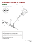
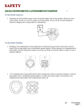
Learning Guide CHASSIS SPECIALIST ELECTRIC POWER STEERING COURSE NUMBER: W013-01 Chassis Specialist : Electric Power Steering Notice Due to the wide range of vehicles makes and models, the information given during the class will be general in nature and should not be taken as specific to any vehicle/unit. Please consult manufacturer specifications for the correct number/specifications and repair procedures for the vehicle you are testing. This document is meant to be used as a guideline only. For further information, please contact toll-free: 1-855-813-2101 or email [email protected] No part of this book may be reproduced, stored in any retrieval system or transmitted in any form or by any means (including but not limited to electronic, mechanical, photocopying and recording) without prior written permission of CARS Training Network Inc. This applies to all text, illustrations, tables and charts. Copyright © 2014 CARS Training Network Inc Page ii Chassis Specialist : Electric Power Steering Table of Contents Table of Contents ................................................................................................................................... iii Introduction ............................................................................................................................................. 1 Objectives ............................................................................................................................................................................. 1 Rationale ............................................................................................................................................................................... 1 Description ............................................................................................................................................................................ 1 Electric Power Steering Systems ........................................................................................................... 2 Electric Power steering System components ........................................................................................................................ 4 Steering Rack and Pinion Assembly .................................................................................................................................................... 4 EPS Motor ........................................................................................................................................................................................... 5 EPS Sensors ......................................................................................................................................................................................... 5 Power Steering Control Module (PSCM) ............................................................................................................................................ 7 Operation and Diagnosis ........................................................................................................................ 8 Ford Electric Power Steering Assist System (EPAS) ........................................................................................................... 8 EPAS Column Assembly Initialization .............................................................................................................................................. 10 General Motors Electric Power Steering (EPS) .................................................................................................................. 10 Delphi System Initialization............................................................................................................................................................... 17 Steering Position Sensor Calibration.................................................................................................................................................. 17 Torque Sensor Calibration ................................................................................................................................................................. 18 Steering Tuning Selection .................................................................................................................................................................. 18 Koyo System Initialization................................................................................................................................................................. 19 Torque Sensor Calibration ................................................................................................................................................................. 19 Steering Angle (Position) Sensor Centreing ...................................................................................................................................... 20 Saturn Astra Electro-Hydraulic Power Steering................................................................................................................................. 21 Honda Electric Power Steering (EPS) System .................................................................................................................... 22 EPS Indicator Light Operation ........................................................................................................................................................... 23 Toyota Electric Power steering (EPS) system ..................................................................................................................... 27 Glossary.................................................................................................................................................. 31 Page iii Chassis Specialist : Electric Power Steering Introduction OBJECTIVES Upon successful completion of this lesson, participants will be able to: Describe the operation and control methods used on OEM electric power steering systems Perform diagnosis and repair of the electric power steering systems Perform system setup after repairs and alignments RATIONALE Due to fuel economy and noise concerns vehicle manufacturers have developed electric power steering systems. As these systems become more prevalent in vehicles, technicians and service personnel will have to become familiar with the diagnosis and operation of these systems. DESCRIPTION This course will cover operation, diagnosis and repair aspects related to vehicles equipped with electric power steering systems. This course will highlight the different systems used by vehicle manufacturers. System defaults and diagnostic aids will be covered. Page 1 Chassis Specialist : Electric Power Steering Electric Power Steering Systems Power steering systems were originally developed in the early 1950’s; the first production vehicle being the 1951 Chrysler Imperial. These systems were hydraulic with a pump being driven by the vehicle’s engine. As it is difficult to turn the steering wheel at low speeds, automobile manufacturers were forced to install very large steering wheels. The large steering wheel was required to provide a driver enough mechanical advantage at low speeds when the tire to pavement friction is at the highest. The introduction of power steering allowed for smaller steering wheels and redesigned interior space. The hydraulic systems used in the 1950’s are very similar to the systems still in use today. Granted, development has progressed on the power steering pumps and hydraulic valves. Power steering systems still require engine horsepower to operate. As fuel economy standards tightened and power train packaging decreased in size, engineers were forced to develop new power steering systems. This course will look at the electric power steering (EPS) systems used by Ford, General Motors, Honda and Toyota. The first electric power steering system on a production vehicle debuted in 1993 in the Acura NSX. Currently, there are four different electric power steering system configurations. The Acura NSX uses a rack assembly with a motor mounted internally. The double pinion style EPS system uses an electric motor mounted externally to the pinion. The third configuration is having the electric motor mounted internally in the pinion. The forth and final EPS system has the electric motor mounted on the steering column. This is the most common system found on today’s vehicles. These systems are currently manufactured by Koyo Seiko, Delphi, NSK, ZF and TRW Automotive. The first system offered on a production vehicle was on the Acura NSX. This system is very complex using an electric motor and a recirculating ball and screw assembly all mounted inside the steering rack. The DC motor armature rotates around the steering rack and drives a helical gear that is meshed to the ball screw assembly. The ball screw assembly is clamped to the rack which will transfer the steering motion directly to the rack. The steering wheel torque sensor is mounted in the pinion housing and a steering wheel speed sensor is mounted in the steering column. Based on the data from the torque sensor and speed sensor along with the vehicle speed input from the engine control module (ECM) the Page 2 Chassis Specialist : Electric Power Steering EPS controller will determine the appropriate assist level. This system is compact but very expensive; any failure of the motor, sensor or internal mechanical devices makes the steering gear replacement necessary. The double pinion EPS system has the motor assembly located in a separate housing. The pinion motor drives a second pinion gear to assist the pinion attached at the column. The system is not as complex as the Acura one but is larger and requires more space under the hood. The EPS motor can be serviced separately. The Honda Insight, Civic Si and Hybrid along with the Toyota Prius use an EPS system which has the electric assist motor mounted to the steering gear’s pinion assembly. The electric motor is directly linked to the pinion gear and is serviceable. This system is compact and cost effective. It will take up slightly more room than a conventional rack and pinion steering gear. The column mounted EPS system has the motor assembly mounted to the column. The motor will assist the driver’s steering input through a worm shaft and reduction gear. This system uses a very compact rack and pinion assembly, the motor occupying the open space under the instrument panel cluster. Page 3 Chassis Specialist : Electric Power Steering One of the benefits of EPS is an increase in fuel economy, according to Ford this increase can be up to one mile per gallon. On a conventional power steering system, the pump will always be operating whenever the engine is running. With the EPS system there is no parasitic draw on the engine. The electrical power the system uses is readily available and draws on the system only when required. Other benefits of the EPS systems are there are no hydraulic lines and less fluid, also, the rack and pinion is smaller and lighter. ELECTRIC POWER STEERING SYSTEM COMPONENTS While the systems might be configured differently the operation and principles are the same. The EPS is designed to reduce the effort needed to steer the vehicle. The systems consist of the steering rack and pinion, a steering wheel position and/or steering torque sensor(s), a power steering control module (PSCM) and the electric motor. The PSCM will monitor the vehicle speed signal via the controller area network (CAN) to adjust the assist level provided. Steering Rack and Pinion Assembly The rack and pinion assembly on an EPS equipped vehicle is smaller and lighter. The rack and pinion does not have an internal spool valve to control the hydraulic assist. The assembly does contain oil but the oil is used for lubrication only, there is no hydraulic pressure in the system. Page 4 Chassis Specialist : Electric Power Steering EPS Motor The EPS motor can either be a brushless or brushed reversible motor. Depending upon the motor’s location it will provide assist at the steering gear or the steering column. The motors used in nonHybrid vehicles are 12 volts DC and will be rated between 35 and 80 amps. On some applications the motor will also be a part of the power steering control module (PSCM). The motor will either drive a worm gear in the steering column internally through a recirculating ball screw assembly or through the steering gear pinion. The motors used on Hybrid vehicles will vary from a 12 volt system up to a 50 volt system depending upon the application. EPS Sensors Depending upon the manufacturer, the EPS system will have one or two sensors. The systems that use a single sensor will have a steering wheel torque sensor. The sensor measures the torsional twist that occurs when the steering wheel is turned. The power steering control module uses this sensor to determine the amount of assist required based on vehicle speed and tire size. The sensor typically consists of a compensation coil, a detecting coil and three detecting rings. To measure the torque in the steering column the detecting rings have toothed edges that face each other. Detecting ring #1 is mounted to the steering column output shaft while detecting rings #2 and #3 are both mounted to the input shaft. The detecting coil is mounted around the toothed edges of detecting rings 1 and 2. As the steering wheel is turned the alignment of the toothed edges changes due to the torque on the shaft. This changes the signal voltage of the detecting coil. The power steering control module PSCM interprets the change in voltage as torque being applied to the shaft. Page 5 Chassis Specialist : Electric Power Steering The compensating coil is used to buffer changes in the electrical current caused by temperature, varying electrical loads and system voltage providing the detecting coil with a constant voltage with which to accurately detect steering wheel movement. The detecting sensor is a dual analogue sensor that uses a 5 volt reference and is valid between 0.25 and 4.75 volts. The sensor operates by having one signal voltage reading high and the other signal voltage showing low. This gives a mirror effect, when sensor 1 voltage is high then sensor 2 voltage will be low. TORQUE SENSOR SIGNAL 1 TORQUE SENSOR SIGNAL 2 Snap shot of a 2004 Malibu Torque Sensor on a right turn The steering wheel position sensor is used by the PSCM to determine when the steering wheel is in the centre position. As the EPS system will try to give the driver the same “over centre feeling” and provide the “return to centre” that a hydraulic system does, the PSCM has to know the centre position. The sensor is an analogue triangle dual signal device that uses a 5 volt reference. The sensor readings are valid between 0 and 5 volts but the sensor’s dual signals (Signal 1 and Signal 2) must be within 2.5 to 2.8 volts of each other when the steering wheel is turned. If the voltages are out of range the PSCM will disable the power steering assist and set a DTC. Page 6 Chassis Specialist : Electric Power Steering STEERING POSITION SENSOR SIGNAL 1 STEERING WHEEL POSITION SENSOR SIGNAL 2 Steering Wheel Position Sensor Signals Power Steering Control Module (PSCM) The power steering control module (PSCM) is the brain of the system. By using inputs from the torque sensor and/or position sensor, battery voltage, engine speed as well as a vehicle speed signal from the engine control module (ECM) or body control module (BCM), the PSCM is able to provide the correct level of assist by commanding the EPS motor. The PSCM will be able to tailor the assist based on steering input and vehicle speed. The assist is greater at lower speeds and is reduced as the vehicle speed increases. The PSCM also provides thermal protection for the EPS motor. The PSCM will reduce the current to the EPS motor to prevent damage from excessive current such as when the steering wheel is held on the steering stops during a parking manoeuvre. The PSCM will also illuminate a service steering system light or message whenever a system fault has been detected. The PSCM is wired to the vehicle’s Controller area network (CAN). Page 7 Chassis Specialist : Electric Power Steering Operation and Diagnosis In this section the various EPS systems will be discussed. This section will be broken down by vehicle manufacturer—Ford, General Motors, Honda and Toyota. FORD ELECTRIC POWER STEERING ASSIST SYSTEM (EPAS) Ford refers to the electric power steering system as Electronic Power Assist Steering or EPAS. The system consists of a steering column which contains the power steering control module (PSCM), the electric motor, the torque sensor and a steering gear coupled with an intermediate shaft. This system does not use a steering wheel position sensor unless the vehicle is equipped with the Electronic Stability Programme (ESP). The PSCM determines the necessary assist based on input from the torque sensor as well as the suspension and tire information programmed into the module. The steering wheel torque sensor uses dual analogue sensors to inform the PSCM which direction the steering wheel is being turned. If the steering wheel is turned to the left, the left signal increases while the right signal decreases. The opposite occurs when the steering wheel is turned to the right, the right signal increases and the left signal decreases. The system will operate when the vehicle’s system voltage is between 10 and 16 volts. Power to the EPS system is provided via an 80 amp fuse, used to power the EPS motor, and a 10 amp fuse, used to power the PSCM. The PSCM uses the vehicle high speed CAN bus for vehicle speed information. Diagnostic trouble codes can be accessed using a scan tool. When a trouble code is set the PSCM will request the instrument panel (IPC) to illuminate the service steering soon light or message. The following are the trouble codes the system will set DTC Description B1317 Battery Voltage High B1318 Battery Voltage Low B1342 Internal ECU Fault B2277 Electric Power Steering Motor Malfunction B2278 Steering Shaft Torque Sensor Malfunction Page 8 Chassis Specialist : Electric Power Steering B2477 Module Configuration Failure B3104 Steering Shaft Position sensor Malfunction C2000 Steering Angle Sensor Not Calibrated U0100 Loss of Communications with the ECM/PCM U0101 Loss of Communications with the TCM U0155 Loss of Communications with the Instrument Panel Cluster (IPC) U2023 Fault Received from External Node C1277 Steering Wheel Angle 1 and 2 Circuit Failure C1278 Steering Wheel Angle 1 and 2 Signal Failure For trouble codes B1317 and B1318, check the system voltage is between 10 and 16 volts at the PSCM connector. For DTC’s B2277, B2278 B3104, C1277 and C1278 inspect for an open or short in the PSCM power feed or an open or short in the high speed CAN bus. If ok, suspect an internal failure of the torque or position sensors or an internal short or open in the EPAS motor. If the customer concern is steering related with no diagnostic trouble codes, it will be necessary to inspect mechanical components. Verify the tires and the pressures are correct. Inspect the steering column for binding, loose steering column bolts and inspect the intermediate shaft for binding. Inspect the steering gear, tie rod ends and other suspension components. If the PSCM requires replacement the new module will require programming. The PSCM needs to be programmed “vehicle specific”. The suspension option, tire size and power train options are used by the PSCM to determine the correct assist level for the vehicle. If there is a problem with the EPAS motor, the torque and/or position sensors or there is a problem with the steering column it will have to be replaced as an assembly. After replacing the steering column it also has to be initialized. Page 9 Chassis Specialist : Electric Power Steering EPAS Column Assembly Initialization 1. Have the vehicle on a flat level surface with the transmission in PARK 2. Place the steering wheel in the straight ahead position 3. Connect the scan tool to the diagnostic link connector (DLC) 4. Turn the ignition to RUN 5. Select ESP sensor calibration on the scan tool menu and follow the on screen instructions 6. Clear all power steering system trouble codes from all modules 7. Turn the ignition to the OFF position and wait at least 25 seconds before performing any other repairs that may require the battery to be disconnected or the EPAS module be disconnected. 8. Road test the vehicle to verify repairs GENERAL MOTORS ELECTRIC POWER STEERING (EPS) General Motors uses three different EPS systems. One is manufactured by Delphi and is used on the Chevrolet Malibu, and the Pontiac G6. The second system is manufactured by Koyo and is used on the Chevrolet Cobalt, HHR and Equinox, the Pontiac Torrent and G5 (Pursuit) and the Saturn Ion and the Vue. The third system is used on the 2009 Saturn Astra and is an electro-hydraulic system. In 2004 General Motors Malibu Steering Column Assembly introduced the Delphi EPS system on the Chevrolet Malibu. This system consists of a 65 amp brushless DC electric motor with an integral PSCM mounted to the steering column. The system uses both a torque sensor and a steering wheel position sensor to monitor the steering input. Page 10 Chassis Specialist : Electric Power Steering The torque sensor is the main input that the PSCM uses to determine the steering direction and the amount of assist to provide. The steering column input and output shafts are separated by a torsion bar that has the sensor mounted to it. The sensor is a dual signal sensor similar to the model that Ford uses. The sensor is a 5 volt sensor that operates between 0.25 and 4.75 volts. When the steering wheel is turned to the right the sensor 1 voltage will increase while the sensor 2 voltage decreases. The opposite occurs on a left hand turn. The steering wheel position sensor is used by the PSCM to determine when the steering wheel is in the centre position. The PSCM uses the position sensor to help return the steering wheel to the centre position. The sensor is a 5 volt analogue triangle sensor that will operate between 0 and 5 volts and the sensor voltages will stay within 2.5 to 2.8 volts of each other. FUSE FUSE CAN Communications MALIBU EPS WIRING SCHEMATIC Page 11 Chassis Specialist : Electric Power Steering The EPS motor and PSCM are serviced as an assembly separate from the steering column. The PSCM assembly is calibrated specific to the vehicle. The calibration is referred to as the Steering Tuning Selection. System voltage is critical to the operation and is constantly monitored. The EPS motor is rated at 65 amps. Due to the large current required to operate the EPS motor, the PSCM has a built in thermal protection feature. The internal software continuously monitors the current usage and compares the value with known heat build up information. If the heat threshold is exceeded, the PSCM will limit current to the EPS motor by pulse width modulation (PWM). In this case the operator will notice a reduction in power assist. The scan tool data display can be used to diagnose intermittent conditions. The chart below shows the typical values the system should display with the ignition on, engine running, steering wheel centred and no force applied to the steering wheel. Parameter Units Typical Value Battery Voltage Volts 14.2 Calculated System Temperature Degrees C/F Varies Motor Command Amps 0 Steering Shaft Torque N.m /ft-lbs 0.00 Steering Position Sensor Signal 1 Volts Varies Steering Position Sensor Signal 2 Volts Varies Steering Tuning Numeric 1, 2, 3, 4, 5, 6, 7 or 8 Steering Wheel Position Degrees 0 Torque Sensor 1 Volts 2.5 Torque Sensor 2 Volts 2.5 Vehicle Speed kmh/mph 0 Page 12 Chassis Specialist : Electric Power Steering The Koyo system used by the Cobalt, G5, Equinox, Torrent, Ion and Vue is basically the same as the Delphi system with the exception of the steering wheel position sensor, the PSCM is separate from the motor and the motor itself is not serviceable. The EPS motor is rated at 58 amps. Cobalt Steering System The Koyo PSCM contains 8 steering calibrations which are based on the vehicle’s options. The steering calibrations are based on information stored in the body control module (BCM). Vehicle speed information to the PSCM is sent via the high speed GM LAN. The PSCM sends a warning message to the IPC via the GM LAN to indicate a system fault. As with the Delphi system, the Koyo system protects the EPS motor from thermal damage through software algorithms. Current to the EPS motor will be reduced by PWM during an overheating situation. As the system does not have a steering wheel position sensor there will not be any return to centre assist. Page 13 Chassis Specialist : Electric Power Steering RUN/START FUSE BLOCKUNDERHOOD POWER DISTRIBUTION SCHEMATICS IN WIRING SYSTEMS EPS FUSE 60A EPS STR WHL CNTRL Fuse 19 POWER DISTRIBUTION 2A 60A SCHEMATICS IN BODY CONTROL MODULE (BCM) WIRING SYSTEMS DLC Schematics in Computer/Integrating Systems POWER DISTRIBUTION SCHEMATICS IN WIRING SYSTEMS Battery Positive Voltage Ignition 1 Voltage LEFT ASSIST MOTOR CONTROL High High Speed Speed GMLAN GMLAN Serial Data Serial Data Bus+ Bus- High High Speed Speed GMLAN GMLAN Serial Data Serial Data Bus+ Bus LOGIC RIGHT ASSIST MOTOR CONTROL STEERING COLUMN ASSEMBLY POWER STEERING CONTROL MODULE (PCSM) GROUND ELECTRIC POWER STEERING (EPS) MOTOR STEERING SHAFT TORQUE SENSOR COBALT EPS WIRING SCHEMATIC The Saturn Astra uses an electro hydraulic system. The system consists of a PSCM, steering column with an integral torque sensor, EPS motor and steering gear. The system is different than the other two systems as the EPS motor is used to increase hydraulic pressure to assist the steering system. The PSCM will PWM the current to the EPS motor based on vehicle speed, torque sensor input and vehicle suspension options. If the vehicle is equipped with a stability system then a steering wheel position sensor will be added to the column. The Astra uses two different EPS systems; one is built by TRW and communicates on a dedicated diagnostic line (pin 7 on the DLC). The other system is built by ZF and communicates on the high speed GM LAN. The TRW system can be identified by a round fluid reservoir, the EPS wiring harness cannot be disconnected at the motor and the hydraulic lines are individually connected to the motor unit. Diagnostic trouble codes can be accessed using a scan tool. The list below is a typical list of EPS trouble codes. Page 14 Chassis Specialist : Electric Power Steering Trouble Codes Description C0000 Vehicle Speed Information Circuit C0176 System Thermal Error C0460 Steering Position Sensor C0475 Electric Steering Motor Circuit C0545 Steering Wheel Torque Input Sensor C0550 Electronic Control Unit (ECU) Performance C0896 Device Voltage/Range Performance C0897 Device Power Mode-ing Error C0899 Device Voltage Low C0900 Device Voltage High C0845 Device Ignition 1 Circuit (Cobalt and G5) C0895 Device Voltage (Equinox, Torrent and Vue) C0561 System Disabled information Stored (Equinox) C056D ECU Hardware Performance C056E ECU Software Performance C0800 Device Voltage Page 15 Chassis Specialist : Electric Power Steering C1508 Internal Motor Circuit Malfunction (Saturn Astra) C1512 Temperature Sensor Circuit (Saturn Astra) C1517 Overheat Protection Mode Malfunction (Saturn Astra) C1523 System Voltage (Saturn Astra) C1525 Engine Running Signal (Saturn Astra) C1527 Motor Circuit (Saturn Astra) C1528 Motor speed Invalid Signal Malfunction (Saturn Astra) C1529 Motor Circuit (Saturn Astra) C1550 ECU failure (Saturn Astra) On the Delphi system, if there is a fault with the torque or position sensors, the steering column will have to be replaced. The motor/PSCM can be serviced separately. If the vehicle comes in with a steering complaint refer to the chart below Complaint Inspect Rattle, Clunk or Noise Worn suspension Components from the Steering System Steering gear Intermediate Shaft Steering Column Increased Steering Effort Correct Tire Size, Wear and Inflation Intermediate Shaft Steering Gear Page 16 Chassis Specialist : Electric Power Steering Inspect the Lower Control Arms Poor Steering Return Inspect the Steering Knuckles and Strut Bearings Inspect the Ball Joints and Axles Steering Wheel when Turning jerks Inspect for Worn Suspension Components Binding in the Intermediate Shaft, Steering Gear or Column Inspect the EPS motor for excessive Heat Steering Wheel Kickback Inspect for Loose Column and rack bolts Inspect for Damaged Tie Rod Ends Delphi System Initialization The EPS system requires a setup procedure when ever the PSCM or steering column is replaced. If the PSCM is replaced, the steering position sensor, torque sensor and steering tuning selection will have to be setup. If the column is replaced then only the position and torque sensor require initialization. After performing an alignment, the torque sensor and position sensor will require calibration. If the sensors are not calibrated, the customer may complain of poor return to centre feel or the steering wheel moving back and forth by itself. To perform the system setup a scan tool is required. Steering Position Sensor Calibration 1. On a flat level surface install the scan tool 2. Turn ON the ignition with the engine OFF 3. Centre the steering wheel 4. Build the vehicle and select the special functions menu in the steering system menu 5. Highlight the Steering Position Sensor Calibration and press enter. The screen will flash “Calibration in Progress” and when finished will show “Calibration Complete” 6. Exit from the calibration screen 7. Clear all steering system DTC’s from all modules. 8. Turn the ignition OFF After turning off the ignition DO NOT disconnect the battery or EPS module for 25 seconds before proceeding with other vehicle repairs or the module will not retain the information that was inputted. Page 17 Chassis Specialist : Electric Power Steering Torque Sensor Calibration 1. On a flat level surface install the scan tool 2. Turn the ignition ON with the engine OFF 3. Centre the steering wheel. After centreing the steering wheel do not touch the steering wheel and verify there is no force being applied to the steering wheel or system. 4. Build the vehicle and select the special functions menu in the steering system menu 5. Highlight the Steering Torque Sensor Calibration and press enter. The screen will flash “Calibration in Progress” and when finished will show “Calibration Complete” 6. Exit from the calibration screen 7. Clear all steering system DTC’s from all modules. 8. Turn the ignition OFF After turning off the ignition DO NOT disconnect the battery or EPS module for 25 seconds before proceeding with other vehicle repairs or the module will not retain the information that was inputted. Steering Tuning Selection 1. Install the scan tool 2. Turn ON the ignition with the engine OFF 3. Build the vehicle and select special functions from the steering system menu 4. Highlight and select the Steering Tuning Selection and press the enter key. The scan tool screen will begin to flash “Selection in Progress”. When completed the screen will display “Selection Complete”. 5. Clear all EPS trouble codes from all modules 6. Turn the ignition OFF After turning off the ignition DO NOT disconnect the battery or EPS module for 25 seconds before proceeding with other vehicle repairs or the module will not retain the information that was inputted. Page 18 Chassis Specialist : Electric Power Steering Koyo System Initialization On the Koyo system, the PSCM is serviced separately, all other components are serviced as an assembly. If the vehicle comes in with a steering complaint refer to the Delphi chart above for information with the following exception: To test the Koyo system for a clunk, rattle noise or vibration at low speeds, remove the 60 amp EPS fuse—usually located in the under hood junction block. Drive the vehicle in the same manner to try and duplicate the concern. If the noise is still evident, the cause of the customer’s concern is in the steering column. By removing the EPS fuse the motor has no power so the noise heard can only be from the steering column or intermediate shaft. If the concern is only detected every 90 degree of steering rotation, then the intermediate shaft is binding. Whenever the PSCM or steering column is replaced the torque sensor and/or the steering position must be calibrated. While it is not necessary to calibrate the sensors after an alignment, a customer may complain about poor “on centre feel”. Torque Sensor Calibration As there is no steering assist when performing this procedure it is recommended to slightly raise the vehicle off the ground. 1. Install a scan tool 2. Turn ON the ignition with the engine OFF 3. Build the vehicle and from the steering system select the special function menu 4. Highlight and select the Steering Position/Torque Sensor Calibration and press the enter button 5. Centre the steering wheel 6. Now turn OFF the ignition and remove the ignition key from the cylinder 7. Wait 29 seconds before inserting the key and turning the ignition ON with the engine OFF 8. Turn the steering wheel 180 degrees to the left of centre and hold it there briefly 9. Now turn the steering wheel 180 degrees to the right of centre and hold the steering wheel briefly 10. Return the steering wheel to the centre position. Verify the steering wheel is centred and there is no force being applied to the vehicle’s suspension and steering system Page 19 Chassis Specialist : Electric Power Steering 11. Observe the scan tool and wait until the display reads “Calibration Complete”. Enter the steering system data list and verify the steering wheel position (if equipped) reads 0 +/- 5 degrees. If the steering wheel position sensor reads outside of the parameter, the display should read “Procedure Failed”, try to repeat the calibration again. 12. Exit from the steering system menu and check the steering for any uneven feel while rotating the steering wheel from side to side. 13. Clear all EPS trouble codes from all modules. 14. Turn the ignition OFF After turning off the ignition DO NOT disconnect the battery or EPS module for 25 seconds before proceeding with other vehicle repairs or the module will not retain the information that was inputted. If the vehicle has a steering wheel position (or angle sensor), the centre position will also have to be calibrated in the electronic brake control module (EBCM) Steering Angle (Position) Sensor Centreing The steering wheel position sensor must be centred whenever the steering gear, column, position sensor, intermediate shaft or EBCM has been replaced. The steering position sensor requires a scan tool to calibrate it. 1. Park the vehicle on a flat level surface, transmission in PARK 2. Install the scan tool and build the vehicle 3. Turn the ignition ON with the engine OFF 4. From the vehicle control systems/module set up menu access the EBCM/Steering position Sensor Calibration 5. Follow the scan tool directions to complete the procedure. You will have to turn the steering wheel left 5 degrees and right 5 degrees and back to the straight ahead position 6. Clear all EPS diagnostic trouble code in all module 7. Procedure has been completed Page 20 Chassis Specialist : Electric Power Steering One common customer complaint on both systems is a no steering assist concern. This usually happens in a parking lot manoeuvre or when a vehicle is being used for driver instruction. If the steering wheel is held on the steering stop, the PSCM will command maximum current to the motor. If the steering wheel is held in this position for several seconds, the PSCM will limit the current to the EPS to protect against excessive heat. The driver will be able to detect the loss of assist and usually the driver information centre will display No Steering Assist and the service steering system light will illuminate. The PSCM will set a DTC C0176, system thermal error or a C0476, electric power steering motor circuit range/performance. If a vehicle has either of these trouble codes set in history, ask the customer about the operating conditions when the fault occurred. If the steering system is relaxed for a couple of minutes the power assist will return after the PSCM has determined the EPS motor has cooled sufficiently. Saturn Astra Electro-Hydraulic Power Steering Beginning with the 2008 model year Saturn introduced the Astra. This compact vehicle uses an electric hydraulic power steering (EHPS) system. The Astra uses one of two different versions of the EHPS system depending on the options it is built with. One is manufactured by TRW and is used on vehicles with the base engine and suspension. The other system is built by ZF and is used on vehicles with the larger engine and up-level suspension system. The system consists of a steering column with an integrated torque sensor, a PSCM and an electric hydraulic power steering pump. The steering column and torque sensor are serviced as an assembly while the PSCM, hydraulic motor and steering gear are serviced individually. On models with either the ZF or stability control they will also have a column integration module (CIM) which incorporates a steering angle sensor. The steering column motor and torque and/or position sensors operate the same as on the other GM vehicles. This system differs by using hydraulic pressure supplied by an electric pump. The PSCM uses information from the CAN network regarding vehicle speed and from the torque sensor to determine the correct steering assist. The PSCM then communicates this calculation to the control unit of the hydraulic pump. The control unit controls the pump speed and hydraulic pressure. The pump and control unit are serviced as an assembly. Due to the power required to run the motor and pump, the engine must be running for the system to operate. The TRW and ZF components cannot be interchanged. As the system uses pressurized hydraulic fluid, the level must be checked at regular service intervals. To check the fluid level, remove the cap located on the right side of the engine compartment. It is located between the engine and the front bulkhead. Verify the level reads correctly on the dipstick. If Page 21 Chassis Specialist : Electric Power Steering the fluid is low top up with the special Saturn power steering fluid for this vehicle. Do not overfill the system. A scan tool must be used to access system diagnostic trouble codes and perform the steering control module setup. HONDA ELECTRIC POWER STEERING (EPS) SYSTEM Honda uses a rack drive electric motor for the EPS system used on the Civic Si. The system consists of an EPS control module, EPS motor, torque sensor and a centre take off steering gear. The EPS control unit receives data from the torque sensor, the vehicle speed sensor and the ECM for engine speed. Based on the information provided by the inputs, the EPS controller will inform the ECM of the power steering operation via the power steering switch and command the EPS motor to operate. The EPS controller also monitors the power steering system for faults. The EPS controller performs two different self diagnostic modes. One is done when the engine is initially started and ends after the bulb check. The second mode continues after the first is completed and will continue until the ignition switch is turned off. If a system fault is detected, the EPS controller will command the EPS indicator in the instrument panel on, store the trouble code and will disable the electric assist. Manual steering will still be available. If the EPS controller cannot store the trouble code, the EPS indicator in the instrument panel will begin to flash. Once a diagnostic code has been set the EPS controller will store the code—but can only store the single code once. If the code is continuously resetting, the information stored by the EPS controller will be from the last failure. The EPS controller is located behind the right side kick panel The torque sensor on the Honda EPS system is mounted on the steering gear pinion. The sensor is a dual signal analogue 6 wire sensor that transfers the mechanical rotation of the steering shaft to an electrical signal the EPS controller can use. The sensor connector has seven cavities but only six are used. Cavity Purpose 1 Sensor Output (VT6) 2 Reference Voltage 5 Volts 3 Sensor Output (VT3) 4 Sensor Ground 5 Not Used 6 Reference Voltage 12 Volts 7 Torque Signal Output (5 volts momentarily on start up) Page 22 Chassis Specialist : Electric Power Steering EPS Indicator Light Operation Whenever the EPS indicator is illuminated, the vehicle will have reduced or no power steering assist. The light will illuminate briefly for a bulb check on start up and will illuminate anytime a system fault is detected. The light will illuminate if the EPS controller is defective or loses battery power but no diagnostic codes will be set. If a torque sensor code is set, the light will remain on until the DTC is cleared. Engine speed, vehicle speed and voltage concerns will set a DTC and keep the light on until the system detects normal operation. No other system DTC’s keep the indicator on until the end of the key cycle. The indicator light can be commanded on due to three customer induced driving habits. The first condition is if the vehicle is driving at or above 20 km/h (12.4 mph) with a sudden rapid change in speed, the speed signal drops or the vehicle stops for 5 seconds and the engine speed remains above 1,649 rpm. The second condition is if the vehicle or speed signal reads 0 km/h for 10 seconds with an engine speed of 1,640 rpm or higher for 20 seconds. The last condition the customer can set is the engine speed is less than 280 rpm with the vehicle travelling above 10km/h (6.2 mph) for greater than 3 seconds. Diagnostic trouble codes can be read using a scan tool. Turn the ignition OFF before connecting the scan tool. The DLC is located under the dash on the driver’s side. Turn the ignition ON and follow the prompts on the scan tool. If a scan tool is not available, system codes can be retrieved by using the Service Check Signal Method Verify the wheels are in the straight ahead position with the ignition OFF Short DLC pin 9 to ground Turn the ignition ON with the engine OFF Observe the EPS indicator light blinking in the instrument panel The indicator will display long and short blinks. The long blinks indicate 10’s with the short blinks indicate single numbers (i.e. four long blinks followed by two short blinks indicates a code 42.) After retrieving the trouble codes turn the ignition off and remove the jumper cable from pin 9 of the DLC Long blinks (two times) Short blinks (three times) ON OFF Example of DTC 23 Page 23 Chassis Specialist : Electric Power Steering Flash Code Possible Component 11 High or Low Ignition Voltage 12 High or Low System Voltage 21 Vehicle Speed Signal 22 Engine Speed Signal 31 Torque Sensor Neutral Position 32 Internal ECU Failure 33 Internal EPS Motor Fault 34 Power or Fail Safe Relay Stuck On 35 EPS Control Unit Internal Circuit Malfunction 36 EPS Control Unit Output Circuit Fault 37 EPS Control Unit Step Up Circuit Fault 51 Torque Sensor Fault 61 Open or Short in the EPS Motor wiring Harness 71 Motor Angle Sensor Fault Page 24 Chassis Specialist : Electric Power Steering Trouble codes can be cleared by using the Service Check Signal Circuit Method. The steps must be followed exactly in order to clear the codes. With the ignition switch OFF ground pin 9 of the DLC The vehicle must be on the ground with the steering wheel in the straight ahead position Turn the ignition switch to the ON position. The EPS indicator should be illuminated for 6 seconds. Within 4 seconds of turning the switch on, turn the steering wheel left 45 degrees from the straight ahead position and hold the steering wheel in that position until the EPS indicator turns OFF Within 4 seconds of the EPS light turning OFF return the steering wheel to the straight ahead position and release the steering wheel. The EPS light should illuminate within 4 seconds of releasing the steering wheel Within 4 seconds of the light coming back on turn the steering wheel back 45 degrees to the left and hold it in that position. The EPS light should go out after 4 seconds. Within 4 seconds of the light turning OFF return the steering wheel to the centre position and release the wheel. The EPS light should blink twice within the next 4 seconds to indicate the DTC’s have been cleared. After the EPS light has blinked twice turn the ignition switch to the OFF position Remove the jumper wire and verify all codes have been cleared. Page 25 Chassis Specialist : Electric Power Steering The EPS system can be checked for the correct Level of Assist. Verify the vehicle has the original equipment tires and wheels and that the tire inflation is correct Start the engine and let the engine idle Attach a spring scale (commercially available) to the steering wheel. With the engine idling on a clean and level floor pull on the scale and read the measurement as soon as the tires begin to move The scale reading should be no more than 29 Newton’s or 6.6 ft. lbs. If the reading is higher inspect the tire pressure, steering linkage, steering rack and finally the EPS system The Steering Wheel Rotational Play Check can also be checked ROTATIONAL PLAY: 0-10MM (0-3.9in.) Put the steering wheel and tires in the straight ahead position Measure how far the steering wheel can be turned left and right without the front wheels turning The play should be within 0 to 10 mm (0-0.39") If the steering is within the limits, the system is ok. If there is excessive play inspect the steering gear guide adjustment, the steering linkage and the steering gear The Honda EPS system has a built in thermal overload protection programme. The EPS controller will reduce current to the EPS motor when excessive heat is detected, such as repeated turns to the steering stops. The level of power steering assist will be reduced as necessary. The EPS indictor does not illuminate and no DTC’s are stored. The system will restore full assist if the system detects no steering torque sensor input or the ignition is cycled to the OFF position. It may take up to 15 minutes for the EPS motor to cool down enough for full assist to be returned. Page 26 Chassis Specialist : Electric Power Steering TOYOTA ELECTRIC POWER STEERING (EPS) SYSTEM Toyota also uses a steering column with an electric assisting motor. Torque is generated through the motor and a reducing gear installed in the steering column shaft. The EPS ECU monitors the vehicle speed, the skid control ECU and torque sensor to determine the correct amount of assist to apply. The assist level is adjusted so there is more assist at lower speeds and virtually no assist at high speed. The torque sensor is part of the steering column assembly and converts the mechanical force applied to the steering wheel to an electrical signal the EPS ECU can use. The sensor is the same design as the Honda, Ford and GM units. The EPS motor assembly is also similar to the other vehicles. Current is provided by the EPS ECU based on the input signals from the torque sensor, vehicle speed and skid control information. The motor contains a rotation angle sensor to fine tune the electric steering control. The sensor is a resolver sensor which detects the rotation angle of the motor and relays the information back to the EPS ECU. System diagnostic trouble codes can be read and cleared with a scan tool or through the DLC. To access the trouble codes without the Toyota Intelligent Tester perform the following steps Using the correct terminals jump pins 4 and 13 of the DLC together, verify the ignition is OFF Turn the ignition switch ON with the engine OFF The trouble codes will be flashed by the EPS indicator located in the instrument panel Codes will be displayed after four seconds. The light will flash ON for 0.5 seconds followed by another 0.5 seconds with the light OFF. This indicates the 10’s numbers. The 10’s numbers will be followed by a 1.5 second pause before the single digit numbers. If there is a second or third code the next code will be followed by a 2.5 second pause. All trouble codes are displayed in ascending order. Refer to the illustration below. Page 27 Chassis Specialist : Electric Power Steering CODE 21 (ON for half second) ON Combination Meter OFF SECONDS NORMAL CODE ON Power Steering Warning Light OFF SECONDS Page 28 Chassis Specialist : Electric Power Steering DTC/ DTC Description Possible Component C1511/11 Torque Sensor Circuit 1 Torque Sensor or ECU C1512/11 Torque Sensor Circuit 2 Torque Sensor or ECU C1513/11 Excessive Torque Sensor Deviation Torque Sensor or ECU C1514/11 Torque Sensor Supply Voltage Torque Sensor or ECU C1521/25 Short in the EPS Motor Circuit ECU C1524/24 Motor Terminal Voltage Malfunction Torque Sensor or ECU C1528/12 Motor Rotation Angle Sensor Torque Sensor or ECU C1531/25 ECU Malfunction ECU C1532/25 ECU Malfunction ECU C1533/25 Temperature Sensor Circuit ECU C1534/25 EEPROM Error ECU C1551/25 Power Supply Malfunction ECU, ECU fuse, Ignition Supply Ckt. C1552/22 Power Supply Voltage Malfunction ECU or Power Supply Circuit C1554/23 Power Supply Relay Malfunction ECU or Power Source Circuit C1555/25 Motor Relay Welding Failure ECU C1581/26 Assist Map Number Unwriting ECU U0073/49 Module Off the Communication Bus CAN Communication System U0105/41 Loss of Communication with Injector Module CAN Communications System or ECM U0121/42 Loss of Communication with the ABS Module CAN Communication or the Skid Control Module Flash Code Page 29 Chassis Specialist : Electric Power Steering To clear the system DTC’s without a scan tool With the ignition switch in the OFF position jumper terminals 4 and 12 of the DLC together Turn the ignition switch ON with the engine OFF Remove the jumper wire from terminal 4 then reconnect it. Repeat this procedure 4 or more times within 8 seconds Verify the normal code flashes. The normal code can be identified by a short flash followed 0.25 seconds later by a longer flash Turn off the ignition and remove the jumper wire. The steering column, motor, torque sensor and the rotation sensor are replaced as an assembly. As with the other systems, the motor and ECU are protected from overheating if the steering wheel is held on a steering stop or operated at low speeds for an excessive amount of time. The ECU will reduce current to the motor to prevent overheating. The current flow can be interrupted for up to 10 minutes to allow the motor to cool. Page 30 Chassis Specialist : Electric Power Steering Glossary BCM Body Control Module CAN Controller Area Network CIM Column Integration Module DC Direct Current DLC Diagnostic Link Connector DTC Diagnostic Trouble Code ECM Electronic Control Module ECU Electronic Control Unit EHPS Electric Hydraulic Power Steering (Saturn) EPAS Electronic Power assist Steering (Ford) EPS Electronic Power Steering ESP Electronic Stability Programme GMLAN General Motors Local Area Network IPC Instrument Panel Cluster PCM Powertrain Control Module PSCM Power Steering Control Module PWM Pulse Width Modulation Page 31