1
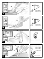
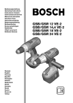
GHG 660 LCD
PROFESSIONAL
* Des idées en action.
Bedienungsanleitung
Operating instructions
Instructions d’utilisation
Instrucciones de servicio
Manual de instruções
Istruzioni d’uso
Gebruiksaanwijzing
Betjeningsvejledning
Bruksanvisning
Brukerveiledningen
Käyttöohje
Οδηγία χειρισµού
Kullan∂m k∂lavuzu
4
5
6
4
7
9
8
3
2
1
3
10
75 mm
50 mm
1 609 390 451
1 609 201 795
75 mm
50 mm
1 609 390 452
1 609 201 796
Ø 40 mm
1 609 390 453
HDPE
PVC (hard)
PVC (soft)
PP
LDPE
1 609 201 807
1 609 201 808
1 609 201 809
1 609 201 810
1 609 201 811
A
11
B
12
C
13
1 609 201 797
14
15
D
1 609 201 798
15
Ø 9 mm
Ø 14 mm
Ø 20 mm
1 609 201 797
1 609 201 647
1 609 201 648
16
Ø 2,4–4,8 mm 1 609 201 812
Ø 4,8–9,5 mm 1 609 201 813
E
Ø 40 mm
12
1 609 390 453
80 mm
1 609 201 751
Ø 9 mm
Ø 14 mm
Ø 20 mm
1 609 201 797
1 609 201 647
1 609 201 648
80 mm
1 609 201 751
F
15
G
Ø 40 mm
1 609 390 453
Product Specifications
Hot Air Blower
GHG 660 LCD
PROFESSIONAL
GHG 660 LCD
PROFESSIONAL
Order number
0 601 944 7..
0 601 944 7..
Voltage
[V] 220–240
Rated input power max.
110–120
[W] 2300
Air flow approx.
1400
[l/min] 250 ... 500
250 ... 500
[°C] 50 ... 660
50 ... 600
Temperature at nozzle outlet approx.
Temperature measuring accuracy
at the nozzle outlet
on the display
±5 %
±5 %
±5 %
±5 %
Display operating temperature*
[°C] –20 ... +70
–20 ... +70
Weight without mains cable approx.
[kg] 1.0
1.0
Protection class
/ II
/ II
* Outside of the operating temperature, the display can become black.
Please observe the order number of your unit. The trade names of the individual units may vary.
Noise Information
Intended Use
Measured values determined according to EN 50 144.
Typically the A-weighted sound pressure level of the
product is less than 70 dB(A).
The unit is intended for the forming and welding of
plastic, removal of paint and the warming of heatshrinkable tubing.
It is also suitable for soldering and tinning, loosening of
adhesive joints and the defrosting of water lines.
Product Elements
1
2
3
4
5
6
7
8
9
10
11
12
13
14
15
16
For Your Safety
Working safely with this unit is possible only when the operating and
safety information are read completely and the instructions contained therein are strictly followed.
Nozzle
Heat protection
On-off switch/selector switch
Cover with dust filter
Program selection button “P”
Display
Button for setting the air flow
Button for setting the temperature
Store button
Wide nozzle*
Glass protection nozzle*
Reflector nozzle*
Welding rod*
Welding shoe*
Reduction nozzle*
Heat-shrinkable tubing*
The workplace should be well ventilated. Gases and vapours that occur are
frequently detrimental to health.
■
■
The unit must not be damp and must also not be
operated in damp surroundings.
Before each use of the unit, check the cable and
plug. If damage is detected, do not use the unit.
Have repairs performed only by a qualified technician. Never open the unit yourself.
* Not all the accessories illustrated or described are included in standard delivery.
1 609 929 F39 • (03.10) T
English–1
■
Connect units that are used in the open via a residual current device (RCD) with an actuating current
of 30 mA maximum. Do not operate the unit in rain
or moisture.
■
Do not carry or hang up the unit by the cable.
■
Always direct the cable to the rear away from the
unit.
■
If the cable is damaged or cut through while working, do not touch the cable but immediately pull the
mains plug. Never use the unit with a damaged cable.
■
Do not operate the unit unattended.
■
During pauses in the work, when not in use or during work on the unit itself (e.g., changing of the
working tools, repairs, cleaning, adjustment), pull
the mains plug.
■
Wear safety glasses.
■
The strong heating effect (e.g. as a result of careless handling) of this unit increases the danger of
fire and explosion!
■
When working with plastics, paints, lacquers and
similar materials, combustible and poisonous gases can occur. Do not work in the vicinity of easily
combustible gases or materials.
■
The heat can reach flammable parts that are located outside of the visible area.
■
Do not point the unit for a long period at one spot.
■
Danger of burning! Do not touch the hot nozzle.
Wear protective gloves.
■
Never direct the air stream at persons or animals.
■
Never use the unit as a hair dryer.
■
Do not hold the nozzle outlet too close to the workpiece to be heated. The resulting restriction in the
air flow can lead to overheating of the unit.
■
Allow the unit to cool completely before storing.
The hot nozzle can cause damage.
■
Never allow children to use the unit.
■
Bosch is able to ensure flawless functioning of the
unit only if the original accessories intended for it
are used.
Putting into Operation
Ensure that the mains voltage is correct!
The voltage of the power source must agree with the
value given on the nameplate of the unit. Units designated for 230 V can also be operated with 220 V.
Switching On/Off
To put into operation, slide the on/off switch 3 to the
position
or .
In both positions, the unit starts with the air flow and
temperature values that were set before the last
switch-off.
To switch off, slide the on/off switch 3 to the stop at
position O.
After working for a longer time with high temperature,
allow the unit to cool by running in the cold air setting
before switching off.
Thermo-Protection Switch-Off
When the heater is overloaded (e.g. as a result of restricted air flow), the unit switches it off automatically,
however, the blower continues to run. When the unit
has cooled to operating temperature, the heater is
switched on again.
Cold Air Setting
The air flow can be regulated, the temperature is fixed at 50 °C (cannot be regulated), no programmed operation is possible
The cold air setting
is suitable for cooling a warmed
work piece or for the drying of paint. It is also suitable
for cooling the unit before placing down or the changing of nozzles.
When changing from the hot air setting with high
temperatures to the cold air setting , a short time is
required until the unit cools down to 50 °C. During this
cooling period, the actual temperature of the nozzle
outlet is shown in the display 6.
When changing from the hot air setting to the cold air
setting , the current air flow setting is taken over.
Hot Air Setting
The air flow and temperature can be regulated, normal and programmed operation is possible
For applications see Working Examples.
When changing from the cold air setting
to the hot
air setting , air flow, temperature, operating mode and
program are automatically set as they were when the
hot air setting was last used.
1 609 929 F39 • (03.10) T
English–2
Setting the Air Flow
The air flow can be regulated with the air flow button 7.
Pre-Stored Programs
The unit is delivered with the following four programs:
Minimum air flow (approx. 250 l/min)
Application
Shaping of plastic
tubing (e.g. LDPE)
Welding of plastic
(e.g. PVC)
Removing paint/
softening adhesives
Soldering
Maximum air flow (approx. 500 l/min)
The air flow can be increased by pressing the “+” side
of the air flow button 7 or decreased by pushing the “–”
side of the button 7. Brief pressing of the button increases or decreases the air flow by one step. Longer
pressing of the button increases or decreases the air
flow continuously until the maximum or minimum air flow
is reached.
Decrease the air flow when, for example:
– The surroundings of the work piece should not be
heated more than necessary
– A light work piece could be blown away by the air
stream.
Setting the Temperature
The temperature in the hot air setting can be regulated.
For changes to another temperature, the unit needs a
short time to warm or cool the air stream to the target
temperature. The target temperature is shown in the
display 6 during this time with blinking arrows
.
After reaching the required temperature, the arrows
are eliminated and the display 6 shows the actual
temperature.
The target temperature can be increased in steps of
10 °C by pressing the “+” side of the temperature button 8 or reduced by pressing the “–” side of the button
8. Brief pressing of the button increases or decreases
the target temperature one time by 10 °C. Longer
pressing of the button increases or decreases the
temperature continuously by 10 °C steps until the button is released or the minimum or maximum temperature is reached.
Operating Modes
Programmed Operation
In programmed operation, air flow and temperature
settings can be stored in four programs. In each program, any air flow and temperature combination is
possible.
Also in programmed operation, air flow and temperature can be changed at any time. If the changes are
not stored, they are lost when switching off or when
changing to another program.
To change to the programmed mode, press the program selection button “P” 5 until the number of the required program ( , ,
or ) is shown in the display.
1 609 929 F39 • (03.10) T
Temperature Air Flow
250 °C
350 °C
450 °C
550 °C
Changing of Programs
Press the program selection button “P” 5 until the
number of the program to be changed is shown in the
display. Set the required temperature and air flow (see
Sections Setting the Air Flow and Setting the Temperature). As soon as the values of the program are
changed, the symbol
blinks in the upper left of the
display.
After setting the required air flow and temperature,
hold the store button
9 depressed until the symbol
in the display disappears. The values set are now
stored under the program number shown in the display.
Normal Operation
To change to normal operation, press the program selection button “P” 5 repeatedly until there is no longer
a program number shown over the temperature in the
display.
The air flow and temperature can now be changed at
any time.
The last set values for the air flow and temperature remain stored under the following conditions:
– Change to program operation
– Change to the cold setting
– Switch-off of the unit.
Working Instructions
Removing the Heat Protector
For working in especially narrow places, the heat protector 2 can be removed.
■
Be careful of the hot nozzle! Increased danger
of burning exists when working without the heat
protector.
To remove or mount the heat protector, the unit must
be switched off and have cooled. For cooling, run
briefly in the cold setting, if necessary.
Turn the heat protector 2 counter clockwise to remove
and clockwise to mount again.
English–3
Placing Down the Unit
For cooling of the heated unit or to have both hands
free for working, the unit can be place down in the upright position on the rear housing surface (see Fig. C ).
■
Be especially careful when working with the
upright unit! There is danger of burning on the hot
nozzle and the hot air stream.
D Welding Plastics
Place on the reduction nozzle 15 and the welding shoe
14. The materials to be welded and the welding rod
13 must be made of the same material (e.g. PVC
with PVC). The seam must be clean and grease-free.
Heat the welding seam until it becomes tacky. Please
note that the temperature difference between the
tacky and liquid state of a plastic is very small. Then
feed in the welding rod 13 and allow to run into the gap
so that a uniform bead is produced.
Working Examples
The letters of the following application examples refer
to the illustrations on the fold-out page.
Temperature settings given in the application examples are suggested values that, depending on the material characteristics, can deviate. The distance between the nozzle and workpiece is dependent on the
material to be processed.
The ideal temperature should first be ascertained by
performing a test. Therefore, begin with a lower temperature setting.
All application examples (except B ) can be performed
without accessories. However, the use of the recommended accessory parts simplify the work and significantly improve the quality of the results.
■
Be careful when changing the nozzle, danger
of burning! Do not tough the hot nozzle. Allow
the unit to cool. Wear protective gloves.
Bosch stocks an extensive range of accessories (see
Bosch Accessories catalogue) which offer a wide
range of other applications.
A Removing Paint/Softening Adhesives
Place on the wide nozzle 10. Soften the paint using
hot air and remove evenly using a spatula. Do not heat
the paint for too long since this will burn the paint,
making it more difficult to remove. The spatula should
be kept sharp and clean.
Many adhesives (e.g. stickers) become softer when
heated allowing adhesive bonds to be separated or
superfluous adhesive to be removed.
Removing Paint from Window Frames
Danger of glass breaking!
Use of the glass protection nozzle 11 is essential.
On profiled surfaces, paint can be removed using a
spatula and brushed off using a soft wire brush.
B
Shaping Plastic Tubing
Place on the reflector nozzle 12. To avoid kinking the
tubing, fill the tubing with sand and seal at both ends.
Heat the tubing evenly by moving it from side to side.
C
1 609 929 F39 • (03.10) T
E Shrink Fitting
Place on the reduction nozzle 15. Select the diameter
of the heat-shrink tubing 16 according to the work
piece, for example, a cable lug.
Heat the heat-shrinkable sleeve evenly.
Defrosting Water Pipes
Water lines often do not differ in appearance from gas lines. Gas lines are not to
be heated under any circumstances.
Place on the reflector nozzle 12. Heat the frozen zone
always from the outside to the middle.
Warm plastic pipes as well as connections between
pipe pieces especially carefully to prevent damage.
F
G Soft Soldering
For point soldering, place on the reduction nozzle 15,
for the soldering of pipes, the reflector nozzle 12.
If solder without flux is used, apply soldering grease or
paste to the location to be soldered. Warm the location to be soldered for 50–120 s depending on the
material. Apply the solder. The solder must melt from
the work piece temperature.
After the soldered location has cooled, remove the
flux.
Maintenance and Cleaning
■
■
Before any work on the unit itself, pull the mains
plug.
For safe and efficient working, always keep the unit
and the ventilation slots clean.
Cleaning the Dust Filter
Slide the cover 4 containing the dust filter to the rear
out of the housing. Blow out the dust filter (with compressed air for example) or clean with a soft brush.
Replace the cover.
English–4
WARNING
Important instructions for connecting a new 3pin plug to the 2-wire cable.
The wires in the cable are coloured according to the
following code:
Strain relief
Live = brown
Neutral = blue
To be fitted
by qualified
professionals only
Do not connect the blue or brown wire to the earth terminal of the plug.
Important: If the plug on the cable of this unit must
be replaced, dispose of the old plug to prevent misuse.
If the unit should fail despite the care taken in manufacture and testing, repair should be carried out by an
authorised customer services agent for Bosch power
tools.
For all correspondence and spare parts orders, always
include the 10-digit order number of the unit.
Ireland
Beaver Distribution Ltd.
Greenhills Road
Tallaght-Dublin 24
✆ Service . . . . . . . . . . . . . . . .
+ 353 (0)1/414 9400
Fax . . . . . . . . . . . . . . . . . . . . . + 353 (0)1/459 8030
Australia
Robert Bosch Australia L.t.d.
RBAU/SBT2
1555 Centre Road
P.O. Box 66 Clayton
3168 Clayton/Victoria
✆ . . . . . . . . . . . . . . . . . . . . . +61 (0)1/800 804 777
Fax . . . . . . . . . . . . . . . . . . . . +61 (0)1/800 819 520
www.bosch.com.au
E-Mail: [email protected]
New Zealand
Robert Bosch Limited
14-16 Constellation Drive
Mairangi Bay
Auckland
New Zealand
✆ . . . . . . . . . . . . . . . . . . . . . . . +64 (0)9/47 86 158
Fax . . . . . . . . . . . . . . . . . . . . . . +64 (0)9/47 82 914
Declaration of Conformity
Environmental Protection
Recycle raw materials instead of
disposing as waste.
The unit, accessories and packaging
should be submitted for environmentfriendly recycling.
These instructions are printed on recycled paper manufactured without chlorine.
The plastic components are labelled for categorised
recycling.
We declare under our sole responsibility that this product is in conformity with the following standards or
standardization documents:
EN 60 335 according to the provisions of the directives 73/23/EEC, 89/336/EEC.
03
Dr. Egbert Schneider
Senior Vice President
Engineering
Dr. Eckerhard Strötgen
Head of Product
Certification
Service and Customer Advice
Exploded views and information on spare parts can be
found under: www.bosch-pt.com.
Great Britain
Robert Bosch Ltd. (B.S.C.)
P.O. Box 98
Broadwater Park
North Orbital Road
Denham-Uxbridge
Middlesex UB 9 5HJ
✆ Service . . . . . . . . . . . . . . .+44 (0) 18 95/83 87 82
✆ Advice line. . . . . . . . . . . . .+44 (0) 18 95/83 87 91
Fax . . . . . . . . . . . . . . . . . . . .+44 (0) 18 95/83 87 89
1 609 929 F39 • (03.10) T
Robert Bosch GmbH, Geschäftsbereich Elektrowerkzeuge
Specification subject to alteration without notice
English–5