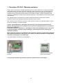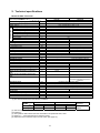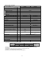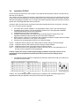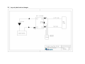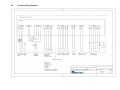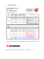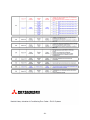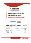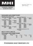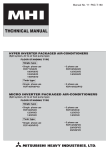
1
Technical manual
FD-PAC
Controlkit, R410A
(FDC71-250V/FD-PAC)
Version 01/10
Read this user manual carefully before installation and operation of this
equipment.
Store this manual together with the other user and technical manuals of the
Airconditioning equipment!
All mentioned measures and safety instructions must be strictly complied with.
The outdoor unit and connected equipment does contain refrigerant R410a.
Safety instructions
General Information, Risks in Non-Compliance with the Safety Instructions
The instructions contain basic notes to be followed during installation and operation. It therefore must
be read by the installation staff and personnel in charge before installation and initial operation. Wrong
and improper installation can result in fatal accidents or damage to the system! No liability is born if via
the circuit board contacts other devices/components are activated as additional circuit boards! Noncompliance with the safety instructions poses a risk to the personnel, environment and this system.
Failure to comply with the safety instructions will result in the loss of any claims.
Working with refrigerant
When working with refrigerant the following conditions must be complied:
- Inhaling big amounts of refrigerant will have a anesthetic effect;
- Refrigerant in gas form is heavier the air and can collect at lower levels. This can create
choking hazard;
- Always works with glasses and handgloves during handling refrigerant;
- Do not eat, drink and smoke when handling refrigerant;
- Refrigerant can cause injury when contacting human skin;
- Refrigerant must be handled in ventilated areas only;
- In case of accidents first help must be warned.
Qualified Personnel, Training and Safety-Oriented Working
The personnel in charge with the installation and operation must be properly qualified for these works.
Defects due to improper installation can cause electric power accidents or fires! The safety
instructions mentioned in the installation guidelines, the applicable national laws regarding accident
prevention and internal work, operational and safety instructions must be noted and strictly followed
without exception.
Safety Instructions on Maintenance, Inspection and Installation Works
The operator must ensure that all maintenance, inspection and installation works are carried out by
authorised and qualified expert personnel that have been thoroughly informed by studying the
installation guidelines. Any works on the system must be performed in idle state. The instructions
described in the operating manual on idling the system must be absolutely complied with.
The machine/system must be made currentless for any works and secured with a warning sign against
unintentional switching on. The machine and/or system must be checked if it is free from current.
Before taking it back into operation the measures outlined under "Assembly/Operation" must be noted
and followed. Any electric works must be carried out by qualified expert personnel complying with all
safety regulations on electric equipment, applicable local regulations and installation guidelines. Only
divided circuits may be used. Improper electric connections can cause serious accidents and fires.
- 2-
The electric connections must always be made with suitable cables, and it must be ensured that the
cables are properly secured to prevent any mechanical forces on the cables from affecting the cable
connections inside the machine. A faulty cable connection can develop heat inside the machine and/or
cause fires. It must be ensured that electric lines cannot be damaged by lids/maintenance covers. A
faulty installation of the maintenance cover can also develop heat inside the machine and/or cause
fires.
Impermissible Operation
Safe operation of the system is only ensured if it is used in accordance with regulations and
instructions. The limit values given in the technical specification must never be exceeded.
- 3-
Content
1 Descripton FD-PAC / Warranty exclusion
5
2 Technical specifications
6
3 Installation
3.1 Safety instructions
3.2 Installation FD-PAC
3.3 Lay out plate heat exchanger
3.4 Lay out heat exchanger
3.5 Lay out electrical wiring diagram
12
12
14
15
16
17
4 Troubleshooting
18
- 4-
1. Descripton FD-PAC / Warranty exclusion
Control kit for connecting an optional heat exchanger on a FDC outdoor unit for cooling and heating
(refrigerant R410A).The control kit is fully wired and contain the electronics with microprocessor for
communication with the FDC outdoor unit. The selfdiagnose system provides a fast recognition of
problems and provides alpha numeric codes on the remote controller. Via DIP switches the PCB
needs to be configured in relation with the optional equipment. The temperature sensors are included
in this delivery.
The equipment will be controlled via a remote controller with actual time and timer functions,
ventilation selections and operation/warning connections (CNT contact).
The control kit can be switched on/off via an external 230V AC signal. Via optional PCB’s the control
kit can be combined in a central controller.
Caution: The manufacturer is obliged to give warranty on the delivered components and
therefor not responsible for the operation and control of the equipment which is connected to
the control kit FD-PAC!
Furthermore there is no warranty or a possibility to claim ensuing damage which is the result
of wrong calculation, selection of heat exchangers, positioning of sensors, planning and
installation mistakes.
When using the control kit in combination with cold water equipment via plate heat exchangers
there must be a minimum of 15% glycol in the system. For other constructions or applications
a minimum of 15% glycol is recommended.
The pictures below can differ from actual delivery.
Control kit
FD-PAC
Optional remote controller
RC-E3 (not included)
Technical specifications and maximum values are mentioned on the next pages.
- 5-
2. Technical specifications
Model FD-PAC / FDC71VN
Model
Technical specifications
Operation data (3)
Nominal coolingcapacity (1)
Nominal heating capacity (1)
Power source
Cooling power consumption
Running current (cooling)
Power factor (cooling)
Heating power consumption
Running current (heating)
Power factor (heating)
Inrush current
Moise level
Exterior dimensions (height x width x depth)
Nett weight
Compressor type
Compressor motor
Refrigerant oil
Carterheating
Starting method
Heat exchanger
Defrost control
Refrigerant
Refrigerant amount
Refrigerant expansion
Air handling equipment, fan type
Motor
Air flow
Air entrance temperature cooling min./ max.
Air entrance temperature heating min./ max.
Water entrance temperature cooling min./
max.
Water entrance temperature heating min./
max.
Safety equipment
Control kit
Outdoor unit
FD-PAC
FDC71VN
W
W
7100 (3200 ~ 8000)
8000 (3600 ~ 9000)
1 fase, 220/230/240V, 50Hz, N, PE
2,01/2,01
8,9/9,2
98/99
2,21/2,21
9,8/10,2
99
5,0
kW
A
%
kW
A
%
A
dB(A)
mm
Kg
48
400 x 300 x 120
750 x 968 x 340
8
60
(M-MA32R)
33 (carterheating)
Direct
Air (straight fin)
Microprocessor controller de-icer
R410A
2,95 (pre-charged to 30 mtr)
Elektronic expansion valve
Axial fan x 1
55 x 1
Min.1200
3600
16 / 32
10 / 32
16 / 32
-
kW
L
W
kg
m³/h
°C
°C
°C
°C
10 / 32
-
Internal thermostat for fanmotor,
anomalous discharge temperature
protection
Liquid line 10mm, Gas line 16mm
Liquid line 9,52 mm (3/8”), Gas line 15,88mm (5/8”)
Flare piping
Necessary (liquid and gasline)
Drain pan3x Ø20 mm
RC-E3
-
Refrigerant piping
Piping size
Connecting method
Isolation
Drain hose
Accessoires
Paneel (separate packing)
Optional accessoires
Remote controller
mm
mm
mm
Notes
(1) The data are measured at the following conditions.
Item
Mode
Cooling
Heating
Indoor temperature
d.b. temp.
w.b. temp.
27°C
19°C
20°C
-
Outdoor temperature
d.b. temp.
w.b. temp.
35°C
24°C
7°C
6°C
standard
ISO-T1, JIS
B8616
(2) This airconditioner is manufactured and tested in conformity with the following standards: ISO-T1”unitary
airconditioner”.
(3) The operation data indicate when the airconditioner is operated at 230V, 50hz.
(4) Values in ( ~ ) show the minimum to maximum range.
(5) Adjustment of the estimated output via DIP switch (see page 16).
- 6-
Model FD-PAC / FDC100VS
Model
Technical specifications
Outdoor unit
FD-PAC
FDC100VS
10000 (6100 ~ 11200)
11200 (5600 ~ 12500)
1 fase, 220/230/240V, 50Hz, N, PE
2,85/2,85
12,5/13,1
99/99
2,97/2,97
13,0/13,6
99/99
5,0
Operation data (3)
Nominal coolingcapacity (1)
Nominal heating capacity (1)
Power source
Cooling power consumption
Running current (cooling)
Power factor (cooling)
Heating power consumption
Running current (heating)
Power factor (heating)
Inrush current
Moise level
Exterior dimensions (height x width x depth)
Nett weight
Compressor type
Compressor motor
Refrigerant oil
Carterheating
Starting method
Heat exchanger
Defrost control
Refrigerant
Refrigerant amount
Refrigerant expansion
Air handling equipment, fan type
Motor
Air flow
Air entrance temperature cooling min./ max.
Air entrance temperature heating min./ max.
Water entrance temperature cooling min./
max.
Water entrance temperature heating min./
max.
Safety equipment
Control kit
50
400 x 300 x 120
845 x 970 x 370
8
74
RM-B5125MD11
2,4
0,9 (M-MA68)
20 (carterheating)
Direct
Air (straight fin)
Microprocessor controller de-icer
R410A
3,8 (pre-charged to 30 mtr)
Elektronic expansion valve
Axiaal ventilator x 1
120 x 1
Min.1600
4500
16 / 32
10 / 32
16 / 32
10 / 32
-
Internal thermostat for fanmotor,
anomalous discharge temperature
protection
Liquid line 10mm, Gas line 16mm
Liquid line 9,52 mm (3/8”), Gas line 15,88mm (5/8”)
Flare piping
Necessary (liquid and gasline)
Drain pan3x Ø20 mm
RC-E3
-
Refrigerant piping
Piping size
Connecting method
Isolation
Drain hose
Accessoires
Paneel (separate packing)
Optional accessoires
Remote controller
Notes
(1) The data are measured at the following conditions.
Item
Mode
Cooling
Heating
Indoor temperature
d.b. temp.
w.b. temp.
27°C
19°C
20°C
-
Outdoor temperature
d.b. temp.
w.b. temp.
35°C
24°C
7°C
6°C
standard
ISO-T1, JIS
B8616
(2) This airconditioner is manufactured and tested in conformity with the following standards: ISO-T1”unitary
airconditioner”.
(3) The operation data indicate when the airconditioner is operated at 230V, 50hz.
(4) Values in ( ~ ) show the minimum to maximum range.
(5) Adjustment of the estimated output via DIP switch (see page 16).
- 7-
Model FD-PAC / FDC125VS
Model
Technical specifications
Operation data (3)
Nominal coolingcapacity (1)
Nominal heating capacity (1)
Power source
Cooling power consumption
Running current (cooling)
Power factor (cooling)
Heating power consumption
Running current (heating)
Power factor (heating)
Inrush current
Moise level
Exterior dimensions (height x width x depth)
Nett weight
Compressor type
Compressor motor
Refrigerant oil
Carterheating
Starting method
Heat exchanger
Defrost control
Refrigerant
Refrigerant amount
Refrigerant expansion
Air handling equipment, fan type
Motor
Air flow
Air entrance temperature cooling min./ max.
Air entrance temperature heating min./ max.
Water entrance temperature cooling min./
max.
Water entrance temperature heating min./
max.
Safety equipment
Refrigerant piping
Piping size
Connecting method
Isolation
Drain hose
Accessoires
Paneel (separate packing)
Optional accessoires
Remote controller
W
W
Control kit
Outdoor unit
FD-PAC
FDC125VS
12500 (5000 ~ 14000)
14000 (4000 ~ 16000)
1 fase, 220/230/240V, 50Hz, N, PE
4,10/4,10
18,0/18,8
99/99
3,65/3,65
16,0/16,8
99/99
5,0
kW
A
%
kW
A
%
A
dB(A)
mm
Kg
50
400 x 300 x 120
845 x 970 x 370
8
74
RM-B5125MD11
2,5
0,9 (M-MA68)
20 (carterheating)
Direct
Air (straight fin)
Microprocessor controller de-icer
R410A
3,8 (pre-charged to 30 mtr)
Elektronic expansion valve
Axiaal ventilator x 1
120 x 1
Min.2000
4500
16 / 32
10 / 32
16 / 32
-
kW
L
W
kg
m³/h
°C
°C
°C
°C
10 / 32
-
Internal thermostat for fanmotor,
anomalous discharge temperature
protection
Liquid line 10mm, Gas line 16mm
Liquid line 9,52 mm (3/8”), Gas line 15,88mm (5/8”)
Flare piping
Necessary (liquid and gasline)
Drain pan3x Ø20 mm
RC-E3
-
mm
mm
mm
Notes
(1) The data are measured at the following conditions.
Item
Mode
Cooling
Heating
Indoor temperature
d.b. temp.
w.b. temp.
27°C
19°C
20°C
-
Outdoor temperature
d.b. temp.
w.b. temp.
35°C
24°C
7°C
6°C
standard
ISO-T1, JIS
B8616
(2) This airconditioner is manufactured and tested in conformity with the following standards: ISO-T1”unitary
airconditioner”.
(3) The operation data indicate when the airconditioner is operated at 230V, 50hz.
(4) Values in ( ~ ) show the minimum to maximum range.
(5) Adjustment of the estimated output via DIP switch (see page 16).
- 8-
Model FD-PAC / FDC140VS
Model
Technical specifications
Operation data (3)
Nominal coolingcapacity (1)
Nominal heating capacity (1)
Power source
Cooling power consumption
Running current (cooling)
Power factor (cooling)
Heating power consumption
Running current (heating)
Power factor (heating)
Inrush current
Moise level
Exterior dimensions (height x width x depth)
Nett weight
Compressor type
Compressor motor
Refrigerant oil
Carterheating
Starting method
Heat exchanger
Defrost control
Refrigerant
Refrigerant amount
Refrigerant expansion
Air handling equipment, fan type
Motor
Air flow
Air entrance temperature cooling min./ max.
Air entrance temperature heating min./ max.
Water entrance temperature cooling min./
max.
Water entrance temperature heating min./
max.
Safety equipment
Refrigerant piping
Piping size
Connecting method
Isolation
Drain hose
Accessoires
Paneel (separate packing)
Optional accessoires
Remote controller
W
W
Control kit
Outdoor unit
FD0-PAC
FDC140VS
14000 (5000 ~ 14500)
16000 (4000 ~ 16500)
1 fase, 220/230/240V, 50Hz, N, PE
4,98/4,98
22,0/23,0
98/98
4,69/4,69
20,5/21,5
99
5,0
kW
A
%
kW
A
%
A
dB(A)
mm
Kg
51
400 x 300 x 120
845 x 970 x 370
8
74
RM-B5125MD11
2,6
0,9 (M-MA68)
20 (carterheating)
Direct
Air (straight fin)
Microprocessor controller de-icer
R410A
3,8 (pre-charged to 30 mtr)
Elektronic expansion valve
Axiaal ventilator x 1
120 x 1
Min.2000
4500
16 / 32
10 / 32
16 / 32
-
kW
L
W
kg
m³/h
°C
°C
°C
°C
10 / 32
-
Internal thermostat for fanmotor,
anomalous discharge temperature
protection
Liquid line 10mm, Gas line 16mm
Liquid line 9,52 mm (3/8”), Gas line 15,88mm (5/8”)
Flare piping
Necessary (liquid and gasline)
Drain pan3x Ø20 mm
RC-E3
-
mm
mm
mm
Notes
(1) The data are measured at the following conditions.
Item
Mode
Cooling
Heating
Indoor temperature
d.b. temp.
w.b. temp.
27°C
19°C
20°C
-
Outdoor temperature
d.b. temp.
w.b. temp.
35°C
24°C
7°C
6°C
standard
ISO-T1, JIS
B8616
(2) This airconditioner is manufactured and tested in conformity with the following standards: ISO-T1”unitary
airconditioner”.
(3) The operation data indicate when the airconditioner is operated at 230V, 50hz.
(4) Values in ( ~ ) show the minimum to maximum range.
(5) Adjustment of the estimated output via DIP switch (see page 16).
- 9-
Model FD-PAC / FDC200VS
Model
Technical specifications
Operation data (3)
Nominal coolingcapacity (1)
Nominal heating capacity (1)
Power source
Cooling power consumption
Running current (cooling)
Power factor (cooling)
Heating power consumption
Running current (heating)
Power factor (heating)
Inrush current
Moise level
Exterior dimensions (height x width x depth)
Nett weight
Compressor type
Compressor motor
Refrigerant oil
Carterheating
Starting method
Heat exchanger
Defrost control
Refrigerant
Refrigerant amount
Refrigerant expansion
Air handling equipment, fan type
Motor
Air flow
Air entrance temperature cooling min./ max.
Air entrance temperature heating min./ max.
Water entrance temperature cooling min./
max.
Water entrance temperature heating min./
max.
Safety equipment
Refrigerant piping
Piping size
Connecting method
Isolation
Drain hose
Accessoires
Paneel (separate packing)
Optional accessoires
Remote controller
W
W
Control kit
Outdoor unit
FD-PAC
FDC200VS
20000 (7000 ~ 22400)
22400 (7600 ~ 25000)
3 fase, 380/400/415V, 50Hz, N, PE
6,47/6,47
9,7/10,1
96/97
5,97/5,97
9,1/9,5
95/95
5,0
kW
A
%
kW
A
%
A
dB(A)
mm
Kg
57
400 x 300 x 120
1300 x 970 x 370
8
122
GT-C5150ND79
4,5
1,45 (M-MA32R)
40 (carterheating)
Direct
Air (straight fin)
Microprocessor controller de-icer
R410A
5,4 (pre-charged to 30 mtr)
Elektronic expansion valve
Axiaal ventilator x 2
120 x 2
Min.3000
9000
16 / 32
10 / 32
16 / 32
-
kW
L
W
kg
m³/h
°C
°C
°C
°C
10 / 32
-
Internal thermostat for fanmotor,
anomalous discharge temperature
protection
Liquid line 10mm, Gas line 16mm
Liquid line 9,52 mm (3/8”), Gas line 22,22mm (7/8”)
Flare piping
Necessary (liquid and gasline)
Drain pan3x Ø20 mm
RC-E3
-
mm
mm
mm
Notes
(1) The data are measured at the following conditions.
Item
Mode
Cooling
Heating
Indoor temperature
d.b. temp.
w.b. temp.
27°C
19°C
20°C
-
Outdoor temperature
d.b. temp.
w.b. temp.
35°C
24°C
7°C
6°C
standard
ISO-T1, JIS
B8616
(2) This airconditioner is manufactured and tested in conformity with the following standards: ISO-T1”unitary
airconditioner”.
(3) The operation data indicate when the airconditioner is operated at 230V, 50hz.
(4) Values in ( ~ ) show the minimum to maximum range.
(5) Adjustment of the estimated output via DIP switch (see page 16).
-10-
Model FD-PAC / FDC250VS
Model
Technical specifications
Operation data (3)
Nominal coolingcapacity (1)
Nominal heating capacity (1)
Power source
Cooling power consumption
Running current (cooling)
Power factor (cooling)
Heating power consumption
Running current (heating)
Power factor (heating)
Inrush current
Moise level
Exterior dimensions (height x width x depth)
Nett weight
Compressor type
Compressor motor
Refrigerant oil
Carterheating
Starting method
Heat exchanger
Defrost control
Refrigerant
Refrigerant amount
Refrigerant expansion
Air handling equipment, fan type
Motor
Air flow
Air entrance temperature cooling min./ max.
Air entrance temperature heating min./ max.
Water entrance temperature cooling min./
max.
Water entrance temperature heating min./
max.
Safety equipment
Refrigerant piping
Piping size
Connecting method
Isolation
Drain hose
Accessoires
Paneel (separate packing)
Optional accessoires
Remote controller
W
W
Control kit
Outdoor unit
FD-PAC
FDC250VS
25000 (10000 ~ 28000)
28000 (9500 ~ 31500)
3 fase, 380/400/415V, 50Hz, N, PE
9,01/9,01
13,5/14,1
96/97
8,05/8,05
12,2/12,8
95/96
5,0
kW
A
%
kW
A
%
A
dB(A)
mm
Kg
57
400 x 300 x 120
1505 x 970 x 370
8
140
GT-C5150ND79
4,8
1,45 (M-MA32R)
40 (carterheating)
Direct
Air (straight fin)
Microprocessor controller de-icer
R410A
7,2 (pre-charged to 30 mtr)
Elektronic expansion valve
Axiaal ventilator x 2
120 x 2
Min.4000
9000
16 / 32
10 / 32
16 / 32
-
kW
L
W
kg
m³/h
°C
°C
°C
°C
10 / 32
-
Ingebouwde thermostaat voor
ventilatormotor
Beveiliging voor te hoge
persgastemperatuur
Liquid line 10mm, Gas line 16mm
Liquid line 12,7mm (1/2”), Gas line 22,22mm (7/8”) (6)
Flare piping
Necessary (liquid and gasline)
Drain pan3x Ø20 mm
RC-E3
-
mm
mm
mm
Notes
(1) The data are measured at the following conditions.
Item
Mode
Cooling
Heating
Indoor temperature
d.b. temp.
w.b. temp.
27°C
19°C
20°C
-
Outdoor temperature
d.b. temp.
w.b. temp.
35°C
24°C
7°C
6°C
standard
ISO-T1, JIS
B8616
(2) This airconditioner is manufactured and tested in conformity with the following standards: ISO-T1”unitary
airconditioner”.
(3) The operation data indicate when the airconditioner is operated at 230V, 50hz.
(4) Values in ( ~ ) show the minimum to maximum range.
(5) Adjustment of the estimated output via DIP switch (see page 16).
(6) See technical manual “branch pipe set” for correction on size.
-11-
3.
Installation
3.1
SAFETY PRECAUTIONS
• Read the “SAFETY PRECAUTIONS” carefully first of all and then strictly follow it during the
installation work in order to protect yourself.The precautionary items mentioned below are
distinguished into two levels, WARNING and CAUTION.
WARNING: Wrong installation would cause serious consequences such as injuries or death.
CAUTION: Wrong installation might cause serious consequences depending on circumstances.
Both mentions the important items to protect your health and safety so strictly follow them by any
means.
• After completing the installation, do commissioning to confirm there are no abnormalities, and explain
to the customers about
“SAFETY PRECAUTIONS”, correct operation method and maintenance method (air filter cleaning,
operation method and temperature setting method) with userís manual of this unit. Ask your
customers to keep this installation manual together with the userís manual. Also, ask them to hand
over the user,s manual to the new user when the owner is changed.
WARNING
•
•
•
•
•
•
•
•
•
•
•
•
•
•
Installation should be performed by the specialist.
If you install the unit by yourself, it may lead to serious trouble such as water leakage, electric
shock, fire, and injury due to overturn of the unit.
Install the system correctly according to these installation manuals.
Improper installation may cause explosion, injury, water leakage, electric shock, and fire.
Consider measurement not to exceed the limit of the density of refrigerant in the event of
leakage especially when it is installed in a small room.
Consult the specialist about the measure. If the density of refrigerant exceeds the limit in the event
of the leakage, serious accidents may occur due to lack of oxygen.
Use the genuine accessories and the specified parts for installation.
If parts unspecified by our company are used it could cause water leakage, electric shock, fire,
and injury due to overturn of the unit.
Ventilate the working area well in case the refrigerant leaks during installation.
If the refrigerant contacts the fire, toxic gas is produced.
Install the unit in a location that can hold heavy weight.
Improper installation may cause the unit to fall leading to accidents.
Install the unit properly in order to be able to withstand strong winds such as typhoons,
and earthquakes.
Improper installation may cause the unit to fall leading to accidents.
Do not mix air in to the cooling cycle on installation or removal of the air conditioner.
If air is mixed in, the pressure in the cooling cycle will rise abnormally and may cause explosion
and injuries.
Be sure to have the electrical wiring work done by qualified electrical installer, and use
exclusive circuit.
Power source with insufficient capacity and improper work can cause electric shock and fire.
Use specified wire for electrical wiring, fasten the wiring to the terminal securely, and hold
the cable securely in order not to apply unexpected stress on the terminal.
Loose connections or hold could result in abnormal heat generation or fire.
Arrange the electrical wires in the control box properly to prevent them from rising. Fit the
lid of the services panel property.
Improper fitting may cause abnormal heat and fire.
Check for refrigerant gas leakage after installation is completed.
If the refrigerant gas leaks into the house and comes in contact with a fan heater, a stove, or an
oven, toxic gas is produced.
Use the specified pipe, flare nut, and tools for R410A.
Using existing parts (R22) could cause the unit failure and serious accident due to explosion of the
cooling cycle.
Tighten the flare nut according to the specified method by with torque wrench.
If the flare nut were tightened with excess torque, it could cause burst and refrigerant leakage after
a long period.
-12-
•
•
•
•
•
•
•
•
•
Make sure there is no dust or clogging on both the plug and the socket nor loose
connection of the socket before plugging, and plug in securely to the end of the blade.
Accumulation of dust, clogging on the socket or plug, or loose installation of the socket could
cause electric shock and fire. Replace the socket if it is loose.
Connect the pipes for refrigeration circuit securely in installation work before compressor
is operated.
If the compressor is operated when the service valve is open without connecting the pipe, it could
cause explosion and injuries due to abnormal high pressure in the system.
Stop the compressor before removing the pipe on pump down work.
If the pipe is removed when the compressor is in operation with the service valve open, air would
be mixed in the refrigeration circuit and it could cause explosion and injuries due to abnormal high
pressure in the cooling cycle.
Use the genuine optional parts. And installation should be performed by a specialist.
If you install the unit by yourself, it could cause water leakage, electric shock and fire.
Do not repair by yourself. And consult with the dealer about repair.
Improper repair may cause water leakage, electric shock or fire.
Consult the dealer or a specialist about removal of the air conditioner.
Improper installation may cause water leakage, electric shock or fire.
Turn off the power source during servicing or inspection work.
If the power is supplied during servicing or inspection work, it could cause electric shock and injury
by the operating fan.
Do not run the unit when the panel or protection guard are taken off.
Touching the rotating equipment, hot surface, or high voltage section could cause an injury to be
caught in the machine, to get burned, or electric shock.
Shut off the power before electrical wiring work.
It could cause electric shock, unit failure and improper running.
CAUTION
•
•
•
•
•
•
•
•
•
•
•
•
Ground the equipment. Do not connect the ground wire to gas piping, water piping, a lightning rod,
or telephone ground wires. It grounding is not performed correctly electric shock could occur.
Depending on the installation location, a circuit breaker may need to be installed. It a circuit
breaker is not installed, electric shock may occur.
Please follow this manual faithfully in performing installation work. Improper installation work can
cause abnormal vibrations and noise generation.
Do not install the equipment in areas where there is danger of flammable gas leaks. It such gas
does leak it could collect around the units and cause a fire.
Install the drain piping in accordance with the installation manual so that it properly discharges
waste water and is maintained at a temperature that prevents condensation.
Do not install the outdoor unit where winds from its fan blow directly onto a plant, etc. Winds can
affect adversely to the plant, etc.
Secure a space for inspection and maintenance as specified in the manual. An insufficient space
can result in an accident such as a fall from the installation point and a resultant personal injury.
When the outdoor unit is installed on a roof or at an elevated point, provide permanent ladders
and handrails along the access route and fences and handrails around the outdoor unit.
In tightening a flare nut, use a double spanner and observe the specified tightening torque. Care
must be taken so as not to overtighten a nut and damage the flare part. (Please refer to the
tightening torque) The loosening or damage of the flare part can cause a refrigerant gas leak and
a resultant lack-of-oxygen accident.
Please dress the refrigerant piping with a heat insulation material for prevention of dew
condensation. Improper heat insulation for prevention of dew condensation can cause the leaking
or dripping of water and a resultant soaking of household effects.
When refrigerant piping is completed, check its air-tighteness with nitrogen gas to make sure it
does not have a leak. A leak of refrigerant gas in a narrow room beyond the safety limit
concentration can cause a lack-of oxygen accident.
If the humidity exceeds 80% or the drain or piping become clogged, condensation from the indoor
unit could drip and cause damage. Please do not install the indoor units above items of furniture,
etc. that you do not want to get wet. Also, do not place items that youdo not want to get wet
underneath the indoor units.
-13-
3.2
Installation FD-PAC
All the required components for the FD-PAC in accordance with this delivery will be connected to the
terminal on the FD-PAC.
The control kit can be switched on/off via an external 230V AC signal. Due to the invertercontrol of the
outdoor unit it is recommended to control an external fan via the connections of the FD-PAC. See the
attached wiring diagram (chapter 3.5). For further information regarding safety and protection systems
please refer to the applicable MHI technical manual.
Connector CNT must be used in combination with optional equipment like the Cool-sign in. Damage
can occur if incorrect power is applied.
1. The control box must be installed on an appropriate location close to the heat exchanger;
2. Installation piping outdoor unit-heat exchanger: Please refer to the applicable installation
instructions/technical manual of the equipment;
3. Install filter/dryer (bi-flow) in the liquid line;
4. Install the electrical wiring in accordance with the wiring diagram. Please refer to the
applicable installation instructions/technical manual of the equipment;
5. When using the control kit in combination with cold water equipment via plate heat exchangers
there must be a minimum of 15% glycol in the system.
6. Positioning of the temperature sensors on the heat exchanger:
Thi-R1 –
Thi-R2 –
Thi-R3 –
Thi-A –
Install this sensor at approx. 80% after entrance (mode cooling) of heat exchanger.
Install this sensor at the entrance (mode cooling) of heat exchanger.
Install this sensor at the exit (mode cooling) of heat exchanger.
Install this sensor on an appropriate location in the return air or in the applicable room. A
free flow of air is required must be guaranteed!
Caution: Tighten the sensors sufficiently and apply insulation around the sensor! This to
guarantee a correct temperature measurement and to prevent severe damage to the
equipment!
7. The estimated output needs to be adjusted via DIP switch SW6 of the PCB on the FD-PAC in
accordance with this tabel:
Caution: The commisioning needs to be performed in accordance with commissioning protocol
regarding fluorized gas regulation and Kyoto protocol and local regulations.
-14-
3.3 Lay out plate heat exchanger
3.4
Lay out heat exchanger
3.4
Lay out wiring diagram
4.
Troubleshooting
-19-
-20-
-21-
-22-