1
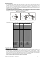
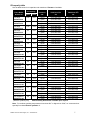
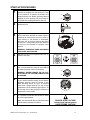
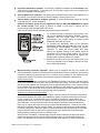
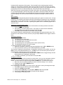
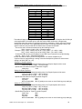
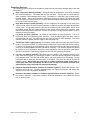
Installation
Operation
and
Maintenance
Manual
Lubricated and
lubricated for saturated air (wet) service
rotary vane vacuum pumps and systems
SERIAL NO:___________________________
Feb 2008/07
LUBRICATED ROTARY VANE VACUUM PUMPS AND SYSTEMS
TABLE OF CONTENTS
INTRODUCTION
Safety
STORAGE
INSTALLATION
Unpacking
Lifting
Location
Mounting
Ventilation
Electrical preparation
Pipe connections and sizing
Inlet piping
Discharge piping
THEORY OF OPERATION
Pump lubricant
Pumps for saturated air (wet) service
Gas ballast valve
Oil capacity table
START-UP PROCEDURES
SHUT-DOWN PROCEDURES
SEQUENCE OF OPERATION
SYSTEM ALARM CONDITIONS NFPA 99
MAINTENANCE
Pump oil level
Oil change
Devarnishing
Oil filter (if installed)
Inlet filter (if installed)
Exhaust filter
Bearings and seals
Bearing lubrication – Motor (where required)
MAINTENANCE SCHEDULE
First 8 hours operation
Daily
Weekly
500 hours operation
1000 hours operation
2000 hours operation
50,000 hours operation
ELECTRICAL CONTROLS
ACCESSORIES AND PROTECTIVE DEVICES
Accessories
Protective devices
TROUBLE SHOOTING
Trouble shooting FAQS
Start-stop problems
Vacuum problems
Overheating and smoking problems
Noise and vibration problems
High oil-consumption problems
CUSTOMER SERVICE AND INFORMATION
Order information
WARRANTY POLICY
Dekker Vacuum Technologies, Inc. – DuraVane/12
3
3
3
3
3
3
3
3
4
4
4
4
5
5
6
6
6
6
8
9
9
10
10
10
10
11
11
11
11
11
11
12
12
12
12
12
12
12
12
13
13
13
17
18
18
18
18
19
20
20
21
21
22
2
INTRODUCTION
DuraVane rotary vane vacuum pumps and systems haven been designed to give you safe, reliable
and trouble-free service, provided some of the basic maintenance guidelines as set out in this manual
are followed. A vacuum pump is a rotating piece of equipment and operators must exercise good
judgment and follow proper safety procedures to avoid damage to the equipment or personal injury.
Please review and follow all instructions in this manual before attempting to install, start or operate
equipment.
Safety
All products offered by DEKKER have been designed and manufactured for safe operation. However,
the responsibility for safe operation rests with those who use and maintain these products. Your safety
department should establish a safety program based on OSHA, federal, state and local codes. It is
important that due consideration be given to hazards which arise from the presence of electrical power,
hot liquids, toxic gases and rotating equipment. Proper installation and care of protective devices is
essential to safe pump and system operation. These safety procedures are to be used in conjunction
with the instructions contained in this manual.
STORAGE
Keep the pump or system in a cool, dry environment and plug all open ports to keep out dirt and
foreign objects.
INSTALLATION
The design of foundation, piping system and plant system design is the responsibility of the purchaser.
DEKKER Vacuum Technologies, Inc. and its representatives may offer advice but cannot assume
responsibility for operation and installation design.
Please consult an authorized dealer or a specialist skilled in the design of plant layout, system piping
design and foundation design. The installer should carefully read this manual before installing the
equipment. DEKKER or your local dealer can provide start-up assistance in most instances at
reasonable cost.
Unpacking
Upon receipt of pump or system, immediately inspect for signs of damage. Carefully remove the
packing or crating from around the pump or system. Be sure to keep equipment in the upright position.
DEKKER products are shipped F.O.B. factory, which means that any damage is the responsibility of
the carrier and should be reported to them.
Lifting
Lift the equipment carefully and with weight evenly distributed. DEKKER is not responsible for
equipment that has been damaged through mishandling or dropping.
Location
Install the unit in a well ventilated and dust free area. The pump or system should be a minimum
distance of 3 feet from surrounding walls to allow for checking fluid level, temperatures, pressures and
general servicing.
Whenever the pump is transported, be sure to drain the oil to avoid damage to the vanes when the
pump is restarted. Do not tip pump over if filled with oil.
Mounting
The pump or system must be installed on a level surface in a horizontal position. The foundation must
be designed to support the total unit weight without any settlement or crushing, be rigid and substantial
enough to absorb any equipment vibration, maintain true alignment with any drive mechanism, and
must permanently support the system base plate at all points.
The vacuum system must be leveled and secured with foundation bolts. Foundation bolts must be of
adequate size to withstand the mechanical stresses exerted on it.
Systems larger than 40hp should also be grouted into position. The foundation should be constructed
to allow for ¾ to 1 ½ inch of grout. The baseplate is set on shims, and the grout is poured between the
foundation and the base plate. To have the required strength to support the baseplate, the grout
should be at least ¾ inch thick.
Dekker Vacuum Technologies, Inc. – DuraVane/12
3
The number and location of shims will be determined by the design of the baseplate. Firm support
should be provided at points where weight will be concentrated at the anchor bolt locations. Use
enough, and large enough shims to provide rigid support. Baseplates are usually designed with
openings to allow pouring grout. When the baseplate has been shimmed and leveled, and the anchor
bolts have been snugly tightened, a dam is constructed around the foundation to contain the grout.
The dam level should be at least ½ inch above the top surface of the shims. Grout should be poured
inside and around the outside of the base plate and leveled. Allow the grout to dry for a minimum of 48
hours before tightening the anchor bolts.
Please note that the pump/motor coupling and V-belt units will need to be realigned prior to
startup, except with monoblock units.
Ventilation
Locate the pump or system in an area with sufficient airflow and accessibility. To prevent excessive
ambient temperature rise, it is imperative to provide adequate ventilation. Cooling is an important
aspect of reliable equipment operation and it is therefore important to install the unit in a reasonably
o
o
cool area, where temperatures do not exceed 100 F (38 C). For higher ambient temperatures, contact
the factory.
Electrical Preparation
All system wiring is performed at the factory if a control panel is supplied. Check area classification to
ensure all electrical enclosures comply to code. Required customer wiring is minimal, but should be
done by a qualified electrician in compliance with OSHA, National Electric Code and applicable local
electric code concerning isolation switches, fused disconnects, etc. DEKKER includes a wiring diagram
in the control panel for use by the installer. DEKKER recommends that a main disconnect switch be
fitted between the vacuum pump or system and the incoming power.
After the electrical wiring connections are completed, check the incoming voltage to make sure that the
incoming voltage is the same as the pump or system voltage. Line voltage should be within the voltage
tolerance as specified on the motor. Check the unit for proper motor rotation. The direction of rotation
is marked by an arrow on the motor or pump housing. Jog the motor by pressing the START button,
then the STOP button. If the rotation is incorrect, switch any two of the three main power leads on the
contactor inside the control panel. Failure to do so could result in serious equipment damage.
WARNING: Install, ground and maintain equipment in accordance with the National Electric Code and all
applicable federal, state and local codes.
WARNING: For NFPA 99 hospital and generator applications, please shut down the vacuum pumps prior
to generator testing. The rapid stop and restart may cause damage to the pump and/or motor.
Pipe Connections and Sizing
Before installation, remove all protective inserts in the gas and liquid connections. Piping connected to
the unit must be installed without imposing any strain on the unit components. Improperly installed
piping can result in misalignment, general operating problems and pump failure. Use flexible
connectors where necessary. Piping must be cleaned of debris before installation.
The piping system has to be designed to ensure that no liquids such as condensate or liquid carried
over from the process can reach the pump. If this possibility exists, a knock-out liquid separator
should be installed. Consult the factory for recommendation.
Inlet Piping
Inlet piping should be at least the size of the pump inlet. Install the unit as close as possible to the
process to minimize losses due to the length of the suction line. If the unit has to be installed further
away from the process, be sure that the inlet piping is oversized accordingly to minimize the overall line
pressure drop. For more information consult your dealer or call the factory.
All DuraVane systems operating in parallel on a common manifold each have a manual or automatic
shut-off valve and a suitable check valve installed in the suction line close to the pump suction flange.
In addition DEKKER recommends installing an additional check valve suitable for vacuum service,
providing a minimum of resistance close to the pump suction flange to prevent backflow of process gas
and oil when the pump is stopped.
If the possibility exists that the inlet gas pumped contains dust or foreign particles, a suitable (10
micron or finer) inlet filter should be installed at the inlet port. It is good practice to install this
accessory at all times, as it will increase the life of the pump. All pumps are fitted with a stainless steel
inlet screen.
Dekker Vacuum Technologies, Inc. – DuraVane/12
4
Discharge Piping
Do not discharge the exhaust gases from the pump or system into the area where the system is
installed. Vapors pulled over from the process could be hazardous. Discharge piping should be at least
the size of the pump discharge. DEKKER recommends the installation of a dripleg with tee on the
discharge line, to prevent any condensed vapors discharged by the pump from draining back into the
pump oil reservoir. See diagram below.
For pumps and systems operating in parallel on a common discharge, we recommend the installation
of a suitable check valve close to the discharge. When discharging more than one unit in a common
discharge line and/or over a long distance, oversize pipe accordingly.
Discharge piping diagrams
Following are the inlet and discharge connection sizes for the different pump models:
PUMP
MODEL
RVL002H
RVL003H
RVL006H
RVL010H
RVL013H
RVL020H
RVL030H
RVL050H
RVL070H
RVL075H
RVL110H
RVL125H
RVL145H
RVL200H
RVL215H
RVL300HH/LH
RVL400HH/LH
RVL550HH/LH
RVL700HH/LH
RVL020W
RVL030W
RVL050W
RVL070W
INLET SIZE
DISCHARGE SIZE
3/8” hose
3/8” hose
3/8” NPT
½” NPT
½” NPT
½” NPT
1” NPT
1 ½”NPT
1 ½”NPT
1 ½” NPT
1 ½” NPT
2” NPT
2” NPT
2” NPT
2” NPT
3” NPT
3” NPT
4” NPT
4” NPT
½” NPT
1” NPT
1 ½” NPT
1 ½” NPT
3/8” hose
½”NPT
½” NPT
1 ¼” NPT
1 ½” NPT
1 ½”NPT
1 ½”NPT
1 ½” NPT
2” NPT
2” NPT
2” NPT
2” NPT
3” NPT
3” NPT
3” NPT
3” NPT
½” NPT
1 ¼” NPT
1 ¼” NPT
1 ¼” NPT
THEORY OF OPERATION
DuraVane lubricated rotary vane pumps are single-stage pumps with an integrated closed loop oil
circulation system. The construction is heavy-duty and compact, resulting in a small footprint. The hightech vane material provides 50,000 hours vane life. The pumps have an internally mounted inlet check
valve. Pumps are direct driven with flange-mounted motor. The standard design is air-cooled with a
high-efficiency multi-stage exhaust filter that results in 99.9% oil mist removal.
Pump can operate with closed suction without overheating
Dekker Vacuum Technologies, Inc. – DuraVane/12
5
Pump Lubricant
All pumps are shipped without oil. A charge of our factory recommended Duratex lubricant is shipped
in a separate container with each pump. Before filling the pump with oil, check that the pump is
installed level. Fill the pump with the recommended lubricant (see “Oil capacity table” below) through
the oil fill plug until it reaches the 1/2 way mark of the sight glass.
WARNING: Do not overfill the pump.
Do not add or fill oil when the pump is running.
Do not fill oil through the inlet or exhaust port.
We recommend the use of our specially formulated Duratex oils for obtaining ultimate
performance from your vacuum pump or system. The specially formulated Duratex oils are high
quality vacuum pump oils that provide better lubrication at high operating temperatures and prolong the
life of the unit and exhaust filters. When DEKKER’s specially formulated Duratex oils are used in units
shipped from the factory, the unit will be covered by an extended warranty period. Use of nonapproved oils can result in damage to the unit, which may void warranty. For warranty information see
last page.
Pumps for saturated air (wet) service
The DuraVane RVL-W series are specifically designed to handle air saturated with water vapor. The oil
separation reservoir contains special baffles and the oil filter is replaced by a clear sight glass. The
water vapor condensing in the pump is separated from the oil and shows up in the sight glass. A drain
valve is fitted on the reservoir. When water shows up in the sight glass, stop the pump for 5 – 10
minutes to allow the water to settle and then open the drain valve to drain the water from the reservoir.
Gas ballast Valve
All DuraVane pumps are equipped with a gas ballast valve. Its main function is to prevent water vapor
from condensing in the pump, which would cause emulsification of the lubricating oil, resulting in
possible pump seizure.
If the pump does not reach the ultimate vacuum of 0.5 Torr, it indicates that the oil is contaminated with
process vapors or water. To clean out the pump, close the inlet valve completely and operate the pump
for 30 minutes in order to remove any condensables from the oil. If after 30 minutes, the pump still
does not reach the ultimate vacuum: stop pump and change oil.
Dekker Vacuum Technologies, Inc. – DuraVane/12
6
Oil capacity table
Use the table below for oil capacities and containers of Duratex oil available:
Pump Model
Oil Capacity
Container
Standard
(1000 hour life)
Synthetic – Long Life
(2000 hour life)
Duratex oil
quart
liters
size
Oil
Oil
RVL002H
DURATEX 32
0.06
0.06
1 quart
1 gallon
5210-0002-004
5210-0010-004
5210-0002-005
5210-0010-005
RVL003H
DURATEX 32
0.06
0.06
1 quart
1 gallon
5210-0002-004
5210-0010-004
5210-0002-005
5210-0010-005
RVL006H
DURATEX 32
0.25
0.24
1 quart
1 gallon
5210-0002-004
5210-0010-004
5210-0002-005
5210-0010-005
RVL010H
DURATEX 32
0.3
0.28
1 quart
1 gallon
5210-0002-004
5210-0010-004
5210-0002-005
5210-0010-005
RVL013H
DURATEX 32
0.3
0.28
1 quart
1 gallon
5210-0002-004
5210-0010-004
5210-0002-005
5210-0010-005
RVL020H
DURATEX 68
1.0
0.95
1 quart
1 gallon
5210-0002-001
5210-0010-001
5210-0002-002
5210-0010-002
RVL030H
DURATEX 68
1.6
1.51
1 quart
1 gallon
5210-0002-001
5210-0010-001
5210-0002-002
5210-0010-002
RVL050H
DURATEX 68
1.6
1.51
1 quart
1 gallon
5210-0002-001
5210-0010-001
5210-0002-002
5210-0010-002
RVL070H
DURATEX 100
2.7
2.56
1 quart
1 gallon
5210-0002-000
5210-0010-000
5210-0002-003
5210-0010-003
RVL075H
DURATEX 100
2.8
2.65
1 quart
1 gallon
5210-0002-000
5210-0010-000
5210-0002-003
5210-0010-003
RVL110H
DURATEX 100
2.8
2.65
1 quart
1 gallon
5210-0002-000
5210-0010-000
5210-0002-003
5210-0010-003
RVL125H/L
DURATEX 100
8.5
8
1 gallon
-
5210-0010-014*
RVL145H
DURATEX 100
5
4.73
1 quart
1 gallon
5210-0002-000
5210-0010-000
5210-0002-003
5210-0010-003
RVL200H/L
DURATEX 100
8.5
8
1 gallon
-
5210-0010-014*
RVL215H
DURATEX 100
5
4.73
1 quart
1 gallon
5210-0002-000
5210-0010-000
5210-0002-003
5210-0010-003
RVL300HH/LH
DURATEX 100
11
10.45
1 quart
1 gallon
5210-0002-000
5210-0010-000
5210-0002-003
5210-0010-003
RVL400HH/LH
DURATEX 100
DURATEX 100
RVL550HH/LH
DURATEX 100
11
10.45
1 quart
1 gallon
5210-0002-000
5210-0010-000
5210-0002-003
5210-0010-003
26
24.7
1 quart
1 gallon
5210-0002-000
5210-0010-000
5210-0002-003
5210-0010-003
RVL700HH/LH
DURATEX 100
26
24.7
1 quart
1 gallon
5210-0002-000
5210-0010-000
5210-0002-003
5210-0010-003
(*Duratex Synthetic plus)
Material Safety Data Sheets available upon request.
Note: For ambient operating temperatures lower than 40 F or higher than 100 F, we recommend our
specially formulated Duratex synthetic oil.
Dekker Vacuum Technologies, Inc. – DuraVane/12
7
START-UP PROCEDURES
1
DuraVane rotary vane vacuum pumps and
systems are shipped from the factory dry. They
do not contain oil. A container of Duratex oil is
shipped with the unit. Before operating add the
supplied oil to the pump(s). Fill the pump(s) to
the middle of the sight glass before start-up.
2
Completely close the inlet suction valve before
starting the unit.
3
Jog the motor briefly (press START then
STOP) and check direction of rotation which is
marked by an arrow on the end of the motor or
pump housing. If the direction is backwards,
switch any two of the three leads at the power
connection. A loud grinding noise and absence
of vacuum is an indication of improper motor
direction.
MAX
MIN
WARNING: OPERATING PUMP BACKWARD
CAN CAUSE VANE FAILURE.
4
Start and run the unit for approximately five (5)
minutes, then stop.
5
With the unit shut off, check the oil level again.
The oil level should be visible in the middle of
the bulls-eye gauge. Add oil if necessary.
MAX
WARNING: NEVER REMOVE THE OIL FILL
PLUG WHILE THE VACUUM PUMP SYSTEM
IS RUNNING.
6
Start the unit and adjust the inlet suction valve
to your desired vacuum setting. Check that the
discharge pressure does not exceed 2 psig
when operating above 15” HgV. A pressure
higher than 2 psig at start-up is a sign of high
backpressure in the discharge pipe system. As
the running time of the pump(s) increases the
backpressure will increase.
7
Voltage and motor current should be checked
by a qualified electrician and should be within
the motor specifications.
Note: This test should also be performed under
normal system operating conditions.
Dekker Vacuum Technologies, Inc. – DuraVane/12
MIN
DANGER: HIGH VOLTAGE!
Lethal shock hazard present.
USE EXTREME CAUTION!
8
SHUT-DOWN PROCEDURE
To stop the vacuum pump unit, press the STOP button. A built-in anti-suck-back valve will prevent oil
from the oil reservoir being sucked back into the pump cylinder.
SEQUENCE OF OPERATION
The following sequence of operation is a description of how the DuraVane rotary vane vacuum pump
system should operate. The description is general to cover simplex to multiplex (more than one pump)
systems. It is assumed that all start-up procedures have been followed. Ensure that pump reservoirs
are filled with oil (see “Start-up Procedures”, page 8). If unsure about the function of one of the
electrical controls mentioned below, see the “Electrical Controls” section (page 13) for a description of
the component. If any of the below described events do not occur as expected, see the “Troubleshooting “ section (page 18).
Once the power connection to the system has been made, the following should occur:
If disconnects or circuit breakers are installed on the control panel, and are turned to the ON
position, the system will be energized. If POWER ON indicating lights are installed on the panel,
the lights will be illuminated.
If any other lights are illuminated, try resetting the ALARM RESET button. If the light does not go
out see the “Trouble-shooting” section (page 18).
If HAND-OFF-AUTO selector switches are installed and are turned to the HAND mode, the
pump(s) will immediately start. If PUMP ON light(s) are installed on the panel, they should light up
to indicate pump operation. We suggest that each pump be tested (“bump started”) in the HAND
mode initially to check rotation of the pump. Rotation is marked by an arrow on the motor or
pump housing. When in HAND mode, the pump(s) will run continuously unless an alarm
condition is triggered. If such a condition occurs, see the “Trouble-shooting “ section (page 18).
When the HAND-OFF-AUTO selector switch is placed in the AUTO mode, the pump(s) will
operate from the vacuum switch(es) (if installed). In multiplex pump systems, each vacuum
switch is set with a differential as well as an offset relative to the next switch. The switches should
not be set identically. For details on setting the vacuum switches, see the “Accessories and
Protective Devices” section (page 13) in this manual. Below is an example for a duplex
system.The differential for each switch is 3”Hg. The offset between the two switches is 1”Hg.
PUMP
PUMP ON
PUMP OFF
Pump 1 (lead pump)
@ 17”Hg
@ 20”Hg
Pump 2(lag pump)
@ 16”Hg
@ 19”Hg
The switches are set in this manner so that if pump 1 (lead pump) cannot satisfy demand and the
vacuum level drops below 16”Hg, the lag pump (2) will start up. It will turn off when the vacuum
level reaches 19” Hg, unless a “10 minute mimum run” timer is installed.
All multiplex systems are supplied with “Automatic alternation” and “Frequent stop/start protection”
unless otherwise specified.
“Automatic alternation” allows the pumps to operate equally (even run time) by alternating each
pump whenever the pump(s) shut down. When alternation occurs, the “lead” pump becomes the
“lag” pump and the “lag” pump becomes the “lead” pump.
“Frequent stop/start protection” is used to allow the pump(s) to operate a minimum amount of
time. The time period is factory-set at 10 minutes. This allows the pump(s) to warm up and
eliminates frequent starting of the pump(s) which can cause premature coupling failure and
breakdown of electrical components. The pump(s) will continue to operate after the vacuum level
has been satisfied. In order to maintain the desired vacuum level, a “vacuum relief valve” can be
supplied with the system. If vacuum level is critical a “vacuum relief valve” is essential. See the
“Accessories and Protective Devices” section (page 13).
If the pump(s) are not alternating and/or are frequent starting, one of the electrical components
may be defective. Contact the factory for more information.
Dekker Vacuum Technologies, Inc. – DuraVane/12
9
SYSTEM ALARM CONDITIONS NFPA 99
The following is a description of how alarm conditions will affect the operation of medical systems
compliant to NFPA 99.
If a “Lag pump in operation” alarm is installed in the panel, observe the following. Such an
alarm is standard with medical packages. The alarm consists of a warning light and an audible
alarm. The alarm will trigger when the “lag” pump starts up. The alarm will not affect the
operation of the system. The light will illuminate and the alarm will sound. The audible alarm can
only be silenced by physically (or remotely) pushing the ALARM SILENCE button. This will not
stop the LAG PUMP ON light from illuminating. The light can be reset by physically (or remotely)
pressing the ALARM RESET button.
Note: If the lag pump is still operating when the ALARM SILENCE or ALARM RESET buttons are
pressed, the alarm will continue to sound. The alarm will only reset if the lag pump is not running.
“Transformer failure” lights (optional) are only installed if more than one control voltage
transformer is supplied. If the TRANSFORMER FAILURE light is illuminated, one of the
transformers has malfunctioned and the second one has picked up. As long as a back-up
transformer is available, the above alarm will not affect the operation of the system. If both
transformers fail, the system will shut down.
“High temperature” light (optional). If the HIGH TEMPERATURE light illuminates, the affected
pump will shut down unless otherwise specified at time of purchase of the equipment. The backup pump(s) will continue to operate unless a high temperature (or other) alarm occurs in those
pump(s).
“Low oil level” light (optional). If the LOW OIL LEVEL light is illuminated, the affected pump will
shut down. The back-up pump(s) will continue to operate unless a similar condition occurs in
those pump(s).
MAINTENANCE
WARNING: Before attempting any maintenance such as changing the fluid, disconnect all
power from the unit by switching off the main breaker or disconnect switch. This will prevent
the unit from automatically starting from a vacuum switch.
Pump oil level (Check daily):
Under normal circumstances it should not be necessary to add oil between recommended oil changes.
A significant drop in oil level means there is an oil leak, a broken exhaust filter or a leaking anti-suckback or inlet check valve.
It is normal for the oil to be slightly foamy and lightly colored. If the oil is milky or dark colored, it is
burned or contaminated and must be changed.
Check the oil level only when the pump is shut off. The best time to check is before start-up.
Replenish oil if the level drops below the MIN. line next to the sight glass. Oil must be added through
the fill port only.
CAUTION: Do not add oil while pump is running, since hot oil can escape from the fill opening.
Be careful when draining hot oil, personal injury could result.
Oil change
When using the factory recommended specially formulated Standard Duratex oils, change every 6
months or 1000 hours of operation, whichever comes first. When using Duratex Synthetic Long-life
oil, change oil every 6 months or 2000 hours, whichever comes first. If other oil must be used, rather
than Duratex specially formulated oil, change every 2-3 months or 500 hours. Drain oil by removing
drain plug. Note: using oils other than Duratex oils may damage the pump and will result in a
shortened warranty period.
CAUTION: A more frequent oil change might be required if the oil becomes milky or dark
colored. A dark color is a sign of oxidation and varnishing which would reduce the life of the
pump, vanes and exhaust filters. Our specially formulated Duratex oils are generally far more
resistant to oxidation than normal motor oils.
Dekker Vacuum Technologies, Inc. – DuraVane/12
10
Devarnishing
The operating life of the pump is greatly enhanced based on the oil quality and condition of filters.
Oxidized or darkened oil is a sign of trouble. Plugged filters reduce performance and may damage
pump. Periodic maintenance will offer the best protection for your equipment.
DEKKER offers a specially formulated devarnishing compound Proclean 68D for rotary vane vacuum
pumps and systems. Procedure for using Proclean 68D and MSDS sheet, are included with the
product. The compound is available in the following quantities:
Proclean 68D (part no.: 5230-0010-001) – 1 gallon
Proclean 68D (part no.: 5230-0050-001) – 5 gallon
Proclean 68D (part no.: 5230-0055-001) – 55 gallon
NOTE: Varnished pumps are not covered under warranty.
Oil filter (if installed)
When using the factory recommended specially formulated Duratex oils, change filter every 6 months
or 1000 hours of operation, whichever comes first. If other oil must be used, change filter every 2-3
months or 500 hours of operation.
CAUTION: Do not clean or re-use these filters. Filters must be disposed of properly as they
might contain toxic substances carried over from the process.
Inlet Filter (if installed)
Check after first 8 hours of operation. Clean or replace inlet filter element every 1000 to 3000 hours
depending on application or if excessive pressure drop is noticed. Note: in some applications it may be
required to clean inlet filter more often. Under extra dirty conditions it may be necessary to install 2 inlet
filters in series, one 10 micron and one 5 micron.
CAUTION: Be careful not to allow accumulated foreign material to fall in the pump suction
opening when removing the filter cartridge. Horizontal filter installation is recommended to
prevent this. Filters must be disposed of properly as they might contain toxic substances
carried over from the process.
Exhaust filter
Replace after every 2,000 hours of operation or every 6 months. All pumps fitted with a back-pressure
indicator should use this as a guide for changing the filter whenever the pressure has reached the red
mark of 8-10 psig.
CAUTION: Over filling pump with oil may result in misting and if filter is oil-soaked, it must be
replaced.
CAUTION: Do not clean or re-use these filters. Filters must be disposed of properly, as they
might contain toxic substances carried over from the process. Always replace O-rings on filter
when changing.
Bearings and Seals
Internal pump components do not require preventative maintenance. Bearings are self-lubricating type.
Bearing Lubrication – Motor (where required)
The motors are shipped from the factory with the bearings properly packed with grease. During
extended storage of 6 months or greater, the bearings should be re-lubricated prior to starting with a
good quality high temperature lithium based grease of #2 consistency. Typical products are Texaco
Premium RB and Chevron SR1 #2.
The bearings may be lubricated with the motor running or stationary. Stationary with the motor warm is
preferred. Locate the grease inlets – there is one on each end of the motor.
Note: This is generally the case with domestic motors. European motors use sealed bearings
and do not require lubrication. Consult Factory with any questions.
Clean the area and replace the pipe plug with a grease fitting as generally they are not equipped with a
grease fitting. Remove the grease drain plug, located at the lower portion of each motor face (typically
a plastic plug), and loosen any hardened grease that may block the drain. Add the recommended
volume of the previously described grease using a hand operated grease gun. Run the motor for two
hours. Replace the pipe plug in grease drain.
Dekker Vacuum Technologies, Inc. – DuraVane/12
11
Mixing of lubricants is not recommended due to possible incompatibility. Signs of incompatibility are
extreme soupiness from the grease relief drain or from the shaft opening. If changing a lubricant,
grease and then re-grease after 100 hours of service.
Frequency/volume of greasing is based on service conditions, speed and frame size. See tables below.
Standard conditions: 8 hour day operation, normal or light loading, clean environment at a 100 ºF
maximum ambient temperature.
Severe conditions: 24 hour operation or shock loading, vibration, dirty or dusty environment, running
at a 100 ºF to 120 ºF ambient temperature.
Extreme conditions: heavy shock, vibration, or dust.
Lubrication Frequency – Ball Bearings
Roller bearings – divide time by 2
Speed
NEMA
(RPM)
Frame
1800
1800
1800
3600
182-215
254-365
404-449
ALL
Standard
Severe
Extreme
Conditions Conditions Conditions
3 years
2 years
1 year
6 months
1 year
6 months
6-12 months 3 months
6 months 1-3 months
3 months
1 month
Lubrication Volume
NEMA
Volume
Frame
(Cubic inches)
182-215
0.5
254-286
1.0
324-365
1.5
404-449
2.5
MAINTENANCE SCHEDULE
To help ensure trouble-free equipment operation a basic maintenance schedule consisting of the
following system checks is recommended.
First 8 hours operation
Check oil level and inlet filter element. Check discharge pressure.
Daily
Check oil level daily, sight glass should be half full when pump is stopped. Check inlet filter if required.
Weekly
Inspect inlet filter and replace if necessary.
500 hours operation
When not using factory recommended Duratex oils, change oil every 2-3 months (500 hours of
operation) or when oil darkens. Drain oil when hot, using caution, and properly dispose of oil.
Replace oil filter (if equipped).
1000 hours of operation
When using specially formulated Standard Duratex oils, oil should be changed every 6 months (1000
hours of operation) or when oil darkens. Drain oil when hot, using caution, and properly dispose of oil.
Replace oil filter (if equipped).
2,000 hours operation
When using specially formulated Synthetic Duratex Long-life oils, oil should be changed every 6
months (or 2000 hours of operation) or when oil darkens. Drain oil when hot, using caution, and
properly dispose of oil.
Replace exhaust filter.
Replace oil filter (if equipped).
Remove debris from pump body, motor fan guard and heat exchanger (if equipped).
50,000 hours operation
Replace pump vanes.
Dekker Vacuum Technologies, Inc. – DuraVane/12
12
ELECTRICAL CONTROLS (if included)
Disconnect Handles: must be turned on to energize the system. The handles must be turned off
to open control panel.
CAUTION: High voltage, main disconnect must be off when servicing panel.
HOA (Hand-Off-Auto) Selector Switches: are supplied only if vacuum switches are supplied.
Pump units will start in HAND mode (unless units are in a shutdown alarm condition). The pumps
will bypass vacuum switches. AUTO mode, allows units to start upon contact closure of the
vacuum switch.
Stop/Start Push Buttons: are included if HOA selector switch is not installed.
Reset Button: is used to reset the starter overloads.
Power On Light: indicates that power is on in panel.
Pump Running Light: indicates a pump is operating.
High Temperature Overload Light: indicates a pump has overheated and shuts the pump down.
The ALARM RESET button needs to be pressed to reset the alarm condition. If high temperature
condition has not been fixed, the alarm will not reset.
High Back-pressure Light: indicates the exhaust filter element in the vacuum pump needs to be
replaced. Alarm does not shut down the pump. Replace element as soon as possible.
Transformer Failure Light: indicates transformer failure. If alternate transformers are included
in the panel, the alternate transformer will pick up. The pump will shut down if only one
transformer is present and fails.
Lag Pump In Operation Light: When the light illuminates, the lag pump is in operation.
Audible Alarm: signals that the lag pump is in operation. The alarm can be silenced by pressing
the ALARM SILENCE button. The audible alarm may also be used to signal other alarm
conditions, such as high temperature, low oil level or high back pressure.
Alarm Silence Button: is used to silence the audible alarm, but the light will remain on unless
alarm condition has been corrected.
Alarm Reset Button: is used to reset an alarm condition when the condition has been rectified.
The ALARM RESET button will stop the light and alarm if alarm condition has been corrected.
Hour Meter: is a running clock that indicates how many hours each pump has been operating. It
should be used to determine when the oil in the pump and the discharge filter element needs to
be replaced. See Maintenance Section (page 9) for oil life.
ACCESSORIES AND PROTECTIVE DEVICES (if included)
Accessories
The following accessories are available for DuraVane rotary vane vacuum pump systems.
Flexible Connectors (optional): are used in piping systems to eliminate vibration transmission
from machinery throughout the piping network. If ordered, DVT uses braided flexible connectors
on the DuraVane rotary vane vacuum pump systems.
Vibration Isolators (optional): are used to eliminate vibrations, noise and shock transmission
from machinery to the floor. Floor-mount type vibration isolators are used for rotary vane vacuum
pump systems. The vibration isolators have a steel top plate, threaded insert and steel base, both
totally imbedded in an oil-resistant neoprene. The isolators bolt onto a tank or base-frame with
one bolt and have two mounting bolts to mount to the foundation or floor.
System Isolation Valve (optional): may be installed on the vacuum receiver tank or vacuum
pump manifold. Usually the valve is used to isolate the vacuum system from the piping network.
Dekker Vacuum Technologies, Inc. – DuraVane/12
13
Inlet Filter (standard on systems): An inlet filter is installed as standard on the DuraVane rotary
vane vacuum pump systems. For pumps only, an inlet filter is optional but recommended and
needs to be installed in the inlet piping.
Vacuum Relief Valve (optional): This valve may be installed on the pump suction manifold or on
the receiver. The vacuum relief valve is used to maintain a certain vacuum level.
Vacuum Switch (standard on multiplex systems): is used to automatically switch the vacuum
pump ON and OFF, based on demand.
Switches are factory preset for your application and it is NOT RECOMMENDED to adjust
the vacuum switch. Each switch is labeled as LEAD or LAG and is marked with the
corresponding PUMP ON and PUMP OFF points.
If the vacuum switch must be adjusted, please follow these instructions:
1. To increase the point at which the vacuum pump turns
ON, turn the RANGE ADJUSTMENT SCREW I counterclockwise. See the range scale on switch for
approximation. Use vacuum gauge to observe actual
PUMP ON and PUMP OFF point.
2. To increase the differential, which is the difference
between the PUMP ON and PUMP OFF point, turn the
DIFFERENTIAL ADJUSTMENT SCREW (D) counterclockwise. To obtain the correct PUMP OFF point
observe the physical opening of the contact switch as
compared to the vacuum gauge reading. The vacuum
pump will not stop running, because all systems are
equipped with “10 minute mimum run” timers.
3. Remember you will need to vary the vacuum level in the
receiver or manifold to see a change in the vacuum level,
and to adjust the switches.
Microprocessing Controller (optional): system may be equipped with this very reliable and
compact Controller module for controlling and monitoring basic machinery functions. The following
instructions should help guide the end user to perform simple changes to the Controllers’ preprogrammed settings. The specific preset areas that may be modified are outlined below.
Set the Internal Clock:
Upon powering the system control panel, the installation technician must ensure that the internal
clock in the Controller has been set to the current military time setting. The Controller is equipped
with an internal capacitor that will hold the time for approximately 80 hrs. If your system has not
been installed within the allotted time frame, the alternation of the automatic mode will not occur
and only one of the pumps will function until the time parameter has been updated. Refer to the
following instructions for access to and changing of the parameters.
Sequence of Operation Automatic Mode:
The switch on the front of the system control panel must be placed in the automatic mode before
the Controller program will initiate. Upon starting the system, all pumps should come on line and
run for a minimum of 10 minutes each. As the demand for the vacuum pumps change, the
individual units will turn off and on as required, each time running for a minimum of 10 minutes
after initial start. If all the individual pumps are not placed in automatic mode simultaneously,
there may be a pump that does not ramp up to speed with the lead pump. This does not mean
that there is a problem with your vacuum system. The reason for this can be the switch settings
for lead and lag pumps. When the system is started and individual units are placed in automatic
mode at different times, the demand for lag pump may not be present due to the time lapse
between placing the various pumps in automatic mode.
After 24 hours of operation (1 calendar day), the lead pump will become the lag pump and the
remaining pumps will shift one spot forward, keeping the same on and off switch settings as
before. The alternation of the vacuum pumps will allow equal usage of the equipment and will
Dekker Vacuum Technologies, Inc. – DuraVane/12
14
increase the life expectancy of the system. If the demand for the remaining pumps needs to
change, you must enter the necessary value in the Controller for the level of vacuum you wish to
maintain as a minimum/maximum for each on/off switch point. If there is not a demand for the lag
pump(s) they will never run with the lead pump. Every day the lead pump will change.
When the lead pump cannot handle the demand of the system, the remaining pump(s) will turn
on. For medical packages: when the last pump in the system is required to operate, the alarm
condition will trigger the audio or visual signal that the lag pump is operating, and the system is
near full capacity. The alarm reset button should be pressed and the light or audible sound will
stop.
Manual Modes:
Any pump can be independently started manually by placing the system in manual mode. All high
temperature and low/high level switches will still be monitoring the equipment, thus ensuring the
safe operation of your vacuum system. The Controller program will not initiate and the automatic
alternation will not function. The cost of operating the system will be considerably higher than in
automatic mode.
Switching to parameterization mode:
In order to change any of the preset values in the Controller, the initial procedure is the same:
1. Turn on power to the Controller.
2. Place pump(s) in manual (Hand) mode. This is done so vacuum will be maintained,
otherwise when saving changes, the pump(s) will shut down.
3. Press ESC, then scroll down to “Set Param”, then push OK.
The Controller switches to parameterization mode and displays the parameterization menu. The
operator can now access the various menus by using the up or down arrows to toggle to desired
menu.
Selecting a parameter:
The following can be parameters:
The delay times of a time relay.
The switching times of an alternation time switch.
The threshold value of a counter.
The monitoring time of an operating hours counter (internal clock).
The switching thresholds of a vacuum switch.
To select a parameter, proceed as follows:
1. Select the “Set Param” option from the parameterization menu. (UP or DOWN arrows)
2. Once you have the cursor (>) on the desired parameter, press OK.
The Controller displays the first parameter. If parameters cannot be set or modified, you can use
ESC to return to the parameterization menu. The ESC key can be used at any time to leave the
parameterization mode and return to the running mode.
3. Select the desired parameter by using the UP or DOWN arrows to toggle through until the
desired parameter is displayed in the window.
4. To change a parameter, you must select it and press OK.
Changing a parameter:
To change a parameter, you first must select it as shown above. Once you have selected the desired
parameter, you can change the value by moving the cursor to the desired location with the < or >
arrows. The actual value is changed by using the UP or DOWN arrow. The steps are as follows:
1. Move the cursor to the point at which you want to make the change. (< or > arrows)
2. Change the value. (UP or DOWN arrows)
3. Accept the value. (OK)
Once all parameters are modified, you’ll need to exit the “Set Param” mode by followings these steps:
1. Press ESC until you reach the screen that has STOP.
2. Arrow up to STOP and press OK.
3. When prompted Stop Prg, use arrow UP or DOWN to Yes and press OK.
4. Arrow down to Start and press OK. (This will save the changes)
5. Turn pump(s) to Automatic mode.
Dekker Vacuum Technologies, Inc. – DuraVane/12
15
Vacuum pump ON/OFF settings for Microprocessing Controller (Vacuum in “Hg):
When setting the ON and OFF switch points in your Controller, use the following table for
reference:
Inches of HgV
PLC Setting
29
28
27
26
25
24
23
22
21
20
19
18
17
16
15
14
13
12
11
10
234
488
742
996
1250
1504
1758
2012
2266
2520
2775
3028
3282
3536
3790
4044
4298
4552
4806
5060
This table will apply to all single and multiplex systems equipped with a Controller after 5/15/02 (all
units supplied with a Controller prior to this date must contact the Service or Engineering
department with serial number of supplied equipment for assistance). These values are entered
directly into the Controller in the appropriate block number for lead and lag pumps. Refer to the
specific instruction set provided with the IOM for block number identification.
- The correct value can also be determined by the following formula:
7600 – (Inches of HgV x 254) = Controller setting
Example: SW = 3282 – switch pump on at 17”HgV (7600 – (17 x 254) = 3282)
SW = 2520 – switch pump off at 20”HgV (7600 – (20 x 254) = 2520)
- To determine the vacuum point displayed on the LED of the Controller unit use the following
formula: “HgV = 29.92 – (Displayed Value/254)
Please note that the values you are working with are Torr values multiplied by 10.
A perfect vacuum is approaching a setting of 0 and at atmospheric pressure at sea-level the
setting is at 7600 (760 Torr x 10).
Settings for Simplex Systems:
- Unless otherwise noted, the standard switch points for a Simplex System will be set at:
Lead pump ON at 17”HgV – OFF at 20”HgV
- Specific block numbers for Simplex Controller Program:
Lead pump
=B15
Setting for Duplex Systems:
- Unless otherwise noted, the standard switch points for a Duplex System will be set at:
Lead pump ON at 17”HgV – OFF at 20”HgV
Lag pump ON at 16”HgV – OFF at 19”HgV
- Specific block numbers for Duplex Controller Program:
Lead pump
=B15
Lag pump
=B16
Alarm visual/audible =B13 (Typically set to come on and off with lag pump settings)
Setting for Triplex Systems:
- Unless otherwise noted, the standard switch points for a Triplex System will be set at:
Lead pump ON at 17”HgV – OFF at 20”HgV
Mid pump ON at 16”HgV – OFF at 19”HgV
Lag pump ON at 15”HgV – OFF at 18”HgV
- Specific Block number for Triplex Controller Program:
Lead Pump
=B15
Mid pump
=B16
Lag pump
=B23
Alarm visual/audible =B13 (Typically set to come on and off with lag pump settings)
Dekker Vacuum Technologies, Inc. – DuraVane/12
16
Protective Devices
The following protective devices are available to protect the unit from being damaged and to help with
maintenance.
High Temperature Switch (optional): will signal when the temperature of the oil is exceeding
the recommended level. The switch will shut the unit down. The unit will not restart until the
alarm condition is acknowledged and is reset. The switch is a “snap disc” type of switch that is
normally closed. When the temperature reaches the maximum setpoint, the switch will open.
o
Once the switch has opened, there is a 10-20 F differential that the temperature will need to drop
to, in order for the switch to close.
High Back-pressure Switch (optional): may be installed on the discharge of the rotary vane
vacuum pump. When the back-pressure reaches a pre-determined level, the switch will signal the
control panel. A high back-pressure light may be installed on the control panel, which, when
illuminated, signals that the exhaust element in the vacuum pump needs to be replaced. Note
that the high back-pressure switch will not shut the unit down, but the exhaust element must be
replaced as soon as possible.
Lag Pump On Alarm (optional): An NFPA 99 requirement on medical systems. This is an
audio/visual alarm that signals lag pump operation. Once the alarm triggers, the alarm must be
acknowledged and reset. The alarm will not reset if the lag pump is still in operation. This alarm
indicates vacuum is greater than the supply of the lead pump only.
Transformer Failure Light (optional): All standard medical NFPA 99 rotary vane vacuum pump
systems are supplied with two (2) control voltage transformers (one primary and one for backup).
If indication is desired in the event that the primary transformer fails and the backup transformer
picks up, a TRANSFORMER FAILURE light will be necessary. The defective transformer should
be replaced as soon as possible. When the primary transformer fails, the operation of the system
will not be interrupted. If the backup transformer also fails, the system will shut down.
Low Oil Level Switch (optional): This switch may be installed in the separator/reservoir of the
rotary vane vacuum pump. It is a float type of switch. If the level switch is triggered, the affected
pump will shut down. The LOW OIL LEVEL light on the control panel will be illuminated. The low
level switch will be wired into the main alarm of the panel. The alarm will have to be reset to
restart the pump. When filling the pump with oil, make sure that the power to the pump is
off because if the alarm reset button has been reset and the level switches contacts close
while filling the pump, the pump will start-up automatically.
Frequent Stop/Start Protection (standard on multiplex systems): Allows each pump to run a
minimum amount of time. Frequent stopping/starting can reduce coupling life and is also less
efficient from a power consumption standpoint.
Automatic Alternation (standard on multiplex systems unless otherwise specified): Allows
the pumps to alternate. The primary feature of automatic alternation is to equalize the running
time on all the pumps.
Dekker Vacuum Technologies, Inc. – DuraVane/12
17
TROUBLESHOOTING
Following below is a basic troubleshooting guide. We recommend that you consult your local dealer for
service. Each DuraVane rotary vane vacuum pump unit is tested and checked at the factory. Always
indicate unit model and serial number when calling.
WARNING: Before attempting any repairs, disconnect all power from the unit by switching off
the main breaker or disconnect switch. This will prevent the unit from automatically starting
from a vacuum switch.
TROUBLE SHOOTING FAQS (Frequently Asked Questions)
DURAVANE LUBRICATED ROTARY VANE VACUUM PUMPS AND SYSTEMS
START-STOP PROBLEMS:
The unit will not start: (DuraVane Lubricated)
1.
2.
3.
4.
5.
6.
7.
8.
Check reset button on control panel (if installed). Overloads may have been triggered.
Check setting of HOA switch and vacuum switches.
Check power. Make sure that supply voltage matches motor voltage.
To check electrical control panel (if installed) disconnect power. Make sure that all wires are tight. Wires
may vibrate loose during shipment or operation. See wiring diagram on conduit box of motor for correct
wiring configurations.
Check motor overload in control panel (if installed). Overload settings may be too low. Set overload setting
in motor starter in accordance with the motor nameplate data (include Service Factor).
Check fuses. Fuses may have blown.
Check motor wires. Motor may be wired incorrectly. Look at motor wiring diagram on conduit box of motor
for correct wiring configurations. Make sure connections are secure.
Check wire size and length. Incorrectly sized wires can cause a voltage drop at the pump. If temperature of
wire is high, use larger wire size.
Unit starts, but labors and draws a very high current: (DuraVane Lubricated)
1.
2.
3.
4.
5.
6.
7.
8.
9.
Stop unit and disconnect power.
Check motor wires. Motor may be wired incorrectly. Look at motor wiring diagram on conduit box of motor
for correct wiring configurations. Make sure connections are secure.
Check if motor rotation is correct by comparing it to the arrow on the motor or pump housing. If incorrect
switch any two of the three main power leads on the contactor inside the control panel (3-phase only).
Check back-pressure on pump. Exhaust element may need to be replaced. Refer to Installation and
Operations manual for maximum pressure and replacement instructions.
Check power supply. Excessively high or low voltage or phase imbalance will damage motor.
Check to see if pump is overfilled with oil. Oil level should be in the middle of the sight glass on the side of
the pump reservoir
o
o
Check oil. Oil may be too heavy (high viscosity) or the ambient temperature is below 5 C (41 F). If oil is
too heavy, refer to the Installation and Operations manual and replace the oil with DEKKER’s
recommended Duratex oil.
Foreign particles may have carried over into pump causing damage to the vanes or other internal parts.
Contact authorized dealer.
Unit may have seized due to high temperature operation, causing oil to varnish. Contact authorized dealer.
VACUUM PROBLEMS
Unit is not drawing vacuum: (DuraVane Lubricated)
1.
2.
Stop unit and disconnect power.
Check if motor rotation is correct by comparing it to the arrow on the motor or pump housing. If incorrect
switch any two of the three main power leads on the contactor inside the control panel.
3. Check to see if the oil is contaminated or varnished. Replace at once.
4. Check hour meter (if installed). If the oil has been used longer than the recommended life expectancy (as
specified in the Maintenance Schedule in the Installation and Operations Manual), the pump will not draw
ultimate vacuum. Allow pump to cool before changing oil. Use specially formulated DEKKER Duratex oil.
5. Check vacuum gauge. Gauge may be faulty. Replace.
6. Check oil level. Oil level should be maintained at the middle of the top sight glass on the side of the pump
reservoir.
7. Check if the inlet valve is open and inlet filter (if installed) is clean.
8. Ensure that no lines are open to the atmosphere, causing loss of vacuum.
9. Check for leaks in the piping systems using conventional leak detection methods.
10. Check coupling between pump and motor (if applicable). If damaged, replace.
Dekker Vacuum Technologies, Inc. – DuraVane/12
18
11. Check to see if inlet check valve assembly is stuck in closed position due to contamination. Disassemble and
clean inlet check valve and screen as required.
12. Check back-pressure on pump. Exhaust element may need to be replaced. Refer to Installation and
Operations manual for maximum pressure and replacement instructions.
13. Internal parts may be worn or damaged. Contact authorized dealer.
14. One or more of the vanes in the rotor may be stuck. Contact authorized dealer.
Unit is not reaching ultimate vacuum level: (DuraVane Lubricated)
1.
2.
3.
Stop unit and disconnect power.
Check vacuum gauge. Gauge may be faulty. Replace.
Check oil level. Oil level should be maintained at the middle of the top sight glass on the side of the pump
reservoir.
4. Check oil for excessive foaming. If foaming, replace.
5. Check to see if the oil is contaminated or varnished. Replace at once.
6. If the oil has been used longer than the recommended life expectancy (as specified in the Maintenance
Schedule in the Installation and Operations Manual), the pump will not draw ultimate vacuum. Allow pump to
cool before changing oil.
7. Check to see if system is holding vacuum. This can be done by shutting the unit down and observing for
about 30 minutes if the gauge on the receiver or pipe system is holding. If vacuum is not holding, check all
pipe connections for leaks using conventional leak detection methods.
8. Check to see if inlet screen and inlet filter (if installed) is blocked. If blocked, clean wire screen and filter
element and reinstall or replace. If an inlet filter has not been installed, and the problem persists, install an
inlet filter. Refer to Installation and Operations manual.
9. Check to see if inlet check valve assembly is stuck in closed position due to contamination. Disassemble
and clean inlet check valve and screen as required.
10. Check around pump for oil leaks. Oil tubing may be damaged or defective. Replace and/or tighten fittings
as needed.
11. Internal parts may be worn or damaged. Contact authorized dealer.
12. Check pump model and specifications. Pump may not be suitable for application. Consult authorized dealer.
OVERHEATING AND SMOKING PROBLEMS
Overheating problems: (DuraVane Lubricated)
1.
2.
3.
Stop unit and disconnect power.
Check to see if the oil is contaminated or varnished. Replace at once.
Check hour meter (if installed). Oil should not be used longer than the recommended life expectancy (as
specified in the Maintenance Schedule in the Installation and Operations Manual). Allow pump to cool before
changing oil.
4. Check oil level. Oil level should be maintained at the middle of the top sight glass on the side of the pump
reservoir.
5. Check oil for excessive foaming. If foaming, replace.
6. Check oil-return valve inside pump. Valve may be clogged or may be functioning incorrectly. Contact
authorized dealer.
7. Check back-pressure on pump. Exhaust element may need to be replaced. Refer to Installation and
Operations manual for maximum pressure and replacement instructions.
8. Make sure that pump is being cooled correctly. Check that pump is located in a well-ventilated area.
o
Maximum ambient temperature for the rotary vane vacuum pumps is 100 F. All standard pumps are aircooled.
9. Inspect fan for damage.
10. Clean motor and pump air grills if needed.
11. Check heat-exchanger, clean if necessary.
Unit smokes at the exhaust side: (DuraVane Lubricated)
1.
2.
3.
4.
5.
6.
Stop unit and disconnect power.
Check back-pressure on pump. Exhaust element may need to be replaced.
Check internal exhaust element. Exhaust element may not be seated correctly with o-ring or may need to
be replaced. Refer to Installation and Operations manual for maximum pressure and replacement
instructions.
Check operating temperature. Excessive heat will cause smoking.
Check oil-return valve inside pump. Valve may be clogged or may be functioning incorrectly. Consult
authorized dealer.
Check oil return line. Line may be clogged or broken. If so, clean clogged line or replace line. Be sure to
use same size line when replacing. Consult authorized dealer.
NOISE AND VIBRATION PROBLEMS:
Unit is making excessive noise: (DuraVane Lubricated)
1.
Check oil for excessive foaming. If foaming, replace.
Dekker Vacuum Technologies, Inc. – DuraVane/12
19
2.
3.
4.
5.
Check if motor rotation is correct by comparing it to the arrow on the motor or pump housing. If incorrect
switch any two of the three main power leads on the contactor (3-phase only).
Check bearings. If bearings are noisy, contact authorized dealer for replacement instructions.
Foreign particles may have carried over into the pump, causing damage to the vanes or other internal parts.
Contact authorized dealer.
One of the vanes in the rotor may be stuck. Contact authorized dealer for instructions.
HIGH OIL-CONSUMPTION PROBLEMS
Unit has abnormally high oil-consumption: (DuraVane Lubricated)
1.
2.
3.
Stop unit and disconnect power.
Check around pump for oil leaks. Oil tubing may be damaged or defective. Replace if necessary.
Abnormal oil consumption could be the result of smoking problems at the exhaust side (see above).
CUSTOMER SERVICE
Dekker Vacuum Technologies, Inc. – DuraVane/12
20
935 SOUTH WOODLAND AVENUE, MICHIGAN CITY, IN 46360-5672
TEL.: 219-861-0661 – FAX: 219-861-0662 – TOLL-FREE: 888-925-5444
Business hours:
7.30 a.m. – 4.30 p.m. CST
Website:
www.dekkervacuum.com
E-mail:
[email protected]
[email protected]
[email protected]
Order information
When calling for service, parts or system information always have the pump or system model number
and serial number(s) ready. Refer to the bill of lading or the gold-colored system information plate
attached to the system.
Parts should be purchased from the nearest authorized DVT representative or from the vacuum pump
or system supplier. If for any reason parts cannot be obtained in this manner, contact the factory
directly.
H:\Sales\OperatingManuals\DURAVANE-LUBRICATED.DOC
May 2006/ado/12
Dekker Vacuum Technologies, Inc. – DuraVane/12
21
WARRANTY POLICY
Warranty policy for DEKKER vacuum pumps and systems:
April 2006
DEKKER Vacuum Technologies, Inc. (hereafter referred to as the Company) warrants that the products
hereunder shall be free of defects in material and workmanship and conform to the specifications given in
connection with the sale of the product.
Vmax systems: full 3-year warranty from date of shipment, provided the system is operated exclusively with
DEKKER Vmaxol sealing liquid and is operated during the full warranty period as per the instructions given in
the Operation and Maintenance Manual. If purchaser elects not to use DEKKER seal-fluids, system warranty
shall be 2 years if fluid is approved by DEKKER.
MTH
Vmax
systems: 1-year warranty from date of shipment, provided the system is operated exclusively with
DEKKER Vmaxol sealing liquid and is operated during the full warranty period as per the instructions given in
the Operation and Maintenance Manual. If purchaser elects not to use DEKKER seal-fluids, system warranty
shall be 1 year if fluid is approved by DEKKER.
DuraVane pumps, systems and compressors: 2-year warranty from date of shipment, provided the pump(s)
are operated during the full warranty period as per the instructions given in the Operation and Maintenance
Manual, and where applicable are operated exclusively with DEKKER Duratex oil. If purchaser elects not to use
DEKKER oil, pump and system warranty shall be 18 months if oil is approved by DEKKER.
TiTan and Maxima-K liquid ring vacuum pumps and compressors and AquaSeal and ChemSeal systems:
2-year warranty from date of shipment, provided the pump or system is operated during the full warranty period
as per the instructions given in the Operation and Maintenance Manual.
All other systems not specified above and all custom-engineered systems: 1-year warranty from date of
shipment, provided the pump or system is operated during the full warranty period as per the instructions given in
the Operation and Maintenance Manual.
Rebuilt pumps and systems: 6 months warranty from date of shipment if operated as per the instructions
given in the Operation and Maintenance Manual.
rd
All 3 party components are subject to Manufacturers’ warranty.
Mechanical shaft seals are warranted for a period of ninety (90) days from date of shipment.
The replacement of maintenance items including, but not limited to oil, seals, bearings, filters, vanes in rotary
vane pumps, etc., made in connection with normal maintenance service are not covered under this warranty.
No warranty shall apply to products that have been misused or neglected, which includes operation in excessive
ambient temperatures, dirty environments or the pumping of corrosive, erosive or explosive liquids or gasses or
for problems caused by a build-up of material on the internal parts of the product.
Under this warranty the purchaser is entitled to the repair or replacement (whichever DEKKER elects) of any part
or parts of the product that do not conform to specifications. This warranty shall be void unless said
nonconformance is discovered before the expiration of this warranty. For repairs, the Company has to be notified
in writing, a return authorization has to be obtained and the nonconforming part or parts need to be returned to
the Company, transport charges prepaid, within thirty (30) days of discovery. Repairs shall be made at the
Company's facility without charge, except for return transport charges. Replacement parts provided under the
terms of this warranty are warranted for the remainder of the warranty period applicable to the product in which
they are installed, as if such parts were original components of that product.
No allowance will be granted for repairs or alterations made by the purchaser without the Company’s written
consent.
In lieu of the foregoing remedy, the company may (if the Company so elects), redesign and/or replace the
product or refund the full purchase price thereof.
If purchaser disassembles the product for any reason without the written consent of the Company, this warranty
shall be void.
Limitation of liability for DEKKER vacuum pumps and systems:
The Company's obligations are limited to repair, redesign, replacement or refund of the purchase price, at the
Company's option. In no event shall the purchaser be entitled to recover incidental, special or consequential
damages arising out of any defect, failure or malfunction of the product.
This warranty and the company's obligation there under is expressly in lieu of all other warranties, including but
not limited to the implied warranties of merchantability and fitness for a particular purpose. All warranties, which
exceed the aforementioned obligations are hereby disclaimed by the company and excluded from this warranty.
No other person is authorized to give any other warranty or to assume any other liability on the company's behalf
without written authorization.
Dekker Vacuum Technologies, Inc. – DuraVane/12
22