1
Declaration of Conformity
Manufacturer’s Name : Japan CBM Corporation
Manufacturer’s Address : CBM Bldg., 5-68-10, Nakano, Nakano-ku
Tokyo, 164-0001, Japan
Declare the Product
Product Name
Model Number(s)
Line Thermal Printer
iDP3240 Series
(iDP3240RF/PF)
(S.No.99X0001 - )
Conform to the following Standards
LVD
: EN60950
EMC
: EN55022
: EN61000-3-2
: EN61000-3-3
: EN55024
: EN61000-4-2
: EN61000-4-3
: EN61000-4-4
: EN61000-4-5
: EN61000-4-6
: EN61000-4-8
: EN61000-4-11
: A11: 1997
: 1998 Class A
: 1995
: 1995
: 1998
: 1995 ±4KV CD, ±8 KV AD
: 1995 3 V/m, 80 MHz-1000 MHz AM 1 KHz 80 %
: 1995 ±1.0 KV(AC Mains), ±0.5 KV(Signal Lines)
: 1995 1 KV Normal mode, 2 KV Common mode
: 1996 3 V, 0.15 MHz-80 MHz AM 1 KHz 80 %
: 1993 50 Hz, 3 A/m(Out of scope)
: 1994 10 ms/95 %, 500 ms/30 %, 5000 ms/100 %
Supplementary Information
“The product complies with the requirements of the Low Voltage Directive 73/
23/EEC, 93/68/EEC and the EMC Directive 89/336/EEC, 92/31/EEC, 93/68/EEC”
Place
Tokyo, Japan
Date
September 1999
Signature
Full Name : Mikio Moriya
Position : General Manager
R & D Department
European Contact :
Norco Declaration AB
Box 7146 S-250 07 Helsingborg Sweden
Warning : This is a Class A product. In a domestic environment this product may cause radio
interference in which case the user may be required to take adequate measures.
This declaration is applied only for 230 V model.
—i—
IMPORTANT SAFETY INSTRUCTIONS
• Read all of these instructions and save them for future reference.
• Follow all warnings and instructions marked on the product.
• Unplug this product from the wall outlet before cleaning. Do not use liquid or aerosol
cleaners. Use a damp cloth for cleaning.
• Do not use this product near water.
• Do not place this product on an unstable cart, stand or table. The product may fall,
causing serious damage to the product.
• Slots and openings on the back or bottom of the case are provided for ventilation. To
ensure reliable operation of the product and to protect it from overheating, do not
block or cover these openings. The openings should never be blocked by placing the
product on a bed, sofa, rug or other similar surface. This product should never be
placed near or over a radiator or heater. This product should not be placed in an builtin installation unless proper ventilation is provided.
• This product should be operated from the type of power source indicated on the
marking label. If you are not sure of the type of power available, consult your CBM
dealer or local power company.
• Do not allow anything to rest on the power cord. Do not place this product where the
cord will be walked on.
• If an extension cord is used with this product, make sure that the total of the ampere
ratings of the products plugged into the extension cord does not exceed the extension
cord ampere rating. Also, make sure that the total of all products plugged into the wall
outlet does not exceed 15 amperes.
• Never push objects of any kind into this product through cabinet slots as they may
touch dangerous voltage points or short out parts that could result in a risk of fire or
electric shock. Never spill liquid of any kind on the product.
• Except as explained elsewhere in this manual, do not attempt to service this product
by yourself. Opening and removing the covers that are marked “Do Not Remove” may
expose you to dangerous voltage points or other risks. Refer all servicing on those
components to service personnel.
• Unplug this product from the wall outlet and refer servicing to qualified service
personnel under the following conditions:
A. When the power cord or plug is damaged or frayed.
B. If liquid has been spilled into the product.
C. If the product has been exposed to rain or water.
D. If the product does not operate normally when the operating instructions are
followed. Adjust only those controls that are covered by the operating instructions
since improper adjustment of other controls may result in damage and will often
require extensive work by a qualified technician to restore the product to normal
operation.
E. If the product has been dropped or the cabinet has been damaged.
F. If the product exhibits a distinct change in performance, indicating a need for
service.
• Please keep the poly bag which this equipment is packed in away from children or
throw it away to prevent children from putting it on. Putting it on may cause
suffocation.
— ii —
WICHTIGE SICHERHEITSANWEISUNGEN
• Lesen Sie die nachfolgenden Anweisungen sorgfältig durch und bewahren Sie sie auf.
• Befolgen Sie alle auf dem Drucker vermerkten Hinweise und Anweisungen. Vor dem
Reinigen grundsätzlich Stecker aus der Steckdose ziehen. Keine Flüssigkeiten oder
Aerosolreiniger benutzen. Nut mit einem feuchten Tuch abwischen.
• Der Drucker darf nicht in der Nähe von Wasser aufgestellt werden.
• Drucker nicht auf einem unstabilen Wagen, Stand oder Tisch aufstellen. Der Drucker
könnte herunterfallen und dabel beschädigt werden.
• Schlitze und Öffnungen im Gehäuse, in der Rückwand und im Boden dienen der
Belüftung. Sie dürfen keinesfalls zugedeckt oder blockiert werden, da sich der Drucker
sonst überhitzt. Drucker nicht auf ein Bett, Sofa, Teppich oder dergleichen stellen.
Drucker nicht in der Nähe eines Heizkörpers aufstellen. Drucker darf nicht eingebaut
werden, falls nicht für ausreichende Belüftung gesorgt ist.
• Drucker nur mit der auf dem Typschild angegebenen Spannung betreiben. Wenn Sie
sich nicht sicher sind, fragen Sie ihren Händler oder ihr zuständiges Elektrizitätswerk.
• Nichts auf das Stromanschlußkabel stellen. Kabel muß so verlegt werden, daß man
nicht darauftreten kann.
• Ein etwaiges Verlängerungskabel muß der Stromstärke aller daran angeschlossenen
Geräte entsprechen.
• Keine Gegenstände in die Gehäuseschlitze schieben.
• Drucker darf nur da gewartet werden, wo im Handbuch angegeben, Öffnen und.
Abnehmen von Abdeckungen, die mit “Do not remove” gekennzeichenet sind, könnte
gefährliche spannungführende Stellen oder sonstige Gefahrenpunkte freilegen. Die
Wartung solcher Stellen darf grundsätzlich nur von besonders ausgebildetem
Fachpersonal vorgenommen werden.
A. Wenn das Stromanschlußkabel oder der Stecker beschädigt oder durch-gescheuert
ist.
B. Wenn Flüssigkeit auf dem Drucker verschüttet wurde.
C. Wenn der Drucker im Regen gestanden hat oder Wasser darauf verschüttet wurde.
D. Wenn der Drucker trotz genauer Befolgung der Betriebsvorschriften nicht richtig
arbeitet. Nur die in der Bedienungsanleitung angegebenen Einstellungen
vornehmen. Ein Verstellen anderer Bedienungselemente könnte den Drucker
beschädigen und macht umständliche Arbeiten eines qualifizierten Technikers
erforderlich, um den Drucker Wieder auf den normalen Betrieb einzustellen.
E. Wenn der Drucker heruntergefallen ist oder das Gehäuse beschädigt wurde.
F. Wenn der Drucker in seiner Leistung nachläßt.
• Bitte halten Sie den Kunststoffbeutel, in den die Ware verpackt ist, von Kindern entfernt,
oder werfen Sie ihn weg, damit er nicht in die Hande von Kindern gerät. Das
Überstülpen des Beutels kann zum Ersticken führen.
Lärmemission kleiner 70dBA
— iii —
IMPORTANT: This equipment generates, uses, and can radiate radio frequency
energy and if not installed and used in accordance with the instruction manual,
may cause interference to radio communications. It has been tested and found to
comply with the limits for a Class A computing device pursuant to Subpart J of
Part 15 of FCC Rules, which are designed to provide reasonable protection against
such interference when operated in a commercial environment. Operation of this
equipment in a residential area is likely to cause interference, in which case the
user at his own expense will be required to take whatever measures may be
necessary to correct the interference.
CAUTION: Use shielded cable for this equipment.
Sicherheitshinweis
Die Steckdose zum Anschluß dieses Druckers muß nahe dem Grät angebracht und
leicht zugänglich sein.
For Uses in Canada
This digital apparatus does not exceed the class A limits for radio noise emissions
from digital apparatus, as set out in the radio interference regulations of the
Canadian department of communications.
Pour L’utilisateurs Canadiens
Cet appareil numérique ne dépasse pas les limites de carégorie a pour les
émissions de bruit radio émanant d’appareils numériques, tel que prévu dans les
réglements sur l’interférence radio du départment Canadien des communications.
— iv —
GENERAL PRECAUTIONS
• Prior to using the iDP3240 Printer, be sure to read this User’s Manual thoroughly.
Please keep it handy so that you can refer to it whenever necessary.
• The information contained herein may be changed without prior notice.
• Reproduction of part or all of the User’s Manual without permission is strictly
prohibited.
• Never service, disassemble, or repair parts that are not described in the User’s
Manual.
• Note that CBM shall not be responsible for any damages attributable to incorrect
operation/handling or improper operation environments, which are not specified
in the User’s Manual.
• Operate this printer only in the manners as described in the User’s Manual;
otherwise, accidents or problems could possibly occur.
• Data are basically temporary; they cannot be stored or saved for a long time or
permanently. Please note that CBM shall not be responsible for any damages or
lost profits resulting from the loss of data attributable to accidents, repairs, tests,
and so on.
• If you have any questions, or notice any clerical errors or omissions regarding the
information in the User’s Manual, please contact your CBM dealer.
• Please note that CBM shall not be responsible for any results or effects resulting
from operation of this Printer even if the information in the User’s Manual is
properly observed.
—v—
SAFETY PRECAUTIONS — WHICH SHOULD BE STRICTLY OBSERVED
In order to help prevent safety hazards to operators or any other persons and
damages to property, special warning symbols are used in this User’s Manual to
indicate important items to be strictly observed.
• The following describes the degrees of hazards and damages that can occur if the
iDP3240 Printer is incorrectly operated without observing the instructions
indicated by the warning symbols.
WARNING
Negligence of the precautions indicated by this symbol may result in death or
serious injuries.
CAUTION
Negligence of the precautions indicated by this symbol may result in injuries or
damages to property.
This is a symbol mark used to alert your attention to important items.
i
This is a symbol mark used to indicate useful information, such as
procedures, instruction or the like.
— vi —
WARNING
● Never handle the iDP3240 Printer in the manners descried below; otherwise, it
may be damaged, get out of order or overheated, possibly causing smoke, fire
or electric shock. If the printer is damaged or breaks down, be sure to turn off
the power, disconnect the power plug from the wall outlet, and contact your
CBM dealer.
• Do not allow the printer to be subjected to any strong impact or shock, such as
stamping, hitting, dropping, and the like.
• Install the printer in a well-ventilated place. Do not use the printer in such a
manner that its ventilation slots are blocked.
• Do not install the printer in a place like a laboratory where chemical reactions
are expected, or in a place where saltish gases are present in the atmosphere.
• Use the printer only on the specified voltage and frequency.
• Do not connect/disconnect the power cord or data cable by holding the cable.
• Do not pull or carry the printer in such a manner that undesirable force is
applied to the cables.
• Do not drop or insert any foreign substances, such as paper clips or pins, into
the printer.
• Do not spill any liquid on or spray any chemical-containing liquid over the
printer. If any liquid is spilled on the printer, turn it off, disconnect the power
cord from the wall outlet, and contact your CBM dealer.
• Do not connect the printer to an electrical outlet shared by other devices.
• Do not disassemble or modify the printer in any manner; otherwise, a fire or
electric shock may result.
• Should water enter the equipment by any chance, unplug it and contact your
CBM dealer. Using it in that condition may result in fire or electric shock.
• Do not damage, break, alter, twist excessively, pull, or bundle the power cord.
Avoid placing heavy objects on, or heating the power cord, as this may lead to
damages to the power supply which may cause a fire, an electric shock, or a
malfunction. Contact your CBM dealer if the power cord is damaged.
• Do not overload a single electrical outlet by using a table tap or a current tap
socket from it. This may result in fire or electric shock.
● The plastic bag the printer came in must be disposed of properly or kept away
from children. Wearing it over the head may lead to suffocation.
— vii —
PRECAUTIONS FOR INSTALLATION
• Do not use or store the iDP3240 Printer in a place exposed to heat of fire, moisture
or direct sunlight, or in a place where the prescribed operating temperature and
humidity are not met, or in a place exposed to oily mist, iron powder or dust;
otherwise, the printer may get out of order, emit smoke or catch fire.
• Do not install the printer in a place like a laboratory where chemical reactions are
expected, or in a place where saltish gases are present in the atmosphere;
otherwise, there may occur a danger of fire or electric shock.
• Install the printer on a horizontal, sturdy table in a place provided with proper
ventilation and free from any vibration. (Be careful not to block the ventilation slots
of the printer.)
• Do not put any object on the printer, or this may cause a trouble.
• Do not use the printer near a radio or television receiver. Avoid sharing an electrical
outlet with a radio or television receiver, or this may cause a reception problem.
• Use the printer only on the specified voltage and frequency; otherwise it may emit
smoke, catch fire or cause other problems.
• Confirm that the wall outlet used for printer connection has sufficient electrical
capacity.
• Avoid sharing a single electrical outlet with other devices; otherwise, the electrical
capacity may be exceeded, causing the outlet to overheat or the power supply to be
shut down. Also, do not stamp or put any object on the cables.
• Never connect the grounding cable to a gas pipe, or this may lead to a danger of
explosion. Before connecting or disconnecting the grounding cable, be sure to
disconnect the power plug from the wall outlet.
• Be sure to turn off the power of the printer and the host computer connected before
connecting or disconnecting the cables; always hold both plug and cable. Do not
pull or carry the printer in such a manner that an undesirable load is applied to the
cables.
• Connect the connector cables correctly and securely. Especially, if a connection is
made with the polarity reversed, internal elements inside the printer may be
damaged or the host computer connected may be adversely affected.
• Use shielding wires or twist paired wires for signal lines in order to minimize the
effects from noise. Avoid connecting to a device that is likely to generate much
noise.
• When a drawer Kick-Out Connector is provided, do not connect it to any other
device than solenoids with prescribed specifications, or this could cause trouble.
• Install and use the printer in a place provided with a suitable wall outlet nearby so
that you can immediately disconnect the power plug to shut off the power to the
printer if an abnormal condition occurs.
• When the equipment will not be used for a long period of time, unplug it.
• When transporting the equipment, remove the paper roll from it.
— viii —
PRECAUTIONS FOR HANDLING
Observe the following precautions to use the iDP3240 Printer correctly and avoid
troubles from occurring.
• Do not use any other power supply than the specified AC adapter.
• Do not allow the printer to start printing when there is no recording paper
installed.
• Be careful not to drop foreign substances, such as paper clips, pins or screws,
into the printer.
• Do not spill any liquid on the printer, or spray it with any chemical-containing
liquid.
• Do not stamp on, drop, hit, or impart any strong shock to the printer.
• Never use any pointed object such as a pen, to operate the controls on the
operation panel.
• Do not use cellophane tape to join the ends of paper to allow continuous printing.
• Never pull the end of the paper installed forcibly with the printer cover left closed.
• When opening/ closing the cover, be careful that the paper does not get caught.
To prevent injuries and associated damages:
• Do not touch the printing part of the print head.
• While the printer is turned on, never touch the moving parts inside, such as the
cutter, gears, and electrical parts.
• Be careful to avoid bodily injuries or damaging other objects with edges of sheet
metal parts.
• Should any abnormal condition occur while the printer is operating, stop it
immediately and disconnect the power plug from the wall outlet.
• When opening/closing the cover, and so on, be careful not to catch your hand or
finger on the equipment.
• Refer all necessary corrective actions to your CBM dealer (See “9.
MAINTENANCE AND SERVICE” on Page 41.) Do not try to disassemble and repair
the printer on your own.
— ix —
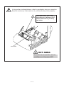
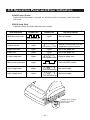
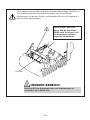
In the position indicated below, a label is provided to alert your attention.
Read the cautionary information on it, and handle the printer properly.
This label alerts you to the
print head as it becames HOT,
and if you touch it, you may
get burnt.
Print head
HOT AREA:
Be careful not to touch this area to
avoid burns as it becomes HOT.
—x—
i
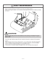
DAILY MAINTENANCE
• Prior to start maintenance work, be sure to turn off the printer.
• When cleaning the platen, use a cotton swab applied with ethyl alcohol and wipe
off stains.
Platen
CAUTION:
Avoid cleaning the print head immediately after printing is finished. The print
head is HOT.
• Use a dry soft cloth to wipe off stains and dust from the surfaces of the printer
covers.
• When wiping clean heavily stained areas, use a cloth which should be dipped in
water and then wrung strongly. Never use organic solvents, such as alcohol,
thinner, trichlene, benzene, ketone, or chemical dusters.
• If the printer is contaminated with paper dust, use a soft brush to wipe off.
— xi —
i
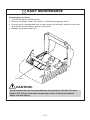
DAILY MAINTENANCE
Cleaning the print head
1 Turn off the power of the printer.
2 Remove the platen roller unit. Refer to “4.6 Removing paper Jams”.
3 Using a gauze impregnated with a small amount of alcohol, wipe off stains and
dust on the heat-emitting surface of the head.
4 Replace the platen roller unit.
Print head
CAUTION:
Avoid cleaning the print head immediately after printing is finished. The print
head is HOT. Do not touch the heat-emitting surface of the head with bare
hands or metal objects.
— xii —
THE TABLE OF CONTENTS
1. GENERAL OUTLINE ................................................................... 1
1.1 Features ..................................................................................................... 1
1.2 Unpacking .................................................................................................. 2
1.3 Before using the printer ............................................................................ 3
2. BASIC SPECIFICATIONS ............................................................ 4
2.1 Model Classification .................................................................................. 4
2.2 Basic Specifications .................................................................................. 5
2.3 Print Paper Specifications ........................................................................ 6
2.3.1 Recommended Paper ....................................................................... 6
2.3.2 Print Position and Barcode Printing ................................................ 7
2.3.3 Cutter Position ................................................................................... 8
3. OUTER APPEARANCE AND COMPONENT PARTS .................. 9
3.1 iDP3240 ...................................................................................................... 9
4. OPERATION .............................................................................. 10
4.1 Connecting the AC Adapter and AC Power Cord ................................. 10
4.2 Connecting Interface Cables .................................................................. 11
4.3 Connecting the Drawer Kick-Out Connector ......................................... 12
4.4 Setting / Replacing Paper Rolls .............................................................. 13
4.4.1 Setting Paper Rolls .......................................................................... 13
4.4.2 Setting Paper Rolls when Easy Loading is Disabled .................... 16
4.5 Removing the Remainder of Paper Rolls .............................................. 17
4.6 Removing Paper Jams ............................................................................ 18
4.7 Releasing a Locked Cutter ...................................................................... 19
4.8 Cleaning the Print Head .......................................................................... 20
4.9 Operation Panel and Error Indication .................................................... 21
4.10 Self Printing ........................................................................................... 23
4.11 Hexadecimal Dump ............................................................................... 24
5. SETTING DIP SWITCHES ......................................................... 25
5.1 Location of DIP Switches ........................................................................ 25
5.2 Table for Setting DIP Switches ............................................................... 26
— xiii —
6. PARALLEL INTERFACE ............................................................. 29
6.1 Bidirectional Parallel Interface (IEEE1284) ............................................ 29
6.1.1 Compatibility Mode (Host → Printer communication :
Centronics compliant) .................................................................... 29
6.1.2 Reverse Mode (Printer → Host communication) .......................... 29
6.1.3 Connector Pin Configuration .......................................................... 30
6.2 Description of Input and Output Signals ............................................... 31
6.2.1 Input and Output Signals ............................................................... 31
6.2.2 Electrical Characteristics ................................................................. 32
6.2.3 Timing Chart (Compatibility Mode) .............................................. 33
6.2.4 Data Reception Control ................................................................... 33
6.2.5 Buffering .......................................................................................... 33
7. SERIAL INTERFACE .................................................................. 34
7.1 Specifications .......................................................................................... 34
7.2 Connector Pin Configuration .................................................................. 35
7.3 Description of Input and Output Signals ............................................... 36
7.3.1 Input and Output Signals ............................................................... 36
7.3.2 Error Detection ................................................................................ 37
7.3.3 Data Reception Control ................................................................... 37
7.3.4 Buffering .......................................................................................... 37
7.3.5 Electrical Characteristics ................................................................. 38
8. DRAWER KICK-OUT CONNECTOR AND POWER CONNECTOR ... 39
8.1 Specifications of Drawer Kick-Out Connector ...................................... 39
8.1.1 Drawer Kick-Out drive signal ......................................................... 39
8.1.2 Electrical characteristics ................................................................. 39
8.1.3 Connector Pin Configuration .......................................................... 39
8.1.4 Drive Circuit ..................................................................................... 40
8.2 Specifications of the Power Connector ................................................. 40
9. MAINTENANCE AND SERVICE ............................................... 41
— xiv —
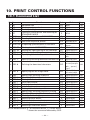
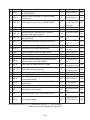
10. PRINT CONTROL FUNCTIONS .............................................. 42
10.1 Command List ....................................................................................... 42
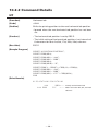
10.2 Command Details .................................................................................. 45
10.2.1 Description of Each Item .............................................................. 45
10.2.2 Command Details .......................................................................... 46
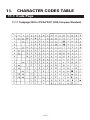
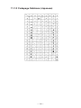
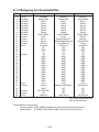
11. CHARACTER CODES TABLE ................................................ 141
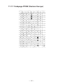
11.1 Code page ............................................................................................ 141
11.1.1 Codepage 00H to 7FH & PC437 (USA, European Standard) ........ 141
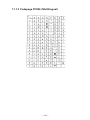
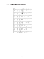
11.1.2 Codepage Katakana (Japanese) ................................................. 142
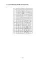
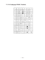
11.1.3 Codepage PC850 (Multilingual) ................................................. 143
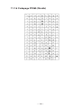
11.1.4 Codepage PC860 (Portuguese) .................................................. 144
11.1.5 Codepage PC863 (Canadian-French) ......................................... 145
11.1.6 Codepage PC865 (Nordic) .......................................................... 146
11.1.7 Codepage PC852 (Eastern Europe) ............................................ 147
11.1.8 Codepage PC866 (Russian) ........................................................ 148
11.1.9 Codepage PC857 (Turkish) ......................................................... 149
11.1.10 Windows Codepage .................................................................. 150
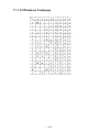
11.2 International Character Codes Table ................................................. 151
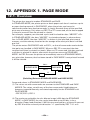
12. APPENDIX 1. PAGE MODE .................................................. 152
12.1 Overview .............................................................................................. 152
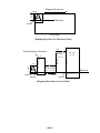
12.2 Mapping of print data in the print area ............................................. 153
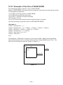
12.2.1 Example of the Use of PAGE MODE .......................................... 155
13. APPENDIX 2. BIDIRECTIONAL PARALLEL INTERFACE ........ 158
13.1 Overview .............................................................................................. 158
13.1.1 Parallel Interface Communication Modes ................................. 158
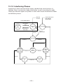
13.1.2 Interfacing Phases ....................................................................... 159
13.2 Negotiation .......................................................................................... 160
13.2.1 Overview ...................................................................................... 160
13.2.2 Negotiation Procedure ................................................................ 160
13.2.3 Precautions .................................................................................. 161
13.2.4 Data Communication from Printer to Host ............................... 162
13.2.4.1 Nibble Mode ........................................................................ 162
13.2.4.2 Byte Mode ............................................................................ 163
13.2.5 Device ID ...................................................................................... 164
13.2.6 Termination .................................................................................. 164
— xv —
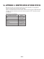
14. APPENDIX 3. IDENTIFICATION OF SEND STATUS ............... 166
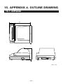
15. APPENDIX 4. OUTLINE DRAWING...................................... 167
15.1 iDP3240 ................................................................................................ 167
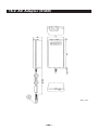
15.2 AC Adapter (31AD) .............................................................................. 168
16. APPENDIX 5. BLOCK DIAGRAM .......................................... 169
— xvi —
<<< German >>>
INHALT
4. BETRIEB .................................................................................. 179
4.1 Anschließen des Netzteils und Netzkabels ......................................... 179
4.2 Anschließen der Schnittstellenkabel ................................................... 180
4.3 Anschließen des Drawer Kickout-Steckers ......................................... 181
4.4 Einlegen / Auswechseln von Papierrollen ........................................... 182
4.4.1 Einlegen von Papierrollen ............................................................ 182
4.4.2 Einlegen von Papierrollen bei deaktiviertem
einfachen Ladevorgang ................................................................ 185
4.5 Entfernen von Papierrollenresten ........................................................ 186
4.6 Beseitigen von Papierstaus .................................................................. 187
4.7 Freigeben eines verriegelten Papierschneiders ................................. 188
4.8 Reinigen des Druckkopfes .................................................................... 189
4.9 Bedienungsfeld und Fehleranzeige ..................................................... 190
4.10 Drucktest .............................................................................................. 192
4.11 Hexdump ............................................................................................. 193
5. EINSTELLEN DER DIP-SCHALTER ......................................... 194
5.1 Position der DIP-Schalter ...................................................................... 194
5.2 DIP-Schaltertabelle ................................................................................ 195
6. PARALLELE SCHNITTSTELLE ................................................ 198
6.1 Bidirektionale parallele Schnittstelle (IEEE1284) ................................ 198
6.1.1 Kompatibilitätsmodus (Host → Druckerkommunikation:
Centronics-kompatibel) ................................................................ 198
6.1.2 Reverse-Modus (Drucker → Hostkommunikation) ..................... 198
6.1.3 Belegung der Anschlußstifte ........................................................ 199
6.2 Beschreibung von Eingangs- und Ausgangssignalen ....................... 200
6.2.1 Eingangs- und Ausgangssignale ................................................. 200
6.2.2 Elektrische Kenndaten .................................................................. 201
6.2.3 Timing-Tabelle (KompatibilitätsModus) ...................................... 202
6.2.4 Datenempfangssteuerung ............................................................ 202
6.2.5 Datenpufferspeicher ..................................................................... 202
— xvii —
7. SERIELLE SCHNITTSTELLE ................................................... 203
7.1 Technische Daten .................................................................................. 203
7.2 Belegung der Anschlußstifte ................................................................ 204
7.3 Beschreibung der Eingangs- und Ausgangssignale .......................... 205
7.3.1 Eingangs- und Ausgangssignale ................................................. 205
7.3.2 Fehlererkennung ........................................................................... 206
7.3.3 Datenempfangssteuerung ............................................................ 206
7.3.4 Pufferung ....................................................................................... 206
7.3.5 Elektrische Kenndaten .................................................................. 207
8. DRAWER KICKOUT- ANSCHLUSS UND STROMANSCHLUSS ..... 208
8.1 Technische Daten des Drawer KickOut-Anschlusses ......................... 208
8.1.1 Drawer KickOut-Treibersignal ...................................................... 208
8.1.2 Elektrische Kenndaten .................................................................. 208
8.1.3 Belegung der Anschlußstifte ........................................................ 208
8.1.4 Treiberschaltung ........................................................................... 209
8.2 Technische Daten des Stromanschlusses ........................................... 209
9. WARTUNG UND KUNDENDIENST ....................................... 210
Note:
Citizen,Citizen logo are registered trademark of Citizen Watch Co.,Ltd.
Windows codepage is a registered trademark of Microsoft Corporation.
— xviii —
1. GENERAL OUTLINE
The iDP3240 is a compact-sized, line thermal printer developed for a variety of
applications. It has abundant built-in features, and can be used as a data
communication terminal, pos terminal, kitchen terminal and for other applications.
1.1 Features
• Compactness and lightweight with a small footprint.
• Low-cost design accomplished by using as small a component count as possible.
• Simple paper setting - All you have to do is just drop in a paper roll and closing
the cover.
• Removable platen structure, which makes paper handling, head cleaning, and
maintenance easy.
• Line thermal printing, which allows high-speed, low-noise operation.
• Registration of user-defined characters and logos into flash memory.
• Built-in input buffer.
• Bar-code printing (Possible using special commands).
• Built-in Drawer Kick-Out interface.
• Auto cutter mechanism provided as a standard unit.
—1—
1.2 Unpacking
When unpacking the printer, confirm that the following are provided:
• Printer ............................................................................................ 1 unit
• Sample paper roll ......................................................................... 1 piece
• AC adapter ..................................................................................... 1 piece
• AC power cord .............................................................................. 1 piece
• User’s manual (This book) ........................................................... 1 piece
Sample
paper roll
Printer
AC adapter
User’s manual
—2—
AC power code
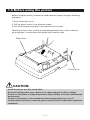
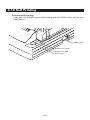
1.3 Before using the printer
Before using the printer, remove the head protective paper using the following
procedure:
1 Open the printer cover.
2 Pull the platen levers in the direction shown.
3 Pull out the protective paper in the direction of the arrow.
When the printer is not used for a prolonged period of time, insert a sheet of
printing paper in use between the platen roller and the head.
Platen lever
Printer cover
CAUTION:
• Install the printer on a flat, sturdy table.
• Do not install the printer near a heater or in a place exposed to direct sunlight.
• Do not use the printer in a high-temperature, high-humidity, or heavily contaminated
environment.
• Do not use the printer in an environment where condensation may occur. If
condensation should occur, leave the power turned off until condensation evaporates
completely.
—3—
2. BASIC SPECIFICATIONS
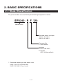
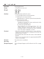
2.1 Model Classification
The printer models are classified by the following designation method:
iDP3240 - R F 120
Model Name
Attached power cord spec
120: For AC 120 V
230: For AC 230 V
Character Set
F: International
Interface
R: Serial (RS-232C)
P: Parallel
(IEEE 1284 compliant)
* Dedicated adapter type and power cord:
31AD-U (AC 120 V 3-wire cord)
31AD-E (AC 230 V Class I cord)
—4—
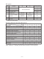
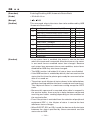
2.2 Basic Specifications
Model
iDP3240-RF120
iDP3240-RF230
iDP3240-PF120
iDP3240-PF230
Line thermal dot print method
104 mm/832 dots
8 dots/mm (203 dpi)
80 mm/sec (Fastest, printing ASCII, print density level 2, applicable to
printing of 60 or fewer columns)
Number of print
Font A: 69/60 columns (12 × 24)
columns*1
Font B: 92/80 columns (9 × 24)
Character size
Font A: 1.25 × 3.00 mm; Font B: 0.88 × 3.00 mm
Character type
Alphanumeric characters, International characters, Codepages PC437,
Katakana, PC850, PC860, PC863, PC865, PC852, PC866, PC857, and Windows
codepage
Logo registration/print Capable of registering user-defined characters and logos into flash memory.
NV bit map data area 256K bytes
Types of bar code
UPC-A/E, JAN (EAN) 13/8 columns, ITF
CODE 39, CODE 128, CODABAR, CODE 93
Line spacing
4.23 mm (1/6 inches); selectable using commands.
Paper
Thermal paper roll: 112 mm +0/–1 × φ 83 mm (See “2.3 Print Paper
Specifications”.)
Interfacing
Serial (RS-232C), Parallel (IEEE1284 compliant, Bi-directional communication)
Input buffer
64K bytes (4K bytes selectable with a DIP switch)
Supply voltage
DC 24 V ±7%
Power consumption
Approx. 100 W
AC adapter spec.
Rated input: AC 120 to 240 V, 50/60 Hz, 120 VA
Rated output: DC 24 V, 1.9 A
Type
31AD-U
31AD-E
Weight
Main body: Approx. 1.3 kg; AC adapter: Approx. 0.45 kg
Outside dimensions
186 (W) × 201 (D) × 123 (H) mm
Operating temperature 5 to 40°C; 35 to 85% RH (No condensation)
and humidity
Storage temperature
–20 to 60°C; 10 to 90% RH (No condensation)
and humidity
Reliability
Print head life: Pulse resistance 1 × 10⁸ pulses (Print ratio 12.5%)
Wear resistance 100 Km (At normal temperature/humidity
with recommended paper used)
Auto cutter life: 500,000 times of cutting (At normal temperature/humidity
with recommended paper used)
Safety Standard*2
UL, C-UL, FCC Class A
TUV, GS, CE marking
Item
Print method
Print width
Dot density
Print speed
*1 The number of print columns can be selected with the DIP switch.
*2 Represents the safety standards acquired when CBM-made adapters (31AD
series) are used.
—5—
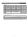
2.3 Print Paper Specifications
2.3.1 Recommended Paper
•
•
•
•
•
•
Type:
Heat sensitive paper
Paper width:
112 + 0/– 1 mm
Paper thickness:
65 ± 5 µm
Roll diameter:
φ 83 mm or less
Print side:
Outer side of the roll (Top surface)
Recommended paper: F220VP/ HP220A (From Mitsubishi Paper)
TF50KS-E2C (From Nippon Paper)
KF50-HDA (From Oji Paper)
or equivalent types of paper
• Core size:
φ12 mm (Inside diameter); φ18 mm (Outside diameter)
CAUTION:
• Use of paper other than the specified papers may cause a difference in print density
from the CBM specifications. In that case, you can select an appropriate print density
with a DIP switch. (See “5. SETTING DIP SWITCHES”)
• Do not stick the end of paper to the core with adhesive paste.
• Avoid allowing the surface of paper to contact with chemicals or oils; otherwise, it
may get colored or the printed data on it may become erased.
• Avoid scraping on the surface of paper with your nail or a metal object; otherwise,
the surface of heat-sensitive paper may get colored.
• Heat-sensitive paper starts getting colored at approx. 70°C; so, be careful not to
expose the paper to the effects from heat, humidity, or sunlight.
—6—
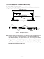
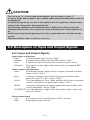
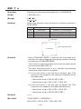
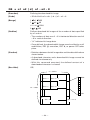
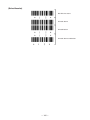
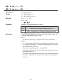
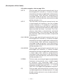
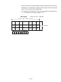
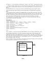
2.3.2 Print Position and Barcode Printing
Roll paper width 112 mm provided:
Paper width 112 mm applies to printing area 103.5 mm (832 dots), and both left
and right margins each ca. 4.25 mm.
Paper width 112 mm
0.125 mm
Print area 103.5 (90) mm
The values in ( )
are for when the
60 column format
is used.
4.25 (11) mm
Figure 1
4.25 (11) mm
Printing Area 1
field 1
1
field 3
192
449
193
448
704
705
field 2
832
Slight shift
possible.
field 4
Figure 2 misaligned printing
Note: Between the left and right margins, four dot fields of the heating element are
available: Dot field 1 is comprised of dots 1 - 192, dot field 2 of dots 193 448, dot field 3 of 449 - 704, and dot field 4 of 705 - 832. The printing position
of each dot field is slightly shifted relative to its adjacent dot fields, as shown
in Figure 2. This means that if a ladder bar code is printed over two adjacent
dot fields, it would appear “stepped” up or down in the middle, possibly
affecting the reading of the bar code adversely. So, be sure to avoid printing
bar codes over two adjacent dot fields.
—7—
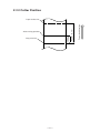
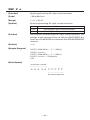
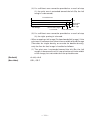
2.3.3 Cutter Position
Top print line
—8—
Paper feed direction
Approx.
15.5 mm
Auto cutting position
Approx. 42 mm
Paper outlet slot
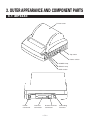
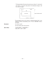
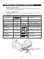
3. OUTER APPEARANCE AND COMPONENT PARTS
3.1 iDP3240
Printer cover
Top cover
Power switch
POWER lamp
ERROR lamp
FEED switch
Power
Connector
Interface
Connector
Drawer Kick-Out
Connector
—9—
Grounding
Terminal
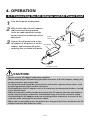
4. OPERATION
4.1 Connecting the AC Adapter and AC Power Cord
1
2
3
Turn off the power of the printer.
With the flat side of the AC adapter’s
cable connector facing upward,
insert the cable connector into the
power connector on the back side of
the printer.
Cable
connector
Connect the AC power cord to the
AC adapter of the printer or the AC AC adapter
adapter, and insert the AC powercord plug into a suitable wall outlet.
Flat side
Power
connector
AC power cord
CAUTION:
• Do not use any AC adapter other than specified.
• When connecting or disconnecting the cable connector of the AC adapter, always pull
on the connector, not on the cable.
• The AC power cord should be connected to a wall outlet separated from others used
by other equipment which tend to emit noise.
• Avoid pulling on the AC adapter cord, or the cord may be damaged or broken, causing
a fire, electric shock.
• When the thunder rumbles nearby, disconnect the AC adapter from the wall outlet to
avoid using the printer; otherwise, a thunderbolt may cause a fire or electric shock.
• Avoid placing the AC adapter cord near a heating device; otherwise, the cover of the
cord may melt, causing a fire or electric shock.
• When you are not going to use the printer for a long period of time, disconnect the AC
adapter from the wall outlet for safety.
— 10 —
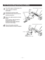
4.2 Connecting Interface Cables
1
Turn off the power of the printer. (As
well as the host computer
connected.)
2
Orienting the interface cable
terminal correctly, insert it into the
interface connector.
3
Secure the cable terminal as shown
below.
Serial interface cable: Fasten the
connector with screws.
Parallel interface cable: Hold the
connector with clamps.
4
Connect the other end of the
interface cable to the host computer.
Serial interface connector
Serial interface
cable
Parallel interface connector
Clamps
Parallel interface cable
— 11 —
4.3 Connecting the Drawer Kick-Out Connector
1
2
Turn off the power of the printer.
3
Fasten the ground wire to the
ground connector on the printer
with a screw.
Drawer kick-out connector
Orienting the Drawer Kick-Out Cable
Connector correctly, insert it into the
Drawer Kick-Out Connector on the
back of the printer.
Ground wire
Drawer Kick-Out Cable connector
CAUTION:
• Do not connect any other device than the specified drawer (Solenoid) to the Drawer
Kick-Out Connector. (Do not connect a telephone line either.)
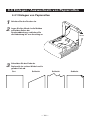
— 12 —
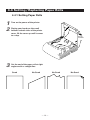
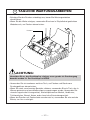
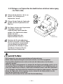
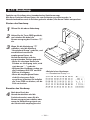
4.4 Setting / Replacing Paper Rolls
4.4.1 Setting Paper Rolls
1
2
3
Turn on the power of the printer.
Placing your hands on the small
hollows on both sides of the printer
cover, lift the cover up until it comes
to a stop.
Small
hollows
Cut the end of the paper roll at right
angles and in a straight line.
Good
No Good
No Good
— 13 —
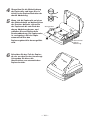
No Good
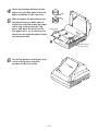
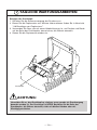
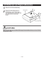
4
Check the winding direction of the
paper roll, and then place it into the
paper roll holder in the Top cover.
5
With the paper roll placed between
the platen levers on both sides of
the printer, pull the end of the paper
roll out up to the end of the Top
cover, and close the printer cover.
The paper roll is set to come out of
the printer through the paper output
slot automatically.
Platen lever
Platen lever
Top cover
6
Cut off the portion of the paper that
is out of the printer using the
tear bar on the auto cutter.
— 14 —
CAUTION:
• Always use the specified types of paper roll.
• Use of other types of paper roll may not be able to guarantee the specified print
quality or service life of the printer.
• Pull out the end of the paper roll up to the end of the upper cover.
The end of the paper should not go beyond or short of the end of the Top cover.
• When the paper roll is set, the paper end may sometimes come out folded over.
• If the paper roll is set inclined, pull the platen levers to adjust the position of the paper
roll.
• During printing, do not open the printer cover.
• If the paper fails to come out of the paper output slot, check to make sure the paper
end is properly cut, and then reset the paper roll. Also, after the printer has been used
for prolonged periods of time, the platen roller may have been covered with paper
debris, which may prevent the paper from coming out. If this happens, use a soft cloth
dabbed with ethyl alcohol to wipe the paper debris off the surface of the platen roller.
• When the paper fails to come out of the paper output slot, you can set the paper roll
using the procedure below:
1. While having the end of the paper roll inserted straight between the platen roller
and the head, press the FEED switch. The paper is pulled in by the platen roller and
guided into the auto cutter. (The of end of the paper will slightly stick out of the
paper output slot of the cutter.)
2. After closing the printer cover, the paper will be fed for a few more lines and then
automatically cut. Now, the printer is ready for printing. Remove the piece of paper
cut off.
— 15 —
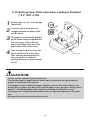
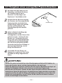
4.4.2 Setting Paper Rolls when Easy Loading is Disabled
(“5.2” DS1-3 ON)
1
2
Follow steps 1 to 4 in “4.4.1 Setting
Paper Rolls”.
3
The paper is automatically pulled in
by the platen roller and guided into
the auto-cutter. (The end of the
paper will slightly stick out of the
paper output slot of the cutter.)
4
After closing the printer cover, the
paper will be fed for a few more
lines and then automatically cut.
Now, the printer is ready for
printing. Remove the piece of paper
cut off.
Insert the end of the paper roll
straight between the platen roller
and the head.
Top cover
CAUTION:
• Always use the specified types of paper roll.
• Use of other types of paper roll may not be able to guarantee the specified print
quality or service life of the printer.
• If the paper is slack, roll back the paper slightly to remove the slack. If there is too
much slack, the paper may be too far from the paper sensor, possibly causing items 3
and 4 in “4.4.2 Setting Paper Rolls when Easy Loading is Disabled” to occur.
• If the paper roll is inclined, pull the platen levers to adjust the position of the paper
roll.
• During printing, do not open the printer cover.
— 16 —
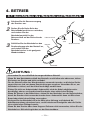
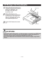
4.5 Removing the Remainder of Paper Rolls
1
2
Open the printer cover.
Platen lever
Pull both platen levers in the
direction of the arrows to separate
the platen roller from the head, and
then pull out the paper roll.
Printer cover
CAUTION:
When removing the paper roll (in either direction), the platen levers must be pulled.
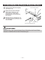
— 17 —
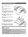
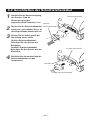
4.6 Removing Paper Jams
1
2
3
4
Turn off the power of the printer.
5
Hold and lift the platen levers, and
the platen roller unit can be
removed.
Chassis hook
Open the printer cover.
Cut the paper near the paper
insertion slot.
Move the head springs on both sides
in the direction of arrows to unhook
them from the chassis hooks, and lift
them up.
Push guide
Head spring
Platen roller unit
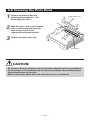
6
Remove any paper remaining in the
paper path.
7
Holding the platen roller unit in the
correct orientation, install it into the
printer with its bushes fitted in the
bush guides on the chassis.
8
While pushing on the platen roller
unit lightly, lower the head springs
to hook them to the chassis hooks.
Push guide
CAUTION:
• Do not attempt to do anything inside the printer immediately after printing because
the head and motor are very hot.
• Do not force the head springs to move beyond their moving range.
• When removing remaining paper, do not touch the heated surface of the head with
bare hand or with metal.
• After inserting the platen roller, be sure to confirm that it has been set correctly.
• When removing the platen roller unit, the power must be turned off.
— 18 —
4.7 Releasing a Locked Cutter
1
Remove any paper in the paper path
following the procedure in “4.6
Removing Paper Jams”.
2
Turn on the power of printer. The
auto cutter initializes itself, returning
the cutter blade to the normal
position. The alarm condition is also
cleared.
3
If Step 2 failed to return the cutter
blade and clear the alarm, then turn
the printer off and using a pair of
tweezers or a screwdriver, rotate the
emergency knob located in a hole at
the bottom of the printer in the
direction shown to return the cutter
blade.
4
Use a pair of tweezers to remove
any remaining paper around the
cutter blade.
Emergency knob
CAUTION:
• Do not attempt to do anything inside the printer immediately after printing because
the head and motor are very hot.
• When removing remaining paper, do not touch the heated surface of the head with
bare hand or with metal.
• By using the DIP switch, you can either engage or disengage the cutter. When using
the printer with the cutter disengaged, make sure that the cutter blade has been
completely returned. If it has not, follow the above procedure to return it.
— 19 —
4.8 Cleaning the Print Head
1
Remove the platen roller unit
following the procedure in “4.6
Removing Paper Jams”.
2
Wipe off stains, such as dust and the
like, on the heating element of the
head using a cotton swab
impregnated with ethyl alcohol.
3
Replace the platen roller unit.
Platen roller unit
Print head
CAUTION:
• Do not touch the heat-emitting surface of the head with bare hands or metal objects.
• Do not attempt to do anything inside the printer immediately after printing because
the head and motor are very hot.
• When removing the platen roller unit, the power must be switched off.
— 20 —
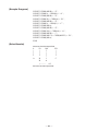
4.9 Operation Panel and Error Indication
POWER lamp (Green)
Lights when the power is turned on. It blinks when a memory check error has
occurred.
ERROR lamp (Red)
Lights or blinks to show different error states.
Error indication
Memory check error
POWER LED
(Quick blinking)
ERROR LED
Recovery method
Lights
Not recoverable
Lights
Close the cover
Cover open
Lights
Head overheat
Lights
Paper Near-end
Lights
Lights
Set a new paper roll
Paper end
Lights
Lights
Set a new paper roll
Cutter motor lock
Lights
Macro execution wait
Lights
Low voltage error
Lights
High voltage error
Lights
(Slow blinking 1.5 second)
(Quick & Slow blinking)
Remove paper jams
Press the FEED switch
(Slow blinking)
(Quick & Slow blinking)
(Quick & Slow blinking)
POWER
ERROR
FEED
— 21 —
Recovers automatically when the
temperature returns to normal
Not recoverable
Not recoverable
POWER lamp (Green)
ERROR lamp (Red)
FEED switch
Description of errors
Cover open:
When you open the printer cover, the cover open sensor is
activated, causing the ERROR LED to light and the printing
operation to stop. However, by making a proper setting on
the DIP switch, the paper can be fed through the printer with
the cover open.
Head overheat:
To protect the print head from being overheated, the head
temperature sensor is activated if the head temperature rises
over approx. 65°C, causing the ERROR LED to blink and the
printing operation to stop. Printing resumes automatically
when the head temperature lowers below approx. 60°C.
Paper Near-end:
When the diameter of the paper roll becomes small, the Paper
Near End sensor located on the side of the upper cover roller
will be activated. An ERROR light will come on to indicate that
the paper supply has become low. (See “Selecting the Paper
Sensor valid for a paper end signal output” and “Selecting
the Paper Near-end Sensor valid for print stop” described in
“10. PRINT CONTROL FUNCTIONS”.)
Paper end:
When the paper roll has run out, the Paper end-Sensor
located near the print head on the paper path detects the end
of the paper roll, causing the ERROR LED to light and printing
to stop. (See “Selecting the Paper Sensor valid for a paper
end signal output” and “Selecting the Paper Near-end Sensor
valid for print stop” described in “10. PRINT CONTROL
FUNCTIONS”.)
Cutter motor lock: While the cutter motor is running, if the cutter position
detecting sensor inside the cutter unit remains ON or OFF for
approx. 1 second or more, the printer determines that the
motor has locked, causing the cutter operation and printing to
stop. (See “4.7 Releasing a Locked Cutter”.)
Low voltage error: Occurs when the voltage supplied to the printer decreases ; if
this has occurred, turn the power off immediately.
High voltage error: Occurs when the voltage supplied to the printer increases ; if
this has occurred, turn the power off immediately.
FEED switch
• Pressing this switch briefly causes one line of paper feeding. Holding down the
switch causes continuous paper feeding.
• While a macro is waiting to be executed, pressing the switch causes the macro
to be executed.
— 22 —
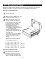
4.10 Self Printing
Performing Self Printing
If you press the POWER switch while holding down the FEED switch, self printing
is performed.
PO
WE
R
ER
RO
R
POWER switch
FEE
D
POWER lamp (Green)
ERROR lamp (Red)
FEED switch
— 23 —
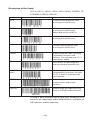
4.11 Hexadecimal Dump
Hexadecimal dump function allows data sent from the host computer to be printed in
hexadecimal numbers as well as in characters corresponding to the numbers.
Starting hexadecimal dump
1
2
3
Open the top cover.
While pressing the FEED switch, turn
on the power of the printer “➀”.
When you close the cover “➁”, a
message “Hexadecimal Dump” is
printed on paper, and then the data
received afterward is printed in
hexadecimal numbers and the
corresponding characters.
• If a character is not available
corresponding to the data received,
“ . ” is printed instead.
• During hexadecimal dump, no
other functions than DLE EOT and
DLE ENQ work.
• If the data received is not enough
for a full line, pressing the FEED
switch causes the line to be
printed.
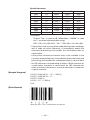
<Example of hexadecimal dump>
=== Hexadecimal Dump ===
Quitting hexadecimal dump
4
After hexadecimal printing, this
function is terminated when you
turn off the power or when a reset
signal is received from the interface.
— 24 —
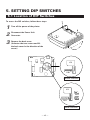
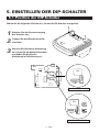
5. SETTING DIP SWITCHES
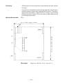
5.1 Location of DIP Switches
To access the DIP switches, follow these steps:
1
2
Turn off the power of the printer.
3
Remove the back cover.
(Unfasten the two screws and lift
the back cover in the direction of the
arrow.)
Disconnect the Power Unit
Connector.
12345678
ON
ON
DS1
12345678
IC2
DS2
Parallel Interface
IC2
ON
12345678
DS2
12 3 4
12345678
12 3 4
ON
DS1
DS3
DS4
Serial Interface
— 25 —
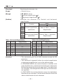
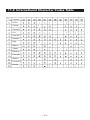
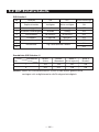
5.2 Table for Setting DIP Switches
DIP switch 1
No.
Function
ON
OFF
Factory setting
1
Auto cutter
Available
Not available
ON
2
Cover open
Invalid
Valid
OFF
3
Easy Loading
Invalid
Valid
OFF
4
Print columns
60 columns
69 columns
OFF
5
CR mode
LF Operation
Ignored
OFF
6
Input buffer
4K bytes
64K bytes
OFF
7
8
Print density
ON
See the table below
OFF
Print density (DIP switch 1)
Print density
No.
Level 1
(Light)
Level 2
(Standard)
Level 3
(Slightly dark)
Level 4
(Dark)
7
OFF
ON
OFF
ON
8
OFF
OFF
ON
ON
Note: If print density is set to level 2 or over, print speed may decrease.
— 26 —
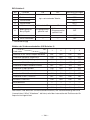
DIP switch 2
No.
Function
1
Character code
2
Character code
3
Character code
4
Character code
5
JIS/Shift JIS
6
Condition for BUSY
to occur
7
8
ON
OFF
Factory setting
OFF *
OFF *
See the table below.
OFF *
OFF *
Shift JIS
JIS
OFF
Reception
buffer full
• Off-line
• Reception
buffer full
OFF
Unused
—
—
OFF
Unused
—
—
OFF
* : Depends on destinations.
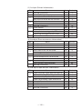
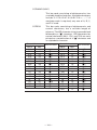
Selection of Character Code tables (DIP switch 2)
No.
Code page
1
2
3
4
Codepage PC437 (USA, European Standard)
OFF
OFF
OFF
OFF
Codepage Katakana (Japanese)
ON
OFF
OFF
OFF
Codepage PC850 (Multilingual)
OFF
ON
OFF
OFF
Codepage PC860 (Portuguese)
ON
ON
OFF
OFF
Codepage PC863 (Canadian-French)
OFF
OFF
ON
OFF
Codepage PC865 (Nordic)
ON
OFF
ON
OFF
Codepage PC852 (Eastern Europe)
OFF
ON
ON
OFF
Codepage PC866 (Russian)
ON
ON
ON
OFF
Codepage PC857 (Turkish)
OFF
OFF
OFF
ON
Windows Codepage
ON
OFF
OFF
ON
Not defined
—
—
—
—
•
Blank page
—
—
—
—
ON
ON
ON
ON
“Blank page”is an area for user registration, and is blank (Space) by default.
When “Katakana” is selected, the international character is set for Japanese.
— 27 —
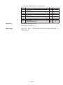
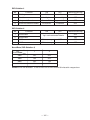
DIP switch 3
No.
Function
1
Bit length
2
Parity
3
Odd /Even
4
Communication mode
ON
OFF
Factory setting
7 bits
8 bits
OFF
Available
Not available
OFF
Even number
Odd number
OFF
XON/XOFF
DTR/DSR
OFF
ON
OFF
Factory setting
DIP switch 4
No.
1
Function
Baud rate
OFF
See the table below.
2
Baud rate
3
DSR
Reset
DSR
OFF
4
INIT
Reset
—
OFF
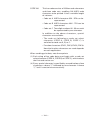
Baud rate (DIP switch 4)
No.
Baud rate
1
2
2400
OFF
OFF
4800
ON
OFF
9600
OFF
ON
19200
ON
ON
Note: Dip switches 3 and 4 are only for serial interface.
— 28 —
ON
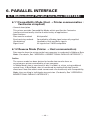
6. PARALLEL INTERFACE
6.1 Bidirectional Parallel Interface (IEEE1284)
6.1.1 Compatibility Mode (Host → Printer communication :
Centronics compliant)
• General description
This printer provides Compatibility Mode, which specifies the Centronics
interface conventionally used for a wide variety of applications.
• Specifications
Data transfer method:
8-bit parallel
Synchronizing method:
Controlled by nStrobe signal externally supplied
Handshaking:
Handled by nAck and Busy signals
Signal level:
All signals are C-MOS compatible
6.1.2 Reverse Mode (Printer → Host communication)
Data transfer from the printer to the host computer is conducted in Nibble or Byte
Mode. (For details, See “APPENDIX 2. BIDIRECTIONAL PARALLEL INTERFACE”.)
Outline
The reverse mode has been devised to handle data transfer from an
asynchronous printer controlled by a host computer.
In Nibble Mode, data is transferred, 4-bits (A nibble) at a time, using traditional
control lines. In Byte Mode, data is transferred by making 8-bit data lines bidirectional. Note that either mode cannot work simultaneously with Compatibility
Mode, thus resulting in half-duplex transmission. (For details, See “APPENDIX 2.
BIDIRECTIONAL PARALLEL INTERFACE”.)
— 29 —
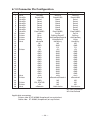
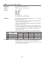
6.1.3 Connector Pin Configuration
Pin
1
2
3
4
5
6
7
8
9
10
11
12
13
14
15
16
17
18
19
20
21
22
23
24
25
26
27
28
29
30
31
32
33
34
35
36
Source
Host
Host/Ptr
Host/Ptr
Host/Ptr
Host/Ptr
Host/Ptr
Host/Ptr
Host/Ptr
Host/Ptr
Printer
Printer
Printer
Printer
Host
Printer
Host
Printer
Printer
Printer
Host
Compatibility Mode
Nibble Mode
Byte Mode
nStrobe
Data0(LSB)
Data1
Data2
Data3
Data4
Data5
Data6
Data7(MSD)
nAck
Busy
PError
Select
nAutoFd
NC
GND
FG
+5V
GND
GND
GND
GND
GND
GND
GND
GND
GND
GND
GND
GND
nInit
nFault
GND
DK_STATUS
+5V
nSelectIn
HostClk
Data0(LSB)
Data1
Data2
Data3
Data4
Data5
Data6
Data7(MSD)
PtrClk
PtrBusy/Data3.7
AckDataReq/Data2.6
Xflag/Data1.5
HostBusy
ND
GND
FG
+5V
GND
GND
GND
GND
GND
GND
GND
GND
GND
GND
GND
GND
nInit
nDataAvail/Data0.4
ND
ND
ND
1284-Active
HostClk
Data0(LSB)
Data1
Data2
Data3
Data4
Data5
Data6
Data7(MSD)
PtrClk
PtrBusy
AckDataReq
Xflag
HostBusy
ND
GND
FG
+5V
GND
GND
GND
GND
GND
GND
GND
GND
GND
GND
GND
GND
nInit
nDataAvail
ND
ND
ND
1284-Active
NC: Not Connected
ND: Not Defined
Applicable connectors
Printer side: 57LE-40360 (Amphenol) or equivalent
Cable side: 57-30360 (Amphenol) or equivalent
— 30 —
CAUTION:
• The first letter “n” of each signal name indicates that the signal is active “L”.
• If any one of the above signals is not available, bidirectional communication cannot be
accomplished.
• In interfacing signals, be sure to use twist-paired wires for signal lines, and the return
side must be connected to signal ground level.
• All interfacing conditions are specified based on C-MOS level and must satisfy the
following characteristics. Also, specify the rising and falling time of each signal as 0.5
µs.
• Avoid transferring data by ignoring nAck or Busy signal; otherwise, the data may be
erased.
• Make the interface cables as short as necessary.
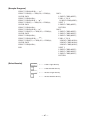
6.2 Description of Input and Output Signals
6.2.1 Input and Output Signals
Input signals to the printer
• Data:
An 8-bit parallel signal. (Active “High”)
• nStrobe:
A strobe signal to help read 8-bit data. (Active “Low”)
• nInit:
A signal to reset the entire printer functions. (Active “Low”)
• nSelectIn:
This signal is made “High” when the printer is changed to IEEE
1284 mode.
Output signals from the printer
• nAck:
An 8-bit data request signal, which is output at the end of a Busy
signal. (Active “Low”)
• Busy:
A signal to indicate a busy state of the printer. Input new data
when this signal is “Low”. (Active “High”)
• nFault:
This signal becomes “Low” when alarmed. At this time, all control
circuits in the printer are deactivated. (Active “Low”)
• PError:
A signal to indicate that the paper supply has become low or has
run out completely. (Active “High”)
• DK_STATUS: This signal becomes “High” when the switch is open, and “Low”
when it is closed.
Power related signal
• +5 V:
A 5 V signal, which is pulled up by a 3.3 KΩ resistor.
• GND:
Common ground on circuits.
— 31 —
6.2.2 Electrical Characteristics
Input signal level (nStrobe, Data 0-7)
All the input signals are at the C-MOS level.
“HIGH” level: 4.0 V minimum
“LOW” level: 0.9 V maximum
Output signal level
All the output signals are at the C-MOS level.
“HIGH” level: 2.4 V minimum
“LOW” level: 0.4 V maximum
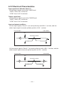
Input and output conditions
All the input signals, Data 0-7, are each pulled up with 50 kΩ resistor, and the
other input signals are each pulled up with a 3.3 kΩ resistor.
[Printer Side]
[Host Side]
Vcc
Twisted Pair Wire
All the output signals, Data 0-7, are each pulled up with a 50 kΩ resistor, and the
other output signals are each pulled up with a 3.3 kΩ resistor.
[Printer Side]
[Host Side]
Vcc
Twisted Pair Wire
— 32 —
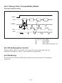
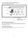
6.2.3 Timing Chart (Compatibility Mode)
Data input and print timing
Power
Data
T2
nStrobe
T1
T3
T6
T4
Busy
nAck
T5
T1, T2, T3:
T4:
T5:
T6:
0.5 µs MIN
270 ns MAX
2.3 µs TYP
500 ms MIN (At power- on)
6.2.4 Data Reception Control
When the Busy signal is at “LOW”, the printer can receive data from the host
computer, but when at “HIGH”, data reception is not possible.
6.2.5 Buffering
Since the printer can buffer 64K bytes of data, the host computer is immediately
made free.
— 33 —
7. SERIAL INTERFACE
7.1 Specifications
(1) Synchronizing system
Asynchronous
(2) Baud rate
2400, 4800, 9600, or 19200 bps (User selectable)
(3) Configuration of one word
Start bit:
Data bits:
Parity bit:
Stop bit:
1-bit
7 or 8-bits (User selectable)
Odd, even, or none (User selectable)
1-bit or more
(4) Signal polarity
RS-232C
• Mark = Logic “1” (–3 V to –12 V)
• Space = Logic “0” (+3 V to +12 V)
(5) Received data (RD signal)
RS-232C
• Mark = 1
• Space = 0
(6) Reception control (DTR signal)
RS-232C
• Mark: Data transfer disabled
• Space: Data transfer enabled
(7) Transmission control (TD signal)
DC1 code (11H)X-ON: Data reception enabled
DC3 code (13H)X-OFF: Data reception disabled
— 34 —
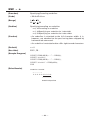
7.2 Connector Pin Configuration
No.
Signal name
Input/output
Function
1
FG
—
Grounding for safety
2
TD
Output
Transferred data
3
RD
Input
Received data
4
RTS
Output
Same as DTR
Input
Data set ready or reset
(Selected with a DIP switch)
6
DSR
7
GND
—
Ground for signals
20
DTR
Output
Printer Busy signal
25
INIT
Input
Reset (Selected with a DIP switch)
Applicable connectors (D-Sub connectors)
Printer side: 17LE-13250 (DDK) or equivalent
Cable side: 17JE-23250 (DDK) or equivalent
CAUTION:
• Signals for RS-232C are specified based on EIA RS-232C.
• While data is not being transferred, always maintain the received data in a mark state.
— 35 —
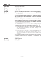
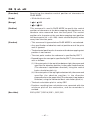
7.3 Description of Input and Output Signals
7.3.1 Input and Output Signals
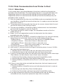
(1) RD
This is a serial reception data signal. When a framing error, overrun error or
parity error occurs, the data containing the error is printed as a “?”.
(2) DTR, RTS
When this signal is Ready, you can write data or commands into the input buffer.
If you do so while the signal is Busy, an overrun error occurs, and the previously
written data will be ignored. Data can be written into the input buffer even during
printing. A Busy signal is also issued at the time of power-on, test printing, online communication, and resetting.
(3) TD
As data is received, the remaining capacity of the printer’s input buffer decreases.
When it becomes less than 128 bytes, a DC3 (13H) (Data reception disable signal)
is output to the host computer. On the other hand, when the remaining capacity
of the input buffer increases to 256 or more bytes, a DC1 (11H)(Data reception
enable signal) is output to the host computer.
(4) DSR
During status information transmission, if DTR/DSR control is selected, the host
computer transfers data to the printer after checking this signal is a space. If DTR/
DSR control is not selected, the host computer ignores this signal and sends data
to the printer. Also, this signal can be used as a reset signal after switching a DIP
switch. (See “5.2 Table for Setting DIP Switches”.) When the pulse width of the
signal is 1 ms or longer, a reset will be applied.
(5) INIT
This signal can be used as a reset signal after switching a DIP switch. (See “5.2
Table for Setting DIP Switches”.) When the pulse width of the signal is 1 ms or
longer in space state, a reset will be applied.
(6) FG
This is a Frame Ground signal.
(7) GND
This is a common ground on circuits.
— 36 —
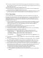
7.3.2 Error Detection
Detection of parity errors, framing errors, and overrun errors is provided with this
printer. When an error is detected, the data containing the error is stored in the
buffer as a “?”.
(1) Framing error
If a space state is detected at the timing of stop bit detection, this indicates that
an error has occurred. The data containing the error is stored in the buffer as a
“?”.
(2) Parity error
With parity check specified, when data is parity-checked and an error is detected,
the data containing the error is stored in the buffer as a “?”.
(3) Overrun error
If an overrun error is detected, the data containing the error is stored in the buffer
as a “?”.
7.3.3 Data Reception Control
With DTR/DSR control selected, when DTR signal becomes “Low”, the printer can
receive data from the host computer, but when it is “High”, the printer cannot
receive data. With DTR/DSR control not selected, after sending out X-ON, the
printer receives data from the host computer, but cannot receive data from the
host computer after X-OFF is sent out.
7.3.4 Buffering
When data is transferred to the input buffer, DTR and TD signals are used as
control signals.
• Refer to 7.3.1 (2) for DTR signal.
• Refer to 7.3.1 (3) for TD signal.
— 37 —
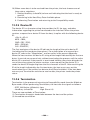
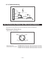
7.3.5 Electrical Characteristics
RS-232C circuit
Input (RD, DSR, INIT)
[Printer Side]
[Host Side]
Equivalent to MAX232
Output (DTR, TD, RTS)
[Printer Side]
[Host Side]
Equivalent to MAX232
— 38 —
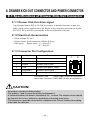
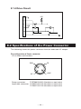
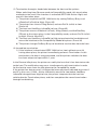
8. DRAWER KICK-OUT CONNECTOR AND POWER CONNECTOR
8.1 Specifications of Drawer Kick-Out Connector
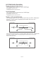
8.1.1 Drawer Kick-Out drive signal
A pulse specified by ESC p, DLE DC4 is output. In parallel interface mode, the
SW(+) state can be confirmed at No. 34 pin of the interface connector or by the
DLE EOT, GS a and GS r commands at the serial/parallel interface.
8.1.2 Electrical characteristics
• Drive voltage: DC 24 V
• Drive current: 0.8 A maximum (Within 510 ms)
• SW signal:
Signal level “L” = 0 to 0.5 V
“H” = 3 to 5 V
8.1.3 Connector Pin Configuration
No.
Signal
Function
1
FG
Frame Ground
2
DRAWER 1
Drawer 1 drive signal
3
DRSW
Drawer switch input
4
VDR
Drawer drive power supply
5
DRAWER 2
Drawer 2 drive signal
6
GND
Common ground on circuits
1
6
Connector used:
TM5RJ3-66 (Hirose) or equivalent
Applicable connector: TM3P-66P (Hirose) or equivalent
CAUTION:
• No output is produced while printing.
• The drawers 1 and 2 cannot be driven simultaneously.
• A solenoid used for the drawer should be of 36 Ω or more. The output current should
be kept at 0.8 A or less; otherwise, breakdown or burning could occur.
• This connector cannot be connected to a telephone line. Do not connect to anything
other than the solenoid.
— 39 —
8.1.4 Drive Circuit
+5V
1
2
3
VDR
4
5
6
8.2 Specifications of the Power Connector
The following shows the power connector from the dedicated AC adapter.
Pin configuration of Power connector
(Pin number and function)
FG
GND
2
3
1
+24V
N.C
Power connector:
TCS7960-53-2010 (Hosiden) or equivalent
Applicable connector: TCP8927-63-1100 (Hosiden) or equivalent
TCP8927-53-1100 (Hosiden) or equivalent
— 40 —
9. MAINTENANCE AND SERVICE
For the information on maintenance and service, please contact your CBM dealer
or at the following addresses:
Northern America
CBM America Corporation
Service Center
365 Van Ness Way
Suite 510
Torrance, CA 90501, U.S.A
Other Areas
Japan CBM Corporation
Information Systems Division
CBM Bldg., 5-68-10, Nakano
Nakano-ku, Tokyo 164-0001
Japan
TEL +1-310-781-1460
FAX +1-310-781-9157
TEL +81-3-5345-7540
FAX +81-3-5345-7541
— 41 —
10. PRINT CONTROL FUNCTIONS
10.1 Command List
No.
1
2
3
4
5
6
7
Command
Function
HT
Horizontal tab
LF
Printing and paper feed
CR
Back to printing
Printing in PAGE MODE and returning to
FF
STANDARD MODE
CAN
Canceling print data in PAGE MODE
DLE EOT Sending status in real-time
DLE ENQ Real-time request to printer
Mode
Code
S.P. <09>H
S.P. <0A>H
S.P. <0D>H
P
<0C>H
P
<18>H
S.P. <10>H<04>H<n>
S.P. <10>H<05>H<n>
<10>H<14>H<n>
8 DLE DC4 Outputting specified pulse in real-time
S.P.
<m><t>
9 ESC FF
Printing data in PAGE MODE
P
<1B>H<0C>H
10 ESC SP Setting the right spacing of the character S.P.* <1B>H<20>H<n>
11 ESC !
Collectively specifying the printing mode
S.P. <1B>H<21>H<n>
12 ESC $
Specifying the absolute positions
S.P.* <1B>H<24>H<n1>
<n2>
13 ESC %
Specifying/Canceling download character set S.P. <1B>H<25>H<n>
<1B>H<26>H<s>H
<n><m>[<a><p1>
14 ESC &
Defining the download characters
S.P.
<p2> ⋅ ⋅ <ps×a>]
m-n+1
<1B>H<2A>H<m>
15 ESC
Specifying the bit image mode
S.P.
<n1><n2>[<d>]k
16 ESC Specifying/Canceling underline
S.P. <1B>H<2D>H<n>
17 ESC 2
Specifying 1/6-inch line feed rate
S.P. <1B>H<32>H
18 ESC 3
Setting line feed width
S.P.* <1B>H<33>H<n>
19 ESC =
Data input control
S.P. <1B>H<3D>H<n>
20 ESC ?
Deleting download characters
S.P. <1B>H<3F>H<n>
21 ESC @
Initializing the printer
S.P. <1B>H<40>H
22 ESC D
Setting horizontal tab position
S.P. <1B>H<44>H [<n>]k<00>
23 ESC E
Specifying/Canceling Emphasis Printing
S.P. <1B>H<45>H<n>
24 ESC G
Specifying/Canceling Double strike printing S.P. <1B>H<47>H<n>
25 ESC J
Printing and feeding paper
S.P.* <1B>H<4A>H<n>
26 ESC L
Selecting PAGE MODE
S <1B>H<4C>H
27 ESC M
Selection of character fonts
S.P. <1B>H<4D>H<n>
28 ESC R
Selecting the international character set
S.P. <1B>H<52>H<n>
<1B>H<53>H
29 ESC S
Selecting STANDARD MODE
P
*
In the Mode column: S = STANDARD MODE, P = PAGE MODE
* shows the command affected by GS P.
— 42 —
Page
46
47
48
49
50
51
54
55
56
57
59
61
63
64
66
68
69
70
71
72
73
74
75
76
77
78
79
80
81
No. Command
30 ESC T
31 ESC V
Function
Selecting the character printing direction
in PAGE MODE
Specifying/Canceling 90°-right-turned
characters
Mode
<1B>H<54>H<n>
82
S
<1B>H<56>H<n>
83
P*
Defining the print area in PAGE MODE
33 ESC \
34 ESC a
Specifying the relative position
S.P.*
Aligning the characters
S.P.
Selecting the Paper Sensor valid for
S.P.
a paper end signal output
Selecting the Paper Near-end Sensor valid
S.P.
for print stop
36 ESC c4
37 ESC c5
Enabling/Disabling the panel switches
S.P.
38 ESC d
Printing and feeding the paper by “n” lines
S.P.
39 ESC p
Generating the specified pulses
S.P.
40 ESC t
41 ESC {
42 GS !
Selecting the character code table
S.P.
Specifying/Canceling the inverted characters S
Specifying the character size
S.P.
Specifying the absolute vertical position
P*
of characters in PAGE MODE
43 GS $
44 GS
*
Defining the download bit image
45 GS ( A
Execution of test printing
46 GS /
47 GS :
50 GS I
Printing the downloaded bit image
Starting/Ending macro definition
Specifying/Canceling the black/white
inverted printing
Selecting of printing position of HRI
characters
Sending the printer ID
51 GS L
Setting the left margin
52 GS P
Specifying the basic calculation pitch
53 GS V
Cutting the paper
48 GS B
49 GS H
S.P.
S
S.P.
S.P.
<1B>H<57>H<xL><xH>
<yL><yH><dxL><dxH>
<dyL><dyH>
<1B>H<5C>H<nL><nH>
<1B>H<61>H<n>
<1B>H<63>H<33>H
<n>
<1B>H<63>H<34>H
<n>
<1B>H<63>H<35>H
<n>
<1B>H<64>H<n>
<1B>H<70>H<m>
<n1><n2>
<1B>H<74>H<n>
<1B>H<7B>H<n>
<1D>H<21>H<n>
<1D>H<24>H<nL>
<nH>
<1D>H<2A>H<n1>
<n2>[<d>]n1×n2×8
<1D>H<28>H<41>H
<pL><pH><n><m>
<1D>H<2F>H<m>
<1D>H<3A>H
84
86
87
88
89
90
91
92
93
94
95
97
98
100
101
102
S.P. <1D>H<42>H<n>
103
S.P. <1D>H<48>H<n>
104
S.P. <1D>H<49>H<n>
<1D>H<4C>H<nL>
S*
<nH>
<1D>H<50>H<x>
S.P.
<y>
(1)<1D>H<56>H<m>
S.P.* (2)<1D>H<56>H<m>
<n>
106
In the Mode column: S = STANDARD MODE, P = PAGE MODE
* shows the command affected by GS P.
— 43 —
Page
P
32 ESC W
35 ESC c3
Code
107
108
109
No. Command
Function
54 GS W
Setting the print area width
55 GS \
Specifying the relative vertical position
of a character in PAGE MODE
56 GS ^
Executing the macro
58 GS f
59 GS h
Enabling/Disabling ASB (Automatic Status
Back)
Selecting the font of HRI characters
Specifying the height of the bar code
60 GS k
Printing the bar code
61 GS r
Sending status
62 GS v0
Printing of raster bit image
63 GS w
Specifying the horizontal size
(Magnification) of bar code
57 GS a
Mode
Code
<1D>H<57>H<nL>
S.P.*
<nH>
<1D>H<5C>H<nL>
S.P.*
<nH>
<1D>H<5E>H<n1>
S.P.
<n2><n3>
Page
S.P. <1D>H<61>H<n>
114
S.P. <1D>H<66>H<n>
S.P. <1D>H<68>H<n>
(1)<1D>H<6B>H<m>
[d1...dk]NUL
S.P.
(2)<1D>H<6B>H<m>
<n>[d1...dn]
S.P. <1D>H<72>H<n>
<1D>H<76>H<30>H
S <m><xL><xH>
<yL><yH>[<d>]k
117
118
S.P. <1D>H<77>H<n>
131
110
112
113
119
127
129
Command relative to NV memory
No. Command
Function
64 FS g1
Writing data into the download user NV memory
65 FS g2
Reading data from the download user NV memory
66 FS p
Printing the download NV bit images
67 FS q
Defining the download NV bit image
Mode
Code
<1C>H<67>H<31>
<m>H<a1>H<a2>H
S <a3>H<a4>H<nL>H
<nH>H[<d>]nL+
(nH×256)
<1C>H<67>H<32>H
<m>H<a1>H<a2>H
S.P.
<a3>H<a4>H<nL>H
<nH>H
<1C>H<70>H<n>
S
<m>
S <1C>H<71>H<n>H
In the Mode column: S = STANDARD MODE, P = PAGE MODE
* shows the command affected by GS P.
— 44 —
Page
132
134
136
138
10.2 Command Details
10.2.1 Description of Each Item
XXXX
[Function]
The name of a command.
[Code]
The string of codes comprising the command is represented
by < >H for hexadecimal numbers, < >B for binary numbers,
and < > for decimal numbers, [ ] k denotes the number of
repetition of “k” times.
[Range]
Indicates the values (setting range) of argumeuts of the
command.
Note: If values outside the defined domain specified with
control codes are used, malfunctions could possibly
occur, so be sure to use the values within the defined
domain.
[Outline]
Describes the functions of the command.
[Caution]
Describes important points and cautionary notes, as required.
[Default]
Initial values for the command if it has arguments.
[Reference]
Describes commands related to the command when it is used.
[Sample Program]
Describes examples of coding in Basic.
Examples are only for reference. They may vary depending
on language and version. For details, please refer to a manual
in your language.
[Print Results]
Describes the print results obtained by executing the above
programs. However, the print results shown are different in scale
from actual print results.
— 45 —
10.2.2 Command Details
HT
[Function]
Horizontal tab
[Code]
<09>H
[Outline]
Shifts the printing position to the next horizontal tab position.
• Ignored when the next horizontal tab position has not been
set.
[Caution]
• The horizontal tab position is set by ESC D.
• The initial setting of horizontal tab positions is at intervals of
8 characters for font A at 9th, 17th, 25th, 33rd, columns.
[See Also]
ESC D
[Sample Program]
LPRINT “0123456789012345678901”;
LPRINT CHR$(&HA);
LPRINT CHR$(&H9) + “AAA”;
LPRINT CHR$(&H9) + “BBB”;
LPRINT CHR$(&HA) ;
LPRINT CHR$(&H1B) + “D”;
LPRINT CHR$(3) + CHR$(7) + CHR$(14) + CHR$(0);
LPRINT CHR$(&H9) + “AAA”;
LPRINT CHR$(&H9) + “BBB”;
LPRINT CHR$(&H9) + “CCC” + CHR$(&HA) ;
END
[Print Results]
0123456789012345678901
AAA
AAA B B B
— 46 —
B B B ← Initially set horizontal tab
CCC
← When set to the 4th, 8th, and 15th
columns
LF
[Function]
Printing and paper feed
[Code]
<0A>H
[Outline]
Prints data inside the print buffer and feeds paper based on the
line feed amount having been set.
• The head of the line becomes the next print starting position.
[See Also]
ESC 2, ESC 3
[Sample Program]
LPRINT “AAA” + CHR$(&HA) ;
LPRINT “BBB” + CHR$(&HA) ;
LPRINT CHR$(&HA) ;
LPRINT “CCC” + CHR$(&HA) ;
END
[Print Results]
A A A ←
Print and line feed
B B B ←
Print and line feed
←
C C C ←
Line feed only
Print and line feed
— 47 —
CR
[Function]
Back to printing
[Code]
<0D>H
[Outline]
1) When DSW1-5 is OFF:
This command is ignored.
2) When DSW1-5 is ON:
With data held inside the internal print buffer, printing and
line feed are performed.
Without data inside the internal print buffer, however, only
line feed is performed.
[See Also]
LF
[Sample Program]
LPRINT “AAA” + CHR$(&HD) ;
LPRINT “BBB” + CHR$(&HD) ;
LPRINT CHR$(&HD) ;
LPRINT “CCC” + CHR$(&HD) ;
END
[Print Results]
A A A ←
Print and line feed
B B B ←
Print and line feed
←
C C C ←
Line feed only
Print and line feed
— 48 —
FF
[Function]
Printing in PAGE MODE and returning to STANDARD MODE
[Code]
<0C>H
[Outline]
Executes a batch printout of the data mapped in the entire print
area, and then returns to STANDARD MODE.
[Caution]
• All mapped data is erased after printout.
• The print area set up by ESC W is initialized.
• This command does not execute a paper cut.
• After this command is executed, the beginning of the line is
taken as the start position for the next print.
• This command is only effective when the PAGE MODE is
selected.
[See Also]
“PAGE MODE” in APPENDIX 1
ESC FF, ESC L, ESC S
— 49 —
CAN
[Function]
Canceling print data in PAGE MODE
[Code]
<18>H
[Outline]
Erases all data contained in the currently effective print area in
PAGE MODE.
[Caution]
• This command is only effective when PAGE MODE is selected.
• If any data mapped in the previously established print area
overlaps the data in the currently set print area, the overlapped
data in the previously established area will be erased when
this command is executed.
[See Also]
“PAGE MODE” in APPENDIX 1
ESC L, ESC W
— 50 —
DLE EOT n
[Function]
Sending status in real-time
[Code]
<10>H<04>H<n>
[Range]
1
[Outline]
Sends in real-time the status specified by “n”.
n
4
n = 1: Printer status
n = 2: Status caused by an offline condition
n = 3: Status caused by an error
n = 4: Continuous paper detector status
[Caution]
• Each status represents the current status of the printer.
• The status is transferred without checking whether the host is
ready to receive or busy.
• This command is executed even if the printer is in offline state,
receive-buffer full state, or error state.
• This command is dealt with when it is received.
• If a data string of <10>H<04>H<n> (1 n 4) is present in the
received data, the printer acts the same way as with this
command. Therefore, the user should be reminded of this fact.
[Example]
ESC * mnL nH [d1 ... dk], where d1 = <10>H, d2 = <04>H,
d3 = <01>H.
• If ASB (Automatic Status Back) is enabled by GS a, it is
necessary to discriminate between the status due to ASB and
the status due to this command.
— 51 —
(1) Printer status (When n = 1 is specified)
Bit
0
1
2
3
4
5
6
7
Status
Unused (Fixed at 0)
Unused (Fixed at 1)
Status of pin 3 of Drawer Kick-Out
Connector = L
Status of pin 3 of Drawer Kick-Out
Connector = H
Online status
Offline status
Unused (Fixed at 1)
Undefined
Undefined
Unused (Fixed at 0)
Hex.
00
02
Decimal
0
2
00
0
04
4
00
08
10
—
—
00
0
8
16
—
—
0
(2) Status caused by an offline condition (When n = 2 is specified)
Bit
0
1
2
3
4
5
6
7
Status
Unused (Fixed at 0)
Unused (Fixed at 1)
Cover closed
Cover open
Not in paper feed state triggered by
FEED switch
In paper feed state triggered by FEED
switch
Unused
Printing is not stopped because of
“paper out” state
Printing is stopped because of
“paper out” state
Error not occurred
Error occurred
Unused (Fixed at 0)
Hex.
00
02
00
04
Decimal
0
2
0
4
00
0
08
8
10
16
00
0
20
32
00
40
00
0
64
0
Bit 5: Printing is stopped if the paper end detector detects a
“paper out” state, or if the printer is out of paper when
the Paper Near-end Sensor is enabled by ESC c 4. At this
time, bit 5 = “1”.
— 52 —
(3) Status caused by an error (when n = 3 is specified)
Bit
0
1
2
3
4
5
6
7
Status
Unused (Fixed at 0)
Unused (Fixed at 1)
Undefined
Auto cutter error not occurred
Auto cutter error occurred
Unused (Fixed at 1)
Unrecoverable error not occurred
Unrecoverable error occurred
Auto recovery error not occurred
Auto recovery error occurred
Undefined (Fixed at 0)
Hex.
00
02
—
00
08
10
00
20
00
40
00
Decimal
0
2
—
0
8
16
0
32
0
64
0
Bit 3: If this error has occurred, remove the cause of the error,
and then DLE ENQ n (1
n 2) can be used to recover
from the error. However, it is not possible to recover from
any error due to a damaged cutter or circuit problem (e.g.,
broken wire).
Bit 6: If a head overheat error is detected, the printing is stopped
until the head temperature falls. At this time, bit 6 = “1”.
(4) Continuous paper detector status (When n = 4 is specified)
Bit
0
1
2,3
4
5,6
7
[See Also]
Status
Unused (Fixed at 0)
Unused (Fixed at 1)
Paper found by Paper Near-end Sensor
Paper not found by Paper Near-end Sensor
Unused (Fixed at 1)
Paper found by Paper-end Sensor
Paper not found by Paper-end Sensor
Unused (Fixed at 0)
Hex.
00
02
00
0C
10
00
60
00
Decimal
0
02
0
12
16
0
96
0
DLE ENQ, GS a, and GS r, “IDENTIFICATION OF SEND STATUS”
in APPENDIX 3
— 53 —
DLE ENQ n
[Function]
Real-time request to printer
[Code]
<10>H<05>H<n>
[Range]
1
[Outline]
The printer responds in real-time to the requests from the host.
n
2
n = 1: After recovering from an error, the printer resumes
printing from the beginning of the line where the error
occurred.
n = 2: The printer clears the receive buffer and the print buffer,
and then recovers from the error.
[Caution]
• This command is only effective if an auto cutter error has
occurred.
• If the cause of the error has not been removed completely, the
printer may not be recovered from the error status.
• This command is dealt with when it is received.
• This command is also executed even if the printer is in a
receive-buffer full state.
• If a data string of <10>H<05>H<n> (1 n 2) is present in the
received data, the printer acts in the same way as with this
command. The user should, therefore, be reminded of this
fact.
[Example] Within bit image data of a bit image, etc.
ESC * m nL nH {d} k, where d1 = <10>H, d2=<05>H, d3=<01>H1.
• Even if DLE ENQ 2 is executed, the settings made by, for
example, ESC ! and ESC 3 retain the conditions when the error
occurred. A combined use of this command and ESC @ can
completely initialize the printer.
[See Also]
DLE EOT
— 54 —
DLE DC4 n m t
[Function]
Outputting specified pulse in real-time.
[Code]
<10>H<14>H<n><m><t>
[Range]
n=1, m=0,1
1
[Outline]
t
A signal specified with “t” is output to the connector pin
specified with “m”.
m
0
1
[Details]
8
Connector pin
Pin No. 2 of drawer Kick-Out Connector
Pin No. 5 of drawer Kick-Out Connector
• On-time and off-time are set at t × 100 msec, respectively.
• In case an error occurred during the processing of this
command, the command is ignored.
• In case (ESC p or DLE DC4 under execution), during the
processing of this command the command is ignored.
• This command will be processed as it is received.
• In specification of serial interface, the command is executed
even in offline, reception buffer full and error conditions.
• In specification of parallel interface, this command cannot be
executed while the printer is BUSY.
• This command will be valid, even if specifying the printer is
invalid due to the selection of peripheral units (ESC =).
[Caution]
• If the same data string as this command is present in the
received data, the printer operates the same way as with this
command. The user should, therefore, be careful.
• The command cannot be inserted in another string of
commands which consist of codes of 2 bytes or more.
[Reference]
ESC p
— 55 —
ESC FF
[Function]
Printing data in PAGE MODE
[Code]
<1B>H<0C>H
[Outline]
Prints out all the data mapped in the entire print area in PAGE
MODE.
[Caution]
• This command is only effective when PAGE MODE is selected.
• Mapped data, as well as the ESC T and ESC W settings, and
the character mapping position are held even after printing.
[See Also]
“PAGE MODE” in APPENDIX 1
FF, ESC L, ESC S
— 56 —
ESC SP n
[Function]
Setting the right spacing of the character
[Code]
<1B>H<20>H<n>
[Range]
0
[Outline]
Sets the right spacing of character to [n × basic calculation pitch].
[Caution]
• If the horizontal magnification of character is set, the right
spacing increases with the magnification.
n
255
• The right spacing can be set separately for the STANDARD
and PAGE MODES.
• The basic calculation pitch is set by GS P. Once defined, the
right spacing is not changed if the basic calculation pitch is
changed by GS P.
• Fractions resulting from calculation are corrected with the
minimum pitch of the mechanism, and the remainder is
omitted.
• In STANDARD MODE, this command uses the horizontal basic
calculation pitch (x).
• In PAGE MODE, the basic calculation pitch used by this
command depends on the start point:
(1) If the start point specified by ESC T is top left or bottom
right, the command uses the horizontal basic calculation
pitch (x).
(2) If the start point specified by ESC T is top right or bottom
left, the command uses the vertical basic calculation pitch
(y).
• The maximum right spacing is capable of approximately 31.906
mm. A setting greater than this maximum is trimmed to the
maximum.
[Default]
n=0
[See Also]
GS P
— 57 —
[Sample Program]
LPRINT CHR$(&H1B) + “ ” + CHR$(0) ;
LPRINT “AAAAA” + CHR$(&HA) ;
LPRINT CHR$(&H1B) + “ ” + CHR$(1) ;
LPRINT “AAAAA” + CHR$(&HA) ;
LPRINT CHR$(&H1B) + “ ” + CHR$(12) ;
LPRINT “AAAAA” + CHR$(&HA) ;
END
[Print Results]
←
AAAAA
AAAAA
A
A
A
A
A
— 58 —
0-dot space
←
1-dot space
←
12-dots space
ESC ! n
[Function]
Collectively specifying the printing mode
[Code]
<1B>H<21>H<n>
[Range]
0
[Outline]
Printing mode is assigned.
[Caution]
n
255
Bit
Function
0
1
2
3
4
5
6
7
Character Font
Undefined
Undefined
Emphasis
Double height
Double width
Undefined
Underline
Value
0
Font A
1
Font B
Canceled
Canceled
Canceled
Specified
Specified
Specified
Canceled
Specified
• With double height and double width being specified
simultaneously, quadruple characters are created.
• An underline is attached to the full character width, which,
however, is not attached to the part having been skipped by
the horizontal tab or specification of absolute positions. Neither
is it attached to 90 -right-turned characters.
• The underline thickness is as specified by the <ESC –>
command. (The default setting is 1 dot thick.)
• In case characters with different vertical magnification ratios
coexist on the same line, they are printed on the same base
line.
[Default]
n=0
[See Also]
ESC E, ESC –, GS !
— 59 —
[Sample Program]
LPRINT CHR$(&H1B) + “!” + CHR$($H00) + “H” ;
LPRINT CHR$(&H1B) + “!” + CHR$($H01) + “H” ;
LPRINT CHR$(&H1B) + “!” + CHR$($H08) + “H” ;
LPRINT CHR$(&H1B) + “!” + CHR$($H10) + “H” ;
LPRINT CHR$(&H1B) + “!” + CHR$($H20) + “H” ;
LPRINT CHR$(&H1B) + “!” + CHR$($HB9) + “H” ;
LPRINT CHR$(&HA) ;
END
[Print Results]
Font A
Font B
Font A + Emphasis
∨ ∨ ∨
∨ ∨
∨
Font B + Emphasis + Quadruple + Underline
Font A + Underline
Font A + Double Width
Font A + Double Height
— 60 —
∨
ESC $ n1 n2
[Function]
Specifying the absolute positions
[Code]
<1B>H<24>H<n1><n2>
[Range]
0
n1
255
0
n2
255
[Outline]
The printing start position is moved to a position specified with
(n1 + (n2 × 256) ) × basic calculation pitch from the beginning
(left margin) of a line.
• The moved position is divided by 256, whose quotient is taken
as “n2” and the residual as “n1”.
• Therefore, the printing start position is equal to n1 + n2 × 256
from the beginning of a line.
[Caution]
The basic calculation pitch is set by GS P. After the line feed
width is set, if the basic calculation by GS P leaves a fraction,
the fraction is corrected with the minimum pitch of the
mechanism, and the remainder is omitted.
In STANDARD MODE, this command uses the horizontal (Paper
feed direction) basic calculation pitch (x).
In PAGE MODE, this command acts differently depending on
the start point:
(1) If the start point specified by ESC T is top right or bottom
left, the command uses the vertical (Paper feed direction)
basic calculation pitch (y).
(2) If the start point specified by ESC T is top left or bottom
right , the command uses the horizontal (Perpendicular to
the paper feed direction) basic calculation pitch (x).
Specification beyond the end of the line is ignored.
[Default]
The initial value is not defined.
[See Also]
ESC \, GS P, GS \, GS $
— 61 —
[Sample Program]
[Print Results]
LPRINT CHR$(&H1B) + “$” ;
LPRINT CHR$(0) + CHR$(0) + “A” ;
LPRINT CHR$(&H1B) + “$” ;
LPRINT CHR$(50) + CHR$(0) + “B” ;
LPRINT CHR$(&H1B) + “$” ;
LPRINT CHR$(0) + CHR$(1) + “C” ;
LPRINT CHR$(&HA) ;
LPRINT CHR$(&H1B) + “$” ;
LPRINT CHR$(100) + CHR$(0) + “A” ;
LPRINT CHR$(&H1B) + “\” ;
LPRINT CHR$(&HC2) + CHR$(&HFF) + “B” ;
LPRINT CHR$(&HA);
END
Absolute Position Specified
0
50
A
B
↓
B
A
↓
↓
100
←
256
↓
C
–62
Relative Position Specified
— 62 —
ESC % n
[Function]
Specifying/Canceling download character set
[Code]
<1B>H<25>H<n>
[Range]
0
[Outline]
Specifying/canceling download characters.
n
255
• Only the lowest bit (n0) is valid for n.
n0
Function
0
1
Canceling download character set
Specifying download character set
[Caution]
Download characters and download bit images cannot be
defined simultaneously.
[Default]
n=0
[See Also]
ESC &, ESC ?
[Sample Program]
GOSUB SETCHR
LPRINT CHR$(&H1B) + “%” + CHR$(0) ;
LPRINT “@A” + CHR$(&HA) ;
LPRINT CHR$(&H1B) + “%” + CHR$(1) ;
LPRINT “@A” +CHR$(&HA) ;
END
SETCHR:
LPRINT CHR$(&H1B) + “&” ;
LPRINT CHR$(3) + “@” + “A”;
FOR J=1 TO 2
READ REP
LPRINT CHR$(REP) ;
FOR I=1 TO REP∗3
READ D
LPRINT CHR$(D)
NEXT I
NEXT J
RETURN
[Print Results]
← Internal Character Set
← Download Character
— 63 —
DATA 6
DATA &HEF, &H80, &H00
DATA &H80, &H80, &H00
DATA &H80, &H80, &H00
DATA &H80, &H80, &H00
DATA &HFF, &HFF, &HFF
DATA &HFF, &HFF, &HFF
DATA 12
DATA &HFF, &HFF, &HFF
DATA &H80, &H07, &HF9
DATA &H80, &HFF, &HF9
DATA &H87, &HFE, &H01
DATA &H9F, &H06, &H01
DATA &HF8, &H06, &H01
DATA &HF8, &H06, &H01
DATA &H9F, &H06, &H01
DATA &H87, &HFE, &H01
DATA &H80, &HFE, &HF9
DATA &H80, &H07, &HF9
DATA &HFF, &HFF, &HFF
ESC & s n m [a [p] s × a] m–n+1
[Function]
Defining the download characters
[Code]
<1B>H<26>H<s>H<n><m>[<a><p1><p2> ⋅ ⋅ <ps × a>]m-n+1
[Range]
s=3
32
[Outline]
n
m
126
0
a
12 (Font A)
0
a
9 (Font B)
0
p1 ⋅ ⋅ ps × a
255
Defines the fonts of download characters.
Independent download characters can be defined for Font A
and Font B.
• “s” indicates the number of bytes in vertical direction.
• “n” indicates the start character code and “m” the end
character code. To define only one character, set n=m.
• Character codes definable includes 95 ASCII codes in total in
the range of <20>H to <7E>H.
• “a” indicates the number of dots to be defined in horizontal
direction.
• “p” is the data to be defined, which indicate a pattern equal to
“a” dots in horizontal direction from the left end. The rest of
the pattern on the right side is filled with space.
The number of data to be defined is s × a.
• Download characters thus defined remain valid until
redefinition, execution of ESC @, GS , FS q or ESC (A,
deletion by ESC ?, or turning the power OFF takes place.
*
[Caution]
• Download characters and download bit images cannot be
defined simultaneously.
• Running this command clears the definition of the download
bit image.
[Default]
Same as the internal character set.
[See Also]
ESC %, ESC ?
— 64 —
[Example]
12dot
9dot
p1 p4
p34
p1 p4
p25
MSB
24dot
p2 p5
p35
p3 p6
p36
MSB
24dot
p2 p5
p26
p3 p6
p27
LSB
Font A
LSB
Font B
Create each data bit by setting “1” for a printed dot and “0” for
an unprinted dot.
[Sample Program]
Refer to Sample Program and Print Results for ESC % on
page 63.
— 65 —
ESC
*
m n1 n2 [ d ] k
[Function]
Specifying the bit image mode
[Code]
<1B>H<2A>H<m><n1><n2> [<d>] k
[Range]
m= 0, 1, 32, 33
0
n1
255
0
n2
3
0
d
255
k = n1 + 256 × n2
(m = 0, 1)
k = (n1+ 256 × n2) × 3 (m = 32, 33)
[Outline]
According to the number of dots specified in “n1”, “n2”, specify
the bit image of mode “m”.
• The number of dots printed is divided by 256, whose quotient
is taken as n2 and residual as “n1”.
• The total number of dots printed in the horizontal direction is
equal to n1 + (256 × n2).
• When bit image data have been input in excess of dot positions
that can be printed on one line, the excess data are discarded.
• ”d” is bit image data. Bits to be printed are specified as “1”
and those not as “0”.
• The bit image modes specified by m are shown as follows:
m
0
1
32
33
Mode
Vertical Direction
Horizontal Direction
No. of Dots Dot Density Dot Density Max. No. of Dots
8-dots single density
8
67 DPI
101 DPI
416
8-dots double density
8
67 DPI
203 DPI
832
24-dots single density
24
203 DPI
101 DPI
416
24-dots double density
24
203 DPI
203 DPI
832
[Caution]
• When the value of m is out of the above range, the data
following after n1 is processed as normal printing data.
• After completion of bit image printing, the printer returns to
normal data processing mode.
— 66 —
[Sample Program]
LPRINT CHR$(&H1B) + “ ”;
LPRINT CHR$(0) + CHR$(20) + CHR$(0);
GOSUB IMG1
LPRINT CHR$(&HA);
LPRINT CHR$(&H1B + “ ”;
LPRINT CHR$(1) + CHR$(20) + CHR$(0);
GOSUB IMG1
LPRINT CHR$(&HA);
LPRINT CHR$(&H1B) + “ ”;
LPRINT CHR$(32) + CHR$(20) + CHR$(0);
GOSUB IMG2
LPRINT CHR$(&HA);
LPRINT CHR$(&H1B) + “ ”;
LPRINT CHR$(33) + CHR$(20) + CHR$(0);
GOSUB IMG2
LPRINT CHR$(&HA);
END
*
*
*
*
[Print Results]
IMG1:
LPRINT CHR$(&HFF);
FOR I=1 TO 18
LPRINT CHR$(&H85);
NEXT I
LPRINT CHR$(&HFF);
RETURN
IMG2:
LPRINT CHR$(&HFF);
LPRINT CHR$(&HFF);
LPRINT CHR$(&HFF);
FOR I=1 TO 18
LPRINT CHR$(&H80);
LPRINT CHR$(&H00);
LPRINT CHR$(&H05);
NEXT I
LPRINT CHR$(&HFF);
LPRINT CHR$(&HFF);
LPRINT CHR$(&HFF);
RETURN
← 8-dots single density
← 8-dots double density
← 24-dots single density
← 24-dots double density
— 67 —
ESC – n
[Function]
Specifying/Canceling underline
[Code]
<1B>H<2D>H<n>
[Range]
0
n
48
[Outline]
n
2
50
Specifying/canceling an underline.
n=0, 48 Canceling an underline
n=1, 49 Specifying an underline for 1-dot width
n=2, 50 Specifying an underline for 2-dots width
[Caution]
• An underline is attached to the full character width. It is,
however, not attached to the part having been skipped by
horizontal tab command.
• An underline is not attached to a 90 - right-turned characters.
[Default]
n=0
[See Also]
ESC !, FS -
[Sample Program]
LPRINT CHR$(&H1B) + “-” + CHR$(0);
LPRINT “AAAAA”;
LPRINT CHR$(&H1B) + “-” + CHR$(1);
LPRINT “AAAAA” + CHR$(&HA);
END
[Print Results]
Underline Canceled
←→
AAAAAAAAAA
←→
Underline Specified
— 68 —
ESC 2
[Function]
Specifying 1/6-inch line feed rate
[Code]
<1B>H<32>H
[Outline]
The line feed rate per line is specified by 1/6 inch.
[Caution]
Line feed rate can be specified respectively for both STANDARD
MODE and PAGE MODE.
[Sample Program]
LPRINT “AAAAA” + CHR$(&HA);
LPRINT CHR$(&H1B) + “3” + CHR$(0);
LPRINT “AAAAA” + CHR$(&HA);
LPRINT CHR$(&H1B) + “3” + CHR$(50);
LPRINT “AAAAA” + CHR$(&HA);
LPRINT CHR$(&H1B) + “2”;
LPRINT “AAAAA” + CHR$(&HA);
LPRINT “AAAAA”;
LPRINT CHR$(&H1B) + “J” + CHR$(100);
LPRINT “AAAAA” + CHR$(&HA);
LPRINT “AAAAA” + CHR$(&HA);
END
[Print Results]
AAAAA
AAAAA
AAAAA
AAAAA
AAAAA
AAAAA
AAAAA
↑
↓
↑
↓
↑
↓
↑
↓
↑
↓
↑
↓
1/6-inch line feed
0/203-inch line feed
50/203-inch line feed
1/6-inch line feed
100 /203-inch line feed
1/6-inch line feed
— 69 —
ESC 3 n
[Function]
Setting line feed width
[Code]
<1B>H<33>H<n>
[Range]
0
[Outline]
Sets the line feed width per line to [n × basic calculation pitch] .
[Caution]
The line feed width can be set separately for the STANDARD
and PAGE MODES.
n
255
The basic calculation pitch currently set is used. Once defined,
the line feed width is not changed even if the basic calculation
pitch is changed.
Fractions resulting from calculation are corrected with the
minimum pitch of the mechanism, and the remainder is omitted.
• In STANDARD MODE, this command uses the basic calculation
pitch (y) in the paper feed direction.
• In PAGE MODE, this command acts differently depending on
the printing direction and the start point set with ESC T n:
(1) If the start point is specified at the top left or bottom right,
the command uses the basic calculation pitch (y) in the
paper feed direction.
(2) If the start point is specified at the top right or bottom left,
the command uses the basic calculation pitch (x) in a
direction perpendicular to the horizontal paper feed
direction.
The maximum settable line feed width is 1016 mm (40 inches).
A setting greater than this maximum is trimmed to the
maximum.
[Default]
Approx 4.23 mm
[See Also]
ESC 2, GS P
— 70 —
ESC = n
[Function]
Data input control
[Code]
<1B>H<3D>H<n>
[Range]
0
[Outline]
Selecting equipment for which data input from the host is valid.
n
255
• Each bit of “n” indicates as follows:
[Caution]
Bit
Equipment
0
1
2
3
4
5
6
7
Printer
Not defined
Not defined
Not defined
Not defined
Not defined
Not defined
Not defined
Value
0
Invalid
1
Valid
• Even when the printer has not been selected, it can become
BUSY state through printer operation.
• When the printer is deselected, this printer discards all the
data until it is selected with this command. (Except DLE EOT,
DLE ENQ, and DLE DC4)
[Default]
n=1
— 71 —
ESC ? n
[Function]
Deleting download characters
[Code]
<1B>H<3F>H<n>
[Range]
32
[Outline]
Deletes the downloaded characters of specified code.
[Caution]
• Specifies the character code for the defined pattern to be
deleted. After the deletion, internal characters are printed.
n
126
• This command deletes the code-defined pattern of the
character font selected currently.
[See Also]
ESC &, ESC %
— 72 —
ESC @
[Function]
Initializing the printer
[Code]
<1B>H<40>H
[Outline]
Clears data stored in the print buffer and brings various settings
to the initial state (Default state).
[Caution]
• The settings of DIP switches are not read again.
• Data inside the internal input buffer is not cleared.
• Macro definitions are not cleared.
• NV bit image definitions are not cleared.
• Data in the user NV memory is not cleared.
[Sample Program]
A
A
A
[Print Results]
LPRINT CHR$(&H1B) + “!” + CHR$(&H30);
LPRINT CHR$(&H1B) + “V” + CHR$(1);
LPRINT “AAA” + CHR$(&HA);
LPRINT CHR$(&H1B) + “@”;
LPRINT “AAA” + CHR$(&HA);
END
A A A ← Each setting has been
initialized by this command.
— 73 —
ESC D { n } k NUL
[Function]
Setting horizontal tab position
[Code]
<1B>H<44>H [<n>] k<00>
[Range]
[Outline]
1
n
255
0
k
32
Specifying a horizontal tab position.
• “n” indicates the number of columns from the beginning (left
margin) to the horizontal tab position. Note, however, that
“n= set position – 1”. For example, to set the position at 9th
column, n=8 is to be specified.
• “k” denotes the number of horizontal tab positions you want
to set.
• The tab position is set at a position where it is “character width
× n” from the beginning of a line. The character width, at this
time, includes the space on the right. If the horizontal
magnification ratio of characters is 2 or above, the character
width is increased correspondingly.
• Tab positions that can be specified are maximum 32.
Specifying tab positions exceeding this limit is ignored.
• <n> k, which denotes a setting position, is input in the
increasing order and ends at <00> H.
• ESC D <NUL> clears all the set tab positions. Following
clearing, the horizontal tab command is ignored.
[Caution]
When the data, <n> k, is equal to or smaller than its preceding
data, <n> k-1, it is assumed that tab setting is finished. If this is
the case, the next data onward will be processed as normal
data.
When the data, <n> k, exceeds a 1-line print area, set the
horizontal tab position, as “Set column position = Maximum
print columns + 1”. The horizontal tab position does not change
even if the character width is altered after setting the horizontal
tab position.
[Default]
• Tab positions are set at eight-character intervals (9th, 17th,
25th columns) of Font A.
[See Also]
HT
[Sample Program]
Refer to Sample Program and Print Results for HT on page 46.
— 74 —
ESC E n
[Function]
Specifying/Canceling Emphasis Printing
[Code]
<1B>H<45>H<n>
[Range]
0
[Outline]
Specifying/canceling the emphasized characters.
n
255
• “n” is valid only for the lowest bit (n0).
• Control by the lowest bit (n0) is shown as follows:
n0
0
1
Type
Canceling emphasis printing
Specifying emphasis printing
• This is effective to all characters.
• Dot configuration of a emphasized character includes one extra
dot added at its side.
• Emphasis printing can also be specified using ESC !, however,
ESC E or ESC !, whichever command is processed last, takes
precedence.
[Caution]
Emphasis printing can also be specified with ESC !, but is only
valid with the command that is set last.
[Default]
n=0
[See Also]
ESC !
[Sample Program]
LPRINT CHR$(&H1B) + “E” + CHR$(0);
LPRINT “AAABBB” + CHR$(&HA);
LPRINT CHR$(&H1B) + “E” + CHR$(1);
LPRINT “AAABBB” + CHR$(&HA);
END
[Print Results]
A A A B B B ← Emphasis canceled
A A A B B B ← Emphasis specified
— 75 —
ESC G n
[Function]
Specifying/Canceling Double strike printing
[Code]
<1B>H<47>H<n>
[Range]
0
[Outline]
Specifying/canceling the double strike printing.
n
255
• “n” is valid only for the lowest bit (n0).
• Control by “n” is shown as follows.
n0
0
1
Type
Canceling double strike printing
Specifying double strike printing
This is effective to all characters.
[Caution]
Double-strike printing and emphasis printing provide completely
the same results.
[Default]
n=0
[See Also]
ESC E
[Sample Program]
[Print Results]
LPRINT CHR$(&H1B) + “G” + CHR$(0);
LPRINT “AAABBB” + CHR$(&HA);
LPRINT CHR$(&H1B) + “G” + CHR$(1);
LPRINT “AAABBB” + CHR$(&HA);
END
A A A B B B ← Double strike printing canceled
A A A B B B ← Double strike printing specified
— 76 —
ESC J n
[Function]
Printing and feeding paper
[Code]
<1B>H<4A>H<n>
[Range]
0
[Outline]
Prints the data held in the print buffer and feeds paper by [n ×
basic calculation pitch] inches. The beginning of the line is taken
as the next print start position.
[Caution]
The line feed width can be set separately for the STANDARD
and PAGE MODES.
n
255
• This command does not affect the line feed width currently
set.
• Fractions resulting from calculation are corrected with the
minimum pitch of the mechanism, and the remainder is
omitted.
• In STANDARD MODE, this command uses the basic calculation
pitch (y) in the paper feed direction.
• In PAGE MODE, this command acts differently depending on
the printing direction and the start point set with ESC T n:
(1) If the start point is specified at the top left or bottom right,
the command uses the basic calculation pitch (y) in the paper
feed direction.
(2) If the start point is specified at the top right or bottom left,
the command uses the basic calculation pitch (x) in a
direction perpendicular to the paper feed direction.
The maximum set table line feed width is 1016 mm (40 inches).
A setting greater than this maximum is trimmed to the
maximum. The beginning of the line is taken as the next print
start position.
[Default]
The initial value is not defined.
[Sample Program]
Refer to Sample Program and Print Results for ESC 2 on
page 69.
— 77 —
ESC L
[Function]
Selecting PAGE MODE
[Code]
<1B>H<4C>H
[Outline]
Switches from STANDARD MODE to PAGE MODE.
[Caution]
• This command is only effective if it entered at the beginning
of a line.
• This command is not effective if it is entered when in PAGE
MODE.
• STANDARD MODE is restored when printing specified by FF
is finished or when ESC S is issued.
• The character mapping start position will be the point specified
by ESC T in the print area specified by ESC W.
• The commands listed below, which have separate settings for
PAGE MODE and STANDARD MODE, are changed to the
settings for PAGE MODE use.
(1) Spacing setting:
ESC SP
(2) Line feed width setting: ESC 2, ESC 3
• The following commands are valid only in PAGE MODE:
(1) ESC V Specifying/canceling 90°-right-turned characters.
(2) ESC a Aligning the characters.
(3) ESC {
Specifying/canceling the inverted characters.
(4) GS L
Setting the left margin.
(5) G3S W Setting the print area width.
• The following commands become invalid in PAGE MODE:
(1) FS p
Printing NV bit images
(2) FS q
Defining NV bit images
(3) FS g1
Writing to user NV memory
(4) GS V0 Printing raster bit images
• ESC @ restores STANDARD MODE.
[See Also]
“PAGE MODE” in APPENDIX 1
FF, CAN, ESC FF, ESC S, ESC T, ESC W, GS $, GS \
— 78 —
ESC M n
[Function]
Selection of character fonts
[Code]
<1B>H<4D>H<n>
[Definition value]
n=0, 1, 48, 49
[Outline]
Selects character fonts.
n
0, 48
1, 49
Function
Selection of font A (12 × 24)
Selection of font B (9 × 24)
[Details]
Fonts can also be selected with ESC !, but are only valid with
the command that is set last.
[Reference]
ESC !
— 79 —
ESC R n
[Function]
Selecting the international character set
[Code]
<1B>H<52>H<n>
[Range]
0
[Outline]
Depending on the value of “n”, one of the following character
sets is specified;
n
13
n
0
1
2
3
4
5
6
7
8
9
10
11
12
13
Character Set
U.S.A.
France
Germany
U.K.
Denmark I
Sweden
Italy
Spain I
Japan
Norway
Denmark II
Spain II
Latin America
Korea
[Default]
n=0
[See Also]
Character Code Table (International Character Set)
— 80 —
ESC S
[Function]
Selecting STANDARD MODE
[Code]
<1B>H<53>H
[Outline]
Switches from PAGE MODE to STANDARD MODE.
[Caution]
• This command is only effective if it is entered when in PAGE
MODE.
• Any data mapped in PAGE MODE is erased.
• After this command is executed, the beginning of the line is
taken as the next print start position.
• The print area defined by ESC W is initialized.
• The commands listed below, which have separate settings for
STANDARD MODE and PAGE MODE, are changed to the
settings for STANDARD MODE use.
(1) Spacing setting:
ESC SP
(2) Line feed width setting: ESC 2, ESC 3
• STANDARD MODE is selected when the printer is turned on
or reset, or when ESC @ is executed.
[See Also]
FF, ESC FF, ESC L
— 81 —
ESC T n
[Function]
Selecting the character printing direction in PAGE MODE
[Code]
<1B>H<54>H<n>
[Range]
0
n
48
[Outline]
n
3
51
Selects the direction and start point of character printing in
PAGE MODE.
n
0, 48
1, 49
2, 50
3, 51
Printing direction
Left to right
Bottom to top
Right to left
Top to bottom
Start point
Top left (“A” in the figure)
Bottom left (“B” in the figure)
Bottom right (“C” in the figure)
Top right (“D” in the figure)
↓
Reference
↑
Paper Feed Direction
Print Area
[Caution]
• When STANDARD MODE is selected, this command only
executes the internal flagging of the printer without affecting
the printing in STANDARD MODE.
• The character mapping position will be the start point of the
print area specified by ESC W.
• The basic calculation pitch (x or y) used by the following
commands varies with the start point.
(1) If the start point is the top left or bottom right (The
characters are mapped in the direction perpendicular to
the paper feed),
• Commands using x: ESC SP, ESC S, ESC \
• Commands using y: ESC 3, ESC J, GS $, GS \
(2) If the start point is the top right or bottom left (The
characters are mapped in the paper feed direction),
• Commands using x: ESC 3, ESC J, GS $, GS \
• Commands using y: ESC SP, ESC S, ESC \
[Default]
n=0
[See Also]
“PAGE MODE” in APPENDIX 1
ESC $, ESC L, ESC W, ESC \, GS $, GS P, GS \
— 82 —
ESC V n
[Function]
Specifying/Canceling 90°-right-turned characters
[Code]
<1B>H<56>H<n>
[Range]
n = 0, 1, 48, 49
[Outline]
Specifying/canceling 90°-right- turned characters.
n
Function
0, 48
1, 49
Canceling 90°-right- turned Characters
Specifying 90°-right- turned Characters
[Caution]
No underlines are attached to 90°-right- turned characters. The
settings of this command have no effect on PAGE MODE, but
items set in PAGE MODE are valid even after STANDARD MODE
resumes.
[Default]
n=0
[Sample Program]
LPRINT CHR$(&H1B) + “V” + CHR$(0);
LPRINT “AAAAA”;
LPRINT CHR$(&H1B) + “V” + CHR$(1);
LPRINT “AAAAA” + CHR$(&HA);
END
[Print Results]
90° Rotation Canceled
←→
A
A
A
A
A
A A A A A
←→
90° Rotation Specified
— 83 —
ESC W xL xH yL yH dxL dxH dyL dyH
[Function]
Defining the print area in PAGE MODE
[Code]
<1B>H<57>H<xL><xH><yL><yH><dxL><dxH><dyL><dyH>
[Range]
0
xL, xH, yL, yH, dxL, dxH, dyL, dyH
255,
except for dxL = dxH = 0 or dyL = dyH = 0
[Outline]
Defines the location and size of the print area.
• Horizontal start point = [(xL + xH × 256) × basic calculation
pitch].
• Vertical start point = [(yL + yH × 256) × basic calculation pitch].
• Horizontal length = [(dxL + dxH × 256) × basic calculation pitch].
• Vertical length = [(dyL + dyH × 256) × basic calculation pitch].
[Caution]
• When STANDARD MODE is selected, this command only
executes the internal flagging of the printer without affecting
the printing in STANDARD MODE.
• If the horizontal start point or vertical start point is out of the
printable area, this command is canceled and the next data is
handled as normal data.
• If the horizontal length or vertical length is 0, this command is
canceled and the next data is handled as normal data.
• The character mapping position will be the start point specified
by ESC T in the print area.
• If the “horizontal start point + horizontal length” is greater
than the horizontal printable area, the “horizontal printable
area - horizontal start point” is taken as the horizontal length.
• If the “vertical start point + vertical length” is greater than the
vertical printable area, the “vertical printable area - vertical
start point” is taken as the vertical length.
• The basic calculation pitch is defined by GS P. Once defined,
the print area is not changed if the basic calculation pitch is
changed by GS P.
• Fractions resulting from calculations are corrected with the
minimum pitch of the mechanism, and the remainder is
omitted.
• The horizontal start point and horizontal length are calculated
with the basic calculation pitch (x). The vertical start point and
vertical length are calculated with the basic calculation pitch
(y).
— 84 —
• The figure below illustrates the print area, where X = horizontal
start point, Y=vertical start point, Dx=horizontal length, and
Dy=vertical length.
Paper
Print Area
↑
Paper Feed Direction
The printable area for this printer is approximately 104.1 mm
(832/203 inches) horizontally and 117 mm (1662/360 inches)
vertically.
[Default]
xL=xH=yL=yH=0
dxL=64, dxH=3, dyL=126, dyH=6
[See Also]
“PAGE MODE” in APPENDIX 1
CAN, ESC L, ESC T, GS P
— 85 —
ESC \ nL nH
[Function]
Specifying the relative position
[Code]
<1B>H<5C>H<nL><nH>
[Range]
0
nL
255
0
nH
255
[Outline]
This command specifies the next print start position in a relative
position with respect to the current position. The next print start
position will be at a point of [(nL + nH × 256) × basic calculation
pitch] away from the current position.
[Caution]
• Specification of a position outside the print area is ignored.
• If a new position is specified to the right of the current position
in the direction of printing, it should be specified as positive
(+). If it is to the left, it should be as negative(-).
• A negative value is the complement of 65536. For example, to
move the position by N pitches to the left, specify it as:
nL + nH × 256 = 65536 - N
• The basic calculation pitch is set by GS P.
• Fractions resulting from calculation are corrected with the
minimum pitch of the mechanism, and the remainder is
omitted.
• In STANDARD MODE, this command uses the horizontal basic
calculation pitch (x).
• In PAGE MODE, this command acts differently depending on
the start point:
(1) If the start point specified by ESC T is top left or bottom
right, the command specifies the relative position in the
direction perpendicular to the paper feed (The character’s
side-to-side direction), using the horizontal basic
calculation pitch (x).
(2) If the start point is top right or bottom left, the command
specifies the relative position in the paper feed direction
(The character’s side-to-side direction), using the vertical
basic calculation pitch (y).
[See Also]
ESC $, GS P
[Sample Program]
Refer to Sample Program and Print Results for ESC $ on
page 61.
— 86 —
ESC a n
[Function]
Aligning the characters
[Code]
<1B>H<61>H<n>
[Range]
0
n
48
[Outline]
n
2
50
All the printed data within one line are aligned in the specified
position.
• Depending on the value “n”, positional alignment is carried
out as shown in the table below:
n
0,48
1,49
2,50
[Caution]
Position
Left end alignment
Centering
Right end alignment
• This command is valid only when it is inputted at the beginning
of a line.
• The settings of this command have no effect on PAGE MODE,
but items set in PAGE MODE are valid even after STANDARD
MODE resumes.
[Default]
n=0
[Sample Program]
LPRINT CHR$(&H1B) + “a” + CHR$(0);
LPRINT “AAAAA” + CHR$(&HA);
LPRINT CHR$(&H1B) + “a” + CHR$(1);
LPRINT “AAAAA” + CHR$(&HA);
LPRINT CHR$(&H1B) + “a” + CHR$(2);
LPRINT “AAAAA” + CHR$(&HA);
END
↑
[Print Results]
AAAAA
AAAAA
AAAAA
Left-justified
Centered
— 87 —
Right-justified
Paper Feed
Direction
ESC c 3 n
[Function]
Selecting the Paper Sensor valid for a paper end signal output
[Code]
<1B>H<63>H<33>H<n>
[Range]
0
[Outline]
This command selects by which Paper Sensor a paper end signal
should be output. Each bit for “n” has the following meaning:
[Caution]
n
255
Bit
Position
0
1
2
3
4
5
6
7
Paper Near-end
Paper Near-end
Paper end
Paper end
Undefined
Undefined
Undefined
Undefined
Value
0
1
Disabled Enabled
Disabled Enabled
Disabled Enabled
Disabled Enabled
This command is valid only for the parallel interface.
Bits 1 and 2, and bits 2 and 3 are valid if either bit is “1”. If all
bits are set to be invalid, the paper end signal always indicates
that paper is available.
[Default]
n = 15
— 88 —
ESC c 4 n
[Function]
Selecting the Paper Near-end Sensor valid for print stop
[Code]
<1B>H<63>H<34>H<n>
[Range]
0
[Outline]
This command selects the Paper Near-end Sensor which helps
to stop printing when the paper supply almost runs out.
n
255
Each bit for “n” has the following meaning:
Bit
Position
0
1
2
3
4
5
6
7
Paper Near-end
Paper Near-end
Undefined
Undefined
Undefined
Undefined
Undefined
Undefined
Value
0
1
Disabled Enabled
Disabled Enabled
This printer can only select one kind of Paper Sensor, a Paper
Near-end Sensor.
[Default]
n=0
— 89 —
ESC c 5 n
[Function]
Enabling/Disabling the panel switches
[Code]
<1B>H<63>H<35>H<n>
[Range]
0
[Outline]
Enabling/disabling the FEED switch.
n
255
• “n” is valid only in the lowest bit.
n0
0
1
Condition
FEED switch valid
FEED switch invalid
[Caution]
When the panel switch is disabled with this command, the FEED
switch is also disabled. Therefore, the paper cannot be fed by
operating the FEED switch. Regardless of the setting of this
command, the FEED switch is always enable while the switch is
being waited for at the time of macro execution.
[Default]
n=0
[Sample Program]
LPRINT CHR$(&H1B) + “c5” + CHR$(0); ← When enabling the FEED switch
LPRINT CHR$(&H1B) + “c5” + CHR$(1); ← When disabling the FEED switch
— 90 —
ESC d n
[Function]
Printing and feeding the paper by “n” lines
[Code]
<1B>H<64>H<n>
[Range]
0
[Outline]
Prints data in the print buffer and feeds paper by “n” lines.
n
255
• Specified lines do not remain.
• The beginning of the line is specified as the next print start
position.
[Caution]
If [n × line feed width] exceeds approximately 1016 mm, this
command feeds paper by approximately 1016 mm (40 inches).
[Default]
The initial value is not defined.
[Sample Program]
LPRINT “AAAAA”;
LPRINT CHR$(&H1B) + “d” + CHR$(2);
LPRINT “AAAAA” + CHR$(&HA);
END
[Print Results]
AAAAA
↑
AAAAA ↓
2/6-inch line feed
— 91 —
ESC p m n1 n2
[Function]
Generating the specified pulses
[Code]
<1B>H<70>H<m><n1><n2>
[Range]
m = 0, 1, 48, 49
[Outline]
0
n1
255
0
n2
255
The signals specified by “n1” and “n2” are output to the
connector pin specified by “m”.
• “m” has the followings.
m
0, 48
1, 49
Connector Pin
Drawer Kick-Out pin No.2
Drawer Kick-Out pin No.5
• The ON time is n1 × 2 ms, and OFF time n2 × 2 ms.
[Caution]
• When “m” is beyond a definition range, no signal is output,
discarding “n1” and “n2”.
• The drawer drive duty must be within the following range:
ON time
0.2
ON time + OFF time
(The OFF time should be 4 times or more longer than the ON
time.)
[Default]
The initial value for “m”, “n1” and “n2” is not defined.
[Sample Program]
LPRINT CHR$(&H1B) + “p”;
LPRINT CHR$(0); ← Selects pin No. 2.
LPRINT CHR$(5); ← Sets ON time to 10ms
LPRINT CHR$(50); ← Sets OFF time to 100ms
END
— 92 —
ESC t n
[Function]
Selecting the character code table
[Code]
<1B>H<74>H<n>
[Range]
0
[Outline]
Selecting the character code table:
n
9, n = 255
The character code table is selected based on the value of “n”.
n
0
1
2
3
4
5
6
7
8
9
255
Character Code Table
Codepage PC437 (USA, European Standard)
Codepage Katakana (Japanese)
Codepage PC850 (Multilingual)
Codepage PC860 (Portuguese)
Codepage PC863 (Canadian-French)
Codepage PC865 (Nordic)
Codepage PC852 (Eastern Europe)
Codepage PC866 (Russian)
Codepage PC857 (Turkish)
Windows Codepage
Space Page (For user setting)
[Default]
This is a character code table specified with DIP Switch.
[See Also]
Refer to “11. CHARACTER CODES TABLE“
[Sample Program]
LPRINT CHR$(&H1B) + “t” + CHR$(0);
LPRINT “n”=0;
FOR C=&HB2 TO &HB5
LPRINT CHR$(C);
NEXT C
LPRINT CHR$(&HA);
LPRINT CHR$(&H1B) + “t” + CHR$(9);
LPRINT “n”=9;
FOR C=&HB2 TO &HB5
LPRINT CHR$(C);
NEXT C
LPRINT CHR$(&HA);
END
[Print Results]
← n = 0
n=0
n= 9
2 3 ’ µ
— 93 —
← n = 9
ESC { n
[Function]
Specifying/Canceling the inverted characters
[Code]
<1B>H<7B>H<n>
[Range]
0
[Outline]
Specifying/canceling inverted characters.
n
255
• “n” is valid only for the lowest bit.
[Caution]
n0
Condition
0
1
Canceling inverted characters.
Specifying inverted characters.
• Inverted printing means printing the line turned 180°.
• This command is valid only when it is specified at the beginning
of a line.
• The settings of this command have no effect on PAGE MODE,
but items set in PAGE MODE are valid even after STANDARD
MODE resumes.
[Default]
n=0
[Sample Program]
LPRINT CHR$(&H1B) + “{” + CHR$(0);
LPRINT “AAAAA” + CHR$(&HA);
LPRINT “BBBBB” + CHR$(&HA);
LPRINT CHR$(&H1B) + “{” + CHR$(1);
LPRINT “AAAAA” + CHR$(&HA);
LPRINT “BBBBB” + CHR$(&HA);
END
[Print Results]
AAAAA
↑
Inversion Canceled
BBBBB
AAAAA
— 94 —
BBBBB
Inversion Specified
Paper Feed
Direction
GS ! n
[Function]
Specifying the character size
[Code]
<1D>H<21>H<n>
[Range]
[Outline]
0
n
1
vertical magnification
1
horizontal magnification
255, where:
0
1
2
3
4
5
6
7
Function
112
[Caution]
Value
Hex. Number Decimal Number
Vertical magnification
specification
Refer to Table 2, “Vertical
Magnification”.
Horizontal magnification
specification
Refer to Table 1, “Horizontal
Magnification”.
Table 1 Horizontal Magnification
70
8
Specifies the character size (Vertical and horizontal
magnification).
Bit
Hex. Decimal
00
0
10
16
20
32
30
48
40
64
50
80
60
96
8,
Table 2 Vertical Magnification
Magnification
1 ×(Standard)
2 ×(Double width)
3×
4×
5×
6×
7×
Hex. Decimal
00
0
01
1
02
2
03
3
04
4
05
5
06
6
8×
07
7
Magnification
1 ×(Standard)
2 ×(Double height)
3×
4×
5×
6×
7×
8×
• This command works for all ANK characters except for HRI
characters.
• This command is ignored if either the vertical magnification
or horizontal magnification is out of the defined range.
• In STANDARD MODE, the vertical direction is defined as the
paper feed direction, and the horizontal direction is defined as
the direction perpendicular to the paper feed. These definitions
are, therefore, interchanged when 90 -right-turned characters
are specified.
• In PAGE MODE, the vertical direction means the top-bottom
direction of each character. The horizontal direction means the
side-to-side direction of each character.
— 95 —
• If characters of different vertical magnification are contained
in a line, the baseline of each character is lined up.
• Horizontal and vertical magnification can also be specified/
canceled by ESC !.
The ESC ! or GS ! command, whichever is handled last,
becomes effective.
[Default]
n=0
[See Also]
ESC !
— 96 —
GS $ nL nH
[Function]
Specifying the absolute vertical position of characters in
PAGE MODE
[Code]
<1D>H<24>H<nL><nH>
[Range]
0
nL
255
0
nH
255
[Outline]
This command is used in PAGE MODE to specify the vertical
position of characters at the data mapping start position as an
absolute value measured from the start point. The vertical
position of a character at the next data mapping start position
will be at a point [(nL + nH × 256) × basic calculation pitch] inches
away from the start point.
[Caution]
• This command is ignored when PAGE MODE is not selected.
• Any specification of absolute vertical position out of the print
area is ignored.
• The horizontal position of a character at the data mapping start
position is not moved.
• The start point used as the reference is specified by ESC T.
• Depending on the start point specified by ESC T, this command
acts as follows:
(1) If the start point is the top left or bottom right, the command
specifies the absolute position in the paper feed direction
(The character’s top-bottom direction), using the vertical
basic calculation pitch (y).
(2) If the start point is the top right or bottom left, the command
specifies the absolute position in the direction
perpendicular to the paper feed (The character’s top-bottom
direction) using the horizontal basic calculation pitch (x).
• The basic calculation pitch is set by GS P.
• Fractions resulting from calculations are corrected with the
minimum pitch of the mechanism, and the remainder is
omitted.
[See Also]
ESC $, ESC T, ESC W, ESC \, GS P, GS \
— 97 —
GS
*
n1 n2 [ d ] n1 × n2 × 8
[Function]
Defining the download bit image
[Code]
<1D>H<2A>H<n1><n2> [< d >] n1 × n2 × 8
[Range]
1
n1
255
1
n2
48
n1 × n2
0
[Outline]
d
1536
255
Defines download bit images of the number of dots specified
by n1 and n2.
• The numbers of dots are n1 × 8 in horizontal direction and n2
× 8 in vertical direction.
• ”d” indicates bit image data.
• Once defined, the download bit image remains effective until
redefinition, ESC @ execution, ESC &, or power OFF takes
place.
[Caution]
• Relations between the bit image data and the dots defined are
shown below.
• A download character and a download bit image cannot be
defined simultaneously.
• With this command executed, the defined content of a
downloaded character is cleared.
[See Also]
GS /
n1 × 8 dots
d1
dn2 + 1
dn2 × 2 + 1
dn2 + 2
dn2 × 2 + 1
MSB
d2
n2 × 8 dots
LSB
dn2
dn2 × 2
— 98 —
dn2 × n2 × 8
[Sample Program]
GOSUB IMG
LPRINT CHR$(&H1D) + “/” + CHR$(0);
LPRINT CHR$(&H1D) + “/” + CHR$(1);
LPRINT CHR$(&H1D) + “/” + CHR$(2);
LPRINT CHR$(&H1D) + “/” + CHR$(3);
END
IMG:
n1=10 : n2=5
LPRINT CHR$(&H1D) + “ ”;
LPRINT CHR$(n1) + CHR$(n2);
FOR J=1 TO n1 8
FOR I=1 TO n2
LPRINT CHR$(J);
NEXT I
NEXT J
RETURN
*
*
[Print Results]
← NORMAL MODE
← DOUBLE WIDTH MODE
← DOUBLE HEIGHT MODE
← QUADRUPLE MODE
— 99 —
GS (A pL pH n m
[Function]
Execution of test printing
[Code]
<1D>H<28>H<41>H<pL><pH><n><m>
[Definition]
[Outline]
(pL+(pH × 256))=2 (pL=2, pH=0)
0
n
1
m
2, 48
3, 49
n
m
50
51
Specified test printing will be executed.
• pL, pH will specify the number of subsequent parameters by
(pL+(pH × 256)) bytes.
• n will specify the paper for test printing in the following table.
n
0, 48
1, 49
2, 50
Category of paper
Paper rolls
Paper rolls
• m will specify the category of test printing in the following
table.
m
1, 49
2, 50
3, 51
[Details]
Category of test printing
Hexadecimal dump
Printer’s status printing
Rolling pattern printing
• This command is only valid when processed at the head of a
line during the STANDARD MODE.
• The command will be ignored in PAGE MODE.
• During macro definition, if this command is processed, the
macro definition is suspended, and the command starts being
processed.
• Printer will reset its hardware after finishing test printing.
Therefore, the printer clears download characters, bit map
images and macros, and returns the various settings to
defaults. At this time, the DIP switches are read again.
• Paper cutting is performed at the end of test printing.
• Printer will be BUSY when the processing of the command
starts.
— 100 —
GS / m
[Function]
Printing the downloaded bit image
[Code]
<1D>H<2F>H<m>
[Range]
0
m
48
[Outline]
m
3
51
Prints downloaded bit image in a mode specified by “m”.
Modes that can be selected by “m” are shown below.
m
0,48
1,49
2,50
3,51
[Caution]
Dot Density in
Vertical Direction
NORMAL MODE
203 DPI
DOUBLE WIDTH MODE
203 DPI
DOUBLE HEIGHT MODE
101 DPI
QUADRUPLE SIZE MODE
101 DPI
Mode Name
Dot Density in
Horizontal Direction
203 DPI
101 DPI
203 DPI
101 DPI
• When data exist in the print buffer, this command is ignored.
• When a downloaded bit image has not been defined, this
command is ignored.
• A portion of a downloaded bit image exceeding one line length
is not printed.
• A downloaded character and a downloaded bit image cannot
be defined simultaneously.
• Only inverted upside-down print mode affects this command.
Other print modes (emphasis, underline, black-to-white
reversal, etc.) do not.
[See Also]
GS *
— 101 —
GS :
[Function]
Starting/Ending macro definition
[Code]
<1D>H<3A>H
[Outline]
Specifying starting/ending macro definition.
Reception of this command during macro definition signifies
ending the macro definition.
[Caution]
Maximum content available for macro definition is 2048 bytes.
A portion exceeding 2048 bytes is not defined.
• Even with ESC @ (Initialization of the printer) having been
executed, defined content is not cleared. Therefore, it is
possible to include ESC @ into the content of macro definition.
• Normal printing operation is carried out even during macro
definition.
[See Also]
GS ^
[Sample Program]
LPRINT CHR$(&H1D) + “:”;
LPRINT “+———+” + CHR$(&HA);
LPRINT “|
|” + CHR$(&HA);
LPRINT “+———+” + CHR$(&HA);
LPRINT CHR$(&H1D) + “:”;
LPRINT CHR$(&H1D) + “^”;
LPRINT CHR$(2) + CHR$(10);
END
[Print Results]
↑
↓
Normal Printing during Macro Definition
↑
↓
Printing during Macro Execution
— 102 —
GS B n
[Function]
Specifying/Canceling the black/white inverted printing
[Code]
<1D>H<42>H<n>
[Range]
0
[Outline]
This command specifies or cancels the black/white inverted
printing.
n
n0
0
1
[Caution]
255
Function
The black/white inverted printing is canceled.
The black/white inverted printing is specified.
• Number “n” is only valid in the lowest bit.
• The black/white inversion works on internal and downloaded
characters.
• The black/white inversion works also on the right spacing of
characters defined by ESC SP.
• This command does not affect the bit image, downloaded bit
image, bar code, HRI characters, or the skip area specified by
HT, ESC $, or ESC \.
• This command does not affect the space between lines.
• Underlining, even if specified, is not applied to black-to-white
reversed characters; the underline setting, however, remains
unchanged.
[Default]
n=0
— 103 —
GS H n
[Function]
Selecting of printing position of HRI characters
[Code]
<1D>H<48>H<n>
[Range]
0
n
48
[Outline]
n
3
51
Selecting printing position of HRI characters in printing
bar codes.
• “n” means the followings.
n
0,48
1,49
2,50
3,51
[Caution]
Printing Position
No printing
Above the bar code
Below the bar code
Both above and below the bar code
• The HRI characters refer to the bar code-turned characters so
that you can read them.
• The HRI characters are printed in the font selected with GS f.
• Specify before the GS k command.
[Default]
n=0
[See Also]
GS f, GS k
[Sample Program]
LPRINT CHR$(&H1B) + “3” + CHR$(5);
LPRINT CHR$(&H1D) + “h” + CHR$(50);
LPRINT CHR$(&H1D) + “H” + CHR$(0);
GOSUB BC
LPRINT CHR$(&H1D) + “H” + CHR$(1);
GOSUB BC
LPRINT CHR$(&H1D) + “H” + CHR$(2);
GOSUB BC
LPRINT CHR$(&H1D) + “H” + CHR$(3);
GOSUB BC
END
BC:
LPRINT CHR$(&H1D) + “k”;
LPRINT CHR$(4);
LPRINT “12” + CHR$(0);
LPRINT CHR$(&HA);
RETURN
— 104 —
[Print Results]
No HRI characters
Printed above
Printed below
Printed above and below
— 105 —
GS I n
[Function]
Sending the printer ID
[Code]
<1D>H<49>H<n>
[Range]
1
n
49
[Outline]
n
3
51
Sends the specified printer ID.
n
1,49
2,50
3,51
Type of printer ID
Model ID
Type ID
ROM version ID
Specification
Value (Hex.)
iDP3240
40
Refer to table “Type ID” below
As per ROM version
Type ID
Bit
0
1
2
3
4
5
6
7
[Caution]
Meaning
Equipped for 2 byte code support
Equipped with autocutter
Undefined
Undefined
Unused (Fixed at 0)
Undefined
Undefined
Unused (Fixed at 0)
Hex.
01
02
—
—
00
—
—
00
Decimal
1
2
—
—
0
—
—
0
• Under DTR/DSR control, the printer sends the printer ID after
verifying that the host is ready to receive. If the host is not
ready to receive, the printer waits for the host to become ready
to receive.
• Under XON/XOFF control, the printer sends the printer ID
without checking whether the host is ready to receive or busy.
• Because this command is executed when data is mapped in
the receive buffer, there may be a delay between command
receiving and printer ID sending depending on the condition
of the receive buffer.
• If ASB (Automatic Status Back) is enabled by GS a, the host
must discriminate between the printer ID due to this command
and the status due to ASB.
— 106 —
GS L nL nH
[Function]
Setting the left margin
[Code]
<1D>H<4C>H<nL><nH>
[Range]
[Outline]
0
nL
255
0
nH
255
This command sets the left margin specified by nL and nH. The
value of the left margin is [(nL + nH × 256) × basic calculation
pitch].
Printable Area
Left Margin
[Caution]
Print Area Width
• This command only works when it is entered at the beginning
of a line.
• The setting of this command does not affect PAGE MODE.
• The maximum settable left margin is equal to the horizontal
printable area. A setting greater than this maximum is trimmed
to the maximum.
• The basic calculation pitch is defined by GS P. Once defined,
the left margin is not changed if the basic calculation pitch is
changed by GS P.
• The left margin is calculated with the horizontal basic
calculation pitch (x) set by GS P. A fraction resulting from the
calculation is corrected with the minimum pitch of the
mechanism, and the remainder is omitted.
[Default]
nL = 0, nH = 0
[See Also]
GS P, GS W
— 107 —
GS P x y
[Function]
Specifying the basic calculation pitch
[Code]
<1D>H<50>H<x><y>
[Range]
0
x
255
0
y
255
[Outline]
This command sets the horizontal basic calculation pitch to
approx. 25.4/x mm (1/x inches), and the vertical basic calculation
pitch to approx. 25.4/y mm (1/y inches).
• If x = 0, the horizontal basic calculation pitch is reverted to the
default value.
• If y = 0, the vertical basic calculation pitch is reverted to the
default value.
[Caution]
• The horizontal direction is defined as the direction
perpendicular to the paper feed, and the vertical direction is
defined as the paper feed direction.
• In STANDARD MODE, the following parameters are used
regardless of the character orientation (e.g. inverted or 90°right-turned).
(1) Commands using x:
ESC SP, ESC $, ESC \, GS L,
GS W
(2) Commands using y:
ESC 3, ESC J, GS V
• In PAGE MODE, the parameters used depend on the character
orientation, as follows:
(1) If the start point specified by ESC T is the top left or bottom
right (The characters are mapped in the direction
perpendicular to the paper feed):
• Commands using x:
ESC SP, ESC $, ESC W, ESC \
• Commands using y:
ESC 3, ESC J, ESC W, GS $, GS \, GS V
(2) If the start point specified by ESC T is the top right or bottom
left (The characters are mapped in the paper feed direction):
• Commands using x:
ESC 3, ESC J, ESC W, GS $, GS \
• Commands using y:
ESC SP, ESC $, ESC W, ESC \, GS V
• This command does not affect any other values that are already
set.
• If calculations made in combination with another command
generate fractions, the fractions are corrected with the
minimum pitch of the mechanism, and the remainder is
omitted.
[Default]
x = 203, y = 360
[See Also]
“PAGE MODE” in APPENDIX 1
ESC SP, ESC $, ESC 3, ESC J, ESC W, ESC \, GS $, GS L, GS W,
GS \, GS V
— 108 —
GS V m ......... (1)
GS V m n ..... (2)
[Function]
Cutting the paper
[Code]
(1) <1D>H<56>H<m>
(2) <1D>H<56>H<m><n>
[Range]
(1) m = 1, m = 49
(2) m = 66
0
[Outline]
m
1,49
66
[Caution]
n
255
Performs the specified paper cutting.
Function
Partial cut (Leaving a bridge area uncut)
Paper feed by “cut position + {n × basic calculation
pitch}” and partial cut (Leaving a bridge area uncut)
• In STANDARD MODE, this command only works when it is
entered at the beginning of a line.
For (1):
• A partial cut (Leaving a bridge area uncut) is executed.
For (2):
• If n = 0, the paper is fed to the cut position, and then cut. If n
≠ 0, the paper is fed by “n × basic calculation pitch” past the
cut position, and then cut.
• The basic calculation pitch is set by GS P.
The paper feed amount is calculated with the vertical basic
calculation pitch (y).
A fraction resulting from the calculation is corrected with the
minimum pitch of the mechanism, and the remainder is
omitted.
— 109 —
GS W nL nH
[Function]
Setting the print area width
[Code]
<1D>H<57>H<nL><nH>
[Range]
[Outline]
0
nL
255
0
nH
255
Sets the print area width specified by nL and nH.
• The print area width will be [(nL + nH × 256) × basic calculation
pitch].
Printable Area
Left Margin
[Caution]
Print Area Width
• This command only works when it is entered at the beginning
of a line.
• The settings of this command have no effect on PAGE MODE,
but items set in PAGE MODE will be valid even after
STANDARD MODE resumes.
• If the value entered with this command exceeds the printable
area for one line, the entire area except the left margin is set
as the print area width.
• The basic calculation pitches are defined by GS P. Once
defined, the print area width is not changed if the basic
calculation pitch is changed by GS P.
• The print area width is calculated with the horizontal basic
calculation pitch (x) defined by GS P. A fraction resulting from
the calculation is corrected with the minimum pitch of the
mechanism, and the remainder is omitted.
• If the first character to be mapped at the beginning of a line
has a width (Including the right spacing) greater than the print
area width, only that line is handled as follows:
(1) The print area is extended toward the right to accommodate
the first character, but not wider than the printable area.
Printable Area
A
Extended toward the right
Left Margin
Print Area Width
— 110 —
(2) If a sufficient area cannot be provided as a result of step
(1), the print area is extended toward the left (So, the left
margin is decreased).
Printable Area
A
Left Margin
(1)
Extended
toward
the right
(2) The left margin
is trimmed
Print Area Width
(3) If a sufficient area cannot be provided as a result of step
(2), the right spacing is trimmed.
• When mapping a bit image (Or downloaded bit image), if the
print area is narrower than the minimum width of the bit image
(Two dots for single density, or one dot for double density),
only the line for that image is handled as follows:
(1) The print area is extended toward the left (So, the left
margin is decreased) until it is equal to the minimum width
of the image, but not wider than the printable area.
[Default]
nL=64, nH=3
[See Also]
GS L, GS P
— 111 —
GS \ nL nH
[Function]
Specifying the relative vertical position of a character in
PAGE MODE
[Code]
<1D>H<5C>H<nL><nH>
[Range]
0
nL
255
0
nH
255
[Outline]
This command is used in PAGE MODE to specify the vertical
position of a character in the data mapping start position, in a
relative position with respect to the current position. The next
data mapping start position will be at a point [(nL + nH × 256)×
basic calculation pitch] away from the current position.
[Caution]
• This command is ignored when PAGE MODE is not selected.
• If a new position is specified for a character located beneath
the current position, it should be specified as positive (+). If it
is above the current position, it should be negative (-).
• A negative value is the complement of 65536. For example, to
move the position by N pitches up, specify it as:
nL + nH × 256 = 65536 - N
• The specification of a relative position outside the specified
print area is ignored.
• Depending on the start point specified by ESC T, this command
acts as follows:
(1) If the start point is the top left or bottom right, the command
specifies the relative position in the paper feed direction
(The character’s top-bottom direction) using the vertical
basic calculation pitch (y).
(2) If the start point is the top right or bottom left, the command
specifies the relative position in the direction perpendicular
to the paper feed (The character’s top-bottom direction)
using the horizontal basic calculation pitch (x).
• The basic calculation pitch is set by GS P.
• Fractions resulting from calculations are corrected with the
minimum pitch of the mechanism, and the remainder is
omitted.
— 112 —
GS ^ n1 n2 n3
[Function]
Executing the macro
[Code]
<1D>H<5E>H<n1><n2><n3>
[Range]
[Outline]
0
n1
255
0
n2
255
0
n3
1
Executing contents defined in macro.
n1 : The number of times of macro execution
n2 : Waiting time on macro execution
Waiting time of n2 × 100 msec is given for every execution.
n3 : Macro execution mode
n3=0 Continuous execution:
The Macro is executed “n1” times continuously at the
time interval specified by “n2”.
n3=1 Execution by FEED Switch:
After waiting for the time specified by “n2”, the
ALARM LED flickers and the FEED switch is waiting to
be pressed. When it is pressed, the macro is executed
once. This action is repeated “n1” times.
[Caution]
• When this command is received while in macro definition,
suspension of macro definition is indicated. At this time, the
defined content is cleared.
• No execution takes place when the macro is held undefined
or n1=0.
• While in macro execution with n3=1, paper feed with the FEED
switch is not available.
[Default]
The initial value is not defined.
[See Also]
GS :
[Sample Program]
Refer to Sample Program and Print Results for GS : on page
102.
— 113 —
GS a n
[Function]
Enabling/Disabling ASB (Automatic Status Back)
[Code]
<1D>H<61>H<n>
[Range]
0
[Outline]
This command selects the status item to be addressed by ASB
(Automatic Status Back.)
n
Bit
0
1
2
3
4
5
6
7
[Caution]
255
Status item addressed by ASB
Status of pin 3 of Drawer Kick-Out Connector = disabled
Status of pin 3 of Drawer Kick-Out Connector = enabled
Online/offline status = disabled
Online/offline status = enabled
Error status = disabled
Error status = enabled
Continuous Paper Sensor = disabled
Continuous Paper Sensor = enabled
Undefined
Undefined
Undefined
Undefined
Hex.
00
01
00
02
00
04
00
08
—
—
—
—
Decimal
0
1
0
2
0
4
0
8
—
—
—
—
• If any status item is enabled, the status is sent to the host
when this command is executed. After that time on, the status
is sent each time an enabled status item changes. Because
each status item represents the current condition, status items
disabled for ASB may also have changed.
• The ASB function is disabled if all status items are disabled.
• If the ASB function is enabled by default, the host receives the
status the first time the printer gets ready for communication
after it is turned on.
• The printer sends 4 bytes of status shown in the tables below,
without checking whether the host is ready to receive or busy.
The 4 bytes of status is a continuous string except for XOFF
code.
• Because this command is executed when data is mapped in
the receive buffer, there may be a delay between command
receiving and status sending depending on the condition of
the receive buffer.
• Even if the printer is excluded from the selection of peripheral
equipment (ESC =), the 4 bytes of status is sent to the host
whenever status changes.
• When DLE EOT, GS I, or GS r is used, the host must discriminate
between the status specified by these commands and the
status due to ASB.
— 114 —
(1) 1st byte (Printer information)
Bit
0
1
2
3
4
5
6
7
Status
Hex.
Unused (Fixed at 0)
00
Unused (Fixed at 0)
00
Status of pin 3 of Drawer Kick-Out Connector = “L” 00
Status of pin 3 of Drawer Kick-Out Connector = “H” 04
Online status
00
Offline status
08
Unused (Fixed at 1)
10
Cover closed
00
Cover open
20
Not in paper feed state triggered by FEED switch
00
In paper feed state triggered by FEED switch
40
Unused (Fixed at 0)
00
Decimal
0
0
0
4
0
8
16
0
32
0
64
0
(2) 2nd byte (Error occurrence information)
Bit
0
1
2
3
4
5
6
7
Status
Undefined
Undefined
Undefined
Auto cutter error not occurred
Auto cutter error occurred
Unused (Fixed at 0)
Unrecoverable error not occurred
Unrecoverable error occurred
Auto recovery error not occurred
Auto recovery error occurred
Unused (Fixed at 0)
Hex.
—
—
—
00
08
00
00
20
00
40
00
Decimal
—
—
—
0
8
0
0
32
0
64
0
Status
Hex.
Paper found by Paper Near-end Sensor
00
Paper not found by Paper Near-end Sensor
03
Paper found by Paper end Sensor
00
Paper not found by Paper end Sensor
0C
Unused (Fixed at 0)
00
Undefined
—
Undefined
—
Unused (Fixed at 0)
00
Decimal
0
3
0
12
0
—
—
0
(3) 3rd byte (Paper Sensor information)
Bit
0,1
2,3
4
5
6
7
— 115 —
(4) 4th byte (Paper Sensor information)
Bit
0
1
2
3
4
5
6
7
[Default]
Status
Undefined
Undefined
Undefined
Undefined
Unused (Fixed at 0)
Undefined
Undefined
Unused (Fixed at 0)
Hex
—
—
—
—
00
—
—
00
Decimal
—
—
—
—
0
—
—
0
DIP Switch 2-6 OFF: n = 0
DIP Switch 2-6 ON: n = 2
[See Also]
DLE EOT, GS r, “IDENTIFICATION OF SEND STATUS” in
APPENDIX 3
— 116 —
GS f n
[Function]
Selecting the font of HRI characters
[Code]
<1D>H<66>H<n>
[Range]
n = 0, 1, 48, 49
[Outline]
Selecting the font of HRI characters in printing bar code.
The type of font can be selected with “n” as follows:
n
0, 48
1, 49
Font
Font A (12 × 24)
Font B (9 × 24)
The HRI characters refer to the bar code-turned characters so
that you can read them.
[Caution]
The HRI characters are printed at the position specified with
GS H.
[Default]
n=0
[See Also]
GS H
[Sample Program]
LPRINT CHR$(&H1D) + “h” + CHR$(50);
LPRINT CHR$(&H1D) + “H” + CHR$(2);
LPRINT CHR$(&H1D) + “f” + CHR$(0);
GOSUB BC
LPRINT CHR$(&H1D) + “f” + CHR$(1);
GOSUB BC
END
BC:
LPRINT CHR$(&H1D) + “k”;
LPRINT CHR$(4);
LPRINT “12” + CHR$(0);
LPRINT CHR$(&HA);
RETURN
[Print Results]
← FONT A
← FONT B
— 117 —
GS h n
[Function]
Specifying the height of the bar code
[Code]
<1D>H<68>H<n>
[Range]
1
[Outline]
Selecting bar code height.
n
255
“n” denotes the number of dots in the vertical direction.
[Default]
n = 162
[Sample Program]
Refer to Sample Program and Print Results for GS w on
page 131.
— 118 —
GS k m [d1 ..... dk] NUL
GS k m n [d1 ...... dn]
[Function]
Printing the bar code
[Code]
(1) <1D>H<6B>H<m> [d1.....dk] NUL
(2) <1D>H<6B>H<m><n> [d1....dn]
[Range]
(1) 0
(2) 65
[Outline]
m
6
m
The definitions of “k” and “d” vary with the
bar code system.
73 The definitions of “n” and “d” vary with the
bar code system.
Selects a bar code system and prints the bar code.
For (1):
m
0
1
2
3
Bar code system
UPC-A
UPC-E
JAN13 (EAN)
JAN8 (EAN)
Range of “n”
11
k
12
11
k
12
12
k
13
7
k
8
4 CODE39
1
k
5 ITF
1
k (Must be
an even number)
6 CODABAR
1
Range of “d”
48
d
57
48
d
57
48
d
57
48
d
57
48 d 57, 65 d 90
32, 36, 37, 43, 45, 46, 47
48
d
57
48 d 57, 65 d
36, 43, 45, 46, 47, 58
k
68
For (2):
m
65
66
67
68
Bar code system
UPC-A
UPC-E
JAN13 (EAN)
JAN8 (EAN)
69 CODE39
Range of “n”
11
n
12
11
n
12
12
n
13
7
n
8
1
70 ITF
71 CODABAR
72 CODE93
73 CODE128
— 119 —
n
255
Range of “d”
48
d
57
48
d
57
48
d
57
48
d
57
48 d 57, 65 d 90
32, 36, 37, 43, 45, 46, 47
1
n
255 (An
48
d
57
even number)
48 d 57, 65 d
1
n
255
36, 43, 45, 46, 47, 58
1
n
255
0
d
127
2
n
255
0
d
127
68
[Caution]
For (1):
• This command ends with a NUL code.
• For UPC-A or UPC-E, the bar code is printed when 12 bytes of
bar code data have been entered, and the subsequent data is
handled as normal data.
• For JAN13, the bar code is printed when 13 bytes of bar code
data have been entered, and the subsequent data is handled
as normal data.
• For JAN8, the bar code is printed when 8 bytes of bar code
data have been entered, and the subsequent data is handled
as normal data.
• The data of ITF bar code must have an even number of
columns. Should the data have an odd number of columns,
the last column is ignored.
For (2):
• Numeral “n” indicates the number of data items, and the
subsequent “n” bytes of data are handled as bar code data.
• If “n” is out of the range, the processing of the command is
aborted, and the subsequent data is handled as normal data.
For STANDARD MODE:
• If “d” is out of the range, only a paper feed is executed, and
the subsequent data is handled as normal data.
• If the bar code is wider than the print area for one line, the bar
code is not printed, but only a paper feed is executed.
• The amount of paper feed corresponds to the height of the
bar code (Including the HRI characters if HRI character printing
is specified), irrespective of the line feed width set by a
command such as ESC 2 or ESC 3.
• This command only works if no data exists in the print buffer.
If any data exists in the print buffer, the data subsequent to
“m” is handled as normal data.
• After the bar code is printed, the beginning of the line is taken
as the start position for the next print.
• This command is not affected by any print modes (Emphasis,
double strike, underline, and character size), except for the
inverted character mode.
— 120 —
For PAGE MODE:
• This command only maps the bar code, without performing a
printout. After the bar code is mapped, the dot next to the last
data item of the bar code is taken as the start position for the
next data mapping.
• If “d” is out of the range, the processing of the command is
aborted, and the subsequent data is handled as normal data.
In this case, the data mapping start position does not move.
• If the bar code is wider than the print area, the bar code is not
printed, but the data mapping start position is moved to the
left end of the non-print area.
[Default]
The initial value is not defined.
— 121 —
[Description of Bar Codes]
<For print examples, refer to page 126.>
UPC-A
This bar code, consisting of numerals only, has a
fixed length of 12 columns; a 11-column number
entered from the host or application software plus
a check digit (12th column) automatically
calculated inside the printer. If the 12th-column
numeral is sent from the host, the entire bar code
will be printed as it is.
UPC-E
This bar code, consisting of numerals only, has
a fixed length of 8 columns; the first number
system character is “0” stationary. A 12-column
numeral entered from the host or application
software is compressed to 8 columns with a check
digit attached and then is printed. The 12thcolumn check digit is automatically calculated
inside the printer. If it is and sent from the host,
the entire bar code will be printed, compressed
to 8 columns.
JAN-13(EAN) This bar code, consisting of numerals only, has a
fixed length of 13 columns; a 12-column number
entered from the host or application software plus
a check digit (13th column) automatically
calculated inside the printer. If the 13th-column
numeral is sent from the host, the entire bar code
will be printed as it is.
JAN-8(EAN) This bar code, consisting of numerals only, has a
fixed length of 8 columns; a 7-column number
entered from the host or application software plus
a check digit (8th column) automatically
calculated inside the printer. If the 8th-column
numeral is sent from the host, the entire bar code
will be printed as it is.
CODE39
This bar code, consisting of uppercase alphabetic
characters and numerals, has a variable length
of columns. The start/stop code “∗” is
automatically added by the printer. The available
characters include space and “$ % ∗ + – • / 0 1 2 3
4 5 6 7 8 9” and uppercase alphabetic characters.
ITF
This bar code, consisting of only numerals, has a
variable length of even-number columns. If a code
of odd-number columns is sent, the bar code will
not be printed.
— 122 —
CODABAR (NW-7)
This bar code, consisting of alphanumerics, has
a variable length of columns. Available characters
include “0 1 2 3 4 5 6 7 8 9 A B C D $ + – . / :”. A
start/stop code is required; any one of A, B, C,
and D is used.
CODE93
Control character
ASCII
Hex.
NUL
00
SOH
01
STX
02
ETX
03
EOT
04
ENQ
05
ACK
06
BEL
07
BS
08
HT
09
LF
0A
VT
0B
FF
0C
CR
0D
SO
0E
SI
0F
This bar code, consisting of alphanumeric and
control characters, has a variable length of
columns. The HRI character string is preceded and
followed by a “■” character. HRI characters for
control characters (00H - 1FH, and 7FH) are each
printed as a combination of a “■” character and
an alphabetic character.
HRI character
■U
■A
■B
■C
■D
■E
■F
■G
■H
■I
■J
■K
■L
■M
■N
■0
— 123 —
Control character
ASCII
Hex.
DLE
10
DC1
11
DC2
12
DC3
13
DC4
14
NAK
15
SYN
16
ETB
17
CAN
18
EM
19
SUB
1A
ESC
1B
FS
1C
GS
1D
RS
1E
US
1F
DEL
7F
HRI character
■P
■Q
■R
■S
■T
■U
■V
■W
■X
■Y
■Z
■A
■B
■C
■D
■E
■T
CODE128
This bar code consists of 103 bar code characters
and three code sets, enabling 128 ASCII code
characters to be printed. It has a variable length
of columns.
• Code set A ASCII characters 00H - 5FH can be
represented.
• Code set B ASCII characters 20H - 7FH can be
represented.
• Code set C Two-digit numbers 00 - 99 can each
be represented by one character.
In addition to the above characters, special
characters are available.
• The code set following a code set select
character (CODE A, CODE B, CODE C) is
switched to code set A, B, or C.
• Function characters (FNC1, FNC2, FNC3, FNC4):
How the function characters are used depends
on each application.
When sending print data, note these points:
(1) Each string of bar code data must begin with a code set
select character (CODE A, CODE B, or CODE C), which selects
the first code set to use.
(2) Every special character is specified by a combination of two
characters: a brace “{” followed by one character. A brace
“{” itself is sent twice consecutively.
— 124 —
Special characters
Hex.
7B53
7B41
7B42
7B43
7B31
7B32
7B33
7B34
7B7B
ASCII
{S
{A
{B
{C
{1
{2
{3
{4
{{
Code set A
SHIFT
–N/A–
CODE B
CODE C
FNC1
FNC2
FNC3
FNC4
‘{‘
Code set B
SHIFT
CODE A
–N/A–
CODE C
FNC1
FNC2
FNC3
FNC4
‘{‘
Code set C
–N/A–
CODE A
CODE B
–N/A–
FNC1
–N/A–
–N/A–
–N/A–
‘{‘
<Example>
To print “No.” in code set B, followed by “123456” in code
set C, send the following data string:
GS k <73><10><7Bh 42h> “No.” <7Bh 43h><12><34><56>
• If the printer finds a string of bar code data that does not begin
with a code set select character, it immediately aborts the
command processing and handles the subsequent data as
normal data.
• If the printer received a character that is not available in the
currently selected code set, it immediately aborts the command
processing and handles the subsequent data as normal data.
• An HRI character corresponding to either a Shift character or
a code select character is not printed. An HRI character for
either a function character or a control character is treated as
a space character.
[Sample Program]
LPRINT CHR$(&H1D) + “H” + CHR$(2);
LPRINT CHR$(&H1D) + “k”;
LPRINT CHR$(4);
LPRINT “123” + CHR$(0);
END
[Print Results]
When the data “123” is printed with the code 39
— 125 —
[Description of Bar Codes]
UPC-A, UPC-E, JAN-13 (EAN), JAN-8 (EAN), CODE39, ITF,
CODABAR, CODE93, CODE128
Type
Print Sample
Outline of Symbol
UPC-A
12-column fixed-length bar code
consisting of numerals only.
UPC-E
8-column fixed-length bar code
consisting of numerals only.
Abbreviated version of UPC-A.
JAN-13
13-column fixed-length bar code
consisting of numerals only.
JAN-8
8-column fixed-length bar code
consisting of numerals only.
CODE39
Variable-length bar code consisting
of alphabetic characters and
numerals. The start/stop code “∗” is
automatically added.
ITF
Even-column variable-length bar
code consisting of numerals only.
CODABAR
(NW-7)
Variable-length bar code consisting
of alphanumeric characters. Any one
of A, B, C, and D is required as the
start/stop code.
CODE93
Variable-length bar code consisting
of alphanumeric and control
characters.
CODE128
Variable-length bar code consisting
of any of 128 ASCII code characters.
Printing is done according to bar code type, number of print
columns, bar code height, width (Magnification), availability of
HRI character, and bar code data.
— 126 —
GS r n
[Function]
Sending status
[Code]
<1D>H<72>H<n>
[Range]
1
n
49
[Outline]
n
2
50
Sends the specified status to the host.
n = 1, 49: Sends the Paper Sensor status.
n = 2, 50: Sends the Drawer Kick-Out Connector status.
[Caution]
• When the serial interface is used:
For DTR/DSR control:
The printer sends the status after verifying that the host is
ready to receive. If the host is not ready to receive, the
printer waits for the host to become ready to receive.
For XON/XOFF control:
The printer sends the status without checking whether the
host is ready to receive or busy.
• Because this command is executed when data is mapped in
the receive buffer, there may be a delay between receiving the
command and sending the status depending on the condition
of the receive buffer.
• If ASB (Automatic Status Back) is enabled by GS a, the host
must discriminate between the status due to this command
and the status due to ASB.
• Paper Sensor status (n = 1, 49)
Bit
0,1
2,3
4
5
6
7
Status
Paper found by Paper Near-end Sensor
Paper not found by Paper Near-end Sensor
Paper found by Paper end Sensor
Paper not found by Paper end Sensor
Unused (Fixed at 0)
Undefined
Undefined
Unused (Fixed at 0)
Hex.
00
03
00
(0C)
00
—
—
00
Decimal
0
3
0
(12)
0
—
—
0
Bits 2, 3: Whenever the Paper end Sensor detects a “paper out”
state, the printer goes offline, and the command is
not executed. The printer, therefore, never sends a
status where bit 2 = “1” or bit 3 = “1”.
— 127 —
• Drawer Kick-Out Connector status (n = 2, 50)
Bit
0
1
2
3
4
5
6
7
[See Also]
Status
Status of pin 3 of Drawer Kick Connector = “L”
Status of pin 3 of Drawer Kick Connector = “H”
Undefined
Undefined
Undefined
Unused (Fixed at 0)
Undefined
Undefined
Unused (Fixed at 0)
Hex.
00
01
—
—
—
00
—
—
00
Decimal
0
1
—
—
—
0
—
—
0
DLE EOT, GS a, “IDENTIFICATION OF SEND STATUS” in
APPENDIX 3
— 128 —
GS v 0 m xL xH yL yH d1...dk
[Function]
Printing of raster bit image
[Code]
<1D>H<76>H<30>H<m><xL><xH><yL><yH> [<d>] k
[Range]
0
m
3, 48
0
yL
255, 0
m
yH
51, 0
8, 0
xL
d
255, 0
xH
255,
255,
k=(xL+xH × 256) × (yL+yH × 256), however, k≠0
[Outline]
Prints raster bit images in mode “m”.
m
0,48
1,49
2,50
3,51
Dot Density in
Vertical Direction
NORMAL MODE
203 DPI
DOUBLE WIDTH MODE
203 DPI
DOUBLE HEIGHT MODE
101 DPI
QUADRUPLE SIZE MODE
101 DPI
Mode Name
Dot Density in
Horizontal Direction
203 DPI
101 DPI
203 DPI
101 DPI
• xL, xH specify the number of data in horizontal direction of
the bit image to (xL+xH × 256) bytes.
• yL, yH specify the number of data in vertical direction of the
bit image to (yL+yH × 256) bytes.
[Details]
• In STANDARD MODE, this command is valid only when there
is no print data in the print buffer.
• Any of the print modes (Character size, emphasis, double strike,
inverting, underlining, back-to-white reversing, etc.) does not
affect the raster bit image.
• If the print area specified by GS L and GS W is narrower than
a minimum width, the print area for that line only is extended
to the minimum width. The minimum width is one dot in
NORMAL MODE (m=0, 48) and DOUBLE HEIGHT MODE (m=2,
50), and 2 dot in DOUBLE WIDTH MODE (m=1, 49) and
QUADRUPLE SIZE MODE (m=3, 51).
• Any part of data that is out of the print area is only read and
discarded in units of dot.
• The print start position can arbitrarily be specified with HT
(Horizontal tab), ESC $ (Specifying absolute position), ESC \
(Specifying relative positions), and GS L (Setting left margins).
Note that if the print start position is not a multiple of 8, the
printing speed may decrease.
• The setting of ESC a (Aligning characters) are also valid for
the raster bit image.
— 129 —
• If this command is executed during macro definition, the macro
definition is suspended, and the processing of the command
starts. The macro is left undefined.
• “d” denotes defined data. Dots to be printed are specified as
“1”, and those not to be printed as “0”.
[Example]
When xL+xH × 256= 64
(xL+xH × 256) × 8 dot = 512 dot
1
2
3
62
63
64
65
66
67
126
127
128
k-2
k-1
k
7
MSB
6
5
4
3
2
1
0
LSB
— 130 —
yL+yH × 256 dot
GS w n
[Function]
Specifying the horizontal size (Magnification) of bar code
[Code]
<1D>H<77>H<n>
[Range]
2
[Outline]
Selecting bar code width.
n
6
“n” denotes the number of dots in fine element width.
[Default]
[Sample Program]
n=3
LPRINT CHR$(&H1D) + “h” + CHR$(30);
LPRINT CHR$(&H1D) + “w” + CHR$(2);
GOSUB BC
LPRINT CHR$(&H1D) + “h” + CHR$(50);
LPRINT CHR$(&H1D) + “w” + CHR$(3);
GOSUB BC
LPRINT CHR$(&H1D) + “h” + CHR$(80);
LPRINT CHR$(&H1D) + “w” + CHR$(4);
GOSUB BC
END
BC:
LPRINT CHR$(&H1D) + “k”;
LPRINT CHR$(4);
LPRINT “12” + CHR$(0);
RETURN
[Print Results]
← Height = 30, Magnification = 2
← Height = 50, Magnification = 3
← Height = 80,
Magnification = 4
— 131 —
FS g1 m a1 a2 a3 a4 nL nH d1…dk
[Function]
Writing data into the download user NV memory
[Code]
<1C>H<67>H<31>H<m><a1><a2><a3><a4>
<nL><nH>[<d>]nL+(nH × 256)
[Range]
m=0
6000H
(a1+(a2 × 256)+(a3 × 65536)+(a4 × 16777216))
Sto rage start address
(nL+(nH × 256))
7FFFH
1024
k=(nL+(nH × 256))
[Outline]
This command loads data into the download user NV memory.
• “m” is fixed at 0.
• a1, a2, a3, a4 set the data storage start address at (a1+(a2 ×
256)+(a3 × 65536)+(a4 × 16777216)).
• nL, nH sets the number of stored data to (nL+(nH × 256)) bytes.
• “d” denotes the data to be stored.
[Details]
• The download user NV memory refers to a storage area
exclusively for character data secured on non-volatile memory.
Font A: Start address 6000H End address 71FFH (36 bytes for
1 character)
Font B: Start address 7200H End address 7F7FH (27 bytes for
1 character)
• When the STANDARD MODE is selected, this command is valid
only when it is written at the head of the line.
• This command is invalid when PAGE MODE is selected.
• If this command is sent while a macro is being defined, the
definition process will be stopped and the execution of this
command will start.
• If the argument (m), the storage start address (a1, a2, a3, a4),
or the number of stored data (nL, nH) is outside the definition
area, this command becomes invalid and the following data
will be processed as normal data.
• Date storage processing causes “overwriting” to be executed,
thus erasing the data stored already before the storage
processing was executed.
• When an error occurs during the writing process, the error
will be a “Memory or gate-array R/W error”.
• Data in the user NV memory can be read by using the FS g2
command.
• Data in the user NV memory is not initialized by using the ESC
@ command, the FS q command or by resetting the printer or
turning the power off.
— 132 —
[Caution]
• Because frequent writing in the non-volatile memory can
destroy the memory, the writing command (FS g1) should be
used less than 10 times a day.
• It may happen that the printer becomes BUSY during the
process of writing data into the non-volatile memory while
this command is executed. When the printer becomes BUSY,
it will stop receiving data. Therefore, sending data from the
host (Including real time commands) is prohibited.
[Reference]
FS g2
— 133 —
FS g2 m a1 a2 a3 a4 nL nH
[Function]
Reading data from the download user NV memory
[Code]
<1C>H<67>H<32>H<m><a1><a2><a3><a4>
<nL><nH>
[Range]
m=0
6000H (a1+(a2 × 256)+(a3 × 65536)+(a4 × 16777216))
Write start address +n1+nH × 256 8000H
K=(nL+(nH × 256))
7FFFH
[Outline]
• This command reads data from the download user NV
memory.
• “m” is fixed at 0.
• a1, a2, a3, a4 set the data sending start address at (a1+(a2 ×
256)+(a3 × 65536)+(a4 × 16777216)).
• nL, nH set the number of sent data to (nL+(nH × 256)) bytes.
[Details]
• The download user NV memory refers to a storage area
exclusively for character data secured on non-volatile memory.
Font A: Start address 6000H End address 71FFH (36 bytes for
1 character)
Font B: Start address 7200H End address 7F7FH (27 bytes for
1 character)
• If the argument (m), the send start address (a1, a2, a3, a4), or
the number of sent data (nL, nH) is outside the definition area,
this command becomes invalid and the following data will be
processed as normal data.
• When the preparation for sending data is completed, the
following processes are executed.
1) The printer state will change from READY to BUSY. If the
printer state is already set to BUSY, the printer will do
nothing.
2) (Header + data + NUL) is sent.
3) The printer state will change from BUSY to READY. At this
moment, if the printer state is set to BUSY because of other
reasons, it remains in the BUSY state.
The construction of (Header + data + NUL) is as follows.
Header : 5FH in hexadecimal = 95 in decimal (1 byte)
Data:
data in download user NV memory ((nL+nH × 256)
bytes)
• When the DTR/DSR control is selected, all codes are sent
continuously after verifying that the host can receive the data
to be sent. If the host cannot receive the data, it will wait until
it can be received.
— 134 —
• When the XON/XOFF control is selected, all the codes are sent
continuously without verifying that the host can receive the
data. Data that has been sent is always continuous except for
the XOFF code.
• When parallel interface is used, the size of the buffer for
sending data (The buffer that stores all data to be sent except
for ASB status) is 99 bytes. Data which exceeds 99 bytes, will
be discarded.
• Data can be written into the download user NV memory using
the FS g1 command.
• There may be a delay between receiving this command and
storing the data depending on the state of the receiving buffer.
[Caution]
• After the header is sent, all data will be sent without verifying
whether the host can receive the data or not. Therefore, the
available space in the receiving buffer of the host should be
more than (The number of sent data+2) in order not to lose
data during the execution of this command.
• While data is being sent, real time commands (Commands
with a DLE extension) will be ignored. And even if the ASB
function is validly selected, ASB status will not be sent while
data is in the process of being sent. Therefore, it is not possible
to check the change in the printer state by checking its status.
The user must pay attention to this.
[Reference]
FS g1
— 135 —
FS pnm
[Function]
Printing the download NV bit images
[Code]
<1C>H<70>H<n><m>
[Range]
1
n
255
0
m
3
m
48
[Outline]
51
This command prints the download NV bit images (n) using a
specified mode (m).
m
0,48
1,49
2,50
3,51
Dot Density in
Vertical Direction
NORMAL MODE
203 DPI
DOUBLE WIDTH MODE
203 DPI
DOUBLE HEIGHT MODE
101 DPI
QUADRUPLE SIZE MODE
101 DPI
Mode Name
Dot Density in
Horizontal Direction
203 DPI
101 DPI
203 DPI
101 DPI
•“n” denotes the number of the download bit image.
• “m” denotes the bit image mode.
[Details]
• The download NV bit image refers to the image that is defined
by the FS q command in the non-volatile memory and printed
by the FS p command.
• When the specified NV bit image “n” is undefined, this
command is invalid.
• When the STANDARD MODE is selected, this command is valid
only when there is no data in the print buffer.
• This command is invalid when PAGE MODE is selected.
• Any printing modes except the upside-down printing mode
(i.e. emphasis, double strike, underlining, character size,
inverted character printing, 90˚ - right-turned) are not affected.
• When the printing area set by the functions GS L and GS W is
not enough for one vertical line of the download NV bit image,
the line alone is dealt with as follows. One vertical line of the
bit image is 1 dot in NORMAL MODE (m = 0, 48) and DOUBLE
HEIGHT MODE (m = 2, 50), and it is 2 dots in DOUBLE WIDTH
MODE (m = 1, 49) and QUADRUPLE SIZE MODE. (m = 3, 51)
1) The printing area is extended to the right side within the
limits of the printing area so that one vertical line of the
download NV bit image can be printed.
2) When a sufficient printing area cannot be maintained even
after executing (1), the printing area is extended to the left
side. (The left margin is reduced.)
— 136 —
• When the size of a bit image exceeds the limits of the printing
area, the data within the limits of the printing area will be
printed but the parts exceeding the limit will not be printed.
• Regardless of the amount of line feed set with ESC 2 and ESC
3, NORMAL MODE and DOUBLE WIDTH MODE execute a
paper feed of (Height n of NV bit image) dots while DOUBLE
HEIGHT MODE and QUADRUPLE SIZE MODE execute a paper
feed of (Height n of NV bit image × 2) dots.
• At the completion of the bit image printing, the head of the
line will be used for the next printing position and normal data
processing will take place.
[Related Commands]
ESC *, FS q, GS / , GS v 0
— 137 —
F S q n [xL xH yL yH d1…dk] 1… [xL xH yL yH d1…dk] n
[Function]
Defining the download NV bit image
[Code]
<1C>H<71>H<n>H
[Range]
1
n
0
xH
3 but, 1
0
yL
255
0
yH
0
d
255, 0
xL
1 but, 1
255,
(xL + xH × 256)
1023
(yL + yH × 256)
288
255
k = (xL + xH × 256) × (yL + yH ×256) × 8
Total definition area = 2M bit (256K bytes)
[Outline]
This command defines the specified NV bit image.
• “n” denotes the number of bit images to be defined.
• xL and xH denote the horizontal size of one NV bit image as
(xL + xH × 256) × 8 dots.
• yL and yH denote the vertical size of one NV bit image as (yL +
yH × 256) × 8 dots.
[Details]
• Because all the NV bit images previously defined by this
command are deleted, it is not possible to redefine any one of
the previously defined multiple data. All the data must be
resent.
• From the execution of this command until the completion of
the hardware reset, any mechanical operation such as opening
the cover, initializing the printer head position, or using the
paper-feed switch etc.
• The NV bit image refers to a bit image that is defined by the
FS q command in the non-volatile memory and printed by the
FS p command.
• When the STANDARD MODE is selected, this command is only
valid when it is written at the head of a line.
• This command is invalid when PAGE MODE is selected.
• This command becomes valid after the 7 bytes of <FS ~ yH>
are processed as normal values.
• When data which exceeds the remaining capacity of the
defined area is specified by xL, xH, yL, yH, outside-definedarea arguments will be processed.
• When outside-defined-area arguments are processed for the
first bit image data group, this command becomes invalid.
— 138 —
• If outside-defined-area arguments are processed for the second
or subsequent NV bit image data groups, the processing of
this command is suspended, and a writing process into the
non-volatile memory starts. At this time, the NV bit image being
defined becomes invalid (Undefined), but the preceding NV
bit images are valid.
• “d” denotes the definition data. Bits which correspond to dots
to be printed are represented as 1, and those not to be printed
as 0.
• The definition will start from NV bit image number 01H and nnumber bit images will be defined in ascending order.
Therefore, the first data group [xL xH yL yH d1… dk] becomes
NV bit image number 01H, and the last data group [xL xH yL
yH d1… dk] becomes NV bit image number 0nH. These
numbers of NV bit images coincide with those specified with
FS p.
• The definition data of one NV bit image consists of [xL xH yL
yH d1… dk]. Therefore, when only one NV bit image is defined,
n=1; the data group [xL xH yL yH d1… dk] is manipulated
once, and ([Data: (xL + xH × 256) × ( yL + yH × 256 ) × 8 ] +
[header: 4]) bytes of non-volatile memory is used to store it.
• The maximum definition area of this printer is 2M bit (256K
byte). Multiple NV bit images can be defined, but bit images
of which total size (Bit image data + header) exceeds 2M
bit(256K byte) can not be defined.
• The printer state will change to BUSY just before the writing
operation into the non-volatile memory begins. Also, for a
printer that has a DIP switch [BUSY], the printer state will
change to BUSY just before the writing operation begins
regardless of the state of the DIP switch.
• While this command is being executed, it is not possible to
send ASB status or to detect the printer status even when the
ASB function is selected.
• If this command is sent while a macro is still being defined,
the definition process will be stopped and the execution of
this command will start.
• NV bit images that are defined already are not initialized by
using ESC @ command, or by resetting the printer or turning
the power off.
• The command only executes definition of NV bit image, but
not start printing. The printing of NV bit image will be executed
by FS p.
— 139 —
[Caution]
• Too frequent use of this command may destroy the non-volatile
memory.
• Just after the completion of the writing operation into the nonvolatile memory, the printer hardware will be reset. Therefore,
download characters, download bit images, and macro
definition will be cleared. Then, the status of dip switches will
be checked once more.
FS p
(xL + xH × 256) × 8 dots = 512 dots
(yL + yH × 256) × 8 dots = 768 dots
[Related Commands]
[Example]
When xL =64, xH = 0, yL = 96, yH = 0
— 140 —
11.
CHARACTER CODES TABLE
11.1 Code Page
11.1.1 Codepage 00H to 7FH & PC437 (USA, European Standard)
— 141 —
11.1.2 Codepage Katakana (Japanese)
— 142 —
11.1.3 Codepage PC850 (Multilingual)
— 143 —
11.1.4 Codepage PC860 (Portuguese)
— 144 —
11.1.5 Codepage PC863 (Canadian-French)
— 145 —
11.1.6 Codepage PC865 (Nordic)
— 146 —
11.1.7 Codepage PC852 (Eastern Europe)
— 147 —
11.1.8 Codepage PC866 (Russian)
— 148 —
11.1.9 Codepage PC857 (Turkish)
— 149 —
11.1.10 Windows Codepage
— 150 —
11.2 International Character Codes Table
Country
U.S.A.
France
Germany
U.K.
Denmark1
Sweden
Italy
Spain1
Japan
Norway
Denmark2
Spain2
Latin America
Korea
— 151 —
12. APPENDIX 1. PAGE MODE
12.1. Overview
The printer has two print modes: STANDARD and PAGE.
In STANDARD MODE, the printer prints or feeds paper each time it receives a print
or paper feed command. In PAGE MODE, when the printer receives print
commands and/or form feed commands, it simply forwards them to the specified
print area of memory. Only when an ESC FF or FF is executed, all the data mapped
in the print area will then be printed in a batch.
For example, suppose you executed a print and line feed for data “ABCDEF”<LF>.
In STANDARD MODE, the data “ABCDEF” is printed and paper is advanced one
line. In PAGE MODE, the data “ABCDEF” is written in the specified print area of
memory, and the memory location for the storage of the next print data is shifted
one line.
The printer enters PAGE MODE with an ESC L, so that all commands received after
that point are handled in PAGE MODE. When an ESC FF is executed, the data
received until then is printed in a batch. When an FF is executed, the data received
until then is printed in a batch, after which the printer returns to STANDARD
MODE. An ESC S causes the printer to immediately return to STANDARD MODE;
any print data, however, that has been stored in PAGE MODE is not printed. Instead
it will be cleared.
ESC L
STANDARD MODE
ESC FF
PAGE MODE
Print
ESC S
FF
Print
[Switching Between STANDARD MODE and PAGE MODE]
Command values in STANDARD MODE and PAGE MODE:
(1) The values set with commands are common to the STANDARD and PAGE
MODES. The values set with any of the four commands listed below are,
however, treated differently and stored separately for the STANDARD and
PAGE MODES.
• ESC SP, ESC 2, ESC 3
(2) The maximum printable size of a bitmap image is 832 dots for STANDARD
MODE. In PAGE MODE, the size can be extended up to 831 bits in the y
direction (Paper feed direction) if 831 bits are reserved for y of the print area set
by ESC W and the value of print direction “n” specified by ESC T is 1 or 3.
—152 —
12.2 Mapping of print data in the print area
Print data is mapped in the print area as follows:
(1) The print area is set by ESC W. When the printer has finished all of the print
and paper feed actions specified before receiving an ESC W, the ESC W sets the
left end (As viewed facing the printer) as the start point (x0, y0) of the print
area. The print area is a rectangle defined by two edges extending from the
start point (x0, y0): one edge running in the x (Horizontal) direction by dx pitch
(Inclusive of the start point), and the other running in the y (Vertical) direction
by dy pitch. (If no ESC W is defined, the default values are used to define the
print area.)
(2) With a print area defined by ESC W and a print direction specified by ESC T,
when the printer receives print data, the print data is mapped in the print area
where point A (See the figure “Mapping Position for Character Data”) is used
as the initial value of the start point. If the print data consists of characters, this
start point serves as the baseline.
If the print data is a downloaded bitmap image or a bar code, the print data is
mapped with its lower-left point “B” aligned to the baseline. (See the figure
“Mapping Positions for Print Data”.)
When attempting to map the HRI characters of a bar code, however, the section
above the standard character height will not be printed.
(3) If print data (Or the space to the right of a character) extends beyond the print
area before a command that involves a line feed (For example, LF or ESC J
command) is received, a line feed is automatically executed in the print area, so
that the mapping position of the print data is moved one line. The next
mapping position will be the beginning of the line. In this case, the line feed
width is as defined by a command such as ESC 2 or ESC 3.
(4) By default, the line feed width is 1/6 inch, which is equivalent to 34 dots. If the
print data for the next line includes a vertically doubled or taller character , a
downloaded bitmap image extending two or more lines, or a bar code taller
than the character height, the data, therefore, falls short of the line feed width,
causing the upper dots of the character to overlap the print data of the current
line. The line feed width needs to be increased.
—153 —
Mapping Direction
A
Baseline
3
24-3
x0,y0
Point A
Print Area
dx,dy
[Mapping Position for Character Data]
x*8
Double Height Character
Downloaded
Bit Image
Bar Code
GS k m
12
Point B
Point B
GShn
6*8=48
24
A
nH*256+nL
Bit Image
Baseline
Esc * m nL nH
6
3 24-3
12
24*2-6=42
GS * x y
(HRI Characters)
Point B
Point B
[Mapping Positions for Print Data]
—154 —
12.2.1 Example of the Use of PAGE MODE
The following explains specific uses of PAGE MODE.
When in PAGE MODE, the commands are typically sent from the host to the printer
in the following sequence:
(1) An ESC L puts the printer in PAGE MODE.
(2) An ESC W specifies the print area.
(3) An ESC T specifies the print direction.
(4) Print data is sent.
(5) An FF instructs the printer to print the print data in a batch.
(6) After printing, the printer returns to STANDARD MODE.
<Example 1>
LPRINT CHR$(&H1B) + “L”;
LPRINT CHR$(&H1B) + “W”+ CHR$(0) + CHR$(0) + CHR$(0) + CHR$(0);
LPRINT CHR$(200) +CHR$(0) + CHR$(144) + CHR$(1);
LPRINT CHR$(&H1B) +“T”+ CHR$(0);
LPRINT “Page Mode lesson Test1”;
LPRINT CHR$(&HC);
END
The program in Example 1 reserves a print area of 200 × 400 pitches extending
from the start point (0, 0), and then prints the text “Page Mode lesson Test 1” on
the first line of the print area as shown in Figure 1-1.
(0,0)
200
Page Mode lesson
Paper
Test 1
400
Print Area
Figure 1-1
—155 —
In Figure 1-1, a line feed occurs between “lesson” and “Test 1” because the space
“ “ next to “lesson” dose not fit in the horizontal range of the 200 × 400-pitch print
area. The line feed width conforms to the value specified by a command such as
ESC 3.
It is possible to set as many print areas as desired before executing FF. If print
areas overlap each other, the print area setup data are ORed with the previous
data.
If you want to erase a section of mapped data, use the CAN command. The CAN
command erases all data in the print area being specified. You can, therefore, use
an ESC W to define a print area that encloses the section you want to erase, and
then execute the CAN command, so that the section of the data is erased.
It is important to remember that any part of a character that overlaps with the
specified print area will be erased.
<Example 2>
LPRINT CHR$(&H1B) + “L”;
LPRINT CHR$(&H1B) + “W” + CHR$(0) + CHR$(0) + CHR$(0) + CHR$(0);
LPRINT CHR$(200) + CHR$(0) + CHR$(144) + CHR$(1);
LPRINT CHR$(&H1B) + “T” + CHR$(0);
LPRINT “Page Mode lesson 2 CAN command”;
LPRINT CHR$(&HA);
LPRINT “ABCDEFGHIJKLMNOPQRSTU1234567890”;
LPRINT CHR$(&HC);
END
First, an ESC L is sent to switch to PAGE MODE (1st line). Next, an ESC W is used
to send eight arguments, n1 to n8, to reserve a print area. In this example, the
arguments are sent in the sequence of 0, 0, 0, 0, 200, 0, 144, and 1, to reserve a
print area that measures 200 from the start point (0, 0) in the x direction and 400 in
the y direction (2nd and 3rd lines). Furthermore, an ESC T is used to specify the
print direction to be 0 (4th line).
After the above setup, print data is sent (5th to 7th lines). Finally, an FF is sent (8th
line) to produce a printout as shown in Figure 1-2.
(0,0)
200
Page Mode lesson
Paper
2 CAN command
400
ABCDEFGHIJKLMNOP
QRSTU1234567890
Figure 1-2
—156 —
Print Area
Before an FF is sent, the following program code can be added to remove part of
the data.
LPRINT CHR$(&H1B) + “W” + CHR$((72) + CHR$(0) + CHR$(120) + CHR$(0);
LPRINT CHR$(36) + CHR$(0) + CHR$(48) + CHR$(0);
LPRINT CHR$(&H18);
LPRINT CHR$(&HC);
END
As a result of the additional program code, a printout is executed as shown in
Figure 1-3, where the string “GHI” is removed. When strings are removed with
CAN, the area where the string would have been is not used by the rest of the data,
instead it is converted into a sequence of spaces.
(0,0)
200
Page Mode lesson
2CAN command
ABCDEF JKLMNOP
400 QRSTU1234567890
Figure 1-3
—157 —
Paper
Print Area
13. APPENDIX 2. BIDIRECTIONAL PARALLEL INTERFACE
13.1 Overview
The interface of the printer is a Level-1 compatible device according to IEEE-P1284.
It supports the communication modes described in 13.1.1 below.
13.1.1 Parallel Interface Communication Modes
The parallel interface of the printer provides three communication modes as
outlined below. When the printer is turned on or reset, it defaults to Compatibility
mode.
• Compatibility Mode
Data is transmitted from the host to the printer in units of one byte. Usually, this
mode is used for data transmission. You may switch to the other modes from
Compatibility mode.
• Nibble Mode
Data is transmitted from the printer to the host in units of four bits. The data
transmission from the printer uses a status signal line. To send one byte of data
in this mode, two sets of four-bit data are sent consecutively.
• Byte Mode
Data is transmitted from the printer to the host in units of one byte. Data
transmission from the printer uses an 8-bit data signal line. For Byte mode, the
host must be capable of toggling the signal direction over the 8-bit data signal
line. Communication from the host to the printer is called Forward mode, while
communication from the printer to the host is called Reverse mode.
—158 —
13.1.2 Interfacing Phases
Interfacing in each communication mode is divided into several phases. In
addition, there is a phase for mode initialization, as well as a phase for mode
switching. Interface signals may differ in name and function for different modes
and different phases.
Aborted
Transfer
Termination from
Other Modes
(Except EPP)
Compatibility Mode
*Forward
Data
Transfer
Host Xmits
data
Forward
idle
Termination
End forward
Data Xfer
Failed
Negotiation
Event 1
Negotiation
Event 6
Event 6
Event 11
Host Busy
Data Not
Available
Event 11
Reverse
Data
Transfer
Event 7
Event 7
Host Busy
Data
Available
Event 21
Reverse
idle
Event 18
—159 —
Interrupt
Host
13.2 Negotiation
13.2.1 Overview
Usually, the printer is started in Compatibility mode, which corresponds to the
Centronics interface phase. When the host intends to switch to the Nibble or Byte
mode, it sends a request and negotiates with the printer. A general flow of
negotiations is given below.
1) The host sets the IEEE 1284 Active signal to High. In response, the printer moves
into the Negotiation phase.
2) The printer replies whether it can execute the mode requested by the host.
3) The interface terminates the Negotiation phase and moves into the
communication phase.
13.2.2 Negotiation Procedure
The negotiations proceed as follows:
1) In IEEE 1284 communication phase, the host and printer are in Compatibility
mode by default. They remain in Compatibility mode as long as the host
recognizes the connected device as an IEEE 1284 compatible device.
2) To start negotiations, the host sets the communication mode request bit on the
data path. (Event 0)
3) The host sets IEEE 1284 Active (nSelectln) to High, and HostBusy (nAutoFd) to
Low. (Event 1)
4) The printer responds by setting PtrClk (nAck) to Low, nDataAvail (nFault) to
High, Xflag (Select) to High, and AckDatReq (PError) to High. (Event 2)
5) The host sets HostClk (nStrobe) to Low. In response, the printer latches the data
of the communication mode request bit. (Event 3)
6) The host sets HostClk (nStrobe) and HostBusy (nAutoFd) to High. (Event 4)
7) If the printer has communication data to send to the host, it sets AckDataReq
(PError) to Low, nDataAvail (nFault) to Low, and Xflag (Select) to the value
corresponding to the communication mode. (Event 5)
Xflag: Nibble Mode: Low,
Byte Mode: High
8) The printer sets PtrClk (nAck) to High to indicate that it is ready to read status
lines. (Event 6)
9) If the printer has communication data to send to the host, the host moves into
the Host Busy Available phase or Termination phase, and then returns to the
Compatibility mode.
10) If the printer has no communication data to send to the host, the host moves
into the Host Busy Data Not Available phase or Termination phase, and then
returns to the Compatibility mode.
11) If the printer cannot support the communication mode requested by the host, it
sets Xflag (Select) as follows:
When Nibble mode is requested: High
When Byte mode is requested: Low
—160 —
13.2.3 Precautions
1) The Negotiation phase is triggered when the IEEE 1284 Active signal sent by the
host becomes High.
2) In Compatibility mode, the time when the negotiation process begins is, as a
general rule, after the host sets nStrobe to High and then the printer outputs an
nAck pulse.
Once the nStrobe signal is set to High, however, the printer immediately moves
into the Negotiation phase when the high state of IEEE 1284 Active is detected,
even if the nAck pulse has yet to be output or is being output. In this case, if the
printer has returned to Compatibility mode after Termination, no nAck pulse will
be output.
3) Negotiations can be entered from the Busy or Error state of the Compatibility
mode. In this case, the printer will not return to the Busy or Error state before
the negotiations, but still remains in the printer state just after Termination.
4) If the host requested a communication mode that is not supported by the
printer, it must move into the Termination phase and return to the Compatibility
mode.
Table 2.4.1 Definitions of Request Bits in IEEE 1284 Communication Mode
Xflag
Bit
Definition
Bit Values
(76543210)
Hex.
10000000
80H
When
In the
supported printer
7
Request Extensibility Link
6
Request EPP Mode
01000000
40H
High
Low
5
Request ECP Mode with RLE
00110000
30H
High
Low
4
Request ECP Mode
00010000
10H
High
Low
3
Reserve
00001000
08H
High
Low
2
Request Device ID: Return Data Using
Nibble Mode Rev Channel Transfer
Byte Mode Rev Channel Transfer
ECP Mode Transfer without RLE
ECP Mode Transfer with RLE
00000100
00000101
00010100
00110100
04H
05H
14H
34H
High
High
High
High
High
High
Low
Low
1
Reserve
00000010
02H
High
Low
0
Byte Mode Reverse Channel Transfer
00000001
01H
High
High
None Nibble Mode Reverse Channel Transfer 00000000
00H
Low
Low
—
Low
Illegal or Contradictory Request
Other than Other than
above
above
High
Low
Note: The printer only supports the Nibble and Byte modes. For a request for any
other mode, Xflag is set to Low.
—161 —
13.2.4 Data Communication from Printer to Host
13.2.4.1 Nibble Mode
In this mode, data is transferred between the printer and the host through the
procedure described below. The steps beginning from 1) are applicable when the
Negotiation phase has switched to the Host Busy Data Available phase. If the
Negotiation phase has switched to the Host Busy Data Not Available phase, the
procedure starts at step 9).
1) After the negotiations for the entry into Nibble mode are completed, the host
sets HostBusy (nAutoFd) to Low to indicate that it is ready to receive data from
the printer. (Event 7)
2) The printer places the low-order four bits on the reverse channel data line and
sets PtrClk (nAck) to Low. (Events 8 and 9)
3) The host sets HostBusy (nAutoFd) to High to indicate that it has latched data
and received the signal in event 9. (Event 10)
4) The printer sets PtrClk (nAck) to High. This completes transfer of the first
nibble. (Event 11)
5) Steps 1) to 3) are repeated to transfer the high-order four bits, before
proceeding to steps 6) and on.
6) After the host has set HostBusy (nAutoFd) to High (Event 10) and received data,
the printer must set the four status lines as shown below. (Event 13)
• PtrBusy (Busy):
Returned to the status given in FORWARD MODE.
• nDataAvail (nFault): Set to Low if there is data to be sent.
• AckDataReq (PError): Set to Low if there is data to be sent.
• Xflag (Select):
Set to the current mode (i.e., set to Low).
7) The printer sets PtrClk (nAck) to High. (Event 11)
8) After event 11, the host checks the signals set by the printer in event 13. With
this check the host determines:
1. Whether there is more data to be sent from the printer to the host;
2. And whether data can be transferred from the host to the printer.
9) If there is no more data to be sent from the printer after the transfer of one byte
(Two nibbles), the host chooses one of three status selections:
1. Performing Termination and returning to the Compatibility mode.
2. Remaining in the Host Busy Data Not Available phase.
3. Setting HostBusy (nAutoFd) to Low (Event 7) and moving to the Reverse Idle
phase.
10) If there is more data to be received from the printer, the host chooses one of
three status selections:
1. Setting HostBusy (nAutoFd) to Low and indicating that the host is ready to
receive.
2. Remaining in the Host Busy Data Available phase.
3. Performing Termination and returning to the Compatibility mode.
11) If the host selected the Host Busy Data Available phase and set HostBusy
(nAutoFd) to Low, the printer repeats the steps from 2) onwards.
—162 —
12) If the host selected the Reverse Idle phase and new data becomes available to
be sent from the printer, the printer sets PtrClk to Low to request the host for an
interrupt. (Event 18)
13) The printer sets PtrClk back to High. (Event 19)
14) Upon receiving a request for interrupt from the printer, the host responds by
setting HostBusy (nAutoFd) to High. (Event 20)
15) Finally, the printer responds to the host by setting AckDataReq (PError) to Low,
and then the host moves to the Host Busy Data Available phase. (Event 21)
13.2.4.2 Byte Mode
In this mode, data is transferred between the printer and the host through the
procedure described below. The steps beginning from 1) are applicable when the
Negotiation phase has switched to the Host Busy Data Available phase. If the
Negotiation phase has switched to the Host Busy Data Not Available phase, the
procedure starts at step 9).
1) After the negotiations for the entry into the Byte mode are complete, the host
indicates that it is ready to receive data from the printer. This is indicated by
switching the data bus to a high-impedance state and setting HostBusy
(nAutoFd) to Low. (Events 14 and 7)
2) The printer places communication data on the data bus. (Event 15)
3) The printer sets PtrClk (nAck) to Low. (Event 9)
4) The host sets HostBusy (nAutoFd) to High to indicate that it has latched data
and received the signal in event 9. (Event 10)
5) The printer must set the four status lines as shown below. (Event 13)
• PtrBusy (Busy):
Returned to the status given in the Forward mode.
• nDataAvail (nFault): Set to Low if there is data to be sent.
• AckDataReq (PError): Set to Low if there is data to be sent.
• Xflag (Select):
Set to the status given during the last negotiation. (i.e.,
set to Low)
6) The printer sets PtrClk (nAck) to High (Event 10) and ends the Byte handshake.
(Event 11)
7) The host indicates that it has succeeded in receiving the data. This is indicated
by setting HostClk (nStrobe) to Low (Event 16) and then to High. (Event 17)
8) Events 10 and 16 may occur simultaneously, and events 7 and 17 may occur
simultaneously. (Such as when HostBusy and HostClk are used together.)
9) After transferring one byte of data, the printer signals to the host whether it has
more data to transfer. When there is no more data to be received by the host
from the printer, the host chooses one of three status selections:
1. Performing Termination and returning to the Compatibility mode.
2. Remaining in the Host Busy Data Not Available phase.
3. Setting HostBusy (nAutoFd) to Low and moving to the Reverse Idle phase.
(Event 7)
—163 —
10) When more data is to be received from the printer, the host chooses one of
three status selections:
1. Setting HostBusy (nAutoFd) to Low and indicating that the host is ready to
receive.
2. Remaining in the Host Busy Data Available phase.
3. Performing Termination and returning to the Compatibility mode.
13.2.5 Device ID
The device ID is a character string that provides the ID, the type, and other
information regarding the printer connected to the interface. When the printer
receives a request for a device ID from the host, it replies with the following device
ID:
<00> H <2E> H
MFG : CBM ;
CMD : ESC / POS;
MDL : iDP3240 ;
CLS : PRINTER ;
The first two bytes of the device ID indicate the length of the entire device ID
(Including the first two bytes themselves). For a description of a request for a
device ID, refer to the “Negotiation” section earlier in the present Appendix.
When the host receives the device ID string of the length indicated by the first two
bytes, it must do so consecutively, without terminating the process until the entire
device ID is received. If the process is terminated halfway, the printer discards the
rest of the string; when the printer receives a new request for the device ID, it
sends the device ID beginning from the first character of the ID. After receiving the
ID of the length indicated by the first two bytes, the host must carry out the
termination even if the printer has data to send (Data Available). If the host does
not carry out Termination and tries to receive data, the printer sends the printer
status.
13.2.6 Termination
Termination is the process of returning to Compatibility mode from the Nibble or
Byte modes. When performing Termination, the host sets the signals as follows:
• IEEE 1284 Active (nSelectln): Low
• HostBusy (nAutoFd):
High (Event 22)
There are two methods of Termination:
(1) Termination through a handshake between the host and the printer.
(2) Immediate termination.
—164 —
(1) Termination through a handshake between the host and the printer:
When switching from Reverse mode to Compatibility mode, this termination
method can be used if the interface is activated (IEEE 1284 Active: High) and
event 22 has taken place.
1) The printer responds to IEEE 1284 Active by setting PtrBusy (Busy) and
nDataAvail (nFault) to High. (Event 23)
2) The printer then inverts Xflag (Select) and sets PtrClk (nAck) to Low.
(Event 24)
3) The host sets HostBusy (nAutoFd) to Low. (Event 25)
4) The printer returns nDataAvail (nFault), Xflag (Select), and AckDataReq
(PError) to the status given in the Compatibility mode, and sets PtrClk (nAck)
to High. (Events 26 and 27)
5) The host sets HostBusy (nAutoFd) to High to terminate the handshake and
return the interface to the Compatibility Mode Idle phase. (Event 28)
6) The printer changes PtrBusy (Busy) to be able to receive data from the host.
(2) Immediate termination:
1) If the interface is deactivated (IEEE 1284 Active: Low) without event 22
having taken place, the printer immediately performs Termination. In this
termination, the data is not guaranteed, and the printer switches the data
bus from output to input within 1 µsec.
In the Reverse Idle phase, the printer can notify the host that it has data to transfer
to the host. The notification may occur simultaneously with termination in order
for the host to move from the Idle phase to the Compatibility mode.
If the printer has data to send, it initiates the Interrupt phase indicated by events 8
and 9. In this case, if 1284 - Active (nSelectIn) was set to Low before HostBusy
(nAutoFd) changed from High to Low, the printer interprets that the host has
switched to the Termination phase, and then completes the normal termination
through handshaking.
—165 —
14. APPENDIX 3. IDENTIFICATION OF SEND STATUS
Because the status sent from the printer has certain fixed bits, it is possible to
identify to which command the status belongs.
When using ASB (Automatic Status Back), however, the first byte of ASB should be
checked, and then the three consecutive bytes except for XOFF should be treated
as ASB data.
Identification of Send Status
Command and function
Status
GS I
<0∗∗0∗∗∗∗>B
GS r
<0∗∗0∗∗∗∗>B
XON
<00010001>B
XOFF
<00010011>B
DLE EOT
<0∗∗1∗∗10>B
ASB (1st byte)
<0∗∗1∗∗00>B
ASB (2nd - 4th bytes)
<0∗∗0∗∗∗∗>B
—166 —
15. APPENDIX 4. OUTLINE DRAWING
15.1 iDP3240
201
9
186
119.5
37
123
2.7
ERROR
POWER
FEED
Unit : mm
—167 —
15.2 AC Adapter (31AD)
Unit : mm
—168 —
16. APPENDIX 5. BLOCK DIAGRAM
OSC 20MHz
FLASH
ROM
RAM
LED
FEED Switch
Cover Switch
Print Head
G/A
Cutter
Driver
CPU
DIP Switch
Paper Near-end
Paper End
Stepping
Motor
Driver
DC 5V DC 24V
Driver
Drawer1
Drawer2
Interface
Reset
Parallel
Centronics compliant
IEEE1284 compliant
Serial
RS-232C compliant
—169 —
Power
Source
DC 24V 1.8A
GERMAN
— 170 —
ALLGEMEINE VORSICHTSMASSNAHMEN
• Bevor Sie den Drucker iDP3240 verwenden, lesen Sie dieses Benutzerhandbuch
gründlich. Bewahren Sie es griffbereit auf, so daß Sie darin gegebenenfalls
nachschlagen können.
• Die in diesem Handbuch enthaltenen Informationen können ohne vorherige
Ankündigung geändert werden.
• Das Benutzerhandbuch darf ohne zuvor erteilte Genehmigung weder in Auszügen
noch insgesamt reproduziert werden.
• Druckerkomponenten, die nicht ausdrücklich im Handbuch beschrieben werden,
dürfen nicht gewartet, demontiert oder repariert werden.
• Beachten Sie, daß CBM nicht für Schäden haftet, die auf falschen Betrieb, falsche
Handhabung oder ungeeignete Betriebsumgebungen zurückzuführen sind,
welche nicht im Benutzerhandbuch beschrieben werden.
• Betreiben Sie diesen Drucker nur in der im Benutzerhandbuch beschriebenen Art
und Weise. Anderenfalls können Unfälle verursacht werden oder sonstige
Probleme entstehen.
• Daten haben im allgemeinen temporären Charakter; sie können nicht über einen
langen Zeitraum oder dauerhaft gespeichert werden. Beachten Sie bitte, daß
CBM nicht für Schäden oder entgangenen Gewinn aufgrund eines Datenverlusts
haftet, der auf Unfälle, Reparaturen, Tests usw. zurückzuführen ist.
• Wenn Sie Fragen oder Anmerkungen zu Schreibfehlern oder Auslassungen in
bezug auf die Informationen im Benutzerhandbuch haben, setzen Sie sich mit
Ihrem CBM-Händler in Verbindung.
• Beachten Sie bitte, daß CBM für Ergebnisse oder Auswirkungen nicht haftet, die
sich aus dem Betrieb dieses Druckers ergeben. Eine Haftung besteht selbst dann
nicht, wenn die in diesem Benutzerhandbuch beschriebenen Anweisungen
ordnungsgemäß eingehalten wurden.
— 171 —
SICHERHEITSVORSCHRIFTEN — BITTE UNBEDINGT EINHALTEN!
In diesem Benutzerhandbuch werden spezielle Warnsymbole verwendet, um
Sicherheitsrisiken für das Bedienungspersonal oder andere Personen sowie
Sachschäden auszuschalten. Diese Warnsymbole machen auf wichtige Punkte
aufmerksam, die unbedingt eingehalten werden müssen.
• The following describes the degrees of hazards and damages that can occur if the
iDP3240 Printer is incorrectly operated without observing the instructions
indicated by the warning symbols.
WARNUNG
Wenn diese Vorschriften nicht beachtet werden, die auf diesem Symbol
aufgeführt werden, kann die Mißachtung der Vorschriften den Tod oder
schwerwiegende Verletzungen zur Folge haben.
ACHTUNG
Wenn die Vorschriften nicht beachtet werden, die auf diesem Symbol aufgeführt
werden, kann diese Mißachtung der Vorschriften Verletzungen oder
Sachbeschädigungen zur Folge haben.
Dieses Symbol soll Ihre Aufmerksamkeit auf wichtige Punkte lenken.
i
Dieses Symbol soll Ihre Aufmerksamkeit auf nützliche Informationen, wie
beispielsweise Verfahren, Anweisungen usw., lenken.
— 172 —
WARNUNG
● Behandeln Sie den Drucker iDP3240 niemals in der nachstehend beschriebenen
Weise. Anderenfalls kann er beschädigt werden, funktionsuntüchtig werden oder
überhitzen, Rauch entwickeln, und es entsteht möglicherweise ein Brand, oder es
besteht die Gefahr eines elektrischen Schlags. Sollte der Drucker beschädigt werden
oder ausfallen, schalten Sie unbedingt die Stromversorgung aus, ziehen Sie den
Netzstecker aus der Netzsteckdose, und setzen Sie sich mit Ihrem CBM-Händler in
Verbindung.
• Setzen Sie den Drucker niemals heftigen Schlägen oder Stößen aus, indem Sie
gegen den Drucker treten, auf ihn schlagen, ihn fallen lassen usw.
• Stellen Sie den Drucker an einem gut belüfteten Ort auf. Stellen Sie ihn nicht so auf,
daß die Lüftungsöffnungen blockiert werden.
• Stellen Sie den Drucker nicht an Orten wie einem Laboratorium auf, in dem
chemische Reaktionen zu erwarten sind, und stellen Sie ihn auch nicht an Orten auf,
an denen salzhaltige Gase in der Atmosphäre vorhanden sind.
• Betreiben Sie den Drucker nur an der vorgeschriebenen Netzspannung und
Netzfrequenz.
• Wenn Sie das Netzkabel oder Datenkabel installieren oder abtrennen, ziehen Sie
nicht am Kabel selbst.
• Ziehen oder tragen Sie den Drucker auf keinen Fall an den Kabeln, weil auf diese
Weise unzulässige Kräfte auf die Kabel ausgeübt würden.
• Lassen Sie auf keinen Fall Fremdkörper in den Drucker fallen, wie z. B.
Büroklammern oder Nadeln etc.
• Sorgen Sie dafür, daß keinerlei Flüssigkeiten in den Drucker gelangen, und sprühen
Sie auch keine Flüssigkeiten, die Chemikalien enthalten, auf den Drucker. Wenn
Flüssigkeit in den Drucker eingedrungen ist, schalten Sie ihn aus, ziehen Sie das
Netzkabel aus der Netzsteckdose, und setzen Sie sich mit dem CBM-Händler in
Verbindung.
• Schließen Sie den Drucker nicht an eine Netzsteckdose an, die bereits andere
Geräte mit Strom versorgt.
• Demontieren Sie den Drucker nicht, und bauen Sie ihn auch nicht um. Anderenfalls
kann ein Brand entstehen, oder es besteht die Gefahr eines elektrischen Schlags.
• Sollte unbeabsichtigt Wasser in das Gerät eindringen, sofort den Netzstecker
abziehen und an einen Fachhändler wenden. Der forgesetzte Betrieb in diesem
Zustand kastand kann zu Bränden und elektrischen Schlägen führen.
• Beschädigen Sie das Netzkabel nicht, indem Sie es brechen, verbiegen,
verändern, extrem verdrehen, ziehen order bündeln. Vermeiden Sie es auch,
schwere Gegenstände auf das Netzkabel zu stellen oder es zu erhitzen.
Dadurch kann das Netzkabel beschädigt werden was dann u.U. zu Bränden,
elektrischen Schlägen oder Fehlfunktionen führt. Sollte das Netzkabel
beschädigt worden sein, wenden Sie sich an Ihren Fachhändler.
• Das Netzteil niemals mit nassen Händen anschließen oder trennen. Hierdurch
können Brände, elektrische Schläge und sonstige Probleme entstehen.
● Die Kunststoffhülle, in die der Drucker verpackt ist, muß ordnungsgemäß entsorgt
werden. Sie darf Kindern auf keinen Fall zugänglich gemacht werden. Wenn die
Kunststoffhülle über den Kopf gezogen wird, besteht Erstickungsgefahr.
— 173 —
VORSICHTSMASSNAHMEN FÜR DIE INSTALLATION
• Betreiben und lagern Sie den Drucker iDP3240 auf keinen Fall an Orten, die Feuer,
Feuchtigkeit oder direkter Sonneneinstrahlung ausgesetzt sind, oder an Orten, an
denen die vorgeschriebene Betriebstemperatur und Feuchtigkeit nicht eingehalten
werden, oder an Orten, die Ölnebel, Eisenpulver oder Staub ausgesetzt sind.
Anderenfalls der Drucker beschädigt werden, Rauch absondern oder Feuer fangen.
• Stellen Sie den Drucker nicht an Orten wie einem Laboratorium auf, in dem chemische
Reaktionen zu erwarten sind, und stellen Sie ihn auch nicht an Orten auf, an denen
salzhaltige Gase in der Atmosphäre vorhanden sind. Anderenfalls kann ein Brand
entstehen, oder es besteht die Gefahr eines elektrischen Schlags.
• Installieren Sie den Drucker auf einem ebenen und stabilen Tisch an einem gut
belüfteten Ort auf, der keinen Schwingungen ausgesetzt ist (achten Sie darauf, die
Lüftungsöffnungen des Druckers nicht zu blockieren.)
• Stellen Sie keine Gegenstände auf den Drucker. Anderenfalls entstehen dadurch
möglicherweise Probleme.
• Betreiben Sie den Drucker nicht in der Nähe eines Radios oder Fernsehgeräts.
Schließen Sie den Drucker nicht zusammen mit einem Radio oder Fernsehgerät an
dieselbe Steckdose an, weil auf diese Weise der Empfang gestört werden kann.
• Betreiben Sie den Drucker nur an der vorgeschriebenen Netzspannung und
Netzfrequenz. Anderenfalls kann der Drucker Rauch absondern, oder es können andere
Probleme entstehen.
• Überzeugen Sie sich, daß die Netzsteckdose, an die der Drucker angeschlossen ist,
ausreichend Strom liefern kann.
• Schließen Sie nicht mehrere Geräte an eine einzelne Steckdose an. Anderenfalls reicht
die Stromversorgung möglicherweise nicht aus, so daß die Steckdose dadurch zu heiß
wird oder die Stromversorgung unterbrochen wird. Achten Sie ebenfalls darauf, nicht
auf die Druckerkabel zu treten, und stellen Sie auch keine Gegenstände auf diese
Kabel.
• Schließen Sie das Erdungskabel auf keinen Fall an eine Gasleitung an, weil in diesem
Fall Explosionsgefahr bestehen würde. Bevor Sie das Erdungskabel anschließen oder
abtrennen, achten Sie darauf, daß zuvor das Netzkabel aus der Netzsteckdose gezogen
wird.
• Schalten Sie die Stromversorgung des Druckers und des Computers aus, bevor Sie
Kabel anschließen oder abtrennen. Halten Sie beim Anschließen oder Abtrennen stets
Stecker und Kabel. Ziehen oder tragen Sie den Drucker auf keinen Fall an den Kabeln,
weil auf diese Weise unzulässige Kräfte auf die Kabel ausgeübt werden.
• Schließen Sie die Anschlußkabel richtig und fest an. Wenn ein Anschluß mit
vertauschter Polarität hergestellt wird, werden Komponenten im Drucker oder der
angeschlossene Computer möglicherweise beschädigt.
• Verwenden Sie abgeschirmte Leiter oder verdrillte Doppelleiter als Signalleitungen,
um Rauscheffekte zu minimieren. Schließen Sie kein Gerät an, das wahrscheinlich viel
Rauschen erzeugt.
• Wenn ein Drawer Kic-Anschluß vorgesehen ist, schließen Sie ihn ausschließlich an ein
Solenoid an, das über die entsprechenden technischen Daten verfügt. Anderenfalls
könnten Probleme entstehen.
• Stellen Sie den Drucker an einem Ort auf, an dem sich eine geeignete Wandsteckdose
in der Nähe befindet, so daß Sie den Netzstecker sofort abziehen können, um die
Stromversorgung zum Drucker sofort zu unterbrechen, sofern ungewöhnliche
Bedingungen entstehen.
• Wenn das Gerät über einen längeren Zeitraum nicht verwendet wird, ziehen Sie den
Netzstecker.
• Wenn das Gerät transportiert wird, nehmen Sie die Papierrolle aus dem Gerät.
— 174 —
VORSICHTSMASSNAHMEN FÜR DIE HANDHABUNG
Beachten Sie die folgenden Vorsichtsmaßnahmen, um den Drucker iDP3240
richtig zu betreiben und um zu verhindern, daß Probleme auftreten.
• Verwenden Sie ausschließlich das vorgeschriebene Netzteil.
• Achten Sie darauf, daß der Drucker nicht druckt, wenn kein Papier eingelegt ist.
• Lassen Sie keine Fremdkörper, wie z. B. Büroklammern, Nadeln oder Schrauben,
in den Drucker fallen.
• Verschütten Sie keine Flüssigkeit auf dem Drucker, und sprühen Sie keine
Flüssigkeit, die Chemikalien enthält, auf den Drucker.
• Treten Sie nicht gegen den Drucker, schlagen Sie nicht auf den Drucker, und
lassen Sie keine anderen Stöße auf den Drucker einwirken.
• Verwenden Sie keine spitzen Gegenstände, wie beispielsweise einen
Kugelschreiber, um die Bedienungselemente des Bedienungsfeldes zu betätigen.
• Kleben Sie einzelne Seiten nicht mit Klebestreifen zusammen, um einen
Endlosdruck zu ermöglichen.
• Ziehen Sie niemals das Papier, das in den Drucker eingelegt ist, bei geschlossener
Abdeckung mit Gewalt heraus.
• Wenn Sie die Abdeckung öffnen/ schließen, achten Sie darauf, daß sich das
Papier nicht verfängt.
Achten Sie zur Verhütung von Verletzungen und Beschädigungen auf folgendes:
• Berühren Sie nicht die Druckseite des Druckkopfes.
• Berühren Sie niemals bewegliche Teile im Innern des Druckers, wie
beispielsweise Papierschneider, Zahnräder und elektrische Komponenten,
solange der Drucker eingeschaltet ist.
• Achten Sie darauf, daß Sie sich keine Verletzungen an den Kanten der
Blechkomponenten zuziehen oder andere Gegenstände daran beschädigen.
• Sollten ungewöhnliche Zustände während des Druckerbetriebs eintreten, stoppen
Sie den Drucker sofort, und ziehen Sie den Netzstecker aus der Netzsteckdose.
• Beim Öffnen/ Schließen der Druckerabdeckung darauf achten, nicht die Hand
oder Finger am Drucker einzuklemmen.
• Überlassen Sie alle erforderlichen Reparaturen Ihrem CBM-Händler (Siehe 9
“WARTUNG UND KUNDENDIENST” Seite 210.) Versuchen Sie auf keinen Fall,
den Drucker eigenständig zu demontieren und zu reparieren.
— 175 —
Nachstehend wird ein Warnschild des Druckers beschrieben, das Sie auf
eine potentielle Gefahr aufmerksam machen soll. Lesen Sie den
Warnhinweis auf diesem Schild, und verhalten Sie sich im Umgang mit
dem Drucker entsprechend.
Dieses Etikett warnt Sie
davor, daß der Druckkopf
HEISS wird. Sie können sich
Verbrennungen zuziehen,
wenn Sie ihn berühren.
Druckkopfs
HEISSER BEREICH:
Berühren Sie den Druckkopf nicht, um Verbrennungen zu
vermeiden, da er HEISS wird.
— 176 —
i
TÄGLICHE WARTUNGSARBEITEN
• Schalten Sie den Drucker unbedingt aus, bevor Sie Wartungsarbeiten
durchführen.
• Wenn Sie die Walze reinigen, verwenden Sie einen in Ethylalkohol getränkten
Wattebausch, um Flecken abzuwischen.
Puraten
ACHTUNG:
Vermeiden Sie es, den Druckkopf zu reinigen, wenn gerade ein Druckvorgang
beendet worden ist. Der Druckkopf ist HEISS.
• Verwenden Sie ein trockenes weiches Tuch, um Flecken und Staub vom
Druckergehäuse abzuwischen.
• Wenn Sie stark verschmutzte Bereiche säubern, verwenden Sie ein Tuch, das in
Wasser getaucht und anschließend gut ausgewrungen wurde. Verwenden Sie
niemals organische Lösungsmittel, wie beispielsweise Alkohol, Verdünner,
Trichlorethylen, Benzol, Keton, oder chemische Entstaubungsmittel.
• Wenn der Drucker mit Papierstaub verschmutzt ist, verwenden Sie eine weiche
Bürste, um ihn zu reinigen.
— 177 —
i
TÄGLICHE WARTUNGSARBEITEN
Reinigen des Druckkopfs
1 Schalten Sie die Stromversorgung des Druckers aus.
2 Bauen Sie die Papierwalze aus. Weitere Informationen finden Sie in Abschnitt
“4.6 Beseitigen von Papierstaus”.
3 Verwenden Sie Gaze, die mit etwas Alkohol benetzt ist, um Flecken und Staub
auf der Seite des Druckkopfes abzuwischen, die Wärme abstrahlt.
4 Setzen Sie die Papierwalze wieder ein.
Druckkopfs
ACHTUNG:
Vermeiden Sie es, den Druckkopf zu reinigen, wenn gerade ein Druckvorgang
beendet worden ist. Der Druckkopf ist HEISS. Berühren Sie die Seite des
Druckkopfes, die Wärme abstrahlt, nicht mit bloßen Händen oder mit
Metallgegenständen.
— 178 —
4. BETRIEB
4.1 Anschließen des Netzteils und Netzkabels
1
2
3
Schalten Sie die Stromversorgung
des Druckers aus.
Drehen Sie die flache Seite des
Netzteilkabelanschlusses nach oben,
und stecken Sie den
Netzkabelanschluß in den
Netzanschluß auf der Rückseite des kabelanschluß
Druckers.
Flache
seite
Stromanschluß
Schließen Sie das Netzkabel an den Netzteil
Druckereingang oder das Netzteil an,
und stecken Sie den
Netzkabelstecker in ein geeignete
Wandsteckdose.
Netzkabel
ACHTUNG :
• Verwenden Sie ausschließlich das vorgeschriebene Netzteil.
• Wenn Sie den Netzkabelanschluß des Netzteils anschließen oder abtrennen, ziehen
Sie immer am Stecker und nicht am Kabel.
• Für das Netzteil sollte eine Wandsteckdose verwendet werden, an die keine Geräte
angeschlossen sind, von denen Rauschstörungen ausgehen. Vermeiden Sie es, am
Netzkabel zu ziehen, weil das Kabel beschädigt werden kann.
• Ziehen Sie nicht am Adapterkabel. Anderenfalls wird das Kabel möglicherweise
beschädigt, oder es verursacht einen Brand oder einen elektrischen Schlag.
• Wenn Sie Donner in der Nähe hören, ziehen Sie das Netzkabel aus der Netzsteckdose,
damit der Drucker nicht verwendet werden kann. Anderenfalls kann ein Blitz einen
Brand oder elektrischen Schlag verursachen.
• Verlegen Sie das Netzkabel nie in der Nähe einer Heizung, weil dadurch die
Kabelummantelung schmelzen kann, so daß wiederum Brandgefahr oder die Gefahr
eines elektrischen Schlags besteht.
• Wenn Sie den Drucker über einen längeren Zeitraum nicht verwenden, ziehen Sie das
Netzkabel aus Sicherheitsgründen aus der Netzsteckdose.
— 179 —
4.2 Anschließen der Schnittstellenkabel
1
Schalten Sie die Stromversorgung
des Druckers (Und die
Stromversorgung des
angeschlossenen Computers) aus.
Serielle Schnittstelle
Serielles
2
Richten Sie das Schnittstellenkabel Schnittstellenkabel
richtig aus, und schließen Sie es an
die entsprechende Schnittstelle an.
3
Sichern Sie das Kabel gemäß der
Darstellung weiter unten.
Serielles Schnittstellenkabel:
Befestigen Sie den Stecker mit
Schrauben.
Paralleles Schnittstellenkabel:
Befestigen Sie den Stecker mit den
Klammern.
4
Parallele Schnittstelle
Schließen Sie das andere Ende des
Schnittstellenkabels an den
Computer an.
Klammern
Paralleles Schnittstellenkabel
— 180 —
4.3 Anschließen des Drawer Kickout-Steckers
1
2
Schalten Sie die Stromversorgung
des Druckers aus.
3
Befestigen Sie den Erdungsleiter an
der Erdungsklemme am Drucker mit
einer Schraube.
Drawer Kickout-Stecker
Richten Sie den Drawer KickoutKabelstecker richtig aus, und
stecken Sie ihn in den Drawer
Kickout-Stecker auf der Rückseite
des Druckers.
Erdungsleiter
Drawer Kickout-Kabelstecker
ACHTUNG:
• Schließen Sie nur den vorgeschriebenen Drawer (Solenoid) an den Drawer KickoutStecker an. (Schließen Sie auch keine Telefonleitung an.)
— 181 —
4.4 Einlegen / Auswechseln von Papierrollen
4.4.1 Einlegen von Papierrollen
1
2
3
Schalten Sie den Drucker ein.
Legen Sie Ihre Hände in die Mulden
auf beiden Seiten der
Druckerabdeckung, und heben Sie
die Abdeckung bis zum Anschlag an.
Mulde
Schneiden Sie das Ende der
Papierrolle im rechten Winkel und in
gerader Linie ab.
Gut
Schlecht
Schlecht
— 182 —
Schlecht
4
Überprüfen Sie die Wickelrichtung
der Papierrolle, und legen Sie sie
richtig in den Papierrollenhalter der
oberen Abdeckung.
5
Wenn sich die Papierrolle zwischen
den Walzenhebeln auf beiden Seiten
des Druckers befindet, ziehen Sie
Walzenhebel
das Papierende bis zum Ende der
oberen Abdeckung heraus, und
schließen Sie anschließend die
Druckerabdeckung. Die Papierwalze
ist so eingelegt, daß das Papier
automatisch über den
Papierausgabeschlitz herausgeführt
wird.
6
Schneiden Sie den Teil des Papiers
ab, der aus dem Drucker herausragt.
Verwenden Sie hierzu die
Abreißschiene am automatischen
Papierschneider.
— 183 —
Walzenhebel
Oberen
Abdeckung
ACHTUNG :
• Verwenden Sie stets den vorgeschriebenen Papierrollentyp.
• Wenn andere Papierrollentypen verwendet werden, kann die angegebene
Druckqualität möglicherweise nicht erzielt oder die Lebensdauer des Druckers
reduziert werden.
• Ziehen Sie das Ende der Papierrolle bis zum Ende der oberen Abdeckung heraus.
Das Papierende sollte genau mit dem Ende der oberen Abdeckung abschließen.
• Wenn die Papierrolle eingelegt ist, wird das Papier manchmal umgeschlagen
herausgeführt.
• Wenn die Papierrolle schief eingelegt wurde, ziehen Sie die Walzenhebel, um die
Position der Papierrolle zu justieren.
• Offnen Sie während des Drucks nicht die Druckerabdeckung.
• Wenn das Papier nicht über den Papierausgabeschlitz herausgeführt wird,
vergewissern Sie sich, daß das Papierende richtig abgeschnitten wurde, und setzen
Sie die Papierrolle wieder ein. Es ist ebenfalls möglich, daß die Papierwalze mit
Papierrückständen bedeckt ist, wenn der Drucker über einen längeren Zeitraum
benutzt wurde. Diese Papierrückstände können verhindern, daß das Papier über den
Ausgabeschlitz herausgeführt wird. Sollte dieser Fall eintreten, verwenden Sie ein
weiches Tuch, das mit Ethylalkohol benetzt wurde, um die Papierrückstände von der
Oberfläche der Papierwalze abzuwischen.
• Wenn das Papier nicht über den Papierausgabeschlitz herausgeführt wird, können Sie
folgendes Verfahren durchführen, um die Papierrolle einzulegen:
1. Führen Sie das Ende der Papierrolle gerade zwischen Papierwalze und Kopf ein, und
drücken Sie anschließend die Taste FEED. Das Papier wird von der Papierwalze
eingezogen und in den automatischen Papierschneider geführt. (Das Papierende
schaut soeben aus dem Papierausgabeschlitz des Papierschneiders heraus.)
2. Nachdem die Druckerabdeckung geschlossen wurde, wird das Papier um ein paar
Zeilen vorgeschoben und anschließend automatisch abgeschnitten. Der Drucker ist
jetzt druckbereit. Entfernen Sie das abgeschnittene Papierende.
— 184 —
4.4.2 Einlegen von Papierrollen bei deaktiviertem einfachen Ladevorgang
(“5.2”DS1-3 ON)
1
Führen Sie die Schritte 1 bis 4 aus
Kapitel “4.4.1 Einlegen von
Papierrollen” durch.
2
Führen Sie das Ende der Papierrolle
gerade zwischen Papierwalze und
Kopf ein.
3
Das Papier wird von der Papierwalze
eingezogen und in den
automatischen Papierschneider
geführt. (Das Papierende schaut
soeben aus dem
Papierausgabeschlitz des
Papierschneiders heraus.)
4
Oberen
Abdeckung
Nachdem die Druckerabdeckung
geschlossen wurde, wird das Papier
um ein paar Zeilen vorgeschoben
und anschließend automatisch
geschnitten. Der Drucker ist jetzt
druckbereit. Entfernen Sie das
abgeschnittene Papierende.
ACHTUNG:
• Verwenden Sie stets den vorgeschriebenen Papierrollentyp.
• Wenn andere Papierrollentypen verwendet werden, kann die angegebene
Druckqualität möglicherweise nicht erzielt oder die Lebensdauer des Druckers
reduziert werden.
• Wenn das Papier nicht gespannt ist, drehen Sie das Papier geringfügig zurück, um es
zu spannen. Wenn das Papier zu wenig Spannung aufweist, ist es möglicherweise zu
weit vom Papiersensor entfernt, so daß wahrscheinlich Punkt 3 und 4 des Abschnitts
“4.4.2 Einlegen von Papierrollen bei deaktiviertem einfachen Ladevorgang” eintreten.
• Wenn die Papierrolle schief eingelegt wurde, ziehen Sie die Walzenhebel, um die
Position der Papierrolle zu justieren.
• Offnen Sie während des Drucks nicht die Druckerabdeckung.
— 185 —
4.5 Entfernen von Papierrollenresten
1
2
Öffnen Sie die Druckerabdeckung.
Walzenhebel
Ziehen Sie beide Walzenhebel in
Pfeilrichtung, um die Papierwalze
vom Kopf anzuheben, und ziehen Sie
die Papierwalze anschließend
heraus.
Druckerabdeckung
ACHTUNG:
Bevor Sie die Papierrolle (in beiden Richtungen) herausnehmen können, müssen Sie die
Walzenhebel ziehen.
— 186 —
4.6 Beseitigen von Papierstaus
1
2
3
4
Schalten Sie die Stromversorgung
des Druckers aus.
5
Halten und heben Sie die
Walzenhebel an. Anschließend kann
die Papierwalze herausgehoben
werden.
Gehäusezapfen
Öffnen Sie die Druckerabdeckung.
Schneiden Sie das Papier in der
Nähe des Papierladeschlitzes.
Verschieben Sie die Kopffedern auf
beiden Seiten in Richtung der Pfeile,
um sie von den Gehäusezapfen zu
lösen, und heben Sie sie
anschließend an.
6
7
Beseitigen Sie alle Papierreste im
Papierweg.
8
Drücken Sie leicht auf die
Papierwalze , damit die Kopffedern
abgesenkt werden, um sie in die
Gehäusezapfen einzuhaken.
Hülsenführungen
Kopffeder
Papierwalze
Halten Sie die Papierwalze in der
richtigen Ausrichtung, installieren
Sie sie im Drucker, so daß sich die
Hülsen in den Hülsenführungen des
Gehäuses befinden.
Hülsenführungen
ACHTUNG:
• Führen Sie sofort im Anschluß an einen Druckvorgang auf keinen Fall Arbeiten im
Innern des Druckers durch, weil der Kopf und Motor sehr heiß sind.
• Verschieben Sie die Kopffedern nicht über ihren eigentlichen Aktionsradius hinaus.
• Wenn Sie Papierreste entfernen, berühren Sie die erhitzte Oberfläche des Kopfs auf
keinen Fall mit bloßen Händen oder mit einem metallischen Gegenstand.
• Nachdem Sie die Papierwalze eingesetzt haben, vergewissern Sie sich, daß sie richtig
justiert wurde.
• Bevor Sie die Papierwalze herausnehmen, muß die Stromversorgung ausgeschaltet
werden.
— 187 —
4.7 Freigeben eines verriegelten Papierschneiders
1
Beseitigen Sie alle Papierreste im
Papierweg, und führen Sie hierzu
das Verfahren durch, das in
Abschnitt “4.6 Beseitigen von
Papierstaus” beschrieben wird.
2
Schalten Sie die Stromversorgung
des Druckers ein. Der automatische
Papierschneider wird initialisiert,
und die Klinge wird in die normale
Position zurückgefahren. Die
Alarmbedingung wird ebenfalls
gelöscht.
3
Sollte in Schritt 2 die Klinge des
Papierschneiders nicht
zurückgefahren und der Alarm nicht
gelöscht werden, schalten Sie den
Drucker aus. Verwenden Sie eine
Zange oder einen Schraubendreher,
und drehen Sie den Notdrehknopf,
der sich in der Aussparung auf der
Unterseite des Druckers befindet, in
die angezeigte Richtung, um die
Klinge zurückzufahren.
4
Verwenden Sie eine Zange, um
Papierreste zu entfernen, die sich in
der Nähe der Klinge angesammelt
haben.
Notdrehknopf
ACHTUNG:
• Führen Sie sofort im Anschluß an einen Druckvorgang auf keinen Fall Arbeiten im
Innern des Druckers durch, weil der Kopf und Motor sehr heiß sind.
• Wenn Sie Papierreste entfernen, berühren Sie die erhitzte Oberfläche des Kopfs auf
keinen Fall mit bloßen Händen oder mit einem metallischen Gegenstand.
• Mit Hilfe des DIP-Schalters können Sie den Papierschneider entweder aktivieren oder
deaktivieren. Wenn Sie den Drucker mit deaktiviertem Papierschneider verwenden,
vergewissern Sie sich, daß die Klinge vollständig zurückgefahren wurde. Wenn die
Klinge nicht zurückgefahren wurde, führen Sie das oben beschriebene Verfahren
durch, um die Klinge zurückzufahren.
— 188 —
4.8 Reinigen des Druckkopfes
1
Nehmen Sie die Papierwalze heraus,
und führen Sie hierzu das Verfahren
durch, das in Abschnitt “4.6
Beseitigen von Papierstaus”
beschrieben wird.
2
Wischen Sie Schmutz, wie
beispielsweise Staub und ähnliches,
vom Heizelement des Kopfes mit
Hilfe eines Wattebausches ab, der
mit Ethylalkohol getränkt ist.
3
Setzen Sie die Papierwalze wieder
ein.
Papierwalze
Druckkopfs
ACHTUNG:
• Berühren Sie den Druckkopf nicht, um Verbrennungen zu vermeiden, da er HEISS wird.
• Führen Sie sofort im Anschluß an einen Druckvorgang auf keinen Fall Arbeiten im
Innern des Druckers durch, weil der Kopf und Motor sehr heiß sind.
• Bevor Sie die Papierwalze herausnehmen, muß die Stromversorgung ausgeschaltet
werden.
— 189 —
4.9 Bedienungsfeld und Fehleranzeige
Anzeigeleuchte POWER (Grün)
Diese Anzeigeleuchte leuchtet bei eingeschalteter Stromversorgung. Sie blinkt,
wenn ein Speicherfehler aufgetreten ist.
Anzeigeleuchte ERROR (Rot)
Diese Anzeigeleuchte leuchtet oder blinkt, um unterschiedliche Fehlerzustände
anzuzeigen.
Fehleranzeige
Speicherprüfehler
POWER LED
(Blinkt schnell)
ERROR LED
Fehlerbehebungsverfahren
Leuchtet
Nicht behebbar.
Leuchtet
Schließen Sie die Abdeckung.
Abdeckung geöfnet
Leuchtet
Überhitzung des Kopfes
Leuchtet
Papierende fast erreicht
Leuchtet
Leuchtet
Legen Sie eine neue Papierrolle ein.
Papierende
Leuchtet
Leuchtet
Legen Sie eine neue Papierrolle ein.
Motorblockierung des
Papierschneiders
Leuchtet
Warten auf
Makroausfürung
Leuchtet
Tiefelektrischepotentialfehler
Leuchtet
Hochelektrischepotentialfehler
Leuchtet
Automatische Fehlerbehebung,
wenn die Temperatur auf
(Blinkt langsam 1.5 Sekunde) Normalwert zurükgegangen ist.
(Blinkt schnell und langsam)
(Blinkt langsam)
(Blinkt schnell und langsam)
(Blinkt schnell und langsam)
POWER
ERROR
FEED
— 190 —
Beseitigen Sie den Papierstau.
Drüken Sie die Taste FEED.
Nicht behebbar.
Nicht behebbar.
Anzeigeleuchte POWER (Grün)
Anzeigeleuchte ERROR (Rot)
Taste FEED
Fehlerbeschreibung
Abdeckung geöffnet: Wenn Sie die Druckerabdeckung öffnen, wird der
Abdeckungssensor aktiviert. Dieser schaltet die LED ERROR ein und
unterbricht den Druckvorgang. Wenn Sie jedoch den DIP-Schalter
richtig setzen, kann das Papier auch bei geöffneter Abdeckung
zugeführt werden.
Überhitzung des Kopfes: Um den Druckkopf vor Üerhitzung zu schützen, wird der
Sensor für die Druckkopftemperatur aktiviert, wenn die Temperatur
des Druckkopfes über ca. 65°C ansteigt. Die LED ERROR blinkt, und
der Druckvorgang wird gestoppt. Der Druckvorgang wird
wiederaufgenommen, wenn die Temperatur des Druckkopfes unter
etwa 60°C sinkt.
Papierende fast erreicht: Wenn der Durchmesser der Papierrolle einen
bestimmten Wert unterschreitet, wird der Papierendesensor
aktiviert, der sich auf einer Seite der Walze der oberen Abdeckung
befindet. Die Anzeigelampe ERROR wird eingeschaltet, um
anzuzeigen, daß der Papiervorrat bald erschöpft sein wird.(Weitere
Informationen finden Sie unter “Selecting the Paper Near-end
Sensor valid for a paper end signal output” und “Selecting the
Paper Near-end Sensor valid for print stop“ in der 10 ”PRINT
CONTROL FUNCTIONS”.)
Papierende: Wenn die Papierrolle aufgebraucht ist, erkennt der Sensor, der in
der Nähe des Druckkopfes über dem Papierweg angebracht ist, das
Ende der Papierrolle. Anschließend wird die LED ERROR
eingeschaltet, und der Druckvorgang wird gestoppt. (Weitere
Informationen finden Sie unter “Selecting the Paper Near-end
Sensor valid for a paper end signal output” und “Selecting the
Paper Near-end Sensor valid for print stop“ in der 10 ”PRINT
CONTROL FUNCTIONS”.)
Motorblockierung des Papierschneiders: Wenn der Sensor, der die Position des
Papierschneiders innerhalb der Schneideeinheit erkennt, etwa 1
Sekunden oder länger AKTIVIERT oder DEAKTIVIERT bleibt,
entscheidet der Drucker, daß der Motor blockiert ist. Daraufhin
werden der Papierschneider und der Druckvorgang gestoppt.
(Weitere Informationen finden Sie unter 4.7 “Freigeben eines
verriegelten Papierschneiders”.)
Tiefelektrischepotentialfehler: Tritt auf, wenn die im Drucker vorliegende
Spannung abnimmt. Wenn dieser Fall eintreten sollte, schalten Sie
die Stromversorgung unverzüglich aus.
Hochelektrischepotentialfehler: Tritt auf, wenn die im Drucker vorliegende
Spannung zunimmt. Wenn dieser Fall eintreten sollte, schalten Sie
die Stromversorgung unverzüglich aus.
— 191 —
Taste FEED
• Wenn Sie diese Taste einmal kurz drücken, wird das Papier um eine Zeile
vorgeschoben. Wenn Sie die Taste länger drücken, wird das Papier
kontinuierlich vorgeschoben.
• Wenn der Schalter gedrückt wird, während der Drucker auf die Ausführung
eines Makros wartet, wird der Makro ausgeführt.
4.10 Drucktest
Durchführen des Drucktests
Wenn Sie den Schalter POWER drücken, während Sie die Taste FEED gedrückt
halten, wird der Eigendrucktest ausgeführt.
PO
ER
RO
WE
R
R
Schalter POWER
FEE
D
Anzeigeleuchte POWER (Grün)
Anzeigeleuchte ERROR (Rot)
Taste FEED
— 192 —
4.11 Hexdump
Funktion zur Erstellung eines hexadezimalen Speicherauszugs
Mit dieser Funktion können Daten, die vom Computer gesendet werden, in
Hexadezimalzahlen sowie in Zeichen gedruckt werden, die diesen Zahlen entsprechen.
Starten des Hexdump
1
2
3
Öffnen Sie die obere Abdeckung.
Halten Sie die Taste FEED gedrückt,
und schalten Sie dabei die
Stromversorgung des Druckers “➀”
ein.
Wenn Sie die Abdeckung “➁”
schließen, wird die Meldung
“Hexadecimal Dump” gedruckt, und
anschließend werden die
empfangenen Daten, als
Hexadezimalzahlen und den
entsprechenden Zeichen gedruckt.
• Wenn für einzelnen Daten kein
Zeichen zur Verfügung steht, wird
statt dessen “ . ” gedruckt.
• Während des Hexdump stehen nur
die Funktionen DLE EOT und DLE
ENQ zur Verfügung.
• Wenn die empfangenen Daten
nicht für eine ganze Zeile
ausreichen, brauchen Sie lediglich
die Taste FEED zu drücken, um die
Zeile zu drucken.
<Beispiel eines Hexdump>
=== Hexadecimal Dump ===
Beenden des Hexdump
4
Nach dem Druck der
Hexadezimalzahlen wird die
Funktion beendet, wenn Sie die
Stromversorgung ausschalten oder
wenn ein Rücksetzungssignal von
der Schnittstelle empfangen wird.
— 193 —
5. EINSTELLEN DER DIP-SCHALTER
5.1 Position der DIP-Schalter
Führen Sie die folgenden Schritte aus, um auf die DIP-Schalter zuzugreifen:
1
2
Schalten Sie die Stromversorgung
des Druckers aus.
3
Nehmen Sie die hintere Abdeckung
ab. (Lösen Sie die beiden Schrauben,
und heben Sie die hintere
Abdeckung in Pfeilrichtung an.)
Trennen Sie den Netzteilanschluß
vom Netz.
12345678
ON
ON
DS1
12345678
IC2
DS2
Parallele Schnittstelle
IC2
ON
12345678
DS2
12 3 4
12345678
12 3 4
ON
DS1
DS3
DS4
Serielle Schnittstelle
— 194 —
5.2 DIP-Schaltertabelle
DIP-Schalter 1
No.
Funktion
ON
OFF
Werkseinstellungen
1
Automatischer
Papierschneider
Verfügbar
Nicht verfügbar
ON
2
Abdeckung geöffnet
Invalide
Gültig
OFF
3
Einfacher Ladevorgang
Invalide
Gültig
OFF
4
Druckspalten
60 columns
69 columns
OFF
5
CR-Modus
LF-Betrieb
Ignoriert
OFF
6
Eingangspufferspeicher
4K Byte
64K Byte
OFF
7
8
Druckdichte
ON
Vgl. nachstehende Tabelle
OFF
Druckdichte (DIP-Schalter 1)
Druckdichte
No.
Stufe 1
(Licht)
Stufe 2
(Standard)
Stufe 3
(Schmächtigdunkel)
Stufe 4
(Dunkel)
7
OFF
ON
OFF
ON
8
OFF
OFF
ON
ON
Hinweis: Wenn als Druckdichte Stufe 2 (Level 2) oder höher gewählt wird,
verringert sich möglicherweise die Druckgeschwindigkeit.
— 195 —
DIP-Schalter 2
No.
Funktion
1
Zeichencode
2
Zeichencode
3
Zeichencode
4
Zeichencode
5
JIS/Umschalt-JIS
ON
OFF
Werkseinstellungen
OFF *
OFF *
Vgl. nachstehende Tabelle.
OFF *
OFF *
Umschalt-JIS
JIS
OFF
Eingangspufferspeicher voll
• Offline
• Eingangspufferspeicher voll
OFF
6
Bedingung für
Busy-Signal
7
Nicht verwendet
—
—
OFF
8
Nicht verwendet
—
—
OFF
*: Länderabhängig
Wählen der Zeichencodetabellen (DIP-Schalter 2)
No.
Code seite
1
2
3
4
Codeseite PC437 (USA, Europäer Standard)
OFF
OFF
OFF
OFF
Codeseite Katakana (Japanisch)
ON
OFF
OFF
OFF
Codeseite PC850 (Multilingual)
OFF
ON
OFF
OFF
Codeseite PC860 (Portuguese)
ON
ON
OFF
OFF
Codeseite PC863 (Canadian-French)
OFF
OFF
ON
OFF
Codeseite PC865 (Nordic)
ON
OFF
ON
OFF
Codeseite PC852 (Slawisch)
OFF
ON
ON
OFF
Codeseite PC866 (Russiach)
ON
ON
ON
OFF
Codeseite PC857 (Türkisch)
OFF
OFF
OFF
ON
Windows Codeseite
ON
OFF
OFF
ON
Nicht definiert
—
—
—
—
•
Leere Seite
—
—
—
—
ON
ON
ON
ON
Leerseiten sind Bereiche für Benutzerdefinitionen, die standardmäßig leer sind
(Leerzeichen). Wird “Katakana“ aktiviert, wird der internationale Zeichensatz für
Japanisch eingerichtet.
— 196 —
DIP-Schalter 3
No.
Funktion
1
Bitlänge
2
Parität
3
Ungerade/Gerade
4
Kommunikationsmodus
ON
OFF
Werkseinstellung
7-Bit
8-Bit
OFF
Verfügbar
Nicht verfügbar
OFF
Gerade Zahl
Ungerade Zahl
OFF
XON/XOFF
DTR/DSR
OFF
ON
OFF
Werkseinstellung
DIP-Schalter 4
No.
1
Funktion
Baud-Rate
OFF
Vgl. nachstehende Tabele.
2
Baud-Rate
3
DSR
Rücksetzung
DSR
OFF
ON
4
INIT
Rücksetzung
—
OFF
Baud-Rate (DIP-Schalter 4)
No.
Baud-Rate
1
2
2400
OFF
OFF
4800
ON
OFF
9600
OFF
ON
19200
ON
ON
Hinweis: Die DIP-Schalter 3 und 4 sind nur für die serielle Schnittstelle vorgesehen.
— 197 —
6. PARALLELE SCHNITTSTELLE
6.1 Bidirektionale parallele Schnittstelle (IEEE1284)
6.1.1 Kompatibilitätsmodus (Host →
Druckerkommunikation: Centronics-kompatibel)
• Allgemeine Beschreibung
Dieser Drucker bietet den Kompatibilitätsmodus, der die Centronics-Schnittstelle
spezifiziert, die konventionell für eine Vielzahl von Anwendungen verwendet
wird.
• Technische Daten
Datenübertragungsverfahren: 8-Bit parallel
Synchronisierungsverfahren: Steuerung durch externes Hinweissignal
Handshaking:
Steuerung über nAck- und Busy-Signal
Signalpegel:
Alle Signale sind C-MOS-kompatibel.
6.1.2 Reverse-Modus (Drucker → Hostkommunikation)
Die Datenübertragung vom Drucker zum Computer erfolgt im Nibble- oder ByteModus. (Weitere Einzelheiten hierzu entnehmen Sie bitte “APPENDIX 2. BI
DIRECTIONAL PARALLEL INTERFACE”.)
Kurzbeschreibung
Der Reverse-Modus wurde entwickelt, um die Datenübertragung von einem
asynchronen Drucker zu verwalten, der von einem Computer angesteuert wird.
Im Nibble-Modus werden Daten in Einheiten von 4-Bit (Einem Nibble) über
traditionelle Steuerleitungen übertragen. Im Byte-Modus werden Daten über 8Bit-Datenleitungen bidirektional übertragen. Beachten Sie, daß beide
Betriebsarten nicht gleichzeitig mit dem Kompatibilitätsmodus
zusammenarbeiten können. Es ist aus diesem Grund nur eine
Halbduplexübertragung möglich. (Weitere Einzelheiten entnehmen Sie bitte
“APPENDIX 2. BIDIRECTIONAL PARALLEL INTERFACE”.)
— 198 —
6.1.3 Belegung der Anschlußstifte
Der
1
2
3
4
5
6
7
8
9
10
11
12
13
14
15
16
17
18
19
20
21
22
23
24
25
26
27
28
29
30
31
32
33
34
35
36
Quelle
Host
Host/Ptr
Host/Ptr
Host/Ptr
Host/Ptr
Host/Ptr
Host/Ptr
Host/Ptr
Host/Ptr
Printer
Printer
Printer
Printer
Host
Printer
Host
Printer
Printer
Printer
Host
KompatibilitätsModus
Nibble-Modus
Byte-Modus
nStrobe
Data0(LSB)
Data1
Data2
Data3
Data4
Data5
Data6
Data7(MSD)
nAck
Busy
PError
Select
nAutoFd
NC
GND
FG
+5V
GND
GND
GND
GND
GND
GND
GND
GND
GND
GND
GND
GND
nInit
nFault
GND
DK_STATUS
+5V
nSelectIn
HostClk
Data0(LSB)
Data1
Data2
Data3
Data4
Data5
Data6
Data7(MSD)
PtrClk
PtrBusy/Data3.7
AckDataReq/Data2.6
Xflag/Data1.5
HostBusy
ND
GND
FG
+5V
GND
GND
GND
GND
GND
GND
GND
GND
GND
GND
GND
GND
nInit
nDataAvail/Data0.4
ND
ND
ND
1284-Active
HostClk
Data0(LSB)
Data1
Data2
Data3
Data4
Data5
Data6
Data7(MSD)
PtrClk
PtrBusy
AckDataReq
Xflag
HostBusy
ND
GND
FG
+5V
GND
GND
GND
GND
GND
GND
GND
GND
GND
GND
GND
GND
nInit
nDataAvail
ND
ND
ND
1284-Active
NC : Nicht angeschlossen
ND: Nicht definiert
Verwendbare Anschlüsse
Druckerseitig: 57LE-40360 (Amphenol) oder äquivalente Anschlüsse
Kabelseitig:
57-30360 (Amphenol) oder äquivalente Anschlüsse
— 199 —
ACHTUNG:
• Wenn der erste Buchstabe eines Signalnamens mit “n” beginnt, bedeutet dies, daß
das Signal im Tiefpegelzustand aktiv ist.
• Wenn eines der obigen Signale nicht zur Verfügung steht, läßt sich keine bidirektionale
Kommunikation durchführen. Verwenden Sie für Schnittstellensignale verdrillte
Doppelleitungen als Signalleitungen.
• Die Antwortseite muß an Signalerde angeschlossen sein.
• Alle Schnittstellenbedingungen werden entsprechend C-MOS-Pegel angegeben und
müssen die folgenden Kenndaten erfüllen. Geben Sie die Anstiegs- und Abfallzeiten
jedes Signals mit 0,5 µs an.
• Daten sollten nicht übertragen werden, wenn die Signale nAck und Busy ignoriert
werden. Anderenfalls werden Daten möglicherweise gelöscht.
• Die Schnittstellenkabel müssen so kurz wie möglich sein.
6.2 Beschreibung von Eingangs- und Ausgangssignalen
6.2.1 Eingangs- und Ausgangssignale
Druckereingangssignale
• Data:
8-Bit-Parallelsignal. (Aktiv im Hochpegelzustand)
• nStrobe:
Hinweissignal zur Unterstützung des Lesevorgangs von 8-BitDaten. (Aktiv im Tiefpegelzustand)
• nlnit:
Signal zum Rücksetzen aller Druckerfunktion. (Aktiv im
Tiefpegelzustand)
• nSelectIn:
Dieses Signal wechselt in den Hochpegelzustand, wenn der
Drucker in den IEEE 1284-Modus geschaltet wird.
Druckerausgangssignale
• nAck:
8-Bit-Datenanforderungssignal, das nach einem Busy-Signal
ausgegeben wird. (Aktiv im Tiefpegelzustand)
• Busy:
Mit diesem Signal wird angezeigt, daß der Drucker belegt ist. Neue
Daten können übertragen werden, wenn dieses Signal in den
Tiefpegelzustand wechselt. (Aktiv im Hochpegelzustand)
• nFault:
Dieses Signal wechselt bei aktivem Alarm in den Tiefpegelzustand.
Zu diesem Zeitpunkt werden alle Steuerkreise im Drucker
deaktiviert. (Aktiv im Tiefpegelzustand)
• PError:
Dieses Signal zeigt an, daß der Papiervorrat bald erschöpft ist oder
daß das Papier vollständig verbraucht ist. (Aktiv im
Hochpegelzustand)
• DK_STATUS:Dieses Signal wechselt in den Hochpegelzustand, wenn der
Schalter geöffnet ist, und in den Tiefpegelzustand, wenn er
geschlossen ist.
Stromversorgungssignal
• +5 V:
5-V-Signal, das von einem 3,3 kΩ-Widerstand gesteuert wird.
• GND:
Gemeinsame Erde für Schaltkreise.
— 200 —
6.2.2 Elektrische Kenndaten
Eingangssignalpegel (nStrobe, Data 0-7)
Alle Eingangssignale entsprechen dem C-MOS Pegel.
Hochpegel: maximal 4,0 V
Tiefpegelzustand: maximal 0,9 V
Ausgangssignalpegel
Alle Ausgangssignale entsprechen dem C-MOS Pegel.
Hochpegel: maximal 2,4 V
Tiefpegelzustand: maximal 0,4 V
Eingangs- und Ausgangsbedingungen
Alle Eingangssignale (Data 0-7) werden jeweils über einen 50 kΩ-Widerstand
gesteuert, und die anderen Eingangssignale werden über einen 3,3 kΩWiderstand gesteuert.
[Druckerseitig]
[Computerseitig]
Vcc
Verdrillte Doppelleitung
Alle Ausgangssignale (Data 0-7) werden jeweils über einen 50 kΩ-Widerstand
gesteuert, und die anderen Ausgangssignale werden über einen 3,3 kΩWiderstand gesteuert.
[Druckerseitig]
[Computerseitig]
Vcc
Verdrillte Doppelleitung
— 201 —
6.2.3 Timing-Tabelle (KompatibilitätsModus)
Timing von Dateneingang und Datendruck
Stromversorgung
Data
T2
nStrobe
T1
T3
T6
T4
Busy
nAck
T5
T1, T2, T3:
T4:
T5:
T6:
minimal 0,5 µs
maximal 270 ns
typischerweise 2,3 µs
minimal 500 ms (Beim Einschalten
der Stromversorgung)
6.2.4 Datenempfangssteuerung
Wenn sich das Busy-Signal im Tiefpegelzustand befindet, kann der Drucker Daten vom
Computer empfangen. Wenn sich das Signal jedoch im Hochpegelzustand befindet, ist ein
Datenempfang nicht möglich.
6.2.5 Datenpufferspeicher
Da der Drucker über einen Datenpufferspeicher von 64K verfügt, steht der Computer
sofort für andere Aufgaben zur Verfügung.
— 202 —
7. SERIELLE SCHNITTSTELLE
7.1 Technische Daten
(1) Systemsynchronisierung
Asynchron
(2) Baud-Rate
2400, 4800, 9600 oder 19200 Bit/s (Vom Benutzer wählbar)
(3) Konfiguration eines Wortes
Startbit:
Datenbit:
Paritätsbit:
Stoppbit:
1-Bit
7 oder 8-Bit (Vom Benutzer wählbar)
ungerade, gerade, keines (Vom Benutzer wählbar)
1-Bit oder mehr
(4) Signalpolarität
RS-232C
• Markierung = Logisch 1 (–3 V bis –12 V)
• Leerzeichen = Logisch 0 (+3 V bis +12 V)
(5) Empfangene Daten (RD-Signal)
RS-232C
• Markierung = 1
• Leerzeichen = 0
(6) Empfangssteuerung (DTR-Signal)
RS-232C
• Markierung: Datenübertragung ist deaktiviert
• Leerzeichen: Datenübertragung ist aktiviert
(7) Übertragungssteuerung (TD-Signal)
DC1-Code (11H) X-ON: Datenempfang wurde aktiviert
DC3-Code (13H) X-OFF: Datenempfang wurde deaktiviert
— 203 —
7.2 Belegung der Anschlußstifte
No.
1
Signalname Eingang/Ausgang
Funktion
FG
—
Sicherheitserdung
2
TD
Ausgang
Übertragene Daten
3
RD
Eingang
Empfangene Daten
4
RTS
Ausgang
Identisch mit DTR
6
DSR
Eingang
DSR oder RESET (mit DIP-Schalter wählbar)
7
GND
—
Signalerde
20
DTR
Ausgang
BUSY-Signal des Druckers
25
INIT
Eingang
Rücksetzung (mit DIP-Schalter gewählt)
Verwendbare Anschlüsse (D-Sub-Anschlüsse)
Druckerseitig: 17LE-13250 (DDK) oder äquivalente Anschlüsse
Kabelseitig: 17JE-23250 (DDK) oder äquivalente Anschlüsse
ACHTUNG :
• Die RS-232C-Signale basieren auf EIA RS-232C.
• Solange keine Daten übertragen werden, sollten die empfangenen Daten im
Markierungszustand gehalten werden.
— 204 —
7.3 Beschreibung der Eingangs- und Ausgangssignale
7.3.1 Eingangs- und Ausgangssignale
(1) RD
Hierbei handelt es sich um ein serielles Empfangsdatensignal. Wenn ein DÜBlockfehler, Überlauffehler oder Paritätsfehler auftritt, werden die fehlerhaften
Daten so geduruckt: “?”.
(2) DTR, RTS
Bei entsprechendem Signal können Sie Daten oder Befehle in den
Eingangspufferspeicher schreiben. Wenn Sie während eines BUSY-Signals einen
Schreibversuch unternehmen, tritt ein Überlauffehler fehlt auf, und die zuvor
übertragenen Daten werden ignoriert. Daten können auch beim Drucken in den
Eingangspufferspeicher geschrieben werden. Ein BUSY-Signal wird auch beim
Einschalten des Druckers, während des Testdrucks, bei Online-Kommunikationen
und beim Rücksetzen gesendet.
(3) TD
Wenn Daten empfangen werden, verringert sich die restliche Aufnahmekapazität
des Pufferspeichers. Wenn die Aufnahmekapazität unter 128 Byte sinkt, wird ein
DC3-Signal (13H) gesendet (dieses Signal zeigt an, daß der Datenempfang
deaktiviert wurde). Wenn die Aufnahmekapazität des Eingangspufferspeichers auf
256 Byte oder mehr ansteigt, wird andererseits ein DC1-Signal (11H) an den
Computer gesendet. (dieses Signal zeigt an, daß der Datenempfang aktiviert
wurde)
(4) DSR
Wenn die Steuerung per DTR/DSR aktiviert ist, überträgt der Computer während
der Übertragung von Statusinformationen Daten an den Drucker, nachdem er
geprüft hat, daß es sich bei diesem Signal um ein Leerzeichen handelt. Wenn die
Steuerung per DTR/DSR nicht aktiviert ist, ignoriert der Computer dieses Signal
und sendet Daten an den Drucker. Dieses Signal kann auch als
Rücksetzungssignal nach Ändern der DIP-Schalterstellung verwendet werden
(siehe 5.2 “DIP-Schaltertabelle”). Wenn die Pulsbreite des Signals 1 ms oder
länger beträgt, wird eine Rücksetzungssignal übertragen.
(5) INIT
Dieses Signal kann als Rücksetzungssignal verwendet werden, nachdem Sie die
Stellung des entsprechenden DIP-Schalters geändert haben (siehe 5.2 “DIPSchaltertabelle”). Wenn die Pulsbreite des Signals im Leerzeichenzustand 1 ms
oder länger beträgt, wird ein Rücksetzungssignal übertragen.
(6) FG
Hierbei handelt es sich um ein Massesignal.
— 205 —
(7) GND
Hierbei handelt es sich um die gemeinsame Erde von Schaltkreisen.
7.3.2 Fehlererkennung
Dieser Drucker kann Paritätsfehler, DÜ-Blockfehler und Überlauffehler erkennen.
Wenn ein Fehler erkannt wird, werden die fehlerhaften Daten im Pufferspeicher
als “?” gespeichert.
(1) DÜ-Blockfehler
Wenn ein Leerzeichenzustand zum Zeitpunkt einer Stoppbiterkennung erkannt
wird, ist ein Fehler aufgetreten. Die fehlerhaften Daten werden im Pufferspeicher
als “?” gespeichert.
(2) Paritätsfehler
Wenn bei der Paritätsprüfung von Daten Fehler erkannt werden, sofern die
Paritätsprüfung aktiviert wurde, werden die fehlerhaften Daten im Pufferspeicher
als “?” gespeichert.
(3) Überlauffehler
Wenn ein Überlauffehler erkannt wird, werden die fehlerhaften Daten im
Pufferspeicher als “?” gespeichert.
7.3.3 Datenempfangssteuerung
Wenn die Steuerung per DTR/DSR aktiviert ist und das DTR-Signal in den
Tiefpegelzustand wechselt, kann der Drucker Daten vom Computer empfangen.
Wenn das Signal allerdings im Hochpegelzustand anliegt, kann der Drucker keine
Daten empfangen. Wenn die Steuerung per DTR/DSR nicht aktiviert ist, empfängt
der Drucker Daten vom Computer, nachdem das X-ON-Signal gesendet wurde.
Der Drucker kann aber keine Daten vom Computer empfangen, nachdem ein XOFF-Signal gesendet wurde.
7.3.4 Pufferung
Wenn Daten an den Eingangspufferspeicher übertragen werden, werden das
DTR- und das TD-Signal als Steuersignale verwendet.
• Weitere Informationen zum DTR-Signal entnehmen Sie Punkt 7.3.1 (2).
• Weitere Informationen über das TD-Signal entnehmen Sie Punkt 7.3.1 (3).
— 206 —
7.3.5 Elektrische Kenndaten
RS-232C-Schaltkreis
Eingang (RD, DSR, INIT)
[Druckerseitig]
[Computerseitig]
Äquivalent zu MAXIMUM232
Ausgang (DTR, TD, RTS)
[Druckerseitig]
[Computerseitig]
Äquivalent zu MAXIMUM232
— 207 —
8. DRAWER KICKOUT-ANSCHLUSS UND STROMANSCHLUSS
8.1 Technische Daten des Drawer KickOut-Anschlusses
8.1.1 Drawer KickOut-Treibersignal
Ein Impuls (ESC p, DLE DC4) wird gesendet. Im Parallelmodus kann der SW(+)Zustand an Stift 34 des Schnittstellenanschlusses oder durch die Befehle DLE
EOT, GS a und GS r an der seriellen/parallelen Schnittstelle überprüft werden.
8.1.2 Elektrische Kenndaten
• Steuerspannung: 24 V DV
• Steuerstrom:
maximal 0,8 A (Innerhalb von 510 ms)
• SW-Signal:
Signalpegel im Tiefpegelzustand = 0 bis 0,5 V,
im Hochpegelzustand = 3 V bis 5 V
8.1.3 Belegung der Anschlußstifte
No.
Signal
Function
1
FG
Frame Ground
2
DRAWER 1
Drawer 1 drive signal
3
DRSW
Drawer switch input
4
VDR
Drawer drive power supply
5
DRAWER 2
Drawer 2 drive signal
GND
Common ground on circuits
6
1
6
Verwendeter Anschluß: TM5RJ3-66 (Hirose) oder äquivalenter Anschluß
Verwendbarer Anschluß: TM3P-66P (Hirose) oder äquivalenter Anschluß
ACHTUNG:
• Während des Drucks wird kein Ausgangssignal gesendet.
• Drawer 1 und 2 können nicht gleichzeitig angesteuert werden.
• Ein Solenoid, das für den Drawer verwendet wird, sollte 36 Ω oder mehr aufweisen.
Der Ausgangsstrom sollte bei 0,8 A oder weniger gehalten werden. Anderenfalls
könnte ein Defekt oder Brand entstehen.
• Dieser Anschluß darf nicht an eine Telefonleitung angeschlossen werden. Schließen
Sie ihn ausschließlich an Salenoid.
— 208 —
8.1.4 Treiberschaltung
+5V
1
2
3
VDR
4
5
6
8.2 Technische Daten des Stromanschlusses
Nachstehend ist der Stromanschluß des speziellen Netzteils dargestellt.
Stiftbelegung des Netzanschlusses
(Stiftnummer und Funktion)
FG
GND
2
3
1
+24V
N.C
Netzanschlusses:
TCS7960-53-2010 (Hosiden) oder äquivalenter Anschluß
Verwendbarer Anschluß: TCP8927-63-1100 (Hosiden) oder äquivalenter Anschluß
TCP8927-53-1100 (Hosiden) oder äquivalenter Anschluß
— 209 —
9. WARTUNG UND KUNDENDIENST
Informationen über Wartung und Kundendienst erhalten Sie bei Ihrem CBMHändler oder unter den folgenden Anschriften.
Nordamerika
CBM America Corporation
Service Center
365 Van Ness Way
Suite 510
Torrance, CA 90501, U.S.A
Sonstige Länder
Japan CBM Corporation
Information Systems Division
CBM Bldg., 5-68-10, Nakano
Nakano-ku, Tokyo 164-0001
Japan
Tel.: +1-310-781-1460
Fax: +1-310-781-9157
Tel.: +81-3-5345-7540
Fax: +81-3-5345-7541
— 210 —
Information Systems Division
CBM Bldg., 5-68-10, Nakano, Nakano-ku, Tokyo 164-0001, Japan
Head Office
Tel: (+81-3) 5345-7540 Fax: (+81-3) 5345-7541
Printed in Japan