1
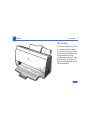
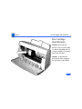
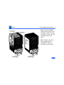
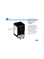
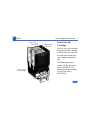
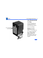
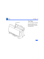
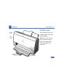
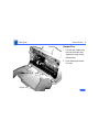
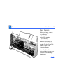
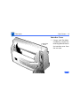
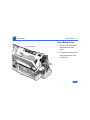
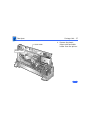
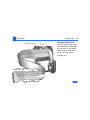
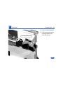
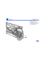
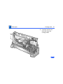
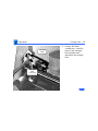
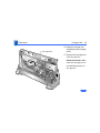
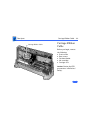
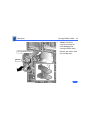
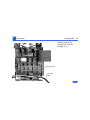
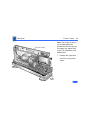
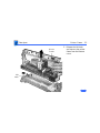
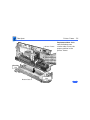
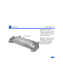
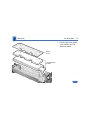
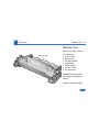
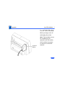
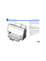
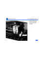
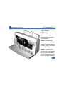
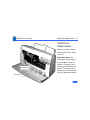
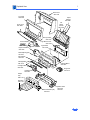
K Service Source
Color StyleWriter 2500
K Service Source
Basics
Color StyleWriter 2500
Basics
Overview - 1
Overview
The Color StyleWriter 2500
is a desktop color bubblejet printer for personal use.
It has various features such
as high-speed printing
(3 pages per minute), high
print quality, printing on
plain or coated paper, and a
cut sheet feeder.
Basics
Overview - 2
The Color StyleWriter 2500
can be configured with
• Four-color ink cartridge
• High-performance black
ink cartridge
• Color PhotoGrade ink
cartridge
Ink Tanks
All of these cartridges can be
easily replaced.
Note: The four-color
cartridge contains two ink
tanks that can be replaced
separately. One tank
contains black ink and the
other tank contains the
yellow, cyan, and magenta
Basics
Overview - 3
Error LED
Power LED
inks. Each tank can be
replaced separately.
The Color StyleWriter 2500
has two LEDs that can aid in
troubleshooting the printer.
See the Troubleshooting
chapter for more
information.
Basics
Ink Cartridge Identification - 4
Ink Cartridge
Identification
Ink Cartridge
Caution: Do not get the
printer’s ink on your hands
or clothes. Although the ink
is water soluble, it contains
dyes that will stain.
Caution: To prevent the
print heads from clogging,
do not touch or wipe them.
Basics
Four-Color
Ink Tank
Ink Cartridge Identification - 5
Note: Two ink cartridges
come with the printer. One
cartridge is black ink only;
the other is a four-color ink
cartridge with two ink
tanks.
Black-Only
Ink Tank
Note: These are the same
ink cartridges as the
StyleWriter 2400 ink
cartridges and ink tanks.
Four-Color
Ink Cartridge
Black-Only
Ink Cartridge
Basics
Ink Cartridge Identification - 6
High-Performance,
Black-Only Ink
Cartridge
Black–Only
Ink Cartridge
The black ink cartridge
contains black ink only. The
Service part number for
the black-only cartridge is
for service use only. To
order a replacement
cartridge for a customer,
use the finished goods part
number (M3240G/A).
Basics
Ink Cartridge Identification - 7
Four-Color
Ink Tank
Four-Color
Ink Cartridge
Black-Only
Ink Tank
Four-Color Ink
Cartridge
The four-color ink cartridge
holds two ink tanks. One tank
contains black ink only, and
the other tank contains the
cyan, magenta, and yellow
inks.
The finished goods part
number for the black-only
tank is M3330G/A. The
finished goods part number
for the color tank is
M3329G/A).
Basics
Ink Cartridge Identification - 8
Color PhotoGrade Ink
Cartridge
Color PhotoGrade
Ink Cartridge
The Color PhotoGrade ink
cartridge holds four ink
tanks and the print head in
an all-in-one design.
Important: The Color
PhotoGrade Print Kit
(M5577**/A) includes the
ink cartridge, PhotoGrade
paper, and PhotoGrade
Updater software. For
photorealistic results, the
kit contents must be used
together.
Basics
Ink Cartridge Identification - 9
Note: The ** designator in finished goods part number
M5577**/A varies due to localized software.
To order replacement supplies, use the following finished
goods part numbers:
• Color PhotoGrade Ink Cartridge (M5579G/A)
• Color PhotoGrade Paper, Letter-Size (M5578G/A)
• Color PhotoGrade Paper, A4-Size (M5581G/A)
Printing with the Color PhotoGrade Ink Cartridge
1
2
3
Install the PhotoGrade Updater software and the ink
cartridge as instructed in the user booklet titled Color
StyleWriter 2500 Color PhotoGrade Print Kit.
Load the PhotoGrade paper into the sheet feeder so the
whiter side faces you.
Open the document you want to print.
Basics
Ink Cartridge Identification - 10
4
5
6
PhotoGrade Selected
Select Print from the
File menu.
In the Print dialog box,
select PhotoGrade from
the Paper Type pop-up
menu.
Click Color.
Basics
Ink Cartridge Identification - 11
7
ColorSync On
Scatter Selected
8
9
In the Color Options
dialog box,
• Select Scatter for the
best blend of ink
• Turn on ColorSync
(Automatic) for the
best color matching
Click OK.
Click Print.
Basics
Test Page - 12
Online Key
Test Page
Turn on the printer and hold
down the online key for at
least 6 seconds or until the
test page prints.
Basics
Test Page - 13
The test page shows the ROM
revision and a test pattern.
Use the test pattern to
determine if the ink jets are
functioning properly. If
lines appear broken,
proceed to the “Printing”
topic in the Troubleshooting
chapter.
Note: There are two test
pages, one for the black-ink
only cartridge and one for
the four-color ink
cartridge.
Basics
Test Page - 14
Demo Test Page Units
The Color StyleWriter 2500
demo unit logic board ROM
contains a unique demo page.
A limited quantity are being
sold for use by Apple
resellers.
Note: The demo test page
printer may be serviced the
same as a regular 2500,
however, if the logic board
is replaced it will lose the
demo page capability. If that
feature is needed, the unit
should be RMAed to Finish
Goods.
K Service Source
Specifications
Color StyleWriter 2500
Specifications
Characteristics - 1
Characteristics
Print Methods
Throughput
Print Head
Serial bubble jet ink-on-demand
Up to three pages per minute with the high-performance black
ink cartridge
Up to 0.3 page per minute for color
Actual speed depends on the documents printed and the Macintosh
used
Four color cartridge: 136 nozzles (vertically-lined)
1 x 64 nozzles for black color
3 x 24 nozzles for yellow, magenta, cyan
Black cartridge: 128 nozzles (vertically-lined)
Specifications
Graphics - 2
Graphics
Resolution
Best: 720x360 dpi with optimized ink density for color,
greyscale, black and white
Normal: 360 x 360 dpi for color, greyscale, black and white
Draft: 180 x 180 dpi for faster printing
Specifications
Print Media - 3
Print Media
Paper
Plain paper, coated (recommended for color picture output)
Color PhotoGrade paper (required for photorealistic color output)
Envelopes
Commercial number 10, monarch, and other sizes
Capacity: 15 envelopes
Transparencies
Coated transparencies, most ink jet transparencies
Capacity: 20 sheets
Back-Print Film
Letter, A4
For superior graphics and imaging results, premium paper and
back-print film are recommended
Specifications
Cut Sheets
Print Media - 4
LTR, LGL, A4
U.S. Letter (LTR): 8.5 x 11 in. (215.9 mm x 279.4 mm)
U.S. Legal (LGL): 8.5 x 14 in. (215.9 mm x 355.6 mm)
A4: 210 mm x 297 mm
Weight: 16-24 lbs. Capacity: 100 sheets (A4, LTR);
20 sheets coated paper
Specifications
Ink Cartridges - 5
Ink Cartridges
Type
High-performance black ink cartridge with integrated ink tank
and print head
Four-color ink cartridge with two ink tanks (black only and
color—cyan, magenta, yellow) and integrated print head
Color PhotoGrade ink cartridge with four ink tanks and integrated
print head
Ink Color
Black
Four-color (Black, cyan, magenta, yellow)
Shelf Life
6 months (installed in printer)
18 months (in original package)
Specifications
Print Head
Cartridge Life
Ink Tank Life
Ink Cartridges - 6
Text: Approx. 900 pages (A4/LTR) high performance black only
Color: Approx. 1800 pages, with ink tank replacements
High performance black cartridge with integrated ink tank
900 pages at 5% coverage
Color ink tanks (Black or CMY)
100 pages at 7.5% coverage
Specifications
Environmental - 7
Environmental
Acoustic Noise Level
Approx. 45 dB (reference level)
Temperature
59–86°F (15-30°C)
Humidity
10–80% (no condensation)
Specifications
Electrical - 8
Electrical
Electrical
Requirements
Power Consumption
AC power adapter
U.S./Japan: 102-132 VAC, 60 Hz
UK/Australia: 204-264 VAC, 50 Hz
Europe: 196-253 VAC, 50 Hz
Japan: 85-110 VAC, 50,60 Hz
20 W maximum
Specifications
Physical - 9
Physical
Dimensions
Weight
Height: 8.3 in. (211 mm)
Width: 14.4 in. (365 mm)
Depth: 9.2 in. (234 mm)
6.9 lb (3.2 kg)
K Service Source
Troubleshooting
Color StyleWriter 2500
Troubleshooting
General/ - 1
General
The Symptom Charts included in this chapter will help you
diagnose specific symptoms related to your product. Because cures
are listed on the charts in the order of most likely solution, try
the first cure first. Verify whether or not the product continues to
exhibit the symptom. If the symptom persists, try the next cure.
(Note: If you have replaced a module, reinstall the original module
before you proceed to the next cure.)
If you are not sure what the problem is, or if the Symptom Charts
do not resolve the problem, refer to the Flowchart for the product
family.
For additional assistance, contact Apple Technical Support.
Troubleshooting
Error Messages and LEDs/ - 2
Error Messages and LEDs
The Color StyleWriter 2500 has two LEDs that can aid in
troubleshooting the printer: error LED and power LED.
Error LED
Power LED
Troubleshooting
Error Messages and LEDs/ - 3
The printer software also gives error messages to pinpoint
errors.
Make sure the printer is hooked up to a Macintosh and that the
Color StyleWriter 2500 software is installed. See the Diagnostics
folder on the Service Source CD for the printer driver.
Troubleshooting
Error Messages and LEDs/ - 4
The LEDs indicate the state of the printer or whether an error has occurred (e.g., carriage
control error, paper jam).
The following chart provides a summary of error codes and printer states. If an error is
indicated, check the chart, then go to “Error LEDs” in the Symptom Charts.
Software Error Message
(from printer driver)
LEDs
Error
Power
Symptom
(see Symptom Charts)
Out of paper
Paper pickup error
Paper jam
Paper jam
Ink cartridge jam
Carriage control error
Obstruction, clear and try again
Cleaning error
Check connector and try again
Temperature sensor error
Cartridge not installed properly
Cartridge error
Check connectors and try again
ROM/RAM error
Waste ink absorbers full
Waste ink full error
Cartridge needs to be replaced
Head temperature error
Cartridge needs to be replaced
Head temperature sensor error
Troubleshooting
Symptom Charts/Operation - 5
Symptom Charts
Operation
No power
1
2
3
Check power cable connections.
Replace power cord.
Check voltage of power adapter.
4
5
If there is no voltage, replace the power adapter.
If the voltage is within the specified range, replace the logic
board.
Troubleshooting
Does not print
Symptom Charts/Operation - 6
1
2
3
4
Turn on printer and restart computer.
Check interface cable connections.
Open Chooser and verify that correct printer driver and port
is selected.
Replace printer driver.
Carriage unit does not
move to center when
front door is open, and
printer is on
1
Carriage unit moves
back and forth for five
minutes
Print job was canceled during a purge.
back on.
2
Make sure black latch on upper left corner of front door
engages button on logic board. See “Front Covers” topic in
Take Apart for additional information.
Replace logic board.
Turn printer off, then
Troubleshooting
Printer will not print
with LocalTalk option
installed
Symptom Charts /Operation- 7
1
2
3
4
5
6
7
Turn on printer and restart computer.
Check interface cable connections.
Open Chooser and verify that correct printer driver and port
are selected.
Replace printer driver.
Check that printer is functional by printing a test page.
Try printing directly through serial port.
Replace LocalTalk module.
Troubleshooting
Symptom Charts/Paper - 8
Paper
Paper sticks together
1
2
3
4
Paper skews
1
2
3
4
Remove excess sheets from paper tray.
Use only specified paper, envelopes, transparencies, and
backprint film.
Check that settings in Page Setup menu are correct.
Fan paper before putting it in paper tray.
Remove excess sheets from paper tray.
Use only specified paper, envelopes, transparencies, and
backprint film.
Stack paper flush against left side of paper tray and adjust
paper guide.
Check rollers on sheet feeder and eject roller. Clean or
replace if necessary.
Troubleshooting
Symptom Charts /Paper- 9
Paper jams during
loading, before
printing
Carefully remove paper by hand.
Paper jams inside
printer
Carefully pull out paper in direction of paper output.
Paper jams during
output, after printing
1
2
Carefully pull out paper in direction of paper output.
Check eject roller for obstructions or damage, and clean or
replace if necessary.
Troubleshooting
Symptom Charts/Print Quality - 10
Print Quality
Missing dots and/or
white streaks
1
2
3
4
5
Blurring and/or
smudging
1
2
3
Missing dots followed
by a blob of ink
Perform “Nozzle Check” and “Print Head Cleaning.” See
Additional Procedures chapter.
Make sure ink cartridges are set firmly.
Use only specified paper, envelopes, transparencies, and
backprint film.
Replace ink cartridge. See Additional Procedures chapter.
Replace logic board.
Use only specified paper, envelopes, transparencies, and
backprint film.
Perform “Print Head Cleaning.” See Additional Procedures
chapter.
Replace ink cartridge. See Additional Procedures chapter.
Before printing, switch print quality to “Best” in printer driver.
Troubleshooting
Symptom Charts /Print Quality- 11
Vertical lines are
distorted/wavy
Open and close blue lever next to cartridge to make sure cartridge
is seated properly.
Poor image at bottom
of page
Increase margin at bottom of page to at least 0.8 inch.
Dark streaks or ink
stains when Color
PhotoGrade ink
cartridge used
Move internal paper selector to Envelope position (leaves more
space between print head and paper surface).
QuickDraw GX does
not work when Color
PhotoGrade ink
cartridge used
Disable QuickDraw GX before printing with Color PhotoGrade
Print Kit. The PhotoGrade Updater software does not support
QuickDraw GX.
Troubleshooting
Symptom Charts/Error LEDs - 12
Error LEDs
Paper pickup error
1
2
3
4
Add paper.
Use only specified paper, envelopes, transparencies, and
backprint film.
Check that settings in Page Setup menu are correct.
Fan paper before putting it in paper tray.
Paper jam
Check eject roller for obstructions or damage, and clean or
replace if necessary.
Carriage control
error
Check eject roller for obstructions or damage, and clean or
replace if necessary.
Cleaning error
Check eject roller for obstructions or damage, and clean or
replace if necessary.
Troubleshooting
Symptom Charts /Error LEDs- 13
Temperature sensor
error
1
2
Check cable connections.
Replace logic board.
Cartridge error
1
2
3
Make sure ink cartridges are set firmly.
Replace ink cartridge.
Replace carriage unit.
ROM/RAM error
1
2
3
Check cable connections.
Reinstall printer software.
Replace logic board.
Waste ink full error
Replace ink absorbers.
Head temperature
error
Replace ink cartridge.
Head temperature
sensor error
Replace ink cartridge.
K Service Source
Take Apart
Color StyleWriter 2500
Take Apart
Front Covers - 1
Front Covers
Front
Case
No preliminary steps are
required before you begin
this procedure.
Front
Door
Note: The “Front Covers”
topic includes the front
door, front case, output
tray, and output tray
extension.
Output Tray
Extension
Output Tray
Take Apart
Front Covers - 2
Front Door
Note: The front door is held
in place by two arms that
function as hinges. Plastic
tabs at the end of the arms
fit into knobs on the inside of
the upper case.
Front
Case
1
Arm Tab
2
Front
Door
3
Ê
Swing open the front
door.
Press the end of each
arm inward and free the
arm tabs from the front
case.
Lift off the front door.
Take Apart
Front Covers - 3
Replacement Note: The
small gears and springs in
the front door fall out of
position if a paper jam is
forcibly removed from the
printer. These gears and
springs are not available as
service replacement parts.
Small Gears
and Springs
Front Door
See the “Small Gear
Replacement” topic in
Additional Procedures.
Take Apart
Front Covers - 4
Front Case
1
2
Center
Latch
Right Side
Latch
Front
Case
3
Lift the center of the
case to release the center
latch on the front case.
Release the right side
latch and pull the front
case forward a short
distance.
Repeat for the left side
latch and remove the
case.
Take Apart
Front Covers - 5
Latch
On/Off
Button
Latch
Front
Case
Replacement Note: Make
sure the latches on the front
case engage the buttons on
the logic board.
Take Apart
Front Covers - 6
Output Tray
1
2
Tab
Output Tray
Pull out the output tray
until the two tabs rest
against the stops on the
bottom case.
Press down and remove
the tray.
Take Apart
Front Covers - 7
Output Tray Extension
1
2
Output Tray Extension
Pull out the tray
extension until the two
tabs rest against the
stops.
Press down and remove
the tray extension.
Take Apart
Eject Roller - 8
Eject Roller
Before you begin, remove
the covers (see “Front
Door”).
Eject Roller
Take Apart
Eject Roller - 9
Grasp one end of the roller,
press the bracket to the
side, and remove the eject
roller from the printer.
Eject Roller
Take Apart
Rear Covers
Rear Covers - 10
Rear Covers
Before you begin, remove
the following:
• Front covers
• LocalTalk module
(if present)
Note: For information on
removing the LocalTalk
module, see the “LocalTalk
Module” topic in the
Upgrades chapter.
Note: The “Rear Covers”
topic includes the rear case,
interface cover, and logic
board cover.
Take Apart
Rear Covers - 11
Rear Case
Latch
1
Rear Case
2
3
Plastic Lip
Pull out the bottom of
the rear case slightly to
clear the plastic lip.
Using a flat-blade
screwdriver, release the
latch and lift up the rear
case.
Repeat for the other side
of the case.
Take Apart
Rear Covers
Rear Covers - 12
4
Release the three
latches on the top of the
printer.
Take Apart
Rear Covers - 13
5
Rear Case
6
Tab
Tab
Lift up and release the
rear case from the two
tabs on the back of the
printer.
Remove the rear case.
Take Apart
Rear Covers - 14
Interface Cover
1
Interface
Cover
Mounting Tab
Using a small flat-blade
screwdriver, release the
mounting tab and remove
the interface cover from
the rear case.
Take Apart
Rear Covers - 15
Logic Board Cover
1
Front Latch
2
Side
Latch
Press in the front latch
and release the side
latch.
Pull back and remove the
logic board cover from
the printer.
Take Apart
Cut Sheet Feeder - 16
Cut Sheet Feeder
Cut Sheet Feeder
Before you begin, remove
the following:
• Front covers
• Rear covers
Caution: Review the ESD
precautions in Bulletins/
Safety.
Take Apart
Cut Sheet Feeder - 17
1
CNV
Connector
CNLF
Connector
Disconnect connectors
CNV and CNLF from the
logic board.
Take Apart
Cut Sheet Feeder - 18
2
Cut Sheet Feeder
Connector Wires
Slot
Remove the connector
wires from the slot on
the cut sheet feeder.
Take Apart
Cut Sheet Feeder
Cut Sheet Feeder - 19
3
4
Note: Make sure the
screws do not fall into
the bottom cover.
Using a Phillips
screwdriver, remove
the two screws that
secure the cut sheet
feeder to the printer.
Press in the latch and
remove the cut sheet
feeder.
Take Apart
Cut Sheet Feeder - 20
Replacement Note: Make
sure the alignment pins on
the cut sheet feeder are
aligned with the printer
frame.
Alignment
Pin
Alignment Pin
Take Apart
Paper Support - 21
Paper Support
Paper Support
Before you begin, remove
the following:
• Front covers
• Rear covers
• Cut sheet feeder
Caution: Review the ESD
precautions in Bulletins/
Safety.
Take Apart
Paper Support - 22
1
Paper Support
2
Latches
3
Pull out the paper
support until it rests
against the stops.
Push the support
forward and disconnect
the latches.
Slide out the paper
support.
Take Apart
Pickup Roller - 23
Cut Sheet Feeder
Pickup Roller
Before you begin, remove
the following:
• Front covers
• Rear covers
• Cut sheet feeder
Caution: Review the ESD
precautions in Bulletins/
Safety.
Pickup Roller
Take Apart
Pickup Roller - 24
Cut Sheet Feeder
1
2
Feeder Gear
Latches
Caution: When the roller
is removed, the feeder
gear is loose. Remove the
roller slowly so that the
gear will not fly off.
Press in the two latches
on the pickup roller and
push out the roller.
Remove the feeder gear
from the cut sheet
feeder.
Take Apart
Pickup Roller - 25
3
Pickup Roller
Cut Sheet Feeder
4
Lift up one end of the
roller and remove the
other end from the
mounting hole.
Remove the pickup
roller from the cut sheet
feeder.
Take Apart
Pickup Roller - 26
Notch
Notch
Upper Gear
Feeder Gear
Replacement Note: Align the
notch on the upper gear with
the upper line on the cut
sheet feeder. Align the notch
on the feeder gear with the
lower line on the cut sheet
feeder.
Take Apart
Logic Board - 27
Logic Board
Logic Board
Before you begin, remove
the following:
• Front covers
• Rear covers
• Cut sheet feeder
Caution: Review the ESD
precautions in Bulletins/
Safety.
Take Apart
Logic Board - 28
Upper Ink
Absorber
Lower Ink
Absorber
Note: Information on the
amount of ink absorbed by
the ink absorbers is stored
on the logic board EEPROM.
When replacing the logic
board, check the ink
absorbers. If the upper ink
absorber has ink in it,
replace it. Always replace
the lower ink absorber.
Take Apart
Logic Board - 29
Upper Ink
Absorber
Lower Ink
Absorber
If the ink absorbers have
been used for two weeks or
less, or if fewer than 50
pages have been printed, it
is not necessary to replace
the ink absorbers when
replacing the logic board.
See “EEPROM Reset” in
Additional Procedures for
more information.
Take Apart
Logic Board - 30
1
CNCR
CNH
CNV
CNLF
Disconnect the following
connectors from the
logic board:
• CNCR
• CNH
• CNLF
• CNV
Take Apart
Logic Board - 31
2
Logic Board
3
Using a Phillips
screwdriver, remove
the three mounting
screws.
Remove the logic board
from the printer.
Take Apart
Carriage Unit - 32
Carriage Unit
Carriage Unit
Before you begin, remove
the following:
• Front covers
• Rear covers
• Cut sheet feeder
Caution: Review the ESD
precautions in Bulletins/
Safety.
Caution: To prevent the
print nozzles from clogging,
do not touch or wipe them.
Take Apart
Carriage Unit - 33
Screw
Carriage Guide
Screw
Caution: Do not remove or
loosen the two screws on top
of the carriage guide.
Loosening or removing
these screws will cause the
carriage to go out of
alignment.
Take Apart
Carriage Unit - 34
1
Power Supply
Turn the printer so that
the power supply faces
you.
Take Apart
Carriage Unit - 35
2
CNH
Disconnect connector
CNH from the logic
board.
Take Apart
Carriage Unit - 36
3
Carriage Unit
Turn the printer so that
the carriage unit faces
you.
Take Apart
Carriage Unit - 37
Cable Holder
Ribbon Cable
4
Remove the plastic
ribbon cable and cable
holder from the printer.
Take Apart
Carriage Unit - 38
Carriage Unit
Tab
Ribbon
Cable Holder
Ribbon Cable
Holes
Replacement Note: Make
sure the ribbon cable holes
are mounted on the two tabs
on the inside of the ribbon
cable holder and the small
tab is in the slot on the
carriage unit.
Take Apart
Carriage Unit - 39
5
6
Carriage Release Clip
Press in the two latches.
Push up and remove the
carriage release clip
from the printer.
Take Apart
Carriage Unit - 40
7
Carriage
Shaft
Mounting
Screw
Using a Phillips
screwdriver, remove
the mounting screw from
the carriage shaft.
Take Apart
Carriage Unit - 41
8
Shaft
Clip
Carriage
Shaft
Carefully remove the
shaft clip from the
carriage shaft.
Take Apart
Carriage Unit - 42
9
Carriage
Belt
Carriage
Belt
Tensioner
Using a flat-blade
screwdriver, carefully
press in the carriage
belt tensioner and
disconnect the carriage
belt.
Take Apart
Carriage Unit - 43
Carriage Unit
10 Hold the carriage unit
and slide out the carriage
shaft.
11 Remove the carriage unit
from the printer.
Replacement Note: Make
sure the carriage unit is
reinstalled properly in
the printer.
Take Apart
Carriage Ribbon Cable - 44
Carriage Ribbon Cable
Carriage Ribbon
Cable
Before you begin, remove
the following:
• Front covers
• Rear covers
• Cut sheet feeder
• Ink cartridge
• Carriage unit
Caution: Review the ESD
precautions in Bulletins/
Safety.
Take Apart
Carriage Ribbon Cable - 45
1
Carriage Ribbon Cable
Sensor
Caution: Carefully
remove the sensor to
avoid damaging the
carriage ribbon cable.
Remove the sensor from
the carriage unit.
Take Apart
Carriage Ribbon Cable - 46
2
Ribbon Cable
Guide
Press in the five latches
and remove the ribbon
cable guide.
Take Apart
Carriage Ribbon Cable - 47
Carriage Unit
Tab
3
Remove the ribbon cable
from the carriage unit.
Replacement Note: Make
sure the ribbon cable
holes are mounted on the
two tabs on the inside of
the ribbon cable holder
and the small tab is in
the slot on the carriage
unit.
Ribbon
Cable Holder
Ribbon Cable
Holes
Take Apart
Carriage Belt - 48
Carriage Belt
Carriage Belt
Before you begin, remove
the following:
• Front covers
• Rear covers
• Cut sheet feeder
• Ink cartridge
• Carriage unit
Caution: Review the ESD
precautions in Bulletins/
Safety.
Take Apart
Carriage Belt - 49
Carefully remove the
carriage belt from the
carriage unit.
Carriage Unit
Carriage
Belt
Take Apart
Carriage Belt Tensioner - 50
Carriage Belt
Tensioner
Carriage
Belt
Tensioner
Before you begin, remove
the following:
• Front covers
• Rear covers
• Cut sheet feeder
Caution: Review the ESD
precautions in Bulletins/
Safety.
Take Apart
Carriage Belt Tensioner - 51
1
Carriage
Belt
Carriage
Belt
Tensioner
Using a flat-blade
screwdriver, carefully
press in the carriage
belt tensioner and
disconnect the carriage
belt.
Take Apart
Carriage Belt Tensioner - 52
2
Carriage
Belt
Tensioner
Slide out the carriage
belt tensioner from the
printer.
Take Apart
Printer Frame - 53
Printer Frame
Printer Frame
Before you begin, remove
the following:
• Front covers
• Rear covers
• Cut sheet feeder
• Power supply
Caution: Review the ESD
precautions in Bulletins/
Safety.
Take Apart
Printer Frame - 54
Note: The printer frame is
not a replaceable part.
Remove the frame to access
the purge unit, paper feed
motor, ink absorbers, and
bottom case.
Printer Frame
1
Right
Latch
Release the right latch
and lift up the printer
frame.
Take Apart
Printer Frame - 55
Printer
Frame
Left
Latch
2
Release the left latch
and remove the printer
frame from the bottom
cover.
Take Apart
Printer Frame - 56
Printer Frame
Circular
Tab
Bottom Case
Circular
Tabs
Replacement Note: Make
sure the bottom case
circular tabs fit into the
proper position in the
printer frame.
Take Apart
Paper Feed Motor - 57
Paper Feed Motor
Before you begin, remove
the following:
• Front covers
• Rear covers
• Cut sheet feeder
• Power supply
• Printer frame
Caution: Review the ESD
precautions in Bulletins/
Safety.
Paper Feed Motor
Take Apart
Paper Feed Motor - 58
1
Logic Board
CNLF
Paper Feed Motor
Disconnect connector
CNLF from the logic
board.
Take Apart
Paper Feed Motor - 59
Platen Bracket
2
Move the platen bracket
away from the mounting
screw.
Take Apart
Paper Feed Motor - 60
3
4
Note: Carefully remove
the paper feed motor to
avoid losing the gear.
Using a Phillips
screwdriver, remove
the two mounting
screws.
Remove the paper feed
motor from the printer.
Take Apart
Paper Feed Motor - 61
5
Gear
Paper
Feed
Motor
Remove the gear from
the paper feed motor.
Take Apart
Carriage Motor - 62
Carriage Motor
Carriage
Motor
Before you begin, remove
the following:
• Front covers
• Rear covers
• Cut sheet feeder
Caution: Review the ESD
precautions in Bulletins/
Safety.
Take Apart
Carriage Motor - 63
1
CNCR
Disconnect connector
CNCR from the logic
board.
Take Apart
Carriage Motor - 64
2
Carriage
Belt
Carriage
Belt
Tensioner
Using a flat-blade
screwdriver, press in
the carriage belt
tensioner and disconnect
the carriage belt.
Take Apart
Carriage Motor - 65
3
4
Carriage
Motor
Using a Phillips
screwdriver, remove
the two mounting
screws.
Lift up and pull out the
carriage motor.
Take Apart
Purge Unit - 66
Purge Unit
Before you begin, remove
the following:
• Front covers
• Rear covers
• Cut sheet feeder
• Power supply
• Printer frame
Caution: Review the ESD
precautions in Bulletins/
Safety.
Purge
Unit
Take Apart
Purge Unit - 67
1
Carriage Unit
Purge
Unit
Move the carriage unit
away from the purge
unit.
Take Apart
Purge Unit - 68
2
Using a Phillips
screwdriver, remove
the black mounting
screw.
Take Apart
Purge Unit - 69
3
Locking Lever
Purge
Unit
Pull back the locking
lever and remove the
purge unit from the
printer.
Take Apart
Purge Unit - 70
Replacement Note: Make
sure the black lever
interlocks with the platen
assembly in the position
shown.
Lever
Take Apart
Ink Absorbers - 71
Ink Absorbers
Ink Absorbers
Before you begin, remove
the following:
• Front covers
• Rear covers
• Cut sheet feeder
• Power supply
• Printer frame
Caution: Review the ESD
precautions in Bulletins/
Safety.
Take Apart
Ink Absorbers - 72
Ink Absorbers
Caution: Do not get the
printer’s ink on your hands
or clothes. Although the ink
is water soluble, it contains
dyes that will stain.
Note: After replacing the ink
absorbers, you must reset
the EEPROM on the logic
board. See the Additional
Procedures chapter.
Take Apart
Ink Absorbers - 73
1
Plastic
Cover
Ink Absorber
Plates
Remove the clear plastic
cover and the two ink
absorber plates.
Take Apart
Bottom Case - 74
Bottom Case
Bottom Case
Before you begin, remove
the following:
• Front covers
• Rear covers
• Cut sheet feeder
• Logic board
• Power supply
• Printer frame
• Ink absorbers
Caution: Review the ESD
precautions in Bulletins/
Safety.
Perform the above steps.
Take Apart
Bottom Case - 75
Note: A replacement bottom
case includes feet.
If necessary, replace
damaged or missing feet.
Feet
Feet
K Service Source
Upgrades
Color StyleWriter 2500
Upgrades
LocalTalk Module - 1
LocalTalk Module
Before you begin, turn off
and unplug the printer.
LocalTalk
Module
Note: This procedure covers
the installation of an
optional LocalTalk module,
which enables the printer
to connect to a LocalTalk
network.
Upgrades
LocalTalk Module - 2
Note: There are two
versions of this module that
look similar. The latest
version states on the label
that it works with both the
2400 and 2500. The earlier
version only works with the
2400.
Upgrades
LocalTalk Module - 3
1
Interface
Cover
Using a small flat-blade
screwdriver, release the
mounting tab and remove
the interface cover from
the rear case.
Upgrades
LocalTalk Module - 4
2
LocalTalk
Connector
Plug the LocalTalk
connector into the serial
port.
Upgrades
LocalTalk Module - 5
3
LocalTalk
Module
Insert the upper edge of
the LocalTalk module
into the rear case, and
then snap the bottom into
place.
Upgrades
EtherTalk Adapter - 6
EtherTalk Adapter
Before you begin, turn off
and unplug the printer.
Note: This procedure covers
the installation of an
optional EtherTalk adapter,
which enables the printer
to connect to a Ethernet
network.
Serial Cable
EtherTalk
Adapter
Upgrades
EtherTalk Adapter - 7
1
2
Serial Cable
EtherTalk
Adapter
Plug the serial cable
from the printer into the
EtherTalk Adapter.
Plug in the EtherTalk
power adapter.
K Service Source
Additional Procedures
Color StyleWriter 2500
Additional Procedures
Printer Covers
Printer Cleaning - 1
Printer Cleaning
Before you begin, unplug the
printer.
Caution: Do not use
ammonia-based or alcoholbased cleaners on or around
the printer. These cleaners
may react with the plastic.
Caution: Do not spill liquid
in the power cord
receptacle.
Additional Procedures
Printer Covers
Printer Cleaning - 2
1
Caution: Do not get the
printer’s ink on your
hands or clothes.
Although the ink is water
soluble, it contains dyes
that will stain.
Using a damp cloth,
wipe the outside of the
printer covers.
Additional Procedures
Printer Cleaning - 3
2
3
Rollers and Platen
Front Door
Caution: Do not use any
liquid cleaners inside the
printer.
Open the front door of
the printer.
Using a dry cloth,
carefully wipe the
rollers and platen.
Additional Procedures
Ink Cartridge Replacement - 4
Ink Cartridge
Replacement
Ink Cartridge
No preliminary steps are
required before you begin
this procedure.
Caution: Do not get the
printer’s ink on your hands
or clothes. Although the ink
is water soluble, it contains
dyes that will stain.
Additional Procedures
Ink Cartridge
Ink Cartridge Replacement - 5
Note: This procedure covers
the ink cartridge
replacement for either of
the ink cartridges that come
with the printer. One
cartridge is black ink only;
the other is a four-color ink
cartridge with two ink
tanks. One tank contains
black ink only and the other
tank contains the cyan,
magenta, and yellow inks.
Additional Procedures
Ink Cartridge
Ink Cartridge Replacement - 6
The Service part number for
the black-only cartridge is
for service use only. To
order a replacement
cartridge for a customer,
use the finished goods part
number (M3240G/A).
Additional Procedures
Ink Cartridge Replacement - 7
1
2
Carriage Unit
Front Door
Turn on the printer.
Open the front cover. The
carriage unit will now
move to the center
position.
Additional Procedures
Ink Cartridge Replacement - 8
3
Blue Lever
Raise the bright blue
lever on the carriage
unit and remove the
cartridge.
Additional Procedures
Ink Cartridge Replacement - 9
4
Caution: To prevent the
print heads from
clogging, do not touch or
wipe them.
Remove the bright
orange cap from the
replacement ink
cartridge.
Bright Orange Cap
Additional Procedures
Ink Cartridge Replacement - 10
5
Bright Orange Tape
Peel off the bright
orange tape from the
print heads.
Additional Procedures
Ink Cartridge Replacement - 11
6
7
Ink Cartridge
Install the replacement
ink cartridge into the
printer.
Close the printer cover.
Additional Procedures
Ink Tank Replacement - 12
Ink Tank
Replacement
Ink Tanks
No preliminary steps are
required before you begin
this procedure.
Caution: Do not get the
printer’s ink on your hands
or clothes. Although the ink
is water soluble, it contains
dyes that will stain.
Additional Procedures
Four-Color
Ink Tank
Four-Color
Ink Cartridge
Ink Tank Replacement - 13
Black-Only
Ink Tank
Note: This procedure covers
ink tank replacement for the
four-color ink cartridge.
The cartridge contains two
separate ink tanks, one for
black ink and one for cyan,
magenta, and yellow inks.
When you run out of ink, you
replace only the empty tank,
instead of replacing the
entire cartridge.
Additional Procedures
Ink Tank Replacement - 14
1
Turn on the printer.
3
Remove and discard the
old ink tank.
2
Ink Tanks
Open the front cover. The
carriage unit will now
move to the center
position.
Additional Procedures
Ink Tank Replacement - 15
4
Ink Tank
Caution: To prevent the
print heads from
clogging, do not touch or
wipe them.
Remove the plastic cap
from the replacement
ink tank.
Plastic Cap
Additional Procedures
Ink Tank Replacement - 16
5
Ink Tank
6
Ink Cartridge
Caution: Make sure you
install the color ink tank
on the left and the black
ink tank on the right.
Slide the ink tank into
the ink cartridge and
push down so the ink
tank snaps into place.
Close the printer cover.
Additional Procedures
Nozzle Check - 17
Nozzle Check
No preliminary steps are
required before you begin
this procedure.
Caution: Do not get the
printer’s ink on your hands
or clothes. Although the ink
is water soluble, it contains
dyes that will stain.
Additional Procedures
Ink Cartridge
Nozzle Check - 18
Note: This procedure
explains how to run the
nozzle check test page,
which indicates whether the
print nozzles need to be
cleaned. The print nozzles
are contained in the ink
cartridge.
Additional Procedures
Nozzle Check - 19
1
Power Button
Power LED
2
Important: Make sure the
printer is off.
Load paper into the cut
sheet feeder.
Hold down the power key
until the power LED
starts blinking. The
printer will now print
out a test page.
Additional Procedures
Nozzle Check - 20
3
Examine the bottom of
the test page to
determine print head
status.
If the horizontal lines in
the test pattern are
missing, one or more ink
nozzles are clogged. To
clear the nozzles,
perform one of the print
head cleaning procedures
described in this
chapter.
Additional Procedures
Print Head Cleaning - 21
Print Head
Cleaning
No preliminary steps are
required before you begin
this procedure.
Caution: Do not get the
printer’s ink on your hands
or clothes. Although the ink
is water soluble, it contains
dyes that will stain.
Caution: To prevent the
print nozzles from clogging,
do not touch or wipe them.
The print nozzles are on the
bottom of the ink cartridge.
Additional Procedures
Print Head Cleaning - 22
Note: Use the Cleaning
option to correct blurred
characters, horizontal white
streaks, and missing dots
caused by clogged ink
nozzles. Use the Super
Cleaning option when print
quality does not improve
after you have performed
the Cleaning option two or
three times.
Additional Procedures
Print Head Cleaning - 23
1
2
3
4
Make sure the Color
StyleWriter 2500
printing software is
installed. See the
Diagnostics folder on
Service Source for the
driver software.
Using the Chooser, select
Color StyleWriter
2500.
Make sure the correct
printer port is selected.
Close the Chooser.
Additional Procedures
Print Head Cleaning - 24
5
6
Open any document and
select the print option or
choose Print Window
from the File menu.
Click the Utilities button
in the Print dialog box.
Additional Procedures
Print Head Cleaning - 25
7
8
ISelect the “Clean the
print head before
printing” option.
Click OK.
Additional Procedures
EEPROM Reset - 26
EEPROM Reset
Logic Board
with EEPROM
No preliminary steps are
required before you begin
this procedure.
Note: This procedure
explains how to perform the
EEPROM reset, which
clears data stored on the
logic board. It is necessary
to perform this procedure
after replacing the ink
absorbers or the logic board.
See “Logic Board” and “Ink
Absorbers” in Take Apart
for more information.
Additional Procedures
Four-Color
Ink Tank
Four-Color
Ink Cartridge
EEPROM Reset - 27
Note: This procedure uses
either the black-only or the
four-color ink cartridge.
Black-Only
Ink Tank
Black-Only
Ink Cartridge
Additional Procedures
EEPROM Reset - 28
1
2
3
Front Door
Disconnect the power
cord from the printer.
Make sure the ink
cartridge is installed and
the power cord is
plugged into the wall.
Open the front door.
Additional Procedures
EEPROM Reset - 29
4
Power Button
5
Front Door
Press and hold down the
power button while
connecting the power
cord to the printer, and
then release the power
button.
Close the front door.
Additional Procedures
Upper Corner of Pattern Page
EEPROM Reset - 30
6
Note: A pattern page now
prints and the EEPROM
data is reset. The last
bar on the pattern will
be white, which shows
that the data has been
reset.
Press the power button
to turn off the printer
and then disconnect the
power cord from the
printer.
Additional Procedures
Small Gear Replacement - 31
Small Gear
Replacement
Before you begin, remove
the front door (see “Front
Covers”)
Small Gears
and Springs
Front Door
Replacement Note: The
small gears and springs in
the front door fall out of
position if a paper jam is
forcibly removed from the
printer. These gears and
springs are not available as
service replacement parts.
Ê
Additional Procedures
Small Gear Replacement - 32
Small Gear
Spring
Replacement Note: The
springs in the small gear
fall out easily. Make sure
the springs are not lost or
damaged. These gears and
springs are not available as
service replacement parts.
Additional Procedures
Small Gear Replacement - 33
1
Front Door
Arm Tab
Arm Tab
Turn the front door so
that the arm tabs face
toward you.
Additional Procedures
Small Gear Replacement - 34
2
Small Gear
Spring
3
Groove
Tab
4
Place the gear and spring
in the front cover and
wrap one end of the
spring around the tab on
the front cover.
Set the spring into the
groove.
Repeat for the other end
of the spring.
Additional Procedures
Small Roller Replacement - 35
Small Roller
Replacement
No preliminary steps are
required before you begin
this procedure.
Small Roller
Replacement Note: The
small rollers in the platen
assembly fall out of position
if a paper jam is forcibly
removed from the printer.
These small rollers are not
available as service
replacement parts.
Additional Procedures
Small Roller Replacement - 36
1
2
Platen Cover
3
Small Roller
Lift up the platen cover.
Note: There is a small
mounting groove on the
underside of the platen
cover.
Slip the small roller
under the top of the
platen.
Push up and snap the
roller into the groove
under the platen cover.
K Service Source
Exploded View
Color StyleWriter 2500
Exploded View
1
Rear Cover
922-1910
Top Case
922-1909
Paper
Support
922-2065
Cut
Sheet
Feeder
922-1903
Front Cover
922-1908
Pick-Up Roller
922-1914
Power Adapter
922-2194
Paper Feed Motor
922-1906
Logic Board Cover
922-1915
Logic Board
661-1038
Roller &Spring (Kit)
076-0471
Eject Roller
922-1913
Carriage Belt
922-1146
Carriage Motor
922-1907
Carriage Cable
922-1904
Purge Unit
922-1143
Carriage Unit
922-1912
Output
Tray
922-1139
Extension
922-1138
Ink Absorbers (Kit)
076-0470
Bottom Case
with Feet
922-1911