1
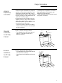
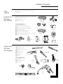
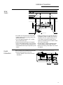
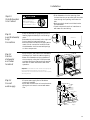
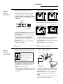
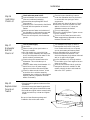
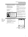
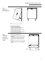
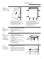
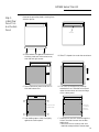
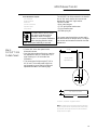
GE Monogram® Installation Instructions with Optional Trim Kit Installation Instructions CleanSensor Dishwashers Models ZBD3500 BB ZBD3500 WW Before you begin—Read these instructions completely and carefully. IMPORTANT: Save these instructions for local inspector’s use. IMPORTANT: OBSERVE ALL GOVERNING CODES AND ORDINANCES. NOTE TO INSTALLER: Be sure to leave these instructions with the Consumer. NOTE TO CONSUMER: Keep these instructions with your Use and Care Book for future reference. CAUTION WARNING This appliance must be properly grounded. See “Power Supply”, page 9. If the dishwasher is a new installation, most of the work must be done before the dishwasher is moved into place. If this dishwasher is replacing another dishwasher, the connections must be checked for compatibility and replaced as necessary. If you have a question concerning the installation of this product, call the GE Answer Center® Consumer Information Service at 800.626.2000, 24 hours a day, 7 days a week. If you received a damaged dishwasher, you should immediately contact your dealer or builder. WARNINGS: • This dishwasher must be installed to allow for future removal from the enclosure if service is required. • Use this appliance only for its intended purpose. Contents Design Information Models Available ................................................................. 3 Dimensions & Clearances .................................................. 3 Advance Planning ................................................................ 4 Standard Installation in 24" Deep Cabinets .................... 4 Standard Installation in 25" Deep Cabinets .................... 4 Side-by-Side Installation .................................................... 5 Optional Panel Kits and Custom Panel Kits .................... 5 Corner Installation ............................................................... 5 Installation Preparation Parts Supplied ...................................................................... 6 Materials You Will Need ..................................................... 6 Tools You Will Need ............................................................. 6 Single Dishwasher ............................................................... 7 Double Dishwasher ............................................................. 7 Double Dishwashers Divider Panel Preparation ........... 7 Water Supply ........................................................................ 8 Double Dishwashers ........................................................... 8 Power Supply ........................................................................ 9 Prepare Drain Plumbing ................................................... 10 Double Dishwashers ......................................................... 10 Installation Step 1, Check Door Balance ............................................ 11 Step 2, Remove Wood Base ............................................. 11 Step 3, Loosen Leveling Legs .......................................... 11 Installation of this dishwasher requires basic mechanical and electrical skills. Proper installation is the responsibility of the installer. Product failure due to improper installation is not covered under the GE Appliance Warranty. See the Use & Care Guide for warranty information. For Monogram local service in your area, 1-800-444-1845. For Monogram Parts and Accessories, call 1-800-626-2002. Step 4, Remove Access Panel and Toekick .................. 12 Step 5, Install Power Cord (if used) ................................ 12 Step 6, Install 90° Elbow ................................................... 12 Step 7, Position Water Line and Power Supply ........................................................... 13 Step 8, Insert Drain Hose ................................................. 13 Step 9, Install Optional Trim Kits and Tub Flange ........ 13 Step 10, Slide Dishwasher into Cabinet ........................ 14 Step 11, Level Dishwasher, Align Connections ............ 14 Step 12, Position Dishwasher and Fasten to Cabinet . 14 Step 13, Connect Water Supply ...................................... 14 Step 14, Connect Drain Line ............................................. 15 Step 15, Connect Power Supply ...................................... 15 Step 16, Installation Check List ....................................... 16 Step 17, Dishwasher Wet Test ........................................ 16 Step 18, Replace Access Panel and Toekick ............... 16 Trim Kits GPF100 Trim Kit, Heavy Door Springs ............................ 17 GPF400, GPF600, GPF700, Door and Access Panel Kits .................................................... 18 GPF400S, Stainless Steel Door and Access Panels .......................................................... 20 GPF425, 1/4" Custom Panels ............................................ 22 GPF475, 3/4" Custom Panels ............................................. 25 GPF53, Mounting Brackets .............................................. 29 2 Design Information CleanSensor Dishwashers Models Available ZBD3500 WW White CleanSensor dishwasher ZBD3500 BB Black CleanSensor dishwasher Designed for versatility, the Monogram builtin dishwasher adapts easily to virtually any installation. Dimensions & Clearances (Both Models) A – 34" min. adjustable to 35" max. B – 24" C – 25" total depth (including 1/4" thick insulation at rear) D – 4" toekick E – 4-1/2" escutcheon height F – 3-1/4" G – 24-3/4" from cabinet face (depending on depth of cabinets) C G B E A Toekick F D 3 Design Information CleanSensor Dishwashers Advance Preplanning Information • These Monogram dishwashers are supplied as either a white or black model. Door and access panels may be covered with custom decorative panels of wood or other materials to match cabinetry or other appliances. See “Optional Trim Kits,” page 5. • A custom toekick can be installed over the supplied toekick to match cabinet material when cabinet depth is 25" or more. A continuous toekick may be installed to form an unbroken line at floor level. –A continuous toekick should be installed in such a manner that it can be removed if service is required. Standard Installation In 24" Deep Cabinets • Install in standard 24" deep cabinets: –The dishwasher door will extend approximately 1/4" beyond the front face of adjacent cabinetry. Standard Installation In 25" Deep Cabinets • Install in standard 25" deep cabinets: –The dishwasher door will be flush with the front face of the cabinetry. – Use shims to set the cabinets out from the wall. • Tub flange trim is supplied to conceal any slight gap between the dishwasher and adjacent 24" deep cabinetry. • These dishwashers may be installed beneath any type of countertop. Cabinet Depth 24" Cabinet Resting Against Wall 1" Cabinet Shim Depth 24" 4 Design Information CleanSensor Dishwashers Side-by-side Installation • Two Monogram dishwashers may be installed side-by-side for greater capacity. Optional Panel and Custom Panel Kits Custom Panel Kits • GPF425 Trim Kit – Provides for the installation of 1/4" thick custom door and access panels. • GPF475 Trim Kit – Provides for the installation of 3/4" thick custom door and access panels. This kit includes GPF100 heavy springs kit for panels that weigh over 4 pounds. Panel Kits • GPF400S Trim Kit – Stainless steel door and access panels. • GPF400B, GPF400W Trim Kits – Black or white color change or replacement door and access panel. • GPF600B, GPF600W Trim Kits – Black or white replacement door panel only. Corner Installation • GPF700B, GPF700W, Trim Kits – Black or white replacement access panel only. Installation Kits • GPF100 Heavy Spring Kit – Heavy duty springs for custom door panels weighing 4 to 8 pounds. This spring kit is included with the GPF475 trim kit for 3/4" thick panels and the GPF400S stainless steel panel kit. • GPF53 Mounting Kit – Special brackets for installing dishwasher beneath countertops of stone or other materials that will not accept screws. • For a corner installation, allow 2" clearance between dishwasher and adjacent cabinet or wall. • Dishwasher must be placed no more than 10 feet from sink for proper drainage. Top View–Corner Installation Dishwasher 24-3/4" Countertop Door in Open Position 2" Minimum To Clear Drawer or Door Handles 5 Installation Preparation CleanSensor Dishwasher Parts Supplied ■ Two Phillips head countertop mounting screws taped to dishwasher. Materials You Will Need: (Not Supplied) ■ 90° elbow (3/8" NPT external thread on one end and opposite end to fit hot water supply line) ■ Thread seal tape ■ UL listed wire nuts (3) For new installations only: ■ Air gap for drain hose, if required ■ Waste tee for house plumbing, if applicable ■ Electrical cable or power cord, if applicable ■ Screw type hose clamps ■ Strain relief for electrical connection ■ Hand shut-off valve (recommended) ■ Water line 3/8" O.D. min. copper or 1/2" O.D. min plastic. ■ Coupler to join additional drain hose Air Gap Wire Nuts Electrical Cable or Power Cord 90° Elbow Screw Type Clamps Thread Seal Tape Hot Water Line Shut-Off Valve Waste Tee Strain Relief Materials You Will Need: (Not Supplied) ■ ■ ■ ■ ■ ■ ■ ■ Phillips head and flat blade screwdrivers Adjustable wrench (6") 3/8", 5/16" and 1/4" nut drivers Level Carpenter’s square Measuring tape Safety Glasses Safety glasses Coupler Flat Blade Screwdriver Nut Driver Phillips Head Screwdriver Flashlight For new installation only: ■ Tubing cutter ■ Drill and appropriate bits ■ Hole saw set Hole Saw Set Adjustable Wrench Turbing Cutter Flashlight Measuring Tape Drill and Bits Level Square 6 Installation Preparation CleanSensor Dishwasher Single Dishwasher • The rough cabinet opening must be 24" min. deep and 24" wide. The opening height should be 34" min. and 35" max. • The opening should be free of extraneous pipes and wires. 34-1/2"±1/4" Underside of Countertop to Floor This Wall Area must be Free of Pipes or wires 5" 4" 24" Min. 5" 4" Plumbing and Electric Services Must Enter Inside This Area 6" Cabinets Square and Plumb 24" Min. Double Dishwasher When installing double dishwashers, side-by-side: –The opening should be 48" wide. –Depth and height are the same as for single unit. 48" Min. Double Dishwashers Divider Panel Preparation • A divider panel must be used for double, side-by-side installations. –The divider must be supplied by the installer at the time of installation. Locate the divider panel in the center of the 48" opening. –Attach the divider panel to the floor, countertop and rear wall. 24" 24-1/4" 34-1/2" 1/8" Thick Masonite 5" 2" 7 Installation Preparation CleanSensor Dishwasher Water Supply 1-1/2" Dia. Hole Shut-off Valve 4" 5" 4" 5" Hot 2" from Cabinet Cabinet Face • Hot water line may enter from either side, from the rear, or from the floor within the shaded area shown. • Cut a hole approximately 1-1/2" in diameter to admit water line. • Install a hand shut-off valve in the supply line in an accessible location, such as under the sink. (The shut-off valve is optional, but recommended and may be required by local codes.) Double Dishwashers When installing two dishwashers side-by-side, route the water supply line as shown. –Follow installation instructions for each dishwasher. 6" 19" from Wall 2" from Floor • Water connection is on the left side of the dishwasher. Install hot water line using no less than 3/8" O.D. copper tubing or 1/2" O.D. plastic tubing. Route water line as shown and extend the line forward at least 19" from the rear wall. • Allow at least 2" clearance between water line and adjacent cabinet wall as shown. • Before connecting, flush water line to clean out debris. Water Supply For 2-Dishwasher Installation Cut Off Valve Optional 5" 4" 5" 5" 4" 5" 4" 6" 1/2" O.D. Copper Recommended To Here Toe Space 24" 48" Min. 8 Installation Preparation CleanSensor Dishwasher Power Supply WARNING FOR PERSONAL SAFETY: REMOVE HOUSE FUSE OR OPEN CIRCUIT BREAKER BEFORE BEGINNING INSTALLATION. DO NOT USE AN EXTENSION CORD OR ADAPTER PLUG WITH THIS APPLIANCE. FOLLOW NATIONAL ELECTRICAL CODES OR PREVAILING LOCAL CODES AND ORDINANCES. Electrical Requirements: These dishwashers must be supplied with a 120 volt, 60 Hz power supply with an individual, properly grounded branch circuit, protected by a 15 or 20 amp fuse or circuit breaker or time delay fuse. • A side-by-side dual dishwasher installation requires two separate circuits. • Wiring must be 2 wire with ground. • If electrical supply does not meet the above requirements, call a licensed electrician before proceeding. Grounding Instructions: This appliance must be either connected to a grounded-metal permanent wiring system, or an equipment-grounding conductor must be run with the circuit conductors and be connected to the equipment-grounding terminal or lead on the appliance. WARNING THE IMPROPER CONNECTION OF THE EQUIPMENT - GROUNDING CONDUCTOR CAN RESULT IN A RISK OF ELECTRIC SHOCK. CHECK WITH A QUALIFIED ELECTRICIAN OR SERVICE REPRESENTATIVE IF YOU ARE IN DOUBT WHETHER THE APPLIANCE IS PROPERLY GROUNDED. Double Dishwashers • When installing two dishwashers side-by-side, place electrical supply for each dishwasher as shown in diagram for single dishwasher installation. • A side-by-side dual installation requires two separate circuits. Alternate Receptacle Location 18" Receptacle Location Area 18" 6" 1-1/2" Dia. Hole (Max.) 4" 5" 5" 4" 3" 6" from Cabinet 6" 24" from Wall Ground Black White Cabinet Preparation & Wiring: • Wiring may enter from either side, the rear, or from the floor within the shaded area shown. • Cut hole 1-1/2" max. dia. within the shaded area to admit the electrical cable or power cord. The hole must be free of sharp edges. If the cabinet wall partition is metal, the edge of the hole must be covered with a rubber protector. Electrical Connections: The electrical connection is on the right side of the dishwasher. • For cable direct connections, the cable must be routed as illustrated. The cable must extend forward a minimum of 24" from the rear wall. • For power cord connections, install a 3prong type receptacle in the rear wall of sink cabinet next to the dishwasher. Install the receptacle at least 6" and not more than 18" from the opening and off the floor. • Allow approximately 3" between cable and adjacent cabinetry. Electrical Supply For 2-Dishwasher Installation 5" 5" 4" 5" 4" 5" 4" 6" Toe Space 24" 48" Min. 9 Installation Preparation CleanSensor Dishwasher Prepare Drain Plumbing • Follow local codes and ordinances. • Dishwasher drain hose must not exceed 10 feet in length for proper drainage. –The dishwasher is supplied with a 1/2" I.D. drain hose, 78" long. Add up to 42" length to the factory supplied hose if necessary. • Dishwasher must be connected to waste line with an air gap (not supplied) or 32" minimum, high drain loop (depending on local codes and ordinances) to prevent back flow into the dishwasher. • An air gap must be used if waste tee or disposer connection is less than 18" above floor to prevent siphoning. • Install waste tee or disposer and air gap according to the manufacturer’s instructions. Method 1 – Air Gap with Waste Tee or Disposer Use this method when waste tee or disposer connection is less than 18" above the floor. Waste Tee Installation Disposer Installation Method 2 – High Drain Loop with Waste Tee or Disposer Use this method when high drain loop is at least 32" above the floor. • Cut a hole in cabinet wall, approximately 1-1/2" in diameter for drain hose. CAUTION An air gap MUST BE USED if the drain hose is connected to waste tee or disposer lower than 18" above the floor level. Failure to provide the proper drain connection height, 18", with air gap or 32" minimum high drain loop will result in improper draining of the dishwasher which may cause damage. Double Dishwashers • When installing two dishwashers side-by-side, place drain hoses and air gaps as shown. –Follow the same installation instructions as for single dishwasher. Note: Each dishwasher must have a separate drain hose as shown. 32" Min. 18" Min. 32" 18" Min. Min. Waste Tee Installation Disposer Installation • Provide a method to attach drain hose to underside of countertop. Attachment will be made in later step. Water Supply For 2-Dishwasher Installation Air Gaps 7/8" I.D. Hose Cut Off Valve Optional 1/2" O.D. Copper Recommended To Here 7/8" I.D. Hose 5" 5" 4" 5" 4" 5" 4" 6" Toe Space 24" 48" Min. 10 Installation CleanSensor Dishwasher Step 1 Check Door Balance CAUTION Do not remove wood base until you are ready to install the dishwasher. The dishwasher will tip over when the door is opened. • Unlatch door and remove all foam and cardboard packaging. • Check balance by opening and closing door. If necessary, close latch and adjust one or both springs before the wood base is removed. Note: Spring hook must be turned to the outside. Move spring hook back to increase tension. Step 2 Remove Wood Base • Remove the 4 hex-head screws holding the dishwasher to the wood base inside the “U” frame. Discard screws and base. Remove and discard 3/8" Hex Head Screws • Locate and remove the yellow tape holding 2 Phillips to the top or side of the dishwasher. These screws are for securing the dishwasher to the countertop. Set aside for later installation. Caution: Do not attempt to remove the wood base by prying off or “kicking”. This will cause damage to the dishwasher base. Step 3 Loosen leveling legs Move the dishwasher close to the installation location and lay on its back. • Loosen the 4 leveling legs with an adjustable wrench and unscrew approximately 3/4". Approx . 3/4" 11 Installation CleanSensor Dishwasher • Remove the two screws below the access panel and set aside. • Loosen the two screws located between the door and access panel. Do not attempt to remove these screws. They are secured to the access panel with washers. es s Pa ne l Back Out 2 Screws To ek ick Ac c Step 4 Remove Access Panel And Toekick Remove 2 Screws Step 5 Install Power Cord (If Used) Skip this step If dishwasher will be wired direct. Step 6 Install 90° Elbow • Remove the junction box cover and install strain relief and power cord. The power cord and connections must comply with the national Electrical Code, Section 422 and/or local codes and ordinances. • The cord must be no longer than 6 ft. from the junction box to the receptacle. Note: Check That Harness Leads Are Threaded Thru Small Hole in Bracket White Neutral Ground Black Live • Connect incoming wires, white to white, black to black and ground to green wire. Use UL listed wire nuts of appropriate size. • Replace the junction box cover. Check to be sure wires are not pinched under the cover. • The water valve requires 3/8" NPT fitting with external threads. The opposite end should fit water supply line. • Install the 90° elbow fitting to the water valve using thread seal tape. • Position the end of the elbow to face the rear of the dishwasher. Caution: Do not bend the dishwasher frame when installing the 90° elbow fitting to the water valve. This could cause the door spring to come in contact with the fill hose. 90° Elbow Thread Seal Tape 12 Installation CleanSensor Dishwasher Step 7 Position Water Line And Power Supply • Position the water supply line and wiring on the floor of the opening to avoid interference with base and components under dishwasher. Water Line Step 8 Insert Drain Hose Step 9 Install Optional Trim Kits And Tub Flange Trim Kit. • Stand the dishwasher upright and move to the front of the opening. • Insert drain hose into the hole previously drilled in the cabinet wall. • If a power cord is used, guide the end through a separate hole. • The power cord should be routed directly to the rear of junction box. Avoid contact with side spring or other components. Power Supply Electric Water • If desired, install optional door and access panel kits following their installation instructions. • Locate the tub trim packed inside the dishwasher. • Press the trim onto the tub flange on each side. Start even with the top edge and press in as you move to the bottom. • Press trim piece onto top dishwasher flange. • Open and close the door to check that trim does not bind. 13 Installation CleanSensor Dishwasher Step 10 Slide Dishwasher Into Cabinet Step 11 Level Dishwasher, Align Connections Step 12 Position dishwasher and fasten to cabinet CAUTION DO NOT PUSH AGAINST FRONT DOOR PANEL WITH KNEES. Damage to the door panel will occur. • Level the dishwasher by adjusting the four leveling legs individually for correct alignment. • Dishwasher should be level, left to right and front to back for best performance. • Route the water and electrical supply within reach of their connection locations under the dishwasher. Avoid contact with springs or other components. • Slide dishwasher into the opening a few inches a time. As you proceed, pull the drain hose through the opening and under the sink. • Make sure drain hose is not kinked under the dishwasher. • Check to be sure there is no interference with water line and wiring. Rear View Water Electric • Open the door and position the dishwasher tub flange 3/4" from the cabinet opening. • Fasten the dishwasher to the underside of the countertop, using the 2 Phillips screws provided. Be sure screws are driven straight and flush to avoid interference with door operation. 3/4" Important: The dishwasher must be centered in the opening and have no interference when opening or closing the door. Interference may cause a water leak or make noise when opening and closing the door. Step 13 Connect water supply • Connect water supply line to 90° elbow previously installed. • Open and close the door to insure that door springs do not come in contact with water line. Fill Hose Door Spring 90° Elbow Hot Water Supply 14 Installation CleanSensor Dishwasher Step 14 Connect Drain Line Follow all local codes and ordinances. • The molded end of the drain line is designed to fit 5/8", 3/4" and 1" diameter connections to air gap, waste tee or disposer. • Cut on marked line as required for your installation. Cutting Lines 1" 3/4" 5/8" Do not cut corrugated portion of hose Step 15 Connect Power Supply Method 1 – Air gap with waste tee or disposer Waste Tee installation Disposer Installation Method 2- High drain loop with waste tee or disposer Fasten to underside Fasten to underside of countertop of countertop 32" 18" Min. Min. 18" Min. • The drain hose supplied is 78" long. If the location requires a longer drain hose, add up to 42" length. • Use 5/8" or 7/8" I.D. hose and short section of copper water line (not supplied) of appropriate length and diameter to connect the two ends. • Secure the connection with appropriate clamps (not supplied). • Connect the drain line to air gap, waste tee or disposer as previously determined. • Secure connection using appropriate clamps (not supplied). • Make sure drain hose is not kinked. Note: Total drain hose length must not exceed 10 feet for proper drain operation. Note: Remove drain plug before connecting to a disposer. Dishwasher cannot drain if plug is left in place. Verify that power is turned off at the source. WARNING CAUTION If house wiring is not 2-wire with a ground wire, a ground must be provided by the installer. When house wiring is aluminum, be sure to use U.L. listed anti-oxidant compound and aluminum-tocopper connectors. • If a power cord is used, plug into the outlet. • If dishwasher is wired directly to house wiring: –Remove junction box cover. –Secure the power supply cable to the back of the junction box with a strain relief (not supplied). Disposer Installation Waste Tee installation Note: Check That Harness Leads Are Threaded Thru Small Hole in Bracket White Neutral Ground Black Live • Locate the 3 dishwasher wires with stripped ends. Insert wires through the small hole in the junction box. • Use wire nuts to secure incoming white to white, black to black and ground wire to green. • Replace junction box cover, checking to be sure that wires are not pinched. 15 Installation CleanSensor Dishwasher Step 16 Installation Check List ■ Check to be sure power is OFF. ■ Open dishwasher door and remove all foam and cardboard packaging. ■ Remove literature package with Use & Care manual. ■ Read the Use & Care manual to familiarize yourself with the operation of the dishwasher. ■ Add two quarts of water to the bottom of the dishwasher to lubricate the pump seal. ■ Remove the protective film, if present, from the control panel, door and access panels. ■ Check to be sure that wiring is secure under the dishwasher and not pinched or in contact with door springs or other components. ■ Pull lower rack about half way out. Check to be sure it does not roll back into dishwasher or further out. If it does, the dishwasher needs to be leveled. ■ Turn on water supply. ■ Check for plumbing leaks. Tighten connections if necessary. ■ Turn on the hot water faucet at the sink. Water temperature at dishwasher must be between 120° and 150°F. Step 17 Dishwasher Wet Test Check List ■ Turn on power supply. ■ Latch door. ■ Select normal cycle on push button or electronic models. ■ On dial models, turn control dial just enough to start dishwasher. Be careful not to turn the dial past the first water fill. On electric models, push start pad. ■ Check to be sure that water enters the dishwasher. This could take up to 4 minutes. ■ Check for leaks under the dishwasher. If a leak is found, turn off power supply, tighten connections and restore power. ■ Check for leaks around the door. A leak around the door could be caused by dishwasher door rubbing or hitting against adjacent cabinetry. Reposition the dishwasher if necessary. ■ The dishwasher will drain for about 5 minutes after the first fill. Check drain lines. If leaks are found, turn off power, correct as necessary and restore power. ■ Open dishwasher door and make sure most of the water has drained. If not, check that disposer plug has been removed and/or air gap is not plugged. ■ Let the dishwasher run through another fill and drain cycle. Check again to be sure there are no leaks. ■ At the end of the second drain, push the reset pad on electronic models. On dial models, unlatch the door and rotate the dial to the “OFF” position. Step 18 Replace Access Panel And Toekick • Place the toekick against the bottom of the dishwasher. • Place the access panel assembly against the dishwasher and tighten the attached screws. • Re-install two original bottom screws loosely. Adjust the toekick up or down and tighten screws. Be sure to leave literature package and installation instructions with owner. Tighten 2 Access Panel Screws Access Panel Toekick Attachment Screws 16 GPF100 Trim Kit Heavy Door Springs Tools and Materials required: • 1/4" socket driver • Phillips screwdriver • Gloves to protect against sharp edges For installation of a custom dishwasher door panel weighing 4 pounds to 8 pounds. WARNING To prevent electric shock, disconnect electrical power supply to dishwasher before changing panels. Do not operate dishwasher while changing panels or when lower access panel assembly is removed. Step 1 • Turn off water supply. • Latch dishwasher door. Step 2: Remove Lower Access Panel Assembly • Remove the two screws below the access panel. Retain screws. • Loosen the two screws located between the door and the access panel. Do not attempt to remove these screws. They are secured to the access panel with washers. • Remove the access panel assembly and toekick from the dishwasher. Set aside. Loosen 2 Screws Access Panel Toekick Step 3: Replace Springs Remove old springs • Grasp the end of the spring at the rear of the dishwasher and release the hook. • Release opposite end of the spring and remove. Install door springs • Hook new GPF100 door spring on the end of the door frame. • Stretch the spring to the second hole in the channel. • Repeat the same procedure for the opposite side. • Hold the dishwasher with one hand and slowly open the door fully. • Open and close the door to check for proper balance. Correct spring tension should prevent the door from raising by itself from a full open position and prevent the door from falling heavily. • If the door falls heavily, increase spring tension by moving the hook further away from yourself. Test for proper balance. Repeat the procedure if necessary. • Re-install the toekick and access panel. Move spring hook back to increase tension. Note: Spring hook must be turned to the outside. 17 GPF400/600/700 Series Trim Kits Door and Access Panel Kits GPF400B, Black door and access panels GPF400W, White door and access panels GPF600B, Black door panel GPF600W, White door panel GPF700B, Black access panel GPF700W, White access panel Tools and Materials required: • 1/4" socket driver • Phillips screwdriver • Safety Glasses • Gloves to protect against sharp edges WARNING To prevent electric shock, disconnect electrical power supply to dishwasher before changing panels. Do not operate dishwasher while changing panels or when lower access panel assembly is removed. Step 1: Remove Lower Access Panel Assembly • Remove the two screws below the access panel. Retain screws. • Loosen the two screws located between the door and the access panel. • Remove the access panel assembly from the dishwasher and discard. (For GPF600, set access panel aside.) • Remove the toekick and set aside. The GPF400 series trim kit is designed to provide a color change or to conceal minor damage to original dishwasher door and access panels. The new door panel cover provided in this kit is designed to completely cover the existing dishwasher door. Do not remove the original door panel. 2 screws are provided for easy installation. This kit also provides a replacement access panel assembly. The original access panel assembly should be removed, discarded and replaced with this piece. The GPF600 trim kit provides the door panel only. Follow the same instructions presented here to install the door panel. The GPF700 trim kit provides an access panel only. Follow the same instructions presented here to install the access panel. Escutcheon Door Panel Note: Do not remove the insulation behind the toekick. Loosen 2 Screws Access Panel Toekick 18 GPF400/600/700 Series Trim Kits Door and Access Panel Change Step 2: Install New Door Panel Cover New Door Pane l Cover Note: The new door panel cover will completely cover the existing door. Do not remove the original door panel. For GPF400 and GPF600 Kits: • Remove protective plastic film. • Tip door panel and slide up and under bottom and sides of escutcheon. • Snap door panel over the door and slide upwards, under the escutcheon. • Drive 2 screws into the bottom of the panel using a phillips head screwdriver. Step 3: Install New Access Panel Assembly And Toekick • Remove protective plastic film. • Place the toekick against the bottom of the dishwasher. • Place the new access panel assembly against the dishwasher and tighten the attached screws. (GPF600, re-install original access panel.) • Re-install two original bottom screws loosely. Adjust the toekick up or down and tighten screws. Tighten 2 Screws 19 GPF400S Trim Kit Stainless Steel Door and Access Panels Tools and Materials required: • 1/4" socket driver • Phillips screwdriver • Electric drill • 1/8" drill bit • Safety glasses • Center punch • Gloves to protect against sharp edges The GPF400S Stainless steel trim kit covers the existing door and access panel. This kit includes: • Door and access panel covers. • 12 screws. • GPF100 Spring kit WARNING CAUTION To prevent electric shock, discon- nect electrical power supply to dishwasher before changing panels. Do not operate dishwasher while changing panels or when lower access panel assembly is removed. Step 1 • Remove the two screws below the access panel. Retain screws. • Loosen the two screws located between the door and the access panel. • Remove the access panel assembly from the dishwasher. • Remove plastic screw retainers holding the screws to the access panel. Save screws and retainers. • Remove the toekick and set aside. NOTE: Do not remove the insulation behind the access panel or toekick. To Clean These Stainless Steel Panels: Stainless steel has some unique cleaning characteristics. In order to keep your dishwasher looking like new we suggest cleaning it with Stainless Steel Magic or a similar product. Escutcheon Door Panel Loosen 2 Screws Access Panel Toekick Stainless Steel Magic is available at Ace, True Value, Servistar, HWI and other leading stores. It is also available through GE Parts by calling 1-800-626-2002 and ordering part number WX10X15. 20 GPF400S Trim Kit Stainless Steel Door and Access Panels Step 2: Install Stainless Door Panel Cover New Door Pane l Cover • Remove protective plastic film. • Tip door panel and slide up and under bottom and sides of escutcheon. • Snap door panel over the door and slide upwards, under the escutcheon. Step 3: Install GPF100 Spring Kit This kit must be installed to achieve proper door balance which is affected by the addition of this stainless door panel. • Follow the instructions provided with the GPF100 kit. Step 4: Install Stainless Access Panel Onto Access Panel Assembly • Remove protective plastic film. • Locate and install 2 original screws and retainers into the top holes of the stainless access panel. • Place the stainless access cover on the access panel assembly. • Drive 3 screws through the bottom of stainless cover. • Center punch and drill one hole into each side of the stainless cover. • Install screws supplied. Step 5: Install Access Panel Assembly • Place the toekick against the bottom of the dishwasher. • Place the access panel assembly against the dishwasher and tighten the attached screws. • Re-install two original bottom screws loosely. Adjust the toekick up or down and tighten screws. • Drive 3 screws into the bottom of the panel using a phillips head screwdriver. • Center punch and drill holes through the holes in the stainless panel and into the dishwasher door, 2 on each side. • Install screws supplied. Retainers Cover Tighten 2 Screws 21 GPF425 Series Trim Kit 1/4" Custom Panels GPF425B, Black Trim Kit GPF425W, White Trim Kit GPF425A, Almond Trim Kit Tools and Materials required: • 1/4" socket driver • Phillips screwdriver • Electric drill • 1/8" drill bit • Masking tape • Safety glasses • Gloves to protect against sharp edges Step 1: Cut 1/4" Thick Custom Panel To Size The GPF425 trim kits provide for the installation of 1/4" thick custom door and access panels. This kit includes: • Left, right and bottom door trim • Top and bottom access panel trim • Color matched screws WARNING CAUTION To prevent electric shock, discon- nect electrical power supply to dishwasher before changing panels. Do not operate dishwasher while changing panels or when lower access panel assembly is removed. • Cut door panel and access panel to the dimensions shown. NOTE: The trim provided will conceal the cut edges of the panels. 1/4" Thick Door Panel 19-3/4" 1/4" Thick Access Panel 3-11/16" 23-9/16" Step 2: Remove Lower Access Panel Assembly • Remove the two screws below the access panel. Retain screws. • Loosen the two screws located between the door and the access panel. Do not attempt to remove these screws. They are secured to the access panel with washers. • Remove the access panel assembly from the dishwasher. • Remove the toekick and set aside. NOTE: Do not remove the insulation behind the access panel or toekick. Escutcheon Door Panel Loosen 2 Screws Access Panel Toekick 22 GPF425 Series Trim Kit 1/4" Custom Panels Step 3: Install Door Panel Trim And Custom Panel Remove the protective plastic covering from side trim pieces. “Z” Trim A. Place bottom trim against the bottom of the door panel and drive center screw, then left and right screws. B. Slide “Z” shaped trim under the escutcheon. C. Slide custom door panel under the “Z” trim and bottom trim. D. The notch on the side trim pieces go towards the front. Slide side trim up and under the escutcheon and over the edge of the custom panel. Drill Holes and Install Screws E. Use masking tape to hold trim tightly against the custom panel. Tape Trim To Custom Panel on Each Side F. Center punch and drill holes through the holes in the side trim and into the dishwasher door. • Secure the trim to the door with color matched screws provided. Remove tape. 23 GPF425 Series Trim Kit 1/4" Custom Panels Step 4: Install Custom Access Panel • Place bottom trim against the bottom of the access panel. • Install color matched screw in the center, then left and right screws. • Gently, bend both ends of the bottom trim upwards to form a “U” shape. • Slide the 1/4" custom panel down into “U” shaped trim. • Place top trim over the panel. Use masking tape to hold in place. • Drill 3 holes into the top of the trim and into the assembly. Install 3 color matched screws provided. • Drill holes through the side trim holes and into the access panel. Secure each side of the trim with one screw. Remove tape. Install Center Screw First Step 5: Install Access Panel Assembly And Toekick • Place the toekick against the bottom of the dishwasher. • Place the access panel assembly against the dishwasher and tighten the attached screws. • Re-install two original bottom screws loosely. Adjust the toekick up or down and tighten screws. Installation Options This trim kit is designed to accommodate 1/4" thick panels. A raised panel screwed or glued to 1/4" thick backing can be used. The raised portion of the panel must be fabricated 1/4" to permit clearances for the trim on all sides. Thick Tighten 2 Screws Panel • “X” Clearance shown at the bottom of the raised panel must be maintained to prevent the door from striking the access panel when opened. Appearance Panel Backing 3/4" 1/4" 1/2" 1/4" Total Thickness 1" 3/4" “X” Clearance 2" 1-7/8" A 3/4" thick custom panel may be installed by routing the top and sides to 1/4" thickness. The bottom edge, Dimension “X”, should be and 1-1/2" high and 1/4" thick. 1/4" Min. Clearance 1/8" Min. Clearance Appearance Panel 19-3/4" 1/8" Min. Clearance X Clearance 23-9/16" Access Panel 1/4" Min. Clearance All Sides 3-11/16" 23-9/16" IMPORTANT! GPF100 Dishwasher Door Spring Kit MUST BE installed when custom door panels weigh 4 pounds or more. 24 GPF475 Series Trim Kit 3/4" Custom Panels Tools and Materials required: • 1/4" socket driver • Phillips screwdriver • Electric drill • 1/8" and 3/16" drill bits • Carpenters square • Safety Glasses The GPF475 Trim Kit provides for the installation of 3/4" thick custom door and access panels with a typical 4" high toekick. This Kit includes: • Door panel support • 5, 5/8" phillips flat head screws • 3 round head screws • GPF100 spring kit. WARNING CAUTION To prevent electric shock, discon- nect electrical power supply to dishwasher before changing panels. Do not operate dishwasher while changing panels or when lower access panel assembly is removed. Step 1: Cut 3/4" Thick Custom Panels The custom panels should be constructed in the same manner as cabinet doors. Cut edges can be seen and must be finished for the best appearance. • Cut the 3/4" thick door panel to the dimensions shown. • Rout the bottom edge of the door panel on the appearance side, 1/2" deep and 1-1/2" high resulting in 1/4" thickness. See illustration. • The access panel height may be 3-3/4" to 4-1/4" max. The access panel height can vary depending upon toekick height and adjustments made to the leveling legs. 23-5/8" 3/4" Thick Panel Appearance Side 19-7/8" 3/4" 1-1/2" 1/2" A* 3/4" Thick Access Panel 23-5/8" *3-3/4" min., 4-1/4" max. for typical 4" toekicks. Note: The custom wood access panel should evenly match the bottom of adjacent cabinets. Adjustments made to the leveling legs to obtain correct height can affect the vertical dimension (height) of the access panel. 25 GPF475 Trim Kit 3/4" Custom Panels Step 2: Remove Lower Access Panel Assembly • Remove the two screws below the access panel. Retain screws. • Loosen the two screws located between the door and the access panel. Do not attempt to remove these screws. They are secured to the access panel with washers. • Remove the access panel assembly and toekick from the dishwasher. Set aside. Escutcheon Door Panel NOTE: Do not remove the insulation behind the access panel or toekick. Loosen 2 Screws Access Panel Toekick Step 3: Mount Custom Panel To Metal Support Panel Tabs Overlap Bottom Edge Metal Support Overlaps Top Edge Tab Adhesive Strips Both Sides A. Lay the custom panel on a flat surface with appearance side down. • Measure and mark the center line. Use a carpenters square to draw the center line. B. Place the metal door panel support on the custom panel, with the projecting tabs overlapping and against the bottom edge. Center the support panel by matching the center line to the triangle cutout. NOTE: Do not remove tape from adhesive strips. 26 GPF475 Trim Kit 3/4" Custom Panels Step 3 (continued) Remove Tape Covering Adhesive Strips Screw Holes for Vertical (Typical) Wood Grain Screw Holes for Horizontal Wood Grain Direction C. Remove the custom panel from the support. • Remove tape from adhesive strips on the metal support – on the side that touches the custom panel. • Carefully, position the metal support onto the custom panel with center line showing through the triangle. Press the metal support against the panel. D. Determine the direction of the wood grain. • Drill 1/8" dia. pilot holes, 5/8" deep through the hole in the support according to the direction of the wood grain. See illustration. • Install 2 flathead screws through the support and into the panel. Caution: Do not drill pilot holes too deeply to avoid damaging the appearance side of the panel. Custom Pane l Install 3 Round Head Screws E. Remove tape from adhesive strips on the back side of the metal support. • Carefully, mount the panel onto the dishwasher by tipping the protruding metal at the top under and up against the escutcheon. Step 4 Install GPF100 Spring Kit F. Secure the panel to the door by installing 3 round head screws into the bottom of the metal support and into the dishwasher door. Install center screw first, then left and right screws. • Press the custom panel against the dishwasher door. This kit must be installed to achieve proper door balance which is affected by the addition of a heavy custom door panel. • Follow the instructions provided with the GPF100 kit. 27 GPF475 Trim Kit 3/4" Custom Panels Step 5 Install Custom Panel To Access Assembly • Drill 3 holes 3/16" dia. into the access panel as shown. • Place the custom panel onto the access assembly and mark hole locations. • Drill 3 holes, 1/8" dia. holes, 5/8" deep into the custom panel. • Align the custom panel with screw holes and drive 3 screws into the back side of the assembly panel and through the custom panel. The top edges should align evenly. 1/2" to 2" 1/2" to 2" 1/2" to 2" 3/16" Dia. Three Places Center Line 1/2" to 2" Caution: Do not drill pilot holes too deeply to avoid damaging the appearance side of the panel. Step 6 Install Access Panel Assembly And Toekick • Place the toekick against the bottom of the dishwasher. • Place the access panel assembly against the dishwasher and tighten the attached screws. • Re-install two original bottom screws loosely. Adjust the toekick up or down and tighten screws. Tighten 2 Screws 28 GPF53 Mounting Kit Mounting Brackets Tools and materials required: • 5/16" nut driver • Phillips screwdriver • Safety glasses Position Mounting Brackets • Fold factory installed flanges back 180° and flatten against tub frame. • Position mounting brackets over frame and in recessed area, as shown. Secure Mounting Brackets • Measure width of cabinet opening. • Insert two 10/32" machine screws into each bracket. Do not tighten. • Adjust brackets to match the cabinet opening width. • Tighten screws against metal frame. Finalize Installation • If necessary preparations for plumbing and electrical connections have been completed, slide dishwasher into place. • Secure each mounting bracket to adjacent cabinets with one screw. The GPF53 mounting kit is to be used for attaching dishwashers to adjacent cabinets when countertops are stone or other materials which will not accept screws. Fold Flanges Back 180° and Flatten Against Tub Frame Adjust To Cabinet Opening 29 Notes 30 Notes 31 NOTE: While performing installations described in this book, safety glasses or goggles should be worn. To obtain specific information concerning any Monogram product or service, call GE Answer Center® consumer information service at 800.626.2000—any time, day or night. For Monogram local service in your area, call 1-800-444-1845. ® Monogram. General Electric Company Louisville, KY 40225 NOTE: Product improvement is a continuing endeavor at General Electric. Therefore, materials, appearance and specifications are subject to change without notice. Pub. No. 49-5850 1998 GE Appliances (N.D. 977) 5/98