1
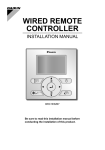
WIRED REMOTE CONTROLLER INSTALLATION MANUAL MODEL BRC1E51A7 Be sure to read this installation manual before conducting the installation of this product. 00_CV_EM08A086_EN.indd 1 4/7/2009 7:31:25 PM Contents 1. Safety Precautions ............................ 2 2. Accessories ....................................... 4 3. Remote controller installation procedure .......................................... 4 4. Functions and menu items of remote controller buttons .......... 10 5. Power-on .......................................... 12 6. Field setting method ....................... 13 7. Test operation method (in the case of SkyAir) .................... 16 8. Checking procedure of error record ..................................... 19 9. Registration method of the service contract .............................. 20 10. Confirmation of registered details ............................................... 21 11. Clock Setting ................................... 22 12. Language changeover .................... 22 English 01_EN_EM08A086.indd 1 1 4/7/2009 7:32:06 PM 1. Safety Precautions Also see installation manual attached to the indoor unit. Please read these “Safety Precautions” carefully before installing air conditioning equipment and be sure to install it correctly. ● The precautions described herein are classified as WARNING and CAUTION. They both contain important information regarding safety. Be sure to observe all precautions without fail. WARNING CAUTION Failure to follow these instructions properly may result in personal injury or loss of life. Failure to observe these instructions properly may result in property damage or personal injury, which may be serious depending on the circumstances. ● After completing installation, conduct a trial operation to check for faults and explain to the customer how to operate the air conditioner and take care of it with the aid of the operation manual. Ask the customer to store the installation manual along with the operation manual for future reference. WARNING Ask your dealer or qualified personnel to carry out installation work. Do not attempt to install the remote controller yourself. Improper installation may result in water leakage, electric shocks or fire. Consult your local dealer regarding relocation and reinstallation of the remote controller. Improper installation work may result in leakage, electric shocks or fire hazards. Install the remote controller in accordance with the instructions in this installation manual. Improper installation may result in water leakage, electric shocks or fire. Be sure to use only the specified accessories and parts for installation work. Failure to use the specified parts may result in the unit falling, water leaakage, electric shocks or fire. Install the remote controller on a foundation strong enough to withstand the weight of the remote controller. A foundation of insufficient strength may result in the remote controller falling and causing injury. Electrical work must be performed in accordance with relevant local and national regulations and with instructions in this installation manual. Be sure to use a dedicated power supply circuit only. Insufficiency of power circuit capacity and improper workmanship may result in electric shocks or fire. Always perform installation work with the power supply shut-off. Touch with energized electric parts causes an electric shock. Do not disassembly, reconstruct or repair. Electric shock and/or fire are caused. Make sure that all wiring is secured, the specified wires are used, and that there is no strain on the terminal connections or wires. Improper connections or securing of wires may result in abnormal heat build-up or fire. The choice of materials and installations must comply with the applicable national and international standards. 2 01_EN_EM08A086.indd 2 English 4/7/2009 7:32:06 PM CAUTION To avoid leakage and electric shock due to entry of water or insects, fill the wiring through hole with putty. To avoid electric shocks, do not operate with wet hands. Do not wash the remote controller with water, as this may result in electric shocks or fire. Install the indoor and outdoor units, power cord and connecting wires at least 1 meter away from televisions or radios to prevent picture interference and noise. (Depending on the incoming signal strength, a distance of 1 meter may not be sufficient to eliminate noise.) Do not install the air conditioner in the following locations: 1. Where there is a high concentration of mineral oil spray or vapour (e.g. a kitchen). Plastic parts will deteriorate, parts may fall off and water leakage could result. 2. Where corrosive gas, such as sulphurous acid gas, is produced. Corroding of copper pipes or soldered parts may result in refrigerant leakage. 3. Near machinery emitting electromagnetic radiation. Electromagnetic radiation may disturb the operation of the control system and result in a malfunction of the unit. 4. Where flammable gas may leak, where there is carbon fibre or ignitable dust suspensions in the air, or where volatile flammables such as paint thinner or gasoline are handled. Operating the unit in such conditions may result in fire. 5. High temperature area or directly flamed point. Heating and/or firing may be caused. 6. Moist area, or place where may be exposed to water. If water enters inside of the remote controller, electric shock may be caused and inner electronics may fail. When remote controller thermo function is used, select the installation location considering the followings. ● A place where average temperature in the room can be detected. ● A place where is not exposed to direct sunlight. ● A place where is far apart from heat source. ● A place where is not affected by outside air due to door opening/closing or the like. English 01_EN_EM08A086.indd 3 3 4/7/2009 7:32:06 PM 2. Accessories The following accessories are included. Wood screw Small screw (φ3.5×16) (M4×16) (2 pcs.) (2 pcs.) Clamp Manual CD Quick Reference Wiring retainer (1 pc.) (1 pc.) (1 pc.) (1 pc.) 3. Remote controller installation procedure 3-1 Determine where to install the remote controller. Make sure to follow “ 1. Safety Precautions” when determining the location. 3-2 Make a wiring through hole on the wall if the wires are taken out from the back side. External view of the remote controller F8-10 Set the center of the wall hole to the center of the wiring thro ugh hole on the controller lower case when making the hole. 40 Lower case Through hole 48.5 Through hole F8-10 CAUTION If the hole size is too large or the location is not proper, the hole may come out from the controller. 3-3 Remove upper case. Insert a screwdriver in the recess of lower case to remove the upper case (2 points). Remote controller PC-board is installed on the upper case. Take care not to damage the PC-board with the screwdriver. Take care that dust or moisture does not touch the PC-board of removed upper case. 4 01_EN_EM08A086.indd 4 Upper case Screwdriver Insert and twist the screwdriver lightly for removal. Lower case English 4/7/2009 7:32:07 PM 3-4 Determine the direction of controller wiring outlet (back outlet, left outlet, upper center outlet, upper outlet). 3-4-1 Back outlet 3-4-2 Left outlet Cut off resin area (hatched area). Cut off thin area (hatched area) with nippers or the like, and then remove burr with a file or the like. 3-4-3 Upper outlet 3-4-4 Upper center outlet Cut off thin area (hatched area) with nippers or the like, and then remove burr with a file or the like. Cut off thin area (hatched area) with nippers or the like, and then remove burr with a file or the like. 3-5 Conduct wiring. CAUTION 1. Switch box and transmission wiring are not attached. 2. Do not directly touch the remote controller PC-board. Wiring Specifications Wiring Type Wiring Size English 01_EN_EM08A086.indd 5 Sheathed vinyl cord or cable 0.75-1.25mm² 5 4/7/2009 7:32:08 PM Sheath part in the remote controller case should be stripped. Peel the shield and sheath Ca. 10mm For easy wiring, it is better to keep ca. 10mm difference between the length of two wires. Cutting guideline of the wiring Sheath stripping length: ● Ca. 150mm for upper outlet ● Ca. 200mm for upper center outlet Connect the terminals (P/P1, N/P2) of the remote controller upper case with the terminals (P1, P2) of the indoor unit. (P1 and P2 have no polarities.) 3-5-1 Back outlet Indoor unit P1 P2 Lower case Upper case PC-board Clamp Clamp Cross-section Wiring fixing point - Secure the wiring at the wiring fixing point by using attached clamping material. <Wiring fixing guideline> 6 01_EN_EM08A086.indd 6 English 4/7/2009 7:32:09 PM 3-5-2 Left outlet Indoor unit P1P2 Lower case Upper case PC-board 3-5-3 Upper outlet Wiring retainer Upper case Wiring retainer Wiring Cross-section - Install attached wiring retainer to prevent wiring pinch according to left figure. Indoor unit P1P2 Lower case Upper case PC-board 3-5-4 Upper center outlet Indoor unit P1P2 Wiring retainer Lower case Upper case PC-board English 01_EN_EM08A086.indd 7 7 4/7/2009 7:32:09 PM CAUTION ● Perform wiring apart from a power line not to receive electrical noise (external noise) during the wiring. ● Seal wiring draw-in port securely with putty (field supply) to prevent entry of insects or the like. 3-6 Fixing procedure of lower case. In the case of wiring center upward drawing or rearward drawing, see wiring procedure first as wiring with the case is needed before fixing. 3-6-1 In the case of installation on the wall Secure by using attached wood screws (2 pcs.). Wood screws (F3.5×16) 3-6-2 In the case of installation on the switch box Secure by using attached small screws (2 pcs.). Switch box for two units (with no cover) 84 Switch box (field supply) (Use optional accessory KJB211A) 46 (Installation pitch) Small screws (M4×16) 8 01_EN_EM08A086.indd 8 English 4/7/2009 7:32:11 PM Switch box for one unit (with no cover) 84 Switch box (field supply) (Use optional accessory KJB111A) 28 (Installation pitch) Small screws (M4×16) CAUTION ● Select flat place for installation face as possible. ● And, do not tighten the installation screws too much not to deform the lower case. 3-7 Install the upper case as original condition. ● Align the upper case with tabs of the lower case (6 points), inset and install the upper case. ● Install the wiring with care to prevent the pinch. ● Peel off a protective seal which is attached on the upper case. English 01_EN_EM08A086.indd 9 9 4/7/2009 7:32:11 PM 4. Functions and menu items of remote controller buttons 4-1 Functions and menu items (1) Operation mode selector button (11) LCD (with backlight) (4) Up button (5) Down button (6) Right button (7) Left button (9) Operation lamp (8) On/Off button (3) Menu/Enter button (10) Cancel button (2) Fan speed control button (1) Operation mode selector button Used to change the mode. (2) Fan speed control button Used to change the fan control. (3) Menu/Enter button ● Used to indicate the main menu. (For details of main menu, see the operation manual.) ● Used to enter the setting item selected. Main menu Set temp mode changeover Airflow Direction Quick Cool/Heat On/Off Ventilation Timer setting Service Contact/Model Info Convenient functions Setting status list Clock setting Language changeover (4) Up button ● Used to raise the set temperature. ● The next items on the upper side will be highlighted. (The highlighted items will be scrolled continuously when the button is kept pressed.) ● Used to change the item selected. (5) Down button ● Used to lower the set temperature. ● The next items on the lower side will be highlighted. (The highlighted items will be scrolled continuously when the button is kept pressed.) ● Used to change the item selected. (6) Right button ● Used to highlight the next items on the right-hand side. ● Display contents are changed to next screen per page. ∗Depending on connected model 10 01_EN_EM08A086.indd 10 English 4/7/2009 7:32:12 PM (7) Left button ● Used to highlight the next items on the left-hand side. ● Display contents are changed to previous screen per page. (8) On/Off button Press once to operate, and press once again to stop. (9) Operation lamp Green lamp lights up during operation. The lamp will blink if an malfunction occurs. (10) Cancel button ● Used to return to the previous screen. ● Press and hold this button for 4 seconds or longer to display field setting menu. Field setting menu Test operation ON/OFF Register Service Contract Field setting list Group No. setting Indoor unit Airnet No. set Outdoor unit Airnet No. set Error record Indoor status display Outdoor status display Fan forced operation ON Main/Sub changeover Filter element sign OFF ∗Depending on connected model (11) LCD (with backlight) The backlight will be light for approximately 30 seconds by pressing any operation button. CAUTION ● Operate the button during backlight lit. However, On/Off may be operated concurrently with backlight lit. ● When 1 indoor unit is controlled by 2 remote controllers, a remote controller backlight which is operated first light. ● To operate Up/Down/Left/Right button, always press of the button. 4-2 Displays for button operation descriptions <Field setting menu screen> Field setting 1/2 Test operation ON/OFF Register Service Contract Field setting list Group No. setting Indoor unit Airnet No. set Outdoor unit Airnet No. set Return English 01_EN_EM08A086.indd 11 Setting Highlighted display (selected items) In the highlighted display (selected items) setting screen, button operation descriptions are displayed. 11 4/7/2009 7:32:12 PM 5. Power-on ● Check for completion of indoor/outdoor units wiring. ● Check for closing of EL. COMPO. BOX cover of indoor and outdoor units before power-on. 5-1 Followings are displayed after power-on. “Connection under check Please wait for a moment” <Main remote controller> 5-1 <Sub remote controller> 5-1 Connection under check Please wait for a moment During above display, backlight does not light by button operation. Off reminder Timer Connection under check Please wait for a moment Main remote contrl When 1 indoor unit is controlled by 2 remote controllers: Be sure to set sub remote controller during above display. Press and hold 4 seconds or longer the Operation mode selector button of the remote controller to be set. When the display is changed from main remote controller to sub remote controller, the setting is completed. Off reminder Timer Main remote contrl Error code:U5 Error code:U5 Connection under check Please wait for a moment Connection under check Please wait for a moment Main remote contrl Main remote contrl <Basic screen> 5-2 Fan Press and hold 4 seconds or longer the Operation mode selector button of sub remote controller side. Set temperature 28°C Return Press the menu button Connection under check Please wait for a moment 5-2 Basic screen is displayed. CAUTION If sub remote controller is not set at power-on in the case of one indoor unit controlled by two remote controllers, “Error code: U5” is displayed in the connection checking screen. Select the sub remote controller by pressing the Operation mode selector button of either one of the remote controllers for 4 seconds or longer. If the basic screen is not displayed more than 2 minutes after “sub remote controller” display, shut off the power supply and check the wiring. Sub remote contrl <Basic screen> 5-2 Fan Set temperature 28°C Return Press the menu button NOTE When selecting a different language, refer to 12. Language changeover. (See page 22.) 12 01_EN_EM08A086.indd 12 English 4/7/2009 7:32:13 PM 6. Field setting method 6-1 Press and hold Cancel button for <Basic screen> 4 seconds or longer. Field setting menu is displayed. 6-1 Fan 6-2 Select Field setting list in the field setting menu, and press Menu/Enter button. Field setting list screen is displayed. Press and hold Cancel button for 4 seconds or longer during backlight lit. desired “Mode No.” by using (Up/Down) button. 6-4 In the case of setting per indoor <Field setting menu screen> unit during group control (When Mode No. such as 20 , 21 , 22 , 23 , 25 are selected), highlight the unit No. and select “Indoor unit No.” to be set by using (Up/Down) button. (In the case of group total setting, this operation is not needed.) 6-2 In the case of group total setting, all of SECOND CODE NO. which may be set are displayed as “ ∗ ”. “ ∗ ” is changed to SECOND CODE NO. to be set. And, SECOND CODE NO. “ - ” means no function. English 01_EN_EM08A086.indd 13 Field setting 1/2 Test operation ON/OFF Register Service Contract Field setting list Group No. setting Indoor unit Airnet No. set Outdoor unit Airnet No. set Return In the case of individual setting per indoor unit, current settings are displayed. And, SECOND CODE NO. “ - ” means no function. the FIRST CODE NO. to be changed, and select desired “SECOND CODE NO.” by using (Up/Down) button. Multiple identical mode number settings are available. 28°C Return Press the menu button 6-3 Highlight the mode, and select 6-5 Highlight SECOND CODE NO. of Set temperature Setting Press Menu/Enter button. <Field setting screen> In the case of individual setting per indoor unit 6-3 6-4 6-5 Field setting list Unit No 0 0–01 4––– 8––– Return Mode 20 1–00 2–00 5––– 6––– 9––– a––– Setting 3–00 7––– b––– In the case of group total setting 6-3 6-5 Field setting list Unit No 0 0–01 4––– 8––– Return Mode 10 2– 6––– a––– 1– 5––– 9––– 3– 7––– b––– Setting SECOND CODE NO. FIRST CODE (SW) NO. Press Menu/Enter button. 13 4/7/2009 7:32:14 PM 6-6 Press Menu/Enter button. Setting confirmation screen is displayed. <Setting confirmation screen> 6-7 Select Yes and press Menu/ Enter button. Setting details are determined and field setting list screen returns. 6-6 6-7 Field setting list Is it settled by setting? Yes 6-8 In the case of multiple setting changes, repeat “6-3” to “6-7”. Return 6-9 After all setting changes are com- No Setting Press Menu/Enter button. pleted, press Cancel button twice. Setting confirmation 6-10 Backlight goes out, and “Connection under check Please wait for a moment” is displayed for initialization. After the initialization, the basic screen returns. CAUTION ● When an optional accessory is installed on the indoor unit, settings of the indoor unit may be changed. See the manual of the optional accessory. ● For field setting details of the outdoor unit, see installation manual attached to the outdoor unit. 0 10 (20) 11 (21) Filter Contamination Heavy/Light (Setting for spacing time of display time to clean air filter) (Setting for when filter contamination is heavy, and spacing time of display time to clean air filter is to be halved) 03 04 ———— ———— Ultra-long life filter ———— ———— Use Not use ———— ———— Display Do not display ———— ———— Pair Twin Triple Double twin Approx. 10.000 hrs. Long life filter Approx. 2.500 hrs. Standard filter Long-life filter type (setting of filter sign indication time). (Change setting when ultra-long filter is installed) 2 Thermostat sensor in remote controller 3 Spacing time of display time to clean air filter count (setting for when the filter sign is not to be displayed) 0 Setting number of connected Sky Air simultaneous operation system indoor units (setting for simultaneous operations system) 01_EN_EM08A086.indd 14 01 Ultra long life filter 1 14 SECOND CODE NO. Note) 2 Description of setting Approx. 200 hrs. Long-life filter 02 Approx. 5.000 hrs. Heavy FIRST CODE NO. Light Mode No. Note) 1 Approx. 1.250 hrs. Approx. 100 hrs. English 4/7/2009 7:32:14 PM Mode No. Note) 1 FIRST CODE NO. 15 (25) 1c 1e SECOND CODE NO. Note) 2 01 02 03 04 1 ON/OFF input from outside (setting for when forced ON/OFF is to be operated from outside). Forced OFF ON/OFF operation ———— ———— 2 Thermostat differential changeover (setting for when using remote sensor). 1°C 0.5°C ———— ———— 0 High air outlet velocity (for high ceiling applications). ≤ 2.7m > 2.7 ≥ 3.0m > 3.0 ≥ 3.5m ———— 1 Selection of airflow direction (setting for when a blocking pad kit has been installed). 4-way flow 3-way flow 2-way flow ———— 3 Selection of airflow function (setting for when using a decoration panel for outlet). Equipped Not equipped ———— ———— 4 Airflow direction range setting. 6 Setting the external static pressure (setting according to the connected duct resistance) (for FHYK, follow the high ceiling setting) 12 (22) 13 (23) Description of setting 3 Drain pump operation with humidifying. 1 Thermostat sensor in remote controller (for limit operation and Home leave function only) 3 Permission level setting 2 Home leave function Upper Normal Lower ———— Normal Low static pressure ———— ———— (Normal) High static pressure (High ceiling) Equipped Not equipped ———— ———— Not use Use ———— ———— Level 2 Level 3 ———— ———— Not permitted Permitted ———— ———— ———— Notes) 1. Though setting is performed totally in the group, set Mode No. in the parenthesis when individual setting per indoor unit or checking after the setting should be performed. 2. SECOND CODE NO. at factory shipment is set to “01”. However for the following cases it is set to “02”. ● Airflow direction range setting (except round flow cassette) ● Thermostat sensor in remote controller (SkyAir only) ● Thermostat sensor in remote controller for limit operation and Home leave function only 3. Any function which the indoor unit does not have is not displayed. English 01_EN_EM08A086.indd 15 15 4/7/2009 7:32:15 PM 7. Test operation method (in the case of SkyAir) ∗ In the case of VRV, see the manual attached to the outdoor unit. Also see installation manuals attached to the indoor unit and the outdoor unit. ● Check that wiring work of the indoor unit and the outdoor unit is completed. ● Check that EL. COMPO. BOX cover of the indoor unit and the outdoor unit is closed. ● After refrigerant piping, drain piping and electric wiring are completed, clean inside of the indoor unit and decorative panel. ● Perform the test operation according to following procedure. 7-1 Make sure to turn on the power supply more than 6 hours before operation start with front panel closed to protect compressor. 7-2 Confirm that stop valves of both liquid and gas are opened. <Make sure that outer panel and piping cover is closed before operation (danger of electric shock). > ∗ After air purge by vacuum pump, refrigerant pressure may not rise even though the stop valve is opened. The reason is that refrigerant system of the outdoor unit is blocked by electrical expansion valve or the like. Operation is no problem. 7-3 Set the operation mode to cooling by using the remote controller. 7-4 Press and hold Cancel button for 4 seconds or longer. Field setting menu is displayed. Notes for backlight ● The backlight will be light for approximately 30 seconds by pressing any operation button. ● Operate the buttons during the backlight lit. However, On/Off can be operated concurrently with the backlight lit. <Basic screen> 7-3 7-4 Cool Return Set temperature 28°C Setting Press and hold Cancel button for 4 seconds or longer during backlight lit. <Field setting menu screen> 7-5 Field setting 1/2 Test operation ON/OFF Register Service Contract Field setting list Group No. setting Indoor unit Airnet No. set Outdoor unit Airnet No. set Return Setting Press Menu/Enter button. 7-5 Select Test operation ON/OFF in the field setting menu, and press Menu/ Enter button. Basic screen returns and “Test operation” is displayed. 16 01_EN_EM08A086.indd 16 English 4/7/2009 7:32:15 PM 7-6 Press On/Off button within about 10 seconds. The test operation starts. Check operation condition for 3 minutes. ∗ Note) In the case of above-men- 7-6 7-7 Cool Set temperature 28°C Test Operation tioned procedures 7-5 and 7-6 in reverse order, test Press Menu/Enter button. operation can start as well. 7-7 Press Menu/Enter button in the basic screen. Main menu is displayed. <Main menu screen> 7-8 MainMenu 1/2 Set temp mode changeover Airflow Direction Quick Cool/Heat On/Off Ventilation Timer setting Service Contact/Model Info 7-8 In the case of a model having airflow direction setting function, select Airflow Direction in the main menu and check that airflow direction is actuated according to the setting. For operation of airflow direction setting, see the operation manual. Press On/Off button (within 10 seconds). Return 7-9 Press Menu/Enter button. Setting Airflow Direction Swing Change the airflow direction by using (Up/Down)button. 7-9 After the operation of airflow direction is confirmed, press Menu/Enter button. Basic screen returns. Return Setting 7-10 Press and hold Cancel button for 4 seconds or longer in the basic screen. Field setting menu is displayed. 7-11 Press Menu/Enter button. 7-10 Cool Select Test operation ON/OFF in the field setting menu, and press Menu/ Enter button. Basic screen returns and normal operation is conducted. 7-12 Check the functions according to the operation manual. 7-13 When the decorative panel is not installed, shut off the power supply after the test operation finishes. ● If interior work is not completed after the test operation finish, explain to the customer that operation should not be performed until the interior work completion to protect the indoor unit. Set temperature 28°C Test Operation 7-11 Field setting 1/2 Test operation ON/OFF Register Service Contract Field setting list Group No. setting Indoor unit Airnet No. set Outdoor unit Airnet No. set Return Press and hold Cancel button for 4 seconds or longer during backlight lit. Setting Press Menu/Enter button. <Basic screen> (If the operation is performed, the indoor unit may be contaminated with the materials which arise from paints or adhesives during the interior work, and water splash or water leak may occur.) English 01_EN_EM08A086.indd 17 17 4/7/2009 7:32:16 PM CAUTION ● If operation is not available due to any malfunction, refer to following Failure diagnosis method . ● After the test operation finishes, check that error code record is not displayed in the Service Contact/Model Information screen of the main menu according to the following procedure. 7-14 Press Menu/Enter button in the basic screen. Main menu screen is displayed. <Basic screen> 7-14 Cool 7-15 Select Service Contact/Model Info in the main menu, and press Menu/Enter button. Set temperature 28°C Return Press Menu/Enter button. Setting 7-16 Service Contact/Model Information screen is displayed. Check that error code record is not displayed in the screen. ∗ Screen which does not display the error code record means normal status. <Main menu screen> 7-15 MainMenu 1/2 Set temp mode changeover Airflow Direction Quick Cool/Heat On/Off Ventilation Timer setting Service Contact/Model Info Return Setting Press Menu/Enter button. 7-17 If the error code record is displayed, conduct the failure diagnosis referring to <Error code list> in the installation manual of the indoor unit. After the failure diagnosis finishes, press and hold On/Off button for 4 seconds or longer in the “Service Contact/Model Info” screen to erase the error code record. Failure diagnosis method ● When the remote controller displays any item in following table, inspect the details in the table. ● If a error occurs, “code” is displayed in the LCD like right figure. Conduct the failure analysis referring to “Error code list” in the installation manual of the indoor unit. And when the unit No. which detected the error during group control is 7-16 7-17 Error code:U5 Contact address 0123–4567–8900 Indoor unit Outdoor unit Return Cool –––/000 –––/000 Setting Press and hold On/Off button for 4 seconds or longer during backlight lit. Set temperature 28°C Test Operat. CODE : U5 confirmed, refer to “ 8. Checking procedure of error record”. 18 01_EN_EM08A086.indd 18 English 4/7/2009 7:32:17 PM Remote controller display No display Display of “Connection under check Please wait for a moment” is turned on. ∗ Description ● Power outage, power voltage error or open-phase ● Wrong wiring (between indoor and outdoor units) ● Indoor PC-board assembly failure ● Remote controller wiring disconnection ● Remote controller failure ● Fuse blow (outdoor unit) ● Indoor PC-board assembly failure ● Wrong wiring (between indoor and outdoor units) ∗ Though “Connection under check Please wait for a moment” is displayed for 90 seconds at maximum after power-on, this does not mean a failure. (Determine after 90 seconds.) 8. Checking procedure of error record 8-1 Press and hold Cancel button for 4 seconds or longer in the basic screen. Field setting menu is displayed. 8-2 Select Error record in the field setting menu, and press Menu/Enter button. The error record menu screen is displayed. 8-1 <Basic screen> <Field setting menu screen> 8-2 Field setting 2/2 Error record Indoor status display Outdoor status display Fan forced operation ON Main/Sub changeover Filter element sign OFF Return Press Menu/Enter button. Setting 8-3 Select Remote controller record in the error record menu, and press Menu/ Enter button. Error codes and unit No. can be confirmed in the error record display screen. 8-3 8-5 Press Cancel button in the error record display screen 3 times. The basic screen returns. 2/2 Remote controller record Indoor unit record 8-4 In the error record, 10 items from the latest are displayed in order. Error record Return 8-4 8-5 Remote controller record Unit 01 –– 02 –– 03 –– 04 –– Error –– –– –– –– Return Press Menu/Enter button. Setting Date –– / –– / –– –– / –– / –– –– / –– / –– –– / –– / –– 1/3 Time ––:–– ––:–– ––:–– ––:–– Setting Unit No. Latest record English 01_EN_EM08A086.indd 19 19 4/7/2009 7:32:18 PM 9. Registration method of the service contract ● Registration of the service contract. 9-1 Press and hold Cancel button for 4 seconds or longer in the basic screen. Field setting menu is displayed. 9-2 Select Register Service Contract in the field setting menu, and press Menu/Enter button. “Register service contract” menu screen is displayed. 9-1 <Basic screen> <Field setting menu screen> 9-2 Field setting 1/2 Test operation ON/OFF Register Service Contract Field setting list Group No. setting Indoor unit Airnet No. set Outdoor unit Airnet No. set Return Press Menu/Enter button. Setting 9-3 Select Register Service Contract , and press Menu/Enter button. 9-4 Enter the telephone number. 9-3 Register Service Contract None Register Service Contract Numeric varies by using (Up/ Down) button. Enter from the left end, and blank digit should be left as “ - ”. Return Press Menu/Enter button. Setting 9-5 Press Menu/Enter button. Setting confirmation screen is displayed. 9-4 –––––––––––––––– Yes and press Menu/Enter button. Setting details are determined and field setting menu screen returns. The basic screen returns. 1/2 Register Service Contract 9-6 Select 9-7 Press Cancel button once. Register Service Contract Return 9-5 Setting Register Service Contract 1/2 Register Service Contract 0123–456–7890––– Return Setting Press Menu/Enter button. <Setting confirmation screen> 9-6 Register Service Contract Is it settled by setting? Yes Return No Setting Press Menu/Enter button. <Field setting menu screen> 20 01_EN_EM08A086.indd 20 English 4/7/2009 7:32:18 PM 10. Confirmation of registered details 10-1 Press Menu/Enter button in the basic screen. Main menu is displayed. Select Service Contact/Model Info in the main menu, and press Menu/Enter button. <Basic screen> 10-1 Cool Set temperature Return 28°C Press Menu/Enter button. Setting 10-2 Press Cancel button twice. The basic screen returns. <Main menu screen> MainMenu 1/2 Set temp mode changeover Airflow Direction Quick Cool/Heat On/Off Ventilation Timer setting Service Contact/Model Info Return Setting Service Contact/Model info Contact address 0123–4567–8900 Indoor unit Outdoor unit Return English 01_EN_EM08A086.indd 21 Press Menu/Enter button. Registered details are displayed. –––/000 –––/000 Setting 21 4/7/2009 7:32:19 PM 11. Clock Setting 11-1 11-2 11-3 11-4 Press Menu/Enter button in the basic screen. Main menu is displayed. Select Clock setting in the main menu, press Menu/Enter button. Select “year”, “month”, “day” and “time” by using (Left/Right) button and set by using (Up/Down) button in the clock setting screen. During the button is pressed and held, numeric changes continuously. ∗ Day of the week is set automatically. Press Menu/Enter button. Setting confirmation screen is displayed. Select Yes and press Menu/Enter button. Setting details are confirmed and basic screen returns. <Basic screen> <Main menu screen> 11-1 MainMenu 2/2 Convenient functions Setting status list Clock setting Language changeover Return 11-2 11-3 Setting Press Menu/Enter button. Setting Press Menu/Enter button. Clock setting Year 2008 Month 01 Day 01 Tuesday 00:00 Return 11-4 Clock setting Is it settled by setting? ∗ If duration of power outage exceeds 48 hours, reset is needed. Yes Return No Press Menu/Enter button. Setting <Basic screen> 12. Language changeover 12-1 Press Menu/Enter button in the basic screen. Main menu is displayed. Select Language changeover in the main menu, press Menu/Enter button. <Basic screen> <Main menu screen> 12-1 Return 12-2 01_EN_EM08A086.indd 22 Setting Press Menu/Enter button. Language changeover Selectable languages English Return 22 2/2 Convinient functions Setting status list Clock setting Language changeover 12-2 Press (Up/Down) buttons to select “Language” on the language changeover screen. English/Deutsch/ Français/Español/ Italiano/Eλληνικά/Nederlands/ Portugues/Pyccĸий/Тürkçe Pressing Menu/Enter button. Setting details are confirmed and basic screen returns. MainMenu Setting English 4/7/2009 7:32:20 PM EM08A086 (0903) HT 00_CV_EM08A086_EN.indd 4 4/7/2009 7:31:26 PM