1
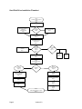
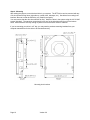
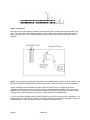
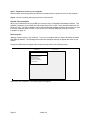
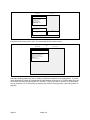
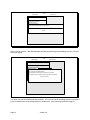
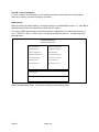
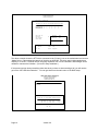
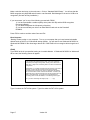
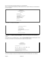
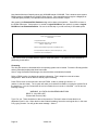
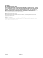
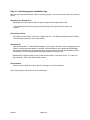
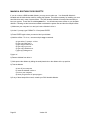
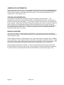
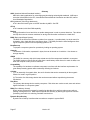
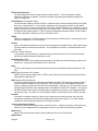
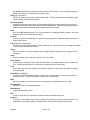
Installation Guide
DESKSTAR 14GXP
&
DESKSTAR 16GP
Models
DTTA-350320
DTTA-350430
DTTA-350640
DTTA-350840
DTTA-351010
DTTA-351290
DTTA-351680
Page 1
DTTA-371010
DTTA-371290
DTTA-371440
Version 3.0
Table of Contents
Technical Support . . . . . . . . . . . . . . . . . . . . . . . . . . . . . . . . . . . . . . . . . . . . . . . . . . . . .
Hard Disk Drive Installation Flowchart . . . . . . . . . . . . . . . . . . . . . . . . . . . . . . . . .
Hard Disk Drive Handling Guide . . . . . . . . . . . . . . . . . . . . . . . . . . . . . . . . . . . . . . . .
Installation Checklist . . . . . . . . . . . . . . . . . . . . . . . . . . . . . . . . . . . . . . . . . . . . . . . . . . .
Installation Kit . . . . . . . . . . . . . . . . . . . . . . . . . . . . . . . . . . . . . . . . . . . . . . . . . . . . . . . . .
Hardware Description . . . . . . . . . . . . . . . . . . . . . . . . . . . . . . . . . . . . . . . . . . . . . . . . . .
Installation . . . . . . . . . . . . . . . . . . . . . . . . . . . . . . . . . . . . . . . . . . . . . . . . . . . . . . . . . . . . .
Opening your computer . . . . . . . . . . . . . . . . . . . . . . . . . . . . . . . . . . . . . . . . . . . . . . . .
Unpackaging your hard drive . . . . . . . . . . . . . . . . . . . . . . . . . . . . . . . . . . . . . . . . . . .
Jumper Settings . . . . . . . . . . . . . . . . . . . . . . . . . . . . . . . . . . . . . . . . . . . . . . . . . . . . . . .
Mounting . . . . . . . . . . . . . . . . . . . . . . . . . . . . . . . . . . . . . . . . . . . . . . . . . . . . . . . . . . . . . .
Connectors . . . . . . . . . . . . . . . . . . . . . . . . . . . . . . . . . . . . . . . . . . . . . . . . . . . . . . . . . . . .
Easy Installation . . . . . . . . . . . . . . . . . . . . . . . . . . . . . . . . . . . . . . . . . . . . . . . . . . . . . . .
Custom Installation . . . . . . . . . . . . . . . . . . . . . . . . . . . . . . . . . . . . . . . . . . . . . . . . . . . .
BIOS Settings . . . . . . . . . . . . . . . . . . . . . . . . . . . . . . . . . . . . . . . . . . . . . . . . . . . . . . . . . .
FDISK . . . . . . . . . . . . . . . . . . . . . . . . . . . . . . . . . . . . . . . . . . . . . . . . . . . . . . . . . . . . . . . . .
Formatting . . . . . . . . . . . . . . . . . . . . . . . . . . . . . . . . . . . . . . . . . . . . . . . . . . . . . . . . . . . . .
File Systems . . . . . . . . . . . . . . . . . . . . . . . . . . . . . . . . . . . . . . . . . . . . . . . . . . . . . . . . . . .
Operating system installation tips . . . . . . . . . . . . . . . . . . . . . . . . . . . . . . . . . . . . . . .
Technical Support . . . . . . . . . . . . . . . . . . . . . . . . . . . . . . . . . . . . . . . . . . . . . . . . . . . . .
Automated Fax Back Service . . . . . . . . . . . . . . . . . . . . . . . . . . . . . . . . . . . . . . . . . . .
Making a Bootable DOS Diskette . . . . . . . . . . . . . . . . . . . . . . . . . . . . . . . . . . . . . . .
Jumper Block Information . . . . . . . . . . . . . . . . . . . . . . . . . . . . . . . . . . . . . . . . . . . . . .
Controller Information . . . . . . . . . . . . . . . . . . . . . . . . . . . . . . . . . . . . . . . . . . . . . . . . . .
Backup & Restore . . . . . . . . . . . . . . . . . . . . . . . . . . . . . . . . . . . . . . . . . . . . . . . . . . . . .
Utilities . . . . . . . . . . . . . . . . . . . . . . . . . . . . . . . . . . . . . . . . . . . . . . . . . . . . . . . . . . . . . . . .
Drive Copy . . . . . . . . . . . . . . . . . . . . . . . . . . . . . . . . . . . . . . . . . . . . . . . . . . . . . . . . . . . .
Compatibility Matrix . . . . . . . . . . . . . . . . . . . . . . . . . . . . . . . . . . . . . . . . . . . . . . . . . . . .
Glossary . . . . . . . . . . . . . . . . . . . . . . . . . . . . . . . . . . . . . . . . . . . . . . . . . . . . . . . . . . . . . . .
Technical Support
http://www.ibm.com/harddrive
888.426.5214
Page 2
Version 3.0
Page 2
Page 3
Page 5
Page 6
Page 7
Page 7
Page 8
Page 8
Page 8
Page 8
Page 10
Page 11
Page 12
Page 15
Page 15
Page 17
Page 19
Page 20
Page 21
Page 22
Page 22
Page 23
Page 24
Page 24
Page 24
Page 25
Page 25
Page 26
Page 27
Hard Disk Drive Installation Flowchart
Step 1
Assemble needed equipment
Page 6
Step 2
Remove cover of your computer
Page 8
Set jumpers for Master or
Standalone
(Shipping Default)
Page 8
Step 3
Set jumpers
Page 8
Set jumpers for Slave
Page 8
Step 4
Mount drive securely
Page 10
Step 5
Connect IDE and power
cables to drive
Page 11
Add-on Ultra DMA
Controller
Page 11
Step 6
Connect IDE
cable to
computer
Page 11
On board IDE
Ports
Page 11
Primary
Port
Page 11
Step 7
Replace cover on computer
Page 12
Step 8
Replace system cables
Page 12
Step 9a
Easy Install
Page 12
Installation
Page 12
Step 9b
Custom Install
Page 15
Check BIOS settings for full
capacity
Page 15
Boot from Ontrack® Disk
Manager Diskette
Page 12
Boot from bootable diskette
Page 17
Select Easy Disk Installation
Page 12
FDISK
Page 17
Complete Installation
Page 13
Format
Page 19
Step 10
Install Operating System if required
Page 21
Page 3
Version 3.0
Secondary
Port
Page 11
HARDWARE INSTALLATION AND DRIVE PREPARATION MANUAL
FOR IBM HARD DISK DRIVES
This manual has been prepared to help you install your IBM Deskstar 14GXP or Deskstar 16GP hard drive
in most computer systems. If you feel uncomfortable installing this drive yourself, take it to a qualified
installer.
International Business Machines Corporation provides this publication "AS IS" without warranty of any kind,
either express or implied, including, but not limited to, the implied warranties of merchantability or fitness for
a particular purpose. Some states do not allow disclaimers of express or implied warranties in certain
transactions, therefore, this statement may not apply to you.
This publication could include technical inaccuracies or typographical errors. Product data and specifications are subject to change without notice. Changes are periodically made to the information herein;
these changes will be incorporated in new editions of the publication. IBM may make improvements and/or
changes in the product(s) and/or the program(s) described in this publication at any time.
It is possible that this publication may contain reference to, or information about, IBM products (machines
and programs), programming, or services that are not announced in your country. Such references or
information must not be construed to mean that IBM intends to make available such IBM products, programming, or services in your country.
Product description data contained herein represents IBM’s design objectives and is provided for comparison among IBM products; actual results may vary based on a variety of factors. The product data
contained herein does not constitute a warranty. Questions regarding IBM warranty terms or the methodology used to derive data should be referred to an IBM representative.
Technical information about IBM hard disk drive products can be found on the web at
http://www.ibm.com/harddrive or by calling IBM hard disk drive technical support at 888.426.5214
©Copyright International Business Machines Corporation 1998. All rights reserved. Note to US
Government Users - Documentation related to restricted rights - Use, duplication or disclosure is subject to
restrictions set forth in GSA ADP Schedule Contract with IBM Corp.
IBM is a registered trademark of the International Business Machines Corporation. The following are also
trademarks or registered trademarks of the International Business Machines Corporations in the United
States, other countries, or both: Deskstar, OS/2, and Surepath. Any other products or trademarks are the
property of their respective owners.
Page 4
Version 3.0
Before you begin, please read the following on handling your disk drive:
HARD DISK DRIVE HANDLING GUIDE
These notes are designed to provide a simple overview of the need to be cautious when
handling a disk drive.
Disk drives can be easily damaged either by electrical static shock or by rough handling. In order to
minimize the risks it is essential that any disk drive be handled on a cushioned surface (which is
electrostatically safe). Many such static safe mats are available, examples are 3M's 8210 table mat or
3M's "First Touch" computer pad. Great care should be taken when handling disk drives - treat them like
fragile eggs. Do not bump them against any object. When attaching brackets or mounting the drive in the
computer, be very careful. It is VERY EASY to introduce shocks which exceed the specification.
Please note that the robustness for each disk drive to withstand electrical or mechanical shock is different,
depending on its design. The hard disk drive technical support center can advise you on the suitability of
your Deskstar drive for a specific application.
Damage might not be immediately evident and may cause the drive to fail months later.
Page 5
Version 3.0
Step 1: Installation Checklist
To install the Deskstar drive you may need the following depending on your computer:
1) __ The installation kit that came with your Deskstar drive containing 4 mounting screws,
IDE cable, Ontrack® Disk Manager and any related publications. Save the box the
drive came in.
2) __ The documentation that came with your computer or storage enclosure.
3) __ A small, flat-blade screwdriver.
4) __ An IDE controller, which is either built in or an adapter inside your computer. Have
documentation readily available for your IDE controller also.
5) __ Mounting brackets, if required for your computer. Contact your place of purchase if you
are unsure if mounting brackets are required.
6) __ A bootable DOS diskette. (If one is not available to you, see instructions for making a
bootable DOS diskette in the appendix.) The Ontrack® diskette is bootable.
7).__ If you are replacing an older internal drive with the new Deskstar drive and want to copy all of the
files from the older drive to your new one, you may need additional software. (See the section on
Drive Copy on page 25 for information.)
Continue installation with the following procedures:
1) __ Backup your existing drive to avoid any loss of data during installation.(see Backup & Restore on
page 24) After completing backup, shut down as normal.
2) __ Unplug your system from the electrical outlet.
3) __ Establish a common voltage between you and the hard drive. Touch an unpainted metal
surface on the outside of your system with your bare hands and the hard drive in it’s
anti-static bag simultaneously. Avoid excessive movement until the drive has been mounted.
4) __ DO NOT LOW-LEVEL FORMAT YOUR IDE DRIVE! IDE drives are low-level formatted by the
manufacturer and reformatting may cause permanent damage to yourdrive and your system.
(See Utilities on page 25)
5) __ Record the following information:
Drive Model ________________
Drive P/N __________________
Serial # ____________________
Date of Purchase_________________
Place of Purchase_________________
If you currently have a hard drive in your system you may want to record the CMOS settings. This
information is in your BIOS setup. You can enter your BIOS setup by pressing the key sequence for your
system while booting. (See BIOS on page 15)
Cylinders _______________________
Sectors/Track_____________________
Heads __________________________
Landing Zone _____________________
Write Pre Comp (if you have this category) __________________
Page 6
Version 3.0
Installation Kit
The DTTA model drives come complete with 4 screws for mounting, an IDE cable and an installation guide.
It also comes with Ontrack® Disk Manager and any related publications.
Screwdriver
Hard Drive
Installation
Guide
Installation
Guide
Jumpers
Ontrack
IDE Cable
Screws
Disk Manager
Hardware Description
The Deskstar 16GP and 14GXP family has an advanced Ultra ATA interface and supports transfer rates of
up to 33.3 MB/sec. To take advantage of the higher transfer rate of 33.3 MB/sec, your computer will need
to have a controller that supports the Ultra ATA interface. If you have an older interface such as Multi-word
DMA Mode-2 or PIO Mode-4, the drive will work, but will be limited in data transfer speed due to the lower
speed of your controller. If you have a slower controller, you may choose to purchase a UltraDMA
controller card (fits into one of the available slots in your computer) to take advantage of Deskstar’s
33.3MB/sec data transfer rate. To determine if your current controller card is Ultra DMA, see the
documentation that came with your system or contact the computer manufacturer for information.
Whether you use your desktop computer for audio and video editing, computer-aided design and
manufacturing (CAD/CAM), 3D graphics, animation and photo manipulation, web page design, or data
mining and data warehousing - advanced desktop applications such as these demand an advanced data
storage solution. These drives are 3.5" drives designed to work in Entry Servers, Entry Workstations and
Desktop personal computers. The Deskstar 16GP is available in capacities of 3.2, 4.3, 6.4, 8.4, 10.1, 12.9
and 16.8 GB running at 5400 RPM. The Deskstar 14GXP is available in capacities of 10.1, 12.9 and 14.4
GB and runs at 7200 RPM. The Deskstar 14GXP and Deskstar 16GP families are designed to work with
MMX systems. Compatibility listings are included in the appendix.
Page 7
Version 3.0
Step 2: Installation
Opening your computer
1. Turn the system off.
2. Unplug the power cord from the wall outlet.
3. Remove all cables from the back of your computer, labeling them if necessary.
4. Remove the cover from your computer. (Consult your user's guide for instructions if needed.)
Unpackaging your hard drive
1. Remove the drive from the anti-static package that it was shipped in.
2. Handle the drive by the sides only.
3. Do not touch the main computer chip board.
4. Do not drop. A drop from only 1/4 inch could permanently damage your hard drive.
5. If available, use an ESD (Electronic Static Discharge) wrist strap while handling your drive.
6. Place the drive carefully on a static free area.
Step 3: Jumper Settings
The jumper settings are found on the hard drive next to the interface connector. (See diagram on page 9)
They are physical settings that you need to change for different uses of your hard drive. If your drive will
be used as a single drive or as a boot drive, no changes are required. The drive is shipped with jumpers
set to Master. If you wish your drive to be the Master drive, skip to Mounting on page 10.
Decide how you want to set up your drive. Will it be the only drive in the system? Will it be in a system
that has an existing drive?
Single drive - Master setting
Use this setting if you are replacing your old drive with the new Deskstar drive and you
will not be using your old drive.
Put a jumper on pins A-B & G-H to make this drive the only drive in your system.
(Shipping default is 'Master' setting - 16 heads)
Second drive - Master setting (boot drive)
Put a jumper on pins A-B & G-H.
(Note: If your BIOS setup does not detect the slave drive, you may need to use the
SLAVE present setting by placing a jumper on pins E-F & G-H.)
Second drive - Slave setting
Use this setting if you want to retain your old drive as the boot drive and have the new
drive available for program and data storage.
Put the jumper on pins A-B & C-D.
Cable Select This setting should be used if your system uses special “cable select” cables.
Page 8
Version 3.0
Interface Connector
Power Connector
Jumper Block
Jumper Block Location
Some BIOSs have a limitation when translating the Cylinder, Head, and Sector information resulting in an
inability to correctly detect the larger capacity drives. Most systems don’t have this limitation but if your
BIOS is reporting the capacity incorrectly, use the 15 logical head settings rather than the 16 logical heads.
Settings are shown below.
Interface
Connector
I
G
E
C
A
H
F
D
B
Power
Connector
16 Logical Head
Device 0 (Master)
(Shipping default)
Device 1 (Slave)
I
I
I
15 Logical Head
G
E
C
A
H
F
D
B
G
E
C
A
H
F
D
B
G
E
C
A
H
F
D
B
G
E
C
A
H
F
D
B
I
I
I
G
E
C
A
H
F
D
B
G
E
C
A
H
F
D
B
G
E
C
A
H
F
D
B
G
E
C
A
H
F
D
B
Cable Select
Device 0
(Slave present)
Device 1 (Slave)
Cable Select
I
I
Jumper settings
Page 9
Device 0 (Master)
(Shipping default)
Version 3.0
Device 0
(Slave present)
Step 4: Mounting
After setting the jumpers, mount the hard drive in your system. The DTTA drive can be mounted with any
of its six surfaces facing down (right side up, upside down, sideways, etc.). See below for mounting hole
locations. Be sure to treat the disk drive very carefully and gently.
You must ensure that the drive has sufficient air flow. Mount the drive in the system using the 4 6-32 UNC
screws (included). The maximum screw length is 3.5 mm for the side holes and 6 mm for the bottom
holes. Mount the drive securely enough to prevent it from excessive motion or vibration.
If you are mounting your drive in a 5” bay, you may need to purchase mounting brackets from your
computer manufacturer for the drive to be mounted securely.
Mounting hole locations
Page 10
Version 3.0
Step 5: Connectors
After the drive has been carefully mounted, connect the IDE cable (included) and the power cable to the
drive. If you are using a cable already installed in your computer, ensure that the cable length does not
exceed 18 inches (45.7 cm). (Note that the IDE connector and power connector are keyed for proper
insertion)
Step 6: Plug the cable into either the onboard port or the UDMA controller that you may have added. The
figure below shows the possible location of the onboard ports. Each port is marked on the motherboard.
To take advantage of the Ultra DMA 33 transfer rates that the DTTA drive is capable of, an add-on
UDMA33 controller may be used if your system does not already support Ultra DMA. There are several
manufacturers to choose from. This card will be plugged into one of the expansion slots. The drive will be
connected to this card rather than to the primary or secondary slot in the motherboard.
If you are not using a UDMA33 card, plug the IDE cable into one of the two slots on the motherboard. It is
suggested that you connect to the “primary” slot for the first two drives and into the “secondary” slot for the
second two drives. These may be hard drives, CD-ROMS or removable drives.
Page 11
Version 3.0
Step 7: Replace the cover on your computer
With the cables connected properly and the drive mounted securely, replace the cover on the computer.
Step 8: Connect all cables and plug the power cord into the wall.
Step 9A: Easy Installation
When you purchased this drive from IBM, you received a copy of Ontrack® Disk Manager software. This
software is necessary if your BIOS does not support drives over 8.4 GB. There are also limitations at 4.2
GB and 2.1 GB. This easy installation will use the Disk Manager diskette to partition and format your drive.
If the easy installation does not work, or you choose not to use Disk Manager, continue to Custom
Installation on page 15.
Boot Computer
“Booting” means turning on your computer. Turn on your computer after you have inserted the Ontrack®
Disk Manager diskette. The following screen shots are examples and may not appear the same on your
system.
A large blue IBM screen will appear after several seconds and then the following screen.
IBM
Disk Manager
Version 9.42.02
Select an Installation Option
(E)asy Disk Installation
(A)dvanced Disk Installation
(M)aintenance Menu
(U)pgrade Disk Manager
(V)iew/Pring Online Manual
Exit Disk Manager
Select Easy Disk Installation. The following screen will appear.
Page 12
Version 3.0
IBM
Disk Manager
Version 9.42.02
Select an Installation Option
(E)asy Disk Installation
(A)dvanced Disk Installation
(M)aintenance Menu
(U)pgrade Disk Manager
(V)iew/Pring Online Manual
Exit Disk Manager
Disk Manager found 1 drive.
Is the drive list correct?
Drive List
(Y)ES
(N)O
1) IBM-DTTA-351680
If the drive list is correct, select (Y)es. The screen that follows is shown below.
IBM
Disk Manager
Version 9.42.02
Select an Installation Option
Select the operating system you
are using or plan to install.
(E)asy Disk Installation
(A)dvanced Disk Installation
Windows 95 (or OSR1)
(M)aintenance
Menu 95 OSR2)
Windows 98 (or Windows
(U)pgrade
Windows NTDisk
3.51 Manager
(or earlier)
Windows NT 4.0
(or later)
or OS2
(V)iew/Pring
Online
Manual
DOS/Windows
3.1x
Exit Disk Manager
Other
Return to previous menu
Select the operating system you plan to install (or already have installed on an existing drive). If you are
using Windows® 95 version B or Windows® 98, Disk Manager will create a FAT 32 file system which will
let you have the entire drive partitioned into 1 partition. If you do not wish to use the FAT 32 file system,
you can select the FAT 16 file system by choosing (N)o from the following screen. (See File Systems on
page 20)
Page 13
Version 3.0
IBM
Disk Manager
Version 9.42.02
Select an Installation Option
(E)asy Disk Installation
(A)dvanced Disk Installation
(M)aintenance Menu
(U)pgrade Disk Manager
Disk
Manager
canManual
format your hard drive using the 32-Bit FAT file system.
(V)iew/Pring
Online
Would
you
like to install thi sdrive using FAT32?
Exit Disk
Manager
(Y)ES
(N)O
Select (Y)es to continue. After Disk Manager has finished partitioning and formatting your drive, the next
screen will appear.
IBM
Disk Manager
Version 9.42.02
(E)asy Disk Installation
(A)dvanced Disk Installation
(M)aintenance Menu
Disk Manager Status
(U
(V
E Disk 1 has been successfully installed!
The DOS partitions that have been created are now formatted.
Each partition will be accessible as a logical drive letter after rebooting
(Any key to continue)
Your drive has now been partitioned and formatted. You can now load an operating system on the drive if
you don’t already have an operating system on another drive. See Operating Systems on page 21.
Page 14
Version 3.0
Step 9B: Custom Installation
If you do not wish to use Ontrack® or if your system will install the drive without the overlay program,
continue by checking your drive’s settings in your BIOS.
BIOS Settings
Begin by checking the CMOS settings. The example below is an Award© BIOS version 4.51. Other BIOSs
should be similar. Follow the instructions provided with your system.
To enter the CMOS setup screen press the key sequence designated by your system manufacturer (i.e.
<F1>; <DELETE> <ESC>; <CTRL> <ALT> <S>) during the initial boot process. This will bring up the
following screen.
ROM PC/ISA BIOS (2A5IHROB)
STANDARD CMOS SETUP
AWARD SOFTWARE, INC.
STANDARD CMOS SETUP
INTEGRATED PERIPHERALS
BIOS FEATURES SETUP
SUPERVISOR PASSWORD
CHIPSET FEATURES SETUP
USER PASSWORD
POWER MANAGEMENT SETUP
IDE HDD AUTO DETECTION
PNP/PCI CONFIGURATION
HDD LOW LEVEL FORMAT
LOAD BIOS DEFAULTS
SAVE & EXIT SETUP
LOAD SETUP DEFAULTS
EXIT WITHOUT SAVING
: Select Item
F10 Save & Exit Setup
(Shift)F2: Change Color
Time, Date, Hard Disk Type...
Select “Standard CMOS Setup”. This selection will bring up the following screen.
Page 15
Version 3.0
ROM PC/ISA BIOS (2A59IR09)
STANDARD CMOS SETUP
AWARD SOFTWARE, INC.
Date (mm:dd:yy) : Tue, May 27 1998
Time (hh:mm:ss) : 18:12:49
HARD DISKS TYPE SIZE CYLS HEAD PRECOMP LANDZ SECTOR MODE
Primary Master : User 8455
Primary Slave : None 0
Secondary Mst : None 0
Secondary Slv : None 0
16383
0
0
0
16
0
0
0
Drive A : 1.44M, 3.5 in.
Drive B : None
65535
0
0
0
16382
0
0
0
63
0
0
0
Base Memory:
Extended Memory:
Other Memory:
Video : EGA/VGA
Halt On: All Errors
AUTO
-------------------
640K
64512K
384K
Total Memory: 65536K
: Select Item
PU/PD/+/- : Modify
F1 : Help
(Shift) F2
: Change Color
The above example shows the DTTA drive connected to the “Primary” port on the motherboard and set as a
“Master” drive. It also shows the capacity of the drive as 8455 MB. The drive used in this example has a
capacity of 16.8 GB. This BIOS will not recognize capacities over 8.4 GB. Ontrack®’s Disk Manger will be
needed to overcome the limitation. (Go back to Easy Installation.)
If the previous screen shows something other than what you have or shows nothing at all, you will need to
go into the “IDE HDD Auto Detection”. You can get there from the main menu of the BIOS setup.
IDE HDD Auto Detection
ROM PC/ISA BIOS (2A5IHROB)
STANDARD CMOS SETUP
AWARD SOFTWARE, INC.
HARD DISKS TYPE SIZE CYLS HEAD PRECOMP LANDS SECTOR MODE
Primary Master :
Select Primary Slave
Option (N = Skip) : N
OPTIONS SIZE CYLS HEAD PRECOMP LANDZ SECTOR MODE
2(Y)
1
3
8447
8455
8455
1027 255
16382
16
8191
63
0
65535
65535
16382
16382
16382
63 LBA
63 Normal
63 Large
Note: Some OSes (like SCO-UNIX) must use "NORMAL" for installation
ESC : Skip
Page 16
Version 3.0
Make a selection and return to the main menu. Click on “Standard CMOS Setup”. You will see that the
BIOS recognizes only 8455 MB and will need to use Ontrack® Disk Manager for the entire 16 GB to be
recognized. (Go back to Easy Installation.)
If you can answer “yes” to any of the following, proceed with FDISK.
1) You have purchased a smaller capacity drive (under 8.4 GB) and the BIOS recognizes
the correct capacity;
2) Your BIOS recognizes the full capacity of the drive;
3) You have connected your drive to an Ultra DMA 33 card such as the Promise©
UDMA33;
Press ESC to continue and then select Save and Exit.
Boot Computer
“Booting” means turning on your computer. Turn on your computer after you have inserted a bootable
diskette such as DOS or your Windows® startup diskette. You will need to use Windows® 95 OS/R2 or
Windows® 98 FDISK for the drives larger than 8 GB. DOS FDISK will not recognize drives larger than 8
GB.
FDISK
Type FDISK at the A:\ prompt after booting to a bootable diskette. If Windows® 95 OS/R2 or Windows®
98 are used, the following screen will appear.
Your computer has a disk larger than 512 MB. This version of Windows
includes imporved support for large disks, resulting in more efficient use of
disk space on large drives, and allowing disks over 2 GB to be formatted as
a single drive.
IMPORTANT: If you enable large disk support and create any new drives on
this disk, you will not be able to access the new drive(s) using other
operating systems, including some versions of Windows 95 and Windows
NT, as well as earlier versions of Windows and MS-DOS. In addition, disk
utilities that were not designed explicitly for the FAT32 file system will not be
able to work with this disk. If you need to access this disk with other
operating systems or older disk utilities, do not enable large drive support.
Do you wish to enable large disk support (Y/N)...............? [N]
Type Y to select the FAT 32 file system. Type N to select the FAT 16 file system.
Page 17
Version 3.0
Next you will see the screen below allowing you to create partitions.
Note: You will only have 5 options if you have more than 1 drive. Option 5 allows you to select the drive
you wish to partition.
PC DOS Version 7.0
Fixed Disk Setup Program
Copyright IBM Corporation 1983-1994
FDISK Options
Current fixed disk drive:
1
Choose one of the following:
1. Create DOS partition or Logical DOS Drive
2. Set active partition
3. Delete partition or Logical DOS Drive
4. Display partition information
5. Change current fixed disk drive
Enter choice:[1]
Press ESC to exit FDISK
Select option 1 to create the DOS partition.
Create DOS Partition or Logical DOS Drive
Choose one of the following:
1. Create Primary DOS Partition
2. Create Extended DOS Partition
3. Create Logical DOS Drive(s) in the Extended DOS partition.
Enter choice: [3]
Press ESC to return to FDISK Options
Select option 1 to Create a Primary DOS Partition. If this is to be the boot drive, set this partition to
“Active”.
Press ESC to return to the FDISK options. Create an Extended DOS Partition by selecting option 1 from
the main menu and option 2 from the second menu. (Both menus shown above.)
PC DOS Version 7.0
Fixed Disk Setup Program
Copyright IBM Corporation 1983-1994
Create Extended DOS Partition
Current fixed disk drive: 2
Partition Status
D:1
A
Type
Volume Label Mbytes
PRI DOS
2047
System
UNKOWN
Usage
66%
Total disk space is 3095 Mbytes (1 Mbyte = 1048576 bytes)
Maximum space available for partition is 1047 Mbytes (34%)
Enter partition size in mbytes or percent of disk space (%) to create an
Extended DOS Partition.........[1047]
The previous example is based on the Deskstar 16GP model DTTA-350320 which is a 3.2 GB drive.
Page 18
Version 3.0
Note that the Maximum Capacity shows only 3099 MB instead of 3240 MB. This is because some system
BIOSs recognize a Megabyte as 1,048,576 bytes (binary). Drive manufacturers recognize a Megabyte as
1,000,000 bytes (decimal). The capacities are the same in actual number of bytes.
After creating the Extended DOS Partition assign a drive letter to that partition. Press ESC to return to
the FDISK main menu. Select option 1 to create a Logical DOS Drive, then option 3 to create a Logical
DOS Drive in an Extended Partition. Be sure to do this step or you will have only 2 GB usable space.
Create Logical DOS Drive(s) in the Extended
DOS Partition
No logical drives defined
Total Extended DOS Partition size is 1047 Mbytes
(1 MByte = 1048576 bytes)
Maximum space available for logical drive is 1047Mbytes (100%)
Enter logical drive size in Mbytes or percent of disk space (%).....[1047]
Press ESC to return to FDISK Options
Press ESC to return to FDISK and ESC again to restart the system. The system must be restarted for
partitioning to take effect.
Formatting
The drive will need to be formatted before an operating system can be loaded. Format the Primary partition
and any Extended partitions that have been made.
Note: If using Ontrack®’s Disk Manager, the drive has been automatically formatted.
Refer to FDISK, option 4 to display the partition information. This is helpful to review drive letter
assignments. Note the drive letters to ensure proper formatting.
Press ESC to return to the main menu and exit FDISK. At the A:\ prompt type format x: /s
(where x is the drive letter). The /s option will make your hard drive bootable by copying the system files to
the hard drive. If you do not want this drive to be bootable, do not use the /s command. You will see the
following warning:
WARNING: ALL DATA ON NON-REMOVABLE DISK
DRIVE C: WILL BE LOST!
Proceed with Format (Y/N)?
Type Y for yes. There should be no data on the new drive. The time it takes to format the drive is
dependent upon it’s size. When the drive has finished formatting, format the next logical drive, in this case
D: by typing format d: You will get the same message. Select Y.
Page 19
Version 3.0
File Systems
FAT 16/FAT 32(File Allocation Table)
The file allocation table is specific sectors in a hard drive that contain an address book for the different
files on a hard disk drive. In other words, it keeps track of the physical location on each platter where files
are stored. There are usually two FATs (kept in different locations) on a hard drive. One is kept as a
backup in case data corruption occurs on the other FAT. FAT32 is used in the Windows® 95 &
Windows® 98 operating system. FAT32 receives its designation because it allows 32 bits of data to be
read as opposed to 16 bits at a time as in the older FAT16.
HPFS (High Performance File System)
HPFS is the file system used by OS/2. HPFS is more efficient, give better performance and resists
fragmentation better that FAT.
NTFS (NT File System)
NTFS is an advanced file system used by Windows® NT. NTFS provides built-in compression, large
partition support and better performance.
Page 20
Version 3.0
Step 10: Operating system installation tips
After the drive has been formatted, install an operating system. You may encounter some of the following
issues.
Windows® 95 / Windows® 98
Windows® 95 must be version OSR2 or later to support a drive larger than 8.4 GB.
In Windows® 98 the system may hang-up when trying to self-restart. Reset or power cycle
required.
OS/2 and OS/2 Warp
OS/2 Warp 4.0 with Fixpack 5 only sees 7.9GB of the drive. The OS/2 development team is working
on this problem and plans to have a fix available.
Windows® NT
With Windows® NT 5.0, Ontrack® Disk Manager is not required. However, when creating partitions, a
reboot is required after each partition is created. After the partitions are created with Disk Manager,
they must be formatted from a command prompt. Some systems require that the installation drive for
Windows® NT 5.0 must be partitioned and formatted before installing NT 5.0
Windows® NT 4.0(service pack 3) may not see the full capacity of the larger drives. To fix this, you
may download a “hotfix” from Microsoft’s® web site.
Novell Netware
Novell only sees 7.9GB of the drive. Novell is working on a fix to this limitation.
Note: Overclocking of the PCI bus is not recommended.
Page 21
Version 3.0
Technical Support
Before calling technical support make sure you have your drive part number, serial number and system
information.
Contact technical support via:
Web
Voice
Fax
e-mail
www.ibm.com/harddrive
888.426.5214 or 507.253.4110
507.253.4111
[email protected]
Support is also available in Singapore at:
(65) 840.9292
Automated Fax Back Service
U.S.A. 408.256.5218
Singapore
800.1100.383
England0800.96.6948
Germany
0130.82.6089
France
0800.902229
Italy
167.875148
Page 22
Version 3.0
MAKING A BOOTABLE DOS DISKETTE
If you do not have a DOS bootable diskette, you may want to make one. Your Ontrack® diskette is
bootable and will eliminate the need for creating this diskette. This will be necessary for installing your new
hard disk drive and in case of system failure. The DOS bootable diskette will contain files necessary to
boot your system. These files are called system files. You will also want some utilities on your bootable
diskette. Following are the instructions needed to add both the system files and the other helpful utilities.
1) Make sure your computer is on and you insert a diskette in drive A.
2) At the C:\ prompt, type FORMAT A: /S and press ENTER
3) Press ENTER again unless you want to label your diskette.
4) Add the utilities. To do so, use some simple copy commands.
a) type at the C:\ prompt - cd dos
b) type copy fdisk.exe a:
c) type copy format.com a:
d) type copy sys.com a:
e) type copy chkdsk.exe a:
f) type copy debug.exe a:
5) type cd..
6) Remove diskette from drive A:
7) Write protect the diskette by sliding the small plastic tab on the diskette in the up position.
8) Test the diskette
a) turn off your computer
b) Insert the diskette in drive a
c) turn on your computer
d) when you get to the A:\ prompt type c:
9) If any of these steps did not work, remake your DOS bootable diskette.
Page 23
Version 3.0
JUMPER BLOCK INFORMATION
The jumper block is a block of pins located on the hard drive that when shorted with a shunt (jumper) will
make the drive behave in certain ways. The shunt is a small piece of plastic with metal inside that shorts
out the connection between 2 pins when placed over the pins. These can be purchased at any local
computer store. The pin pitch is 2 mm.
CONTROLLER INFORMATION
The examples in this guide have used IDE ports that are imbedded in the Motherboard. If your
motherboard is old and you would like Enhanced IDE or an ULTRA DMA 33 controller, you may want to
purchase a controller card (host adapter). You will need to install the controller into one of the empty slots
in your computer. Simply remove the screw holding the metal plate intact, insert the controller into the PCI,
EISA or ISA slot on the motherboard making sure that the metal plate from the controller fits into the
grooves allotted on the computer frame. Replace the screw and proceed by connecting the IDE cables to
the controller and then the hard drive. If you have any questions, refer to the installation manual that
should be enclosed with your controller.
BACKUP & RESTORE
One of the most common methods of backup is tape backup. Tape drives are available from IBM and
other major manufacturers. This method is preferred for overnight backups that run while your business is
closed or while you sleep.
Another method of backup is a removable drive. There are several brands of removable drives. IOMEGA
is one manufacturer. They manufacture the ZIP drive which is very popular and also the JAZ drive. These
drives can be used simply for backup and hooked up and removed at any time with very little trouble. This
is the preferred way to backup and restore when attaching new peripherals to your current setup.
DOS has a Backup and Restore command. To back up critical files (files that you do not want to lose)
from the directory your files are in type: backup. This will prompt you to add more diskettes as necessary.
In case of a failure, you will simply need to insert the first diskette of your backups and type: restore.
Page 24
Version 3.0
Utilities
Your Deskstar drive comes low-level formatted and free of defects. NOTE: DO NOT ATTEMPT TO LOW
LEVEL FORMAT AN IDE DRIVE. In the rare case where data needs to be removed from the drive, there
are 2 utilities available from the HDDTech FTP site at: http://index.storsys.ibm.com/hddtech
.
ZAP: Zap is a utility that will 'zap' your boot sector by writing 0's to the first 128 sectors of your drive.
WIPE: Wipe goes one step further and writes 0's to the entire drive.
These utilities should be sufficient to return your drive to factory shipped condition.
Drive Copy (Copy data from your old drive to your new drive)
If you are replacing an older smaller hard drive with the Deskstar drive, you may want to copy all your files
from the smaller drive to the new drive. There are several software programs available that copy one drive
to another.
Power Quest (www.powerquest.com/product/dc.index.html) Drive Copy 2.0. Supports all operating
systems, has mouse support, selective partitioning, selective sector copying, and automatically creates
new DOS reboot disk. Not limited by drive size.
Quarter Deck Systems (www.qdeck.com/qdeck/products/diskclone/indexreg.html) Disk Clone. Supports
all operating systems, has mouse support.
ITS Systems (www.itechs-systems.com/) Transfer EZ. For use only with Windows® 3.1 and Windows®
95.
Image Systems Solutions (www.img-systems.com/d2ddesc.htm) Drive to Drive. For use with all operating
systems, but limited to copying only drives with similar physical geometry.
FWB software (www.FWB.com/) Drive Up. For Windows® OS only. Came out in March of this year.
Page 25
Version 3.0
Compatibility Matrix
The Deskstar drives have been tested and proven to work with a wide variety of PCs, system boards.
operating Systems and BIOS versions. Following is a partial compatibility list.
SYSTEMS
Apple Performs 6400
AST Bravo MS 6266
AST Bravo MS 6300
Compaq XL 6150
DelI Dimension XPS
D300
Dell Optiplex GX Pro
Digital PC 5500
Gateway 2000 G6-266
Gateway 2000 GP6-233
Gateway 2000 P5-133
Gateway 2000 P5-200
HP Kayak XU
HP Pavilion
HP Vectra
IBM Systems
Micron Millenia XKU
Micron Powerdign XSU
NEC Direction SPL 268
NEC Powermate
NEC Valuestar
Sony VAIO
System Technology
GSSGUPS
SYSTEM BOARDS
ABIT IT5H
ABIT PX5
Acer AP5T
Aopen AP5T
Asus SP97V
Asus P2L97
Asus P55T2P4
Asus P55SP3AV
SYSTEM BOARDS
Asus TX97
Atrend ATC 612
ChainTech 6LTM
DFI 586ITX
DFI G5860 VPS
Elite P5TX
Elite P6LX
FIC KL-601 1
FIC PA-2006
FIC PA-2010
FIC PA-2012
Free P5F79
Gigabyte GA-586TX
Gigabyte GA-686LX
Intel Atlanta
Intel Lonetree
Intel Portland
Intel Tucson
Intel Venus
Microslar MS-5148
Microstar MS-5163
Mitac PH54OOTX
Mycomp AI6NL
Mycomp T15TT
Nex'r P5v580
QDI P6-440LX
Shuttle H0T569
Soyo SY-6KB
SuperMicro P6DKF
SuperMicro P5MMA
SuperMicro P6DLS
Tyan S1570
Tyan S1572
OPERATING SYSTEMS
MacOS 8
MS DOS v6.22
Novell Netware v3.12 & v4.1
OS/2 v4.0
PC DOS v6.3 & v7.0
SCO Open Desktop v3.0
SCO Open Server v5.0
SCO UNIX 3.2.4.2
SCO Unixware 2.1
Windows® NT Workstation
v3.51
Windows® NT v4.0 and NT
v5.0 (beta)
Windows® 95 (Including
FAT32)
Windows® 98 (beta 3)
BIOS
AMI 1.00.02
AMI 1.00.03
AMI 1.00.04
AMI 1.00.05
AMI 1.00.06
Aopen 1.50
Award v4.51 PG
Award Rev 1.9F
Award 09/09/97
BROT 1.00.10
Compaq Rev486w
HP GG.06.10
IBM Surepath
Phoenix vl.10A17
Phoenix v4.05
Phoenixv4 Rev 5.12
Phoenix v4.06.03A
Phoenix v4.06.070
Page 26
Version 3.0
Glossary
ANSI (American National Standards Institute)
ANSI is the lead organization for encouraging and developing technological standards. ANSI represents the United States in the IEC, International Electrotechnical Commission and the ISO, International Standards Organization.
ATA (Advanced Technology Attachment)
ATA is the official name given to the IDE interface by ANSI. See IDE.
ATA-4
ATA-3 standard, with Ultra DMA capability.
Backup
Storing information from a hard drive on another storage area in order to prevent data loss. Tape drives
and Zip drives are two common mediums for saving vital information contained on a hard drive.
BIOS (Basic Input/Output System)
The BIOS is the first level of software contained in a computer. It provides basic, low level control for
keyboards, video, hard disk drives, and floppy drives. The BIOS provides the initial intelligence allowing the computer system to find an operating system to run.
Boot/Boot-up
To prepare a computer system for operation by loading an operating system.
Capacity
The amount of information, expressed in bytes, that can be stored on a hard drive. Also known as
storage capacity.
CMOS
The CMOS is a memory chip which keeps a data record of the components installed in a computer.
The CMOS receives a minute flow of power from a small battery which allows it to retain its data, even
when the computer’s main power is turned off.
Compatibility
The capability of a hardware or software component to conform with the interface requirements of a
given data processing system without adversely affecting its functions.
Cylinder
(1) In an assembly of magnetic disks, the set of all tracks that can be accessed by all the magnetic
heads of a comb in a given position.
(2) The tracks of a disk storage device that can be accessed without repositioning the access
mechanism.
Disk Drive
The primary data storage device used by computers. Disk drives are used to record, store and retrieve
digital information in a computer system.
DMA (Direct Memory Access)
Direct memory access is a process for transferring data directly to and from main memory without
passing it through the CPU. DMA improves speed and efficiency by allowing the system to continue
processing even while it is retrieving new data from the drive.
Dynamic Drive Overlay
Dynamic Drive Overlay is software that overwrites a computer’s system BIOS.
Page 27
Version 3.0
Electrostatic Discharge
The rapid change in electrical energy caused by static electricity. This can damage or destroy
electronic equipment or hardware. Prevention consists of grounding oneself before handling any
electronic equipment.
FAT16/FAT32 (File Allocation Table)
The file allocation tables are specific sectors in a hard drive that contain an address book for the different files on a hard disk drive. In other words, it keeps track of the physical location on each platter
where files are stored. There are usually two FATs (kept in different locations) on a hard drive. One is
kept as a backup in case data corruption occurs on the other FAT. FAT32 is used in the Windows® 95
& Windows® 98 operating system. FAT32 receives its designation because it allows 32 bits of data to
be read as opposed to 16 bits at a time as in the older FAT16.
FDISK
FDISK is a program run in DOS that allows a user to partition a hard disk drive. Partitioning your hard
disk drive is essential for it to work properly.
Format
When a hard disk is formatted, the computer writes a magnetic track pattern onto a disk surface, specifying the locations of the tracks and sectors. This information must exist on a hard disk before it can
store data.
FTP (File Transfer Protocol)
In the Internet suite of protocols, an application layer protocol that uses TCP and Telnet services to
transfer bulk-data files between machines or hosts.
Hard Disk Drive (HDD)
A stand alone disk drive that reads and writes data on rigid disks and can be attached to a port on the
system unit. Synonymous with fixed disk drive, hard drive.
Head
The tiny electromagnetic coil and metal pole used to create and read back magnetic patterns on the
disk.
HPFS (High Performance File System)
HPFS is the file system used by OS/2. HPFS is more efficient, gives better performance and resists
fragmentation better that FAT.
IDE (Integrated Drive Electronics)
Also known as ATA (Advanced Technology Attachment) by ANSI. IDE technology was developed to
overcome CMOS limitations in older computers. IDE is used as one of the standard interfaces between a computer’s input/output devices and the motherboard. Although it can be used with other bus
standards the IDE interface was originally based on the IBM PC ISA16 bit bus standard. The nature of
the IDE interface allows for only two components to be attached to each bus; one designated master
and the other slave. The IDE bus is unterminated, therefore, an IDE cable cannot exceed 18 inches.
Interface
A hardware of software protocol (contained in the electronics of the disk controller and drive) that
manages the exchange of data between the hard disk drive and the computer. The most common
interfaces for small computer systems are ATA (IDE) and SCSI.
Jumpers and Jumper Settings
Jumpers are small pieces of plastic with a conductive center. Jumpers are used to connect pins on a
device to provide settings that are changeable by the user, but remain constant during operation.
Master Drive
Master refers to the primary device (usually a hard disk drive) in an ATA interface.
Motherboard
Page 28
Version 3.0
The Motherboard holds the computer's main processors and circuitry. It also contains the memory,
BIOS, interconnection circuitry and the expansion slots.
NTFS (NT File System)
NTFS is an advanced file system used by Windows NT. NTFS provides built-in compression, large
partition support and better performance.
Operating System
Software that controls the execution of programs and that may provide services such as resource
allocation, scheduling, input/output control, and data management. Although operating systems are
predominantly software, partial hardware implementations are possible.
OS/2
OS/2 is an IBM operating system. It is a fully preemptive, multitasking operating system. OS/2 also
supports HPFS, a very advanced file system.
Partition
A portion of a hard drive dedicated to a particular operating system or application and accessed as a
single logical volume.
PIO (Programmed input/output)
PIO is the original operating mode for most hard disk drives. PIO uses the CPU to manage the transfer
of data from the hard drive to memory.
Sector
On an ATA drive, the minimum segment of track length that the hard disk drive can assign to store
information.
Slave
Slave is the term given to the second device on an ATA cable.
Slave Present
Slave present is a setting on some hard disk drives that is to be used when the drive is a Master device. It allows the Slave device on the same bus adequate time to identify itself.
Track
One of the many concentric magnetic circle patterns written on a disk surface as a guide for storing
and reading data.
Ultra DMA (Ultra DMA/33)
A protocol for transferring data between a hard disk drive and the main memory without passing it
through the CPU. It allows transmission of data at up to 33.3 MB/sec.
Wipe
Wipe is a software utility that writes zeros to every sector on a hard disk drive up to 8 GB.
Windows® NT
Microsoft’s 32-bit server operating system.
Windows® 98
A Microsoft operating system.
Zap
A utility in which the first 128 sectors of a hard drive are overwritten with zeros.
Zip Drive
A Zip drive uses increased real density on floppy disk technology to increase storage capacity. Zip
diskettes have a storage capacity of 100 MB and therefore are an attractive backup option.
Page 29
Version 3.0
®
© International Business Machines Corporation 2000
www.ibm.com/harddrive
IBM Hard Disk Drive Technical Support Center
Dept. WCN
3605 Highway 52 North
Rochester, MN 55901
Telephone: 888.IBM.5214 or 507.253.4110
Fax: 507.253.DRIVE
E-mail: [email protected]
Singapore Technical Support Center
Telephone: 65.1.800.840.9292
E-mail: [email protected]
IBM Storage Systems Division
5600 Cottle Road
San Jose, CA 95193
www.ibm.com/storage
Printed in the United States of America
01-2000
All Rights Reserved
IBM is the registered trademark and Deskstar is a trademark of
International Business Machines Corporation. Microsoft,
Windows, and Windows NT are registered trademarks of
Microsoft Corporation.
Other company, product, and service names may be trademarks
or service marks of others.
Produced by the IBM Hard Disk Drive Technical Support Center.
This information is believed to be accurate, but is supplied
without guarantee. Document subject to change without notice.
Date: 04 January, 2000
Page 30
Version 3.0