1
OWNER’S MANUAL
1600 MODEL INSERT
US ENVIRONMENTAL PROTECTION
AGENCY PHASE II CERTIFIED WOOD
INSERT
OREGON DEPARTEMENT
ENVIRONMENTAL QUALITY
Verified and tested following
ULC S628, UL 907, UL 1482 Standards by:
Manufactured by : STOVE BUILDER INTERNATIONAL INC.
250, rue de Copenhague, Saint-Augustin-de-Desmaures (Quebec) G3A 2H3
Tel.: 418 878-3040
Fax: 418 878-3001
www.osburn-mfg.com
This manual is available for free download on the manufacturer’s web site. It is a copyrighted document. Re‐sale is strictly prohibited. The manufacturer may update this manual from time to time and cannot be responsible for problems, injuries, or damages arising out of the use of information contained in any manual obtained from unauthorized sources. READ AND KEEP THIS MANUAL FOR REFERENCE
Printed in Canada
45084A
30-01-2013
TABLE OF CONTENTS
TECHNICAL SPECIFICATIONS ......................................................................................... 4 INSTALLATION ................................................................................................................... 5 DOOR OVERLAY INSTALLATION ............................................................................................6 DOOR ADJUSTMENT ...................................................................................................................7 PRE-INSTALLATION REQUIREMENTS ....................................................................................8 MINIMUM MASONRY OPENING, CLEARANCES TO COMBUSTIBLES, AND FLOOR
PROTECTOR.................................................................................................................................10 VENTING REQUIREMENTS ......................................................................................................12 INSTALLATION INSTRUCTIONS .............................................................................................13 OPERATION ..................................................................................................................... 18 TESTING YOUR WOOD..............................................................................................................19 THE FIRST FIRES ........................................................................................................................19 IGNITION ......................................................................................................................................19 HEATING ......................................................................................................................................20 RELOADING.................................................................................................................................20 CREOSOTE FORMATION AND NEED FOR REMOVAL ........................................................21 ASH DISPOSAL ............................................................................................................................21 MAINTENANCE ................................................................................................................ 22 GLASS ...........................................................................................................................................22 GASKETING .................................................................................................................................22 PAINT ............................................................................................................................................22 BAFFLE INSTALLATION ...........................................................................................................23 SECONDARY AIR TUBE REPLACEMENT ..............................................................................24 OSBURN LIMITED LIFETIME WARRANTY...................................................................... 25 REGISTER YOU WARRANTY ONLINE
To receive full warranty coverage, you will need to
show evidence of the date you purchased your insert.
Keep your sales invoice. We also recommend that
you register your warranty online at
http://www.osburn-mfg.com/warrantyregistration.aspx
Registering your warranty online will help us track
rapidly the information we need on your insert.
2
INTRODUCTION
SBI INC., one of the most important wood stove and fireplace manufacturers in Canada,
congratulates you on your purchase and wishes to help you get maximum satisfaction
from your wood insert. In the pages that follow, we will give you advice on wood heating
and controlled combustion as well as technical specifications regarding installation,
operation and maintenance of the model you have chosen.
The instructions pertaining to the installation of your wood insert comply with ULC-S628
and UL-1482 standards.
Read this entire manual before you install and use your new insert. If this insert is
not properly installed, a house fire may result. To reduce the risk of fire, follow the
installation instructions. Failure to follow instructions may result in property
damage, bodily injury, or even death.
Consult your municipal building department or fire officials about restrictions and
installations requirements in your area and the need to obtain a permit.
Keep this instructions manual for future references.
CAUTIONS:
HOT WHILE
IN OPERATION. KEEP CHILDREN, CLOTHING AND FURNITURE AWAY. CONTACT MAY
CAUSE SKIN BURNS.
DO NOT USE CHEMICALS OR FLUIDS TO IGNITE THE FIRE.
DO NOT LEAVE THE INSERT UNATTENDED WHEN THE DOOR IS SLIGHTLY OPENED.
DO NOT BURN WASTES, FLAMMABLE FLUID SUCH AS GASOLINE, NAPHTHA OR MOTOR OIL.
DO NOT CONNECT TO ANY AIR DISTRIBUTION DUCT OR SYSTEM.
ALWAYS CLOSE THE DOOR AFTER THE IGNITION.
3
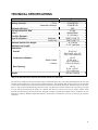
TECHNICAL SPECIFICATIONS
Combustible:
Recommended surface:
Heating Capacity* :
Optimum efficiency:
Average emissions, EPA:
Color :
Flue Pipe Diameter :
Type de cheminée :
E.P.A :
Seasoned cordwood:
Maximum:
Continuous: :
Minimum Vertical Flue Height :
Maximum Log Length :
Dimensions
Overall:
Combustion Chamber :
Width x Depth :
Volume :
Door Opening:
Weight:
Wood
Up to 1800 square feet
42,600 BTU/h
65,000 BTU/h
80%
4.4 g/h
Metallic Black
6’’ (152 mm)
2100°F (1150 °C)
1200°F (650 °C)
12’ (3,66 m)
17 1/2’’ (445 mm)
WxDxH
24 1/8 x 22 x 21 1/2"
(613 x 559 x 546 mm)
WxD
17 3/4 x 10 ’’
(451 x 254 mm)
1.85 ft3 (0,052 m3)
WxH
8 3/8 x 15 3/4’’
(213 x 400 mm)
360 lbs ( 164 Kg)
*Why is the BTU indicated on the EPA label smaller than the one advertised?
You will notice a difference between the BTU output as indicated on the unit’s white EPA label affixed to the glass and
the BTU as advertised on our web site and/or product literature. The maximum BTU output we advertise for this unit
is what will be obtained with a full load of seasoned cordwood inserted inside the firebox. The EPA output, on the other
hand, is what has been obtained during emissions testing. The EPA test procedure requires that a special type of wood
be used and positioned inside the firebox in a manner that does not represent the way the firebox volume would
normally be utilized using seasoned cordwood. The EPA test load is typically much smaller. Hence, the BTU as per the
EPA label is reduced. The BTU output that should be considered by a normal user is the one we advertise for seasoned
cordwood.
4
INSTALLATION
SAFETY NOTICE
IF THIS INSERT IS NOT PROPERLY INSTALLED, A HOUSE FIRE MAY RESULT. TO REDUCE THE RISK
OF FIRE, FOLLOW THE INSTALLATION INSTRUCTIONS. FAILURE TO FOLLOW INSTRUCTIONS MAY
RESULT IN PROPERTY DAMAGE, BODILY INJURY, OR EVEN DEATH.
CONSULT YOUR MUNICIPAL BUILDING DEPARTMENT OR FIRE OFFICIALS ABOUT RESTRICTIONS
AND INSTALLATIONS REQUIREMENTS IN YOUR AREA.
USE SMOKE DETECTORS IN THE ROOM WHERE YOUR INSERT IS INSTALLED.
KEEP FURNITURE AND DRAPES WELL AWAY FROM THE INSERT.
NEVER USE GASOLINE, GASOLINE-TYPE LANTERN FUEL, KEROSENE, CHARCOAL LIGHTER FLUID,
OR SIMILAR LIQUIDS TO START OR "FRESHEN UP" A FIRE. KEEP ALL SUCH LIQUIDS WELL AWAY
FROM THE INSERT.
IN THE EVENT OF A CHIMNEY FIRE, PUSH THE AIR CONTROL FULL CLOSED TO DEPRIVE THE FIRE
OF OXYGEN. CALL THE FIRE DEPARTMENT.
DO NOT CONNECT TO ANY AIR DISTRIBUTION DUCT OR SYSTEM.
A SOURCE OF FRESH AIR INTO THE ROOM OR SPACE HEATED SHALL BE PROVIDED WHEN
REQUIRED.
A WOOD INSERT MUST NEVER BE INSTALLED IN A HALLWAY OR NEAR A STAIRCASE, SINCE IT MAY
BLOCK THE WAY IN CASE OF FIRE OR FALL TO RESPECT REQUIRED CLEARANCES.
DO NOT INSTALL IN A SLEEPING ROOM.
5
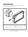
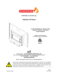
DOOR OVERLAY INSTALLATION
In order to complete the assembly of your Osburn 1600 wood insert, you need to install the door
overlay. See figure 1 below for installation instructions :
1- Position the overlay on the door frame and fix it in place from behind using the
4 screws.
Note: It is not necessary to remove the glass or any other component to install the overlay.
Figure 1 : Door overlay installation
6
DOOR ADJUSTMENT
In order for your insert to operate properly, the door should be adjusted periodically to
provide an air tight fit. To adjust:
Remove the lock pin (spring pin) by pulling and turning it using pliers ("wise grip")
Turn the handle counter clock wise one turn to increase pressure
Re-install the lock pin (spring pin) with a small hammer
Figure 2: Door Adjustment
7
PRE-INSTALLATION REQUIREMENTS
MASONRY & ZERO CLEARANCE REQUIREMENTS
The masonry fireplace must meet the minimum code requirements, or NFPA 21,1 or the
equivalent for a safe installation. Contact your local Building Inspector for requirements in
your area. An inspection of the fireplace should include the following:
1. CONDITION OF THE FIREPLACE AND CHIMNEY: Examine the masonry fireplace
and chimney prior to installation, to determine that they are free from cracks, loose
mortar, creosote deposits, blockage, or other signs of deterioration. If evidence of
deterioration is noted, the fireplace or chimney should be upgraded prior to installation.
2.
INSTALLATION INTO AN EXISTING FACTORY-BUILT ZERO-CLEARANCE
FIREPLACE: It is possible to install a wood insert into an existing factory-built zeroclearance fireplace. However, there currently exists no UL or ULC standard specific to
that type of installation. The first thing that must be verified is that the factory-built
zero clearance fireplace is listed (it must be certified by a competent certification body
such as Omni or Warnock Hersey). It must be suitable for use with solid fuel and
nothing in the owner’s manual must specifically prohibit the installation of a fireplace
insert. When in doubt, check with the fireplace manufacturer. The installation of the
zero-clearance fireplace MUST be thoroughly inspected by a professional in order to
ensure that it still meets the manufacturer’s specs and code conformity. The chimney
must be of at least 1" (25 mm) larger in diameter to accommodate a required
continuous stainless steel liner running from the flue collar to the top of the chimney
termination.
Never remove parts that serve to insulate the zero-clearance fireplace from
combustible material. Only readily detachable parts that are easily replaced, such as
damper parts, screens, and doors, are to be removed from the fireplace. These parts
must be stored nearby and available for retrofit if the insert is ever removed. Removal
of any parts which render the fireplace unfit for use with solid fuel requires the fireplace
to be permanently labelled by the installer as being no longer suitable for solid fuel
until the removed parts are replaced and the fireplace is restored to its original certified
condition. Furthermore, any air vents, grilles, or louvers that serve to create an air
circulation pattern around and outside the zero-clearance fireplace shall never be
removed.
3. HEARTH EXTENSION: Verify that there is a non-combustible hearth extending at
least 16" in front of the fireplace (18” for Canada, or 457 mm) and at least 8" (203mm)
to the side of the fireplace. Fireplaces without this hearth extension will not meet the
minimum requirements, and will require additional protection.
8
4. CHIMNEY CAPS: Mesh type chimney caps must have provision for regular cleaning,
or the mesh should be removed to eliminate the potential of plugging.
5. LINER: The chimney must have an acceptable masonry liner suitable for solid fuel,
otherwise a continuous stainless steel liner must be installed.
6. ADJACENT COMBUSTIBLES: The fireplace should be inspected to make sure that
there is adequate clearance to combustibles, both exposed combustibles to the top,
side, and front as well as concealed combustibles, in the chimney and mantle area.
Your local inspector should have information on whether older fireplaces are of
adequate construction.
7. OPENING SIZE: Refer to “Suitable Fireplace Dimensions” for suitable size fireplace
openings.
8. The flue pipe must not go through roof trussing, an attic, a wardrobe, a floor, a
combustible partition, or similar spaces.
9. A flue pipe crossing a combustible wall must have a minimum clearance of 18".
10. To reduce flue pipe clearances from combustible materials, contact your local safety
department.
9
MINIMUM MASONRY OPENING, CLEARANCES TO COMBUSTIBLES, AND
FLOOR PROTECTOR
10
MINIMUM MASONRY
OPENING
MAXIMUM
STANDARD
FACEPLATE
MAXIMUM
LARGE
FACEPLATE
F
22.125"
(562 mm)
29" (737 mm)
32" (813 mm)
G
26.375"
(670 mm)
44" (1118 mm)
50" (1270 mm)
H
14.375" (365 mm)
CLEARANCES
A
16’’ (406 mm)
B
10’’ (254 mm)
C
16’’ (406 mm)
D
22’’ (559 mm)
FLOOR PROTECTOR
CANADA
USA
E
18’’ (457 mm) – Note1
16’’ (406 mm) – Note 1
I
8’’ (203 mm)
N/A (Canada only)
J
N/A (USA only)
8’’ (203 mm)
Note 1: From door opening. The depth of a non-combustible shelf in from of the insert
is included in the calculation of the floor protector’s dimensions.
IMPORTANT: The masonry hearth should be at least 4 inches (102mm) higher than
the combustible floor in front of it. If the hearth elevation is lower than 4 inches, the
non-combustible floor protector in front of the insert should have an R value equal or
greater than 1.00.
11
VENTING REQUIREMENTS
The flue is a critical component to a satisfactory installation. Your insert will attain its best
performance if installed with a flue that generates its own draft. The minimum venting requirement
will be the installation of a flue connector from the insert into the first tile of the chimney (see
Figure 2.3). If you are using a masonry chimney, it is important that it be built in compliance with
the specifications of the National Building Code or other applicable standard having jurisdiction. It
must be lined with fire clay bricks, metal or clay tiles sealed together with fire cement (round flues
are the most efficient). Ideally, the interior diameter of the masonry chimney should be identical to
the insert smoke exhaust. You may also run a stainless steel liner inside the masonry chimney. A
continuous 6" (152mm) stainless steel liner from the top of the chimney to the insert’s smoke
exhaust (see Figure 2.2) is the optimum system and will provide the best performance, as well as
compensate for poor draft situations caused by large cross-sectional chimneys. The insert will not
work without a positive seal in the chimney.
Chimneys constructed outside of the home, on an exterior wall, should be avoided if possible,
especially in colder climates. Outside chimneys may not draw as well and may downdraft due to
the difficulty in heating them up to operating temperature. Cooler chimneys will result in increased
creosoting, less draft, and poorer performance. Draft is proportional to overall chimney height as
well as to stack temperature. Draft can be increased by increasing chimney height, and by reducing
heat loss from the chimney through an insulated liner.
Ensure that all joints in the flue systems are tightly sealed, since any leaks will result in reduced
performance as well as a possible safety hazard. Using a fire screen at the extremity of the chimney
requires regular inspection in order to insure that it is not obstructed thus blocking the draught, and
it should be cleaned when necessary.
Do not connect this unit to a chimney flue serving another appliance.
This heating unit must serve as a supplementary heat source. An alternate heat source should be
available in the home if needed. The manufacturer cannot be responsible for additional heating
costs associated with the use of an alternative heat source.
It is recommended that the user buys this product from a retailer who can provide installation and
maintenance advices.
12
INSTALLATION INSTRUCTIONS
1.
Inspect the fireplace according to the safety information and fireplace requirements
and have it cleaned and/or upgraded as necessary.
2.
If the installation of the unit renders the existing damper control inaccessible, it will
be necessary to either secure the damper wide open or remove it entirely. An inaccessible
damper which may fall shut later could cause smoke to enter the room. This would be a
nuisance as well as a potential health hazard.
3.
POSITIVE CONNECTOR INSTALLATION:
NOTE: A positive flue connector may provide acceptable performance, however, we
recommend the use of a chimney liner to ensure satisfactory performance. Slip
connectors for continuous liners should be installed similarly.
A.
Referring to the table and Figure 5, pick a location for the positive connector plate.
It will be easiest to install the plate so that the hole for the flue is somewhere in
between the extreme positions, and to use the adjustability of the faceplate to take
up any inaccuracies in the fit. Alternatively, the plate itself can be moved up and
back by using a 6" (152mm) extension directly on the flue.
B.
If you are securing the connector with a screw, the hole in the flue collar and the
connector pipe should be drilled prior to final installation.
C.
Cut the plate to size and/or bend the edges over so that it will fit the cavity. The
plate can then be secured to the throat of the fireplace using steel or masonry
fasteners depending on the material. Locate the plate and drill through it into the
backing material. Install the fasteners.
D.
Install the flat self-adhesive gasket around the inside of the 6" diameter (152mm)
hole in the plate. Put the handle through the two holes in the throat connector (see
Figure 4). Install the female end of the throat connector up through the hole in the
plate so that it is held in position by friction, ready to be pulled down later.
E.
Positively seal any leaks between the plate and the brickwork. Any leaks will draw
air into the fire, which will affect performance.
13
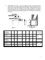
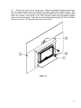
4.
POSITIONING THE UNIT: The more extended the insert, the greater the heat
transfer to the room. When installed as an extended insert, the front edge of the air
jacket will be installed flush with the fireplace facing. Otherwise the unit can be
moved back as much as 3.5" (89mm) or any position in between. The position
chosen will depend on your own preference for most installations (where the lintel is
less than 6" (152mm) and the depth is greater than 12.5" (318mm)). See the table
and Figure 5.
Figure 4
Figure 5
MAXIMUM
EXTENDED
I
J
L
M
N
O
P
AIR JACKET
INCHES
8 1/2
6 1/2
23 - 28
14 1/2
8
6
24
Flush
facing
MILLIMETERS
216
165
584-711
368
203
152
610
MINIMUM
EXTENDED
I
J
L
M
N
O
P
AIR JACKET
INCHES
12
10
23 - 28
18
4 1/2
2 1/2
20 1/2
Back
from
facing 3 1/2"
MILLIMETERS
305
254
584-711
457
114
64
521
with
14
5.
If lag-bolts and anchors are to be used to secure the insert, the hole locations
should be marked with the unit in place. Remove the unit and locate the anchors.
6.
Remove the faceplate panels from their box and assemble according to these
faceplate instructions:
A.
Remove the slide from within the air jacket.
B.
Place the faceplate face down on a flat, nonabrasive surface (see Figure 6) so that
the sides are a bit towards the middle.
Figure 6
C.
Place the slide onto the faceplate so that the bends of the faceplate pieces go
inside of the slide.
D.
Line up the holes by pushing the sides out and install (smooth heads inside) all the
bolts loosely. Line up the edge of the faceplate top and side, tighten the two bolts
joining them, and then tighten the side bolts. Tighten the bolts on the other side in
the same manner (see Figure 7).
Figure 7
15
7.
INSTALLATION ON FACEPLATE: Attach the mitred corners of trim together using
the corner brackets. Slide the assembled trim over the edge of the faceplate. See Figures
8 and 9.
Attach the left and right sides to the top with corner brackets supplied. Slip the trim over
the faceplate and snap the eight faceplate trim clips in place (see Figure 8).
Figure 8
Figure 9
8.
Lift the insert into the fireplace. Square the insert to the face of the fireplace by
adjusting the levelling legs on the sides at the rear of the insert. Check that the throat
connector is in line.
9.
If there is space to push the connector down from above, do so. Reach in through
the insert and pull the throat connector down into place. If you are securing the connector
to the flue collar with the screw, do that now.
16
10.
Push the air control (A) in, all the way. Slide the adjustable faceplate sleeve back
into its original location until the faceplate fits tightly against the fireplace facing. See
Figure 10. One 7/16" (11mm) open end wrench should be used to turn the nut (B), located
above the cooktop in the center, up so that it securely fastens the adjustable faceplate
sleeve to the top air jacket. Take the air control slider spring handle (C) from the firebox
and turn it onto the 1/4" diameter (6mm) air control rod (A).
Figure 10
17
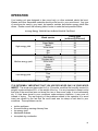
OPERATION
Your heating unit was designed to burn wood only; no other materials should be burnt.
Wastes and other flammable materials should not be burnt in your wood insert. Any type
of wood may be used in your insert, but specific varieties have better energy yields than
others. Please consult the following table in order to make the best possible choice.
Average Energy Yield Of One Air Dried Cord Of Cut Wood
Wood species
High energy yield
Medium energy yield
Low energy yield
Oak
Sugar Maple
Beech
Yellow birch
Ash
Elm
Larch (Tamarack)
Red Maple
Douglas red fir
Silver birch
Alder
Poplar
Hemlock
Spruce
Pine
Bass
Fir
Energy yield
(millions of BTU/cord)
29
28
26
25
24
23
23
23
23
22
18
17
17
17
17
16
13
Data provided by Energy, Mines and Resources - Canada
IT IS EXTREMELY IMPORTANT THAT YOU USE DRY WOOD ONLY IN YOUR WOOD
INSERT. The wood must have dried for 9 to 15 months, such that the humidity content (in
weight) is reduced below 20% of the weight of the log. It is very important to keep in mind
that even if the wood has been cut since one, two or even more years, it is not necessarily
dry, if it has been stored in poor conditions; under extreme conditions, it may even rot
instead of drying. The vast majority of the problems related to the operation of a wood
insert are caused by the fact that the wood used was too damp or had dried in poor
conditions. These problems can be:
ignition problems
creosote build-up causing chimney fires
low energy yield
blackened windows
incomplete log combustion
18
Smaller pieces of wood will dry faster. All logs exceeding 6" in diameter should be split.
The wood should not be stored directly on the ground. Air should circulate through the
cord. A 24" to 48" air space should be left between each row of logs, which should be
placed in the sunniest location possible. The upper layer of wood should be protected
from the element but not the sides.
TESTING YOUR WOOD
When the insert is thoroughly warmed, place one piece of split wood (about five inches in
diameter) parallel to the door on the bed of red embers. Keep the air control full open by
pulling on it and close the door. If ignition of the piece is accomplished within 90 seconds
from the time if was placed in the insert, your wood is correctly dried. If ignition takes
longer, your wood is damp. If your wood hisses and water or vapour escapes at the ends
of the piece, your wood is soaked or freshly cut. Do not use this wood in your insert.
Large amounts of creosote could be deposited in your chimney, creating potential
conditions for a chimney fire.
THE FIRST FIRES
The fresh paint on your insert needs to be cured to preserve its quality. Once the fuel
charge is properly ignited, only burn small fires in your insert for the first four hours of
operation. Never open the air control more than necessary to achieve a medium burn rate.
Make sure that there’s enough air circulation while curing the insert. The odours could be
smelled during the 3 or 4 first fires. The light smoke created by the paint curing process is
not toxic. Never start your insert outside. You will not be able to see if you are over
heating.
IGNITION
After making sure that the insert air intake controls are fully open, place several rumpled
sheets of paper in the centre of the combustion chamber. Place 8 to 10 pieces of small
dry kindling wood over the paper in the form of a tent. You may also place a few pieces of
heating wood, but choose the smaller ones. No chemical product should be used to light
the fire. Before igniting the paper and kindling wood, it is recommended that you warm up
the chimney. This is done in order to avoid back draft problems often due to negative
pressure in the house. If such is the case, open a window slightly near the insert and twist
together a few sheets of newspaper into a torch. Light up this paper torch and hold it as
close as possible to the mouth of the pipe inside the combustion chamber to warm up the
chimney. Once the updraft movement is initiated, you are ready to ignite the insert by
lighting the paper and kindling wood inside the combustion chamber. We therefore advise
you to leave the door slightly opened (1/4") for a 10 to 30 minutes period, under
supervision, in order to allow for good combustion. After this time, you must close the
door and progressively adjust the air control to obtain the desired temperature.
19
HEATING
Controlled combustion is the most efficient technique for wood heating because it enables
you to select the type of combustion you want for each given situation. The wood will burn
slowly if the wood insert air intake control is adjusted to reduce the oxygen supply in the
combustion chamber to a minimum. On the other hand, wood will burn quickly if the air
control is adjusted to admit a larger quantity of oxygen in the combustion chamber. The
air intake control on your insert is very simple. If you move it completely to the right, it is
fully open. If you move it completely to the left, it is fully close.
Your OSBURN insert burnt between .979 kg\h and 4.4 kg\h. of wood during EPA testing.
Real operating conditions may give very different results than those obtained in the lab
according to the species of wood used, its moisture content, the size and density of the
pieces, the length of the chimney, altitude and outside temperature.
In order to achieve an optimum efficiency from your unit, we suggest that you operate it
with the air control slightly open (approximately 10%). Make sure that you have a good
fire going and an adequate ember bed before you completely close the air control. Closing
the air control too soon will lower combustion efficiency and may cause the fire to die out.
The addition of a blower (if not already included) is highly recommended to maximize your
unit’s efficiency.
WARNINGS
NEVER
OVERFIRE YOUR INSERT. IF ANY PART OF THE INSERT STARTS TO GLOW RED, OVER
FIRING IS HAPPENING. READJUST THE AIR INTAKE CONTROL AT A LOWER SETTING.
THE INSTALLATION OF A LOG CRADLE IS NOT RECOMMENDED IN YOUR OSBURN WOOD INSERT.
NEVER PUT WOOD ABOVE THE FIREBRICK LINING OF THE FIREBOX.
RELOADING
Once you have obtained a good bed of embers, you should reload the unit. In order to do
so, open the air controls to maximum a few seconds prior to opening the insert's door.
Then proceed by opening the door very slowly; open it one or two inches for 5 to 10
seconds, before opening it completely to increase the draught and thus eliminate the
smoke which is stagnant in a state of slow combustion in the insert. Then bring the red
embers to the front of the insert and reload the unit.
For optimal operation of your wood insert, we recommend you to operate it with a wood
load approximately equivalent to the height of fire bricks.
It is important to note that wood combustion consumes ambient oxygen in the room .In the
case of negative pressure, it is a good idea to allow fresh air in the room, either by opening
a window slightly or by installing a fresh air intake system on an outside wall.
20
CREOSOTE FORMATION AND NEED FOR REMOVAL
When wood is burned slowly, it produces tar and other organic vapours, which combine
with expelled moisture to form creosote. The creosote vapours condense in the relatively
cool chimney flue of a slow-burning fire. As a result, creosote residue accumulates on the
flue lining. When ignited this creosote makes an extremely hot fire. When burning wood,
the chimney connector and chimney should be inspected at least once every two months
during the heating season to determine if a creosote build-up has occurred.
TO PREVENT CREOSOTE BUILD UP
Always burn dry wood. This allows clean burns and higher chimney temperatures,
therefore less creosote deposit.
Leave the air control full open for about 10 min. every time you reload the insert to
bring it back to proper operating temperatures. The secondary combustion can only
take place if the firebox is hot enough.
Always check for creosote deposit once every two months and have your chimney
cleaned at least once a year.
ASH DISPOSAL
Ashes should be removed from the insert every few days or when ashes get to 2 to 3
inches deep. Always empty the insert when it is cold, such as in the morning.
Always dispose of ashes in a metal container with a tight fitting lid. Place this container on
a non combustible floor or on the ground, well away from all combustible materials,
pending final disposal. If the ashes are disposed of by burial in soil or otherwise locally
dispersed, they should be retained in the close container until all cinders have thoroughly
cooled.
CAUTIONS:
ASHES COULD CONTAIN HOT EMBERS EVEN AFTER TWO DAYS WITHOUT OPERATING THE INSERT.
THE ASH PAN CAN BECOME VERY HOT. WEAR GLOVES TO PREVENT INJURY.
NEVER BURN THE INSERT WITH THE ASH TRAP OPEN. THIS WOULD RESULT IN OVER FIRING THE
INSERT. DAMAGE TO THE INSERT AND EVEN HOUSE FIRE MAY RESULT.
21
MAINTENANCE
Your OSBURN insert is a high efficiency insert and therefore require little maintenance. It
is important to perform a visual inspection of the insert every time it is emptied, in order to
insure that no parts have been damaged, in which case repairs must be performed
immediately.
GLASS
Inspect the glass regularly in order to detect any cracks. If you spot one, turn the insert
off immediately. Do not abuse the glass door by striking or slamming shut. Do not use
the insert if the glass is broken.
If the glass on your insert breaks, replace only with glazing supplied from the OSBURN
dealer.
To replace the glass, remove the screws retaining the gasket frame inside the door and
lift. Replace the damaged piece with a new one. Perform the procedure backwards
after replacing. When replacing the glass, you should change the glass gasket to
make sure you keep it sealed.
Never wash the glass with a product that may scratch. Use a specialized product,
available in the stores where wood inserts are sold.
The glass should be washed only when cold.
GASKETING
It is recommended that you change the door gasket (which makes your insert door air
tight) once a year, in order to insure good control over the combustion, maximum
efficiency and security. To change the door gasket, simply remove the damaged one.
Carefully clean the available gasket groove, apply a high temperature silicone sold for this
purpose, and install the new gasket. You may light up your insert again approximately 24
hours after having completed this operation.
WARNING:
NEVER
OPERATE THE INSERT WITHOUT A GASKET OR WITH A BROKEN ONE.
INSERT OR EVEN HOUSE FIRE MAY RESULT
DAMAGE
TO THE
PAINT
Only clean your insert with a dry soft cloth that will not harm the paint finish. If the paint
becomes scratched or damaged, it is possible to give your wood insert a brand new look,
by repainting it with a 1200o F heat resistant paint. For this purpose, simply scrub the
surface to be repainted with fine sand paper, clean it properly, and apply thin coats (2) of
paint successively.
22
BAFFLE INSTALLATION
All firebrick and ceramic wool baffles must be properly in place for correct burning
operation. Have any damaged firebricks replaced. Check the firebricks annually for
damage and replace if they are broken or damaged. See figure 11 for the firebrick layout.
VERMICULITE BAFFLE
TUBE
Figure 11 - Baffle installation
2
1 1 1/4" X 4 1/2" X 9"
2 VERMICULITE BAFFLE
3 1 1/4" X 1 7/8" X 4 1/2"
2
4 1 1/4" X 4 1/2" X 9"
LESS 7/8" X 5" WEDGE
5 1 1/4" X 2 3/16" X 9"
6 2 1/2" X 4 1/2" X 9"
7 1 1/4" X 4 1/2" X 9"
LESS 1" X 1" CORNER
4
6
3
5
1
6
6
7
6
1
5
4
1
1
5
3
1
1
5
7
Figure 12 - Firebrick layout
23
SECONDARY AIR TUBE REPLACEMENT
1.
Remove cotter pin at left end of tube.
2.
Slide tube to right and lower tube end below left plenum.
3.
Slide tube to left to remove.
4.
Reassemble in reverse order using a new cotter pin. The cotter pin is a
hammerlock style and locks into place by hitting the head sharply with a
hammer.
5.
Note that any tube can be replaced without disturbing the baffle.
#2
#1
The air tubes are identified for placement as follows:
Model
Type of tube
Osburn 1600 Insert
Front ► 22 holes of 1/4"
24
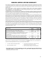
OSBURN LIMITED LIFETIME WARRANTY
The warranty of the manufacturer extends only to the original consumer purchaser and is not transferable. This warranty
covers brand new products only, which have not been altered, modified nor repaired since shipment from factory. Proof
of purchase (dated bill of sale), model name and serial number must be supplied when making any warranty claim to your
OSBURN dealer.
This warranty applies to normal residential use only. Damages caused by misuse, abuse, improper installation,
lack of maintenance, over firing, negligence or accident during transportation, power failures, downdrafts, or
venting problems are not covered by this warranty.
This warranty does not cover any scratch, corrosion, distortion, or discoloration. Any defect or damage caused by the use
of unauthorized parts or others than original parts void this warranty. An authorized qualified technician must perform the
installation in accordance with the instructions supplied with this product and all local and national building codes. Any
service call related to an improper installation is not covered by this warranty.
The manufacturer may require that defective products be returned or that digital pictures be provided to support the claim.
Returned products are to be shipped prepaid to the manufacturer for investigation. If a product is found to be defective,
the manufacturer will repair or replace such defect. Transportation fees to ship the product back to the purchaser will be
paid by the manufacturer. Repair work covered by the warranty, executed at the purchaser’s domicile by an authorized
qualified technician requires the prior approval of the manufacturer. Labour cost and repair work to the account of the
manufacturer are based on predetermined rate schedule and must not exceed the wholesale price of the replacement part.
All parts and labour costs covered by this warranty are limited according to the table below.
The manufacturer at its discretion may decide to repair or replace any part or unit after inspection and investigation of the
defect. The manufacturer may, at its discretion, fully discharge all obligations with respect to this warranty by refunding
the wholesale price of any warranted but defective parts. The manufacturer shall in no event be responsible for any
special, indirect, consequential damages of any nature, which are in excess of the original purchase price of the product.
A one-time replacement limit applies to all parts benefiting from a lifetime coverage. This warranty applies to products
purchased after October 1st, 2011.
WARRANTY APPLICATION
PARTS
LABOUR
DESCRIPTION
Combustion chamber (welds only), castings, convector air-mate, ceramic
glass (thermal breakage only*), and secondary air tubes*.
Plating* (defective manufacture) – subject to limitations above.
Stainless steel firebox components, surrounds and heat shields, ash drawer,
steel legs, pedestal, trims (aluminum extrusions), C-Cast baffle*, and
vermiculite baffle*.
Carbon steel firebox components, glass retainers, and handle assembly.
Blowers, heat sensors, switches, rheostat, wiring, and other controls.
Paint (peeling), gaskets, insulation, firebrick, and ceramic fibre blankets.
*Pictures required
Lifetime
5 years
Lifetime
n/a
7 years
5 years
5 years
2 years
1 year
3 years
1 year
n/a
Shall your unit or a components be defective, contact immediately your OSBURN dealer. Prior to your call make sure
you have the following information necessary to your warranty claim treatment:
Your name, address and telephone number;
Bill of sale and dealer’s name;
Serial number and model name as indicated on the
nameplate fixed to the back of your unit;
Nature of the defect and any relevant information.
Before shipping your unit or defective component to our plant, you must obtain from your OSBURN dealer an
Authorization Number. Any merchandise shipped to our plant without authorization will be refused
automatically and returned to sender.
25