1
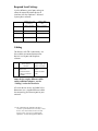
Technical Bulletin April, 2012 Opticom Central Management Software Communications Equipment Intended Use Opticom™ Central Management Software assists traffic maintenance personnel in the management of their Opticom™ system. In order for central management software to be deployed, communications must be deployed to the intersections where the Opticom Phase Selectors are installed. Global Traffic Technologies (GTT) has evaluated commercially available communications equipment for use with central management software. The equipment that has been evaluated is identified in this technical bulletin. Description This document describes the various communications devices that have been tested with the central management software and the device configuration used in our testing. Testing was performed in the GTT lab over the lab’s internal network. Testing was performed with Opticom Infrared phase selectors. Communications Overview Central management software is intended to be deployed on an IP (internet protocol) network. The traffic network between the central management software server (at the central site) and the intersections may include fiber, hardwired Ethernet, or wireless media and employ any number of intermediate devices. While central management software supports the use of TCP/IP to communicate with phase selectors, the current generation of Opticom phase selectors supports only serial protocol. Typically, this requires that a serial device server be installed in the traffic cabinet to bridge from an Ethernet switch in the cabinet to serial port on the phase selector. Alternatively, a communication device in the cabinet, such as a radio module or DSL over copper module, may include serial ports that can be cabled directly to the phase selector. While it’s easiest to use TCP/IP to communicate from the central management software server to the cabinet, the software can also use serial ports on the server. This is useful when, for example, you are using an older serial device server that does not support direct use of TCP/IP from the application. Support Disclaimer GTT will provide limited, high level support setting up and troubleshooting the devices listed in this technical bulletin. Our intent is to inform our customers of the devices that we have tested with the central management software and the setup configuration that we used in that testing as an aid in deciding the type of communications equipment to purchase. In-depth questions concerning the communications devices themselves should be directed to the manufacturer. Further, our testing has focused on compatibility between central management software, the serial device, and the Opticom phase selector. We have not tested other product quality factors such as reliability and environmental suitability. Use of a firewall on your central management software server, or between the server and the traffic network, may cause connection issues with some of these devices. It may be necessary to reconfigure your firewall in order to achieve reliable communication. Technical Support If you have any questions please call GTT Technical Support at 1-800-258-4610. Required Serial Settings Use the following serial port settings to allow the communication device to interface with the Opticom™ Infrared System phase selector: Baud rate Model 752 / 754 Infrared Phase Selectors 9600 Model 1000 GPS Phase Selectors1 115,200 Parity Data bits None 8 None 8 Flow control None None Cabling For devices with DB-9 connectors, use these cables to connect between the device’s serial port and the phase selector: Cable Model 752 / 754 Infrared Phase Selectors DB-9 to 6-pin miniDIN serial communications cable (GTT model C50005) Model 1000 GPS Phase Selectors2 DB-9 to DB-9 serial communications cable Some devices require different cables and/or additional adapters; see the “Cabling” section for the device. All serial device servers included in this document use a standard Ethernet cable for connecting the Ethernet port to your network. 1,2 This information on Opticom GPS phase selectors is provided for reference only. These devices were not included in the GTT lab testing as they were not yet supported by Opticom™ Central Management Software. PortServer® TS H MEI Turn off automatic IP address using DHCP. The PortServer TS H MEI is a serial server that provides RS-232 to Ethernet conversion and transport of serial data over an IP network. The PortServer® is available in 1,2 or 4 port versions. Specify the IP address to be used by this device. Directions included below may also be found in the Digi PortServer® TS Family Series Quick Start Guide and the User’s Guide for Digi One and PortServer® TS Family along with more detailed information about the device. Both documents are shipped with the PortServer® and are available on the Digi website at http://support.digi.com. Refer to the PortServer® User’s Guide for instructions on how to access the configurations via the internal webpages. Digi Equipment Corporation Pre-Installation On the back side of the unit is located a dip switch for each port. Ensure that the switch setting indicates RS-232 for the port to be connected to the phase selector. Cabling The Port Server has RJ45 connectors for each serial port. For Opticom™ Infrared System model 752 / 754 phase selectors, use an RJ45 to 6-pin DIN cable to connect the two serial ports together. GTT suggests the STREETCOM EZC-G6D EZ-Connect cable. Contact STREETCOM to purchase this cable. The STREETCOM web site is http://www.streetcom.net. Specify the Subnet Mask (usually 255.255.255.0). Specify the Default Gateway. Serial Port Configuration The serial port configuration consists of selecting the Serial Port Profile and the Basic Serial Settings. The Serial Port Profile specifies the type of transport communications means which will be used to ferry the RS-232 serial data over the IP network. Central management software supports TCP sockets and RealPort profiles. Installation of Digi’s RealPort COM port redirector software allows the remote devices to be installed as COM ports on a PC or server. Configure the Basic Serial Settings as described in the Required Serial Settings on page 3. Compatibility Test Configuration Device model: PortServer® TS 4 H MEI Device firmware: 82000747_U 11/09/2007 Network Configuration Comm modes: TCP/IP, redirected serial The PortServer must be setup to ensure the proper serial port settings are configured to communicate with the Opticom phase selector over the RS-232 interface and that the proper network configurations are made to allow the PortServer® to be found on the network by the central management software. The unit must be configured with a static IP address. Software: Central Management Software 1.5 ® Phase selector: Opticom Infrared Model 752 / 754 Moxa NPort 5110-T Moxa Corporation The NPort 5110-T is a serial server that provides RS-232 to Ethernet conversion and transport of serial data over an IP network. The NPort is available in 1 or 2 port versions. The two port version is the Models 5210-T. Directions included below may also be found in the NPort 5100 Series User’s Manual that is shipped with the 5110. The manual is also available on the Moxa website at http://www.moxa.com/product. The NPort 5110 comes with configuration software. Use of it can greatly simplify the installation and configuration process. Refer to Section 6 of the User’s Manual for additional information on the NPort Administrator software. Cabling The 5110 has a DB-9 connector for the serial port on the bottom edge. Use the standard serial cable as described on page 3. Network Configuration The 5110 must be setup to ensure the proper serial port settings are configured to communicate with the Opticom™ Infrared phase selector over the RS-232 interface and that the proper network configurations are made to allow the 5110 to be found on the network by the central management software. The unit must be configured with a static IP address. Specify the IP address to be used by this device. Specify the Subnet Mask (usually 255.255.255.0). Specify the Default Gateway. Specify IP Configuration as Static. Specify in the Accessible IPs list the specific IP addresses or group ranges that need to access the device. Refer to the Section 6 of the NPort 5100 Series User’s Manual for instructions on how to access the configurations. Serial Port Configuration The serial port configuration consists of selecting the Serial Settings from the webpage. Configure the Basic Serial Port Configuration as described in the Required Serial Settings on page 3. The Operating Settings specifies the type of transport communications means which will be used to ferry the RS-232 serial data over the IP network. Central management software supports TCP sockets and Real COM profiles. Select Operating Mode to: • TCP Server Mode to use TCP sockets. • Real COM Mode for COM port redirection, When Real COM mode is used, the COM port must be mapped using the COM Mapper. Refer to the NPort 5100 Series User’s Manual for instructions on how to access the configurations via the webpage interface. Compatibility Test Configuration Device model: 5110 Device firmware: 2.2 Build 08042219 Comm modes: TCP/IP, redirected serial Software: Central Management Software 1.5 Phase selector: Opticom Infrared Model 752 / 754 Airborne Industrial Wireless Device Server SSEW-100D Quatech Corporation Specify the Gateway Address. The SSEW-100D is a serial server that provides RS-232 to 802.11g conversion and transport of serial data over an IP network. The SSEW-100D is available in a one port version. The two port version is the DSEW-100D. Specify the Access Mode to Infrastructure. Directions included below may also be found in the Quatech Serial Device Server User’s Manual. The document is shipped with the SSEW-100D and is available on the Quatech website at http://wwwquatech.com. Cabling The SSEW-100D has a DB-9 connector for the serial port on the bottom edge. Use the standard serial cable as described on page 3. Antenna The standard antenna supplied with the unit is not suitable for external mounting. Additional antenna options are available from the vendor and third parties. Network Configuration The SSEW-100D must be setup to ensure the proper serial port settings are configured to communicate with the Opticom™ Infrared phase selector over the RS-232 interface and that the proper network configurations are made to allow the SSEW-100D to be found on the network by the central management software. The unit must be configured with a static IP address. Select Static IP address. Specify the IP address to be used by this device. Specify the Address Mask (usually 255.255.255.0). Specify an SSID for the access point to connect to. Specify any wireless security if needed. GTT tested with WPA-PSK. Refer to the SSEW-100D User’s Guide for instructions on how to access the configurations via the internal web pages. Serial Port Configuration The Serial Port Setup specifies the type of transport communications means which will be used to ferry the RS-232 serial data over the IP network. Central management software supports TCP sockets and COM ports. The SSEW-100D supports five (5) operating modes: Normal, Tunneling, Raw TCP, Auto TCP, and Raw UDP. Selection of Normal allows the unit to be used with COM redirector software. Specify Raw TCP mode for use with TCP sockets. Installation of the Quatech device as a multi-port serial device on a PC or server sets up the COM port redirector software so that the device appears as a COM port. Configure the serial port configuration as described in the Required Serial Settings on page 3. Compatibility Test Configuration Device model: SSEW-100D Device firmware: 6.39 Comm modes: TCP/IP, redirected serial. Testing was performed with a mix of wireless and hard-wired Ethernet Software: Central Management Software 1.5 Phase selector: Opticom Infrared Model 752 / 754 RMC-30 Ruggedcom Corporation The RMC-30 is a serial server that provides RS-232 to Ethernet conversion and transport of serial data over an IP network. Directions included below may also be found in the RMC30 Installation Guide and the ROS User’s Guide for RMC30 along with more detailed information about the device. Both documents are shipped with the RMC-30 and are available on the Ruggedcom website at http://www.ruggedcom.com. Cabling The RMC-30 has a terminal block for terminating the RS-232 serial connections and the RJ-45 Ethernet connector on the front of the unit. Refer to the RMC30 Installation guide for the wiring directions to make a custom cable and terminations. A standard Ethernet cable should be used for connecting the Ethernet port to your network. Network Configuration The RMC-30 must be setup to ensure the proper serial port settings are configured to communicate with the Opticom™ infrared phase selector over the RS-232 interface and that the proper network configurations are made to allow the RMC-30 to be found on the network by central management software. The unit must be configured with a static IP address. Refer to the User’s Guide for instructions on how to access the configurations via the internal web pages. Serial Port Configuration The Serial Port configuration specifies the type of transport communications means which will be used to ferry the RS-232 serial data over the IP network. Central management software supports TCP sockets and COM port profiles. Selection of RawSocket allows the central management software to connect to the RMC-30 via a TCP socket connection. Installation of Tracer IP COM port redirector software allows the remote devices to be installed as COM ports on a PC or server. Tracer IP is sold separately. GTT has not tested Tracer IP. Configure the serial port settings as described in the Required Serial Settings on page 3. Raw Socket Configuration The transport protocol configuration defines how the serial data is transported across the network. Specify Both for Direction. Specify TCP for the transport. Compatibility Test Configuration Device model: RMC-30-HI Device firmware: Boot v2.13.0, Main v3.5.0 Comm modes: TCP/IP Specify the address type as static. Software: Central Management Software 1.5 Specify the IP address to be used by this device. Phase selector: Opticom Infrared Model 752 / 754 Specify the Subnet Mask (usually 255.255.255.0). Specify the Default Gateway. RS910 Ruggedcom Corporation The RS910 is a serial server that provides RS-232 to Ethernet conversion and transport of serial data over an IP network. Two serial ports are provided on the unit. The RS910 is also available in a wireless version, the RS910W, if a wired connection is not desirable. Directions included below may also be found in the RS910 Installation Guide and the ROS User Guide for RS910/RS910L/RS910W/RS920L/ RS920W along with more detailed information about the device. Both documents are shipped with the RS910 and are available on the Ruggedcom website at http://www.ruggedcom.com. Cabling The RS910 has two DB-9 connectors on the front of the unit. Select one for use with the phase selector. Use the standard serial cable as described on page 4. In addition, this device requires a DB-9 Male to Male adapter and a null modem adapter to connect the two serial ports together. Network Configuration The RS910 must be setup to ensure the proper serial port settings are configured to communicate with the Opticom™ Infrared phase selector over the RS-232 interface and that the proper network configurations are made to allow the RS910 to be found on the network by central management software. The unit must be configured with a static IP address. Specify the address type as static. Specify the IP address to be used by this device. Specify the Subnet Mask (usually 255.255.255.0). Specify the Default Gateway. Refer to the User’s Guide for instructions on how to access the configurations via the internal web pages. Serial Port Configuration The Serial Port configuration specifies the type of transport communications means which will be used to ferry the RS-232 serial data over the IP network. Central management software supports TCP sockets and COM port profiles. Selection of RawSocket allows the central management software to connect to the RS910 via a TCP socket connection. Installation of Tracer IP COM port redirector software allows the remote devices to be installed as COM ports on a PC or server. Tracer IP is sold separately. GTT has not tested Tracer IP. Configure the serial port settings as described in the Required Serial Settings on page 3. Raw Socket Configuration The transport protocol configuration defines how the serial data is transported across the network. Specify Both for Direction. Specify TCP for the transport. Compatibility Test Configuration Device model: RS910-HI-D-S1-TX01-TX Device firmware: Boot v2.13.0, Main v3.5.0 Comm modes: TCP/IP Software: Central Management Software 1.5 Phase selector: Opticom Infrared Model 752 /754 ESR Series Industrial Ethernet Serial Server B&B Electronics The ESR series devices are serial servers that provide RS-232 to Ethernet conversion and transport of serial data over an IP network. ESR devices are available in 1, 2 or 4 port versions. Directions included below may also be found in the Quick Start Guide and the User’s Guide along with more detailed information about the device. Both documents are shipped with the ES1A and are available on the B&B Electronics website at http://www.bb-elec.com. Cabling The ESR has a DB-9 connector on one end and the RJ-45 Ethernet connector on the other end. Use the standard serial cable as described on page 3. Serial Port Configuration The Serial Port configuration specifies the type of transport communications means which will be used to ferry the RS-232 serial data over the IP network. On the “Serial” web page, set Serial port mode to RS-232. Configure the remaining serial as described in the Required Serial Settings on page 3. To use TCP/IP protocol, open the “Operation” web page, then select “TCP” and set Connection mode to Server. Use defaults for the other fields. Installation of VLINX Virtual COM Port software allows the remote devices to be installed as COM ports on a PC or server. Tracer IP is sold separately. GTT has not tested VLINX Virtual COM Port software. Compatibility Test Configuration Device model: ESR902 Device firmware: 2.0 Network Configuration Comm modes: TCP/IP The ESR must be setup to ensure the proper serial port settings are configured to communicate with the Opticom™ Infared phase selector over the RS-232 interface and that the proper network configurations are made to allow the ESR to be found on the network by central management software. The unit must be configured with a static IP address. On the “Operations” web page: Software: Central Management Software 1.5 Set DHCP to Disable. Specify the IP address to be used by this device. Specify the Netmask (usually 255.255.255.0). Specify the Default Gateway. Refer to the User’s Guide for instructions on how to access the configurations via the internal web pages. Phase selector: Opticom Infrared Model 752 / 754 B&B Electronics Model FOSTCDR Fiber Optic to RS-232 Serial Converter The B&B Electronics Model FOSTCDR fiber optic converter provides RS-232 serial to fiber optic conversion. The FOSTCDR should be used for serial extension to a location where the serial data can be converted to Ethernet or other networking means. No setup or configuration is required to use the unit. The serial connections are terminated on the front of the unit and the fiber connections are attached. At the head end, the fiber optic data is converted back to serial or directly to Ethernet. Consult the installation instructions that are shipped with the FOSTCDR for further information. Compatibility Test Configuration Device model: FOSTCDR Comm modes: TCP/IP Software: Central Management Software 1.5 Phase selector: Opticom™ Infrared Model 752 / 754 Moxa NPort Express DE-311 Moxa Corporation The NPort DE-311 is a serial server that provides RS-232 to Ethernet conversion and transport of serial data over an IP network. The DE-311 does not meet the NEMA TS2 temperature specification. Directions included below may also be found in the NPort Family Software Installation Guide that is shipped with the DE-311. The manual is also available on the Moxa website at http://www.moxa.com/product. The NPort DE-311 comes with configuration software. Use of it can greatly simplify the installation and configuration process. Refer to the installation guide for additional information on the NPort Management suite. The suite contains two individual programs: Configurator and Real COM Installer. Cabling The DE-311 has a DB-9 connector for the serial port on the bottom edge. Use the standard serial cable as described on page 3. In addition, this device requires a DB-9 Male to Male adapter and a null modem adapter to connect the two serial ports together. Network Configuration The DE-311 must be setup to ensure the proper serial port settings are configured to communicate with the Opticom™ Infrared phase selector over the RS-232 interface and that the proper network configurations are made to allow the DE311 to be found on the network by the central management software. The unit must be configured with a static IP address. Specify the IP address to be used by this device. Specify the Subnet Mask (usually 255.255.255.0). Specify the Default Gateway. Specify IP Configuration as Static IP. Specify the Access Control list to control by IP Address and add in specific IP addresses or group ranges. Refer to the Section 5 of the NPort Family Software Installation Guide for instructions on how to access the configurations via the webpage interface. Serial Port Configuration The serial port configuration consists of selecting the Serial Settings from the webpage. Configure the Basic Serial Port Configuration settings as described in the Required Serial Settings on page 3. The Operating Mode specifies the type of transport communications means which will be used to ferry the RS-232 serial data over the IP network. Central management software supports TCP sockets and Real COM profiles. Select Operating Mode to: • Real COM Mode for COM port redirection, • TCP Server Mode to use TCP sockets. When Real COM mode is used, the COM port must be mapped using the Real COM Installer which is a separate utility independent of the Management software. Refer to the NPort Family Software Installation Guide for instructions on how to access the configurations via the webpage interface or via the NPort Management Suite. Compatibility Test Configuration Device model: DE311 Device firmware: 2.7 Comm modes: TCP/IP, redirected serial Software: Central Management Software 1.5 Phase selector: Opticom™ Infrared Model 752 / 754 Device Master® RTS Comtrol Corporation Serial Port Configuration The Comtrol Device Master RTS is available in many different port configurations. The Device Master® family can be purchased with either RJ45 connectors or DB-9 connectors. ® Directions included below may also be found in the Device Master® RTS User Guide and the NS-Link User’s Guide. Both documents are shipped with the Device Master® and are available on the Comtrol website at http://www.comtrol.com. The serial port configuration specifies the type of transport communications means which will be used to ferry the RS-232 serial data over the IP network. Central management software supports TCP sockets and Com Ports. Cabling Installation of the Device Master as a multi-port serial adapter and the associated COM ports establishes the COM port redirector and allows the remote devices to be installed as COM ports on a PC or server. The Device Master can be configured via the PortVision software or via the internal web pages of the device. The Device Master® has RJ-45 or DB-9 connectors on end and the RJ-45 Ethernet connector on the other end. Use the standard serial cable as described on page 4. Configure the serial settings as described in the Required Serial Settings on page 3.Specify TCP connection configuration as enable TCP connections, enable listen, set “connect on” to always on. Network Configuration The Device Master® must be setup to ensure the proper serial port settings are configured to communicate with the Opticom™ Infrared phase selector over the RS-232 interface and that the proper network configurations are made to allow the Device Master® to be found on the network by the central management software. The unit must be configured with a static IP address. Turn off automatic IP address using DHCP. Specify the IP address to be used by this device. Specify the Subnet Mask (usually 255.255.255.0). Specify the Default Gateway. Refer to the Device Master® RTS User’s Guide for instructions on how to access the configurations via the internal web pages. Compatibility Test Configuration Device model: DeviceMaster RTS 4-port Device firmware: 5.17 Comm modes: TCP/IP, redirected serial Software: Central Management Software 1.5 Phase selector: Opticom Infrared Model 752 / 754 ES1A Mini Ethernet to RS-232 Converter B&B Electronics The ES1A is a serial server that provides RS-232 to Ethernet conversion and transport of serial data over an IP network. The ES1A does not meet the TS2 temperature specification. Directions included below may also be found in the Quick Start Guide and the User’s Guide along with more detailed information about the device. Both documents are shipped with the ES1A and are available on the B&B Electronics website at http://www.bb-elec.com. Cabling The ES1A has a DB-9 connector on one end and the RJ-45 Ethernet connector on the other end. Use the standard serial cable as described on page 3. Network Configuration The ES1A must be setup to ensure the proper serial port settings are configured to communicate with the Opticom™ Infrred phase selector over the RS-232 interface and that the proper network configurations are made to allow the ES1A to be found on the network by central management software. The unit must be configured with a static IP address. Turn off automatic IP address using DHCP. Specify the IP address to be used by this device. Specify the Subnet Mask (usually 255.255.255.0). Specify the Default Gateway. Refer to the User’s Guide for instructions on how to access the configurations via the internal web pages. Serial Port Configuration The serial port configuration consists of selecting the Serial Port Profile and the Basic Serial Settings. The Serial Port Profile specifies the type of transport communications means which will be used to ferry the RS-232 serial data over the IP network. Central management software supports TCP sockets and RealPort profiles. Installation of RealPort COM port redirector software allows the remote devices to be installed as COM ports on a PC or server. Configure the Basic Serial Settings as described in the Required Serial Settings on page 3. Compatibility Test Configuration Device model: ES1A Device firmware: 1.9.0.6 Boot: 0.0.0.1 POST: 1.1.3 Comm modes: TCP/IP, redirected serial Software: Central Management Software 1.5 Phase selector: Opticom Infrared Model 752 / 754 PortServer® and RealPort® are registered trademarks of Digi, International NPort® is a registered trademark of Moxa, Incorporated SSEW-100D is a product of Quatech, Incorporated RuggedServer™ RMC30 is a trademark of Ruggedcom Corporation Device Master® RTS is a registered trademark of Comtrol Corporation Global Traffic Technologies, LLC Global Traffic Technologies Canada, Inc. Opticom is a trademark of Global 7800 Third Street North 157 Adelaide Street West St. Paul, Minnesota 55128-5441 Suite 448 Traffic Technologies, LLC Used under license in Canada 1-800-258-4610 Toronto, ON M5H 4E7 Windows is a registered trademark of the Microsoft Corporation in the United States 651-789-7333 Canada Please recycle. Printed in the U.S.A. www.gtt.com 1-800-258-4610 @ Global Traffic Technologies, LLC 2012 All rights reserved. 79-1000-0275-0 C