1
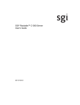
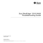
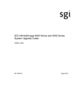
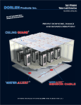
SGI InfiniteStorage IS2224 Installation and Overview Guide 007-5830-002 The information in this document supports the SGI InfiniteStorage 2224 (IS2224) storage system. 620J Storage Enclosure Installation and Overview Guide 46129-00, Rev. A Proprietary Rights Notice This document contains proprietary information of LSI Corporation. The information contained herein is not to be used by or disclosed to third parties without the express written permission of an officer of LSI Corporation. Document Description Document 46129-00, Rev. A. March 2010 This document will remain the official reference source for all revisions and releases of this product until rescinded by an update. Disclaimer It is the policy of LSI Corporation to improve products as new technology, components, software, and firmware become available. LSI reserves the right to make changes to any products herein at any time without notice. All features, functions, and operations described herein may not be marketed by LSI in all parts of the world. In some instances, photographs and figures are of equipment prototypes. Therefore, before using this document, consult your LSI representative for information that is applicable and current. LSI DOES NOT ASSUME ANY RESPONSIBILITY OR LIABILITY FOR THE USE OF ANY PRODUCTS DESCRIBED HEREIN EXCEPT AS EXPRESSLY AGREED TO IN WRITING BY LSI. LSI products are not intended for use in life-support appliances, devices, or systems. Use of any LSI product in such applications without written consent of the appropriate LSI officer is prohibited. License Restriction The purchase or use of an LSI Corporation product does not convey a license under any patent, copyright, trademark, or other intellectual property right of LSI or third parties. Copyright Notice © 2010 LSI Corporation. All rights reserved. Trademark Acknowledgments LSI, the LSI logo, HotScale, SafeStore, SANshare, SANtricity, Simplicity, and XBB are trademarks or registered trademarks of LSI Corporation. All other brand and product names may be trademarks of their respective companies. Contents CHAPTER 1: PREPARING FOR AN INSTALLATION Key Terms ............................................................................................................................................................1-1 environmental services monitor (ESM) ..............................................................................................1-1 storage array ................................................................................................................................................1-2 storage enclosure ......................................................................................................................................1-2 Gathering Items ................................................................................................................................................1-2 Basic Hardware............................................................................................................................................1-2 Cables and Connectors ............................................................................................................................1-3 Tools and Other Items ..............................................................................................................................1-3 Things to Know – Taking a Quick Glance at the Hardware ...............................................................1-4 CHAPTER 2: INSTALLING THE STORAGE ENCLOSURE Things to Know – General Installation......................................................................................................2-1 Steps to Install – Storage Enclosure...........................................................................................................2-2 Steps to Install – Drives and Drive Canisters ..........................................................................................2-9 Things to Know – Connecting Power Cords........................................................................................ 2-10 Steps to Connect – Power Cords ............................................................................................................. 2-11 CHAPTER 3: CONNECTING THE STORAGE ENCLOSURE TO THE HOST Key Terms ............................................................................................................................................................3-1 drive channel ...............................................................................................................................................3-1 Things to Know – Connecting the Storage Enclosure to a Host .....................................................3-2 Things to Know – Connecting the Storage Enclosure to Another Storage Enclosure ............3-2 Steps to Connect – Storage Enclosures with the Power Off .............................................................3-3 Steps to Connect – Storage Enclosure with the Power On ...............................................................3-4 Things to Know – Basic Cabling Configurations ...................................................................................3-5 620J Storage Enclosure Installation and Overview Guide i CHAPTER 4: TURNING ON THE POWER AND CHECKING FOR PROBLEMS Steps to Turn On – Power..............................................................................................................................4-1 Steps to Check for Problems – Storage Enclosure ...............................................................................4-2 LEDs on the Storage Enclosure .............................................................................................................4-3 ID Diagnostic Codes on the Seven-Segment Display...................................................................4-8 General Behavior of the LEDs ................................................................................................................4-9 Service Action LEDs................................................................................................................................ 4-11 APPENDIX A: ADDING A SECOND ENVIRONMENTAL SERVICES MONITOR (ESM) CANISTER ii 620J Storage Enclosure Installation and Overview Guide Chapter 1 Preparing for an Installation Use this document to install the 620J storage enclosure. If you are adding the storage enclosure to an existing storage array, look at the profile for your storage array. The profile shows information about the number of drives that are supported by your storage array, such as the following: • The number of drives that are currently attached to the host • The number of drives that you are allowed to add to the host Make sure that your storage array supports adding more drives. ATTENTION Possible hardware damage – To prevent electrostatic discharge damage to the storage enclosure, use proper antistatic protection when handling the components. Navigational Aid “Key Terms“ Page 1-1 “Gathering Items“ Page 1-2 “Things to Know – Taking a Quick Glance at the Hardware“ Page 1-4 Key Terms environmental services monitor (ESM) A canister in the storage enclosure that monitors the status of the components. An ESM also serves as the connection point to transfer data between the storage enclosure and the host. 620J Storage Enclosure Installation and Overview Guide 1-1 Preparing for an Installation. . . . . . . . . . . . . . . . . . . . . . . . . . . . . . . . . . . . . . . . . . . . . . . . . . . . . . . . storage array A collection of both physical components and logical components for storing data. Physical components include drives, controllers, fans, and power supplies. Logical components include volume groups and volumes. These components are managed by the storage management software. storage enclosure One enclosure with drives, one (or optionally, two) environmental services monitors (ESMs), power supplies, and fans. A JBOD storage enclosure does not contain RAID controllers. Gathering Items Before you start the installation, make sure that the hardware items and the software items have been approved by the original manufacturer. If you need more information, contact your Customer and Technical Support representative. Basic Hardware Basic Hardware and Tools Item Included with the Storage Enclosure 620J storage enclosure with end caps that are packaged separately. Mounting rails, clip nuts, and screws The mounting rails that are available with the storage enclosure are designed for an industrystandard cabinet. 1-2 Optional 620J Storage Enclosure Installation and Overview Guide . . . . . . . . . . . . . . . . . . . . . . . . . . . . . . . . . . . . . . . . . . . . . . . . . . . . . . . . . . . . . . . . Gathering Items Cables and Connectors Item Included with the Storage Enclosure Power cords The power cords that are shipped with the storage enclosure are for connection to an external power source, such as a wall plug. Your cabinet might have special power cords that you use instead of the power cords that are shipped with the storage enclosure. SAS cables (for connections within the storage array) Not included • Depending on your connection requirements, you need to purchase additional cables or cables of different lengths. Consult with your system supplier. Tools and Other Items • Labels – To help you to identify cable connections and to more easily trace cables • A cart – To hold the storage enclosure and its components • A Phillips screwdriver • A flat-blade screwdriver • Antistatic protection • A flashlight 620J Storage Enclosure Installation and Overview Guide 1-3 Preparing for an Installation. . . . . . . . . . . . . . . . . . . . . . . . . . . . . . . . . . . . . . . . . . . . . . . . . . . . . . . . Things to Know – Taking a Quick Glance at the Hardware ATTENTION Risk of equipment malfunction – To avoid exceeding the functional and environmental limits, install only drives that have been approved by your supplier. Drives might be shipped but not installed. System integrators, resellers, system administrators, or users can install drives. IMPORTANT Each storage enclosure in the storage array must have a minimum of two drives for proper operation. If an enclosure has fewer than two drives, a power supply error is reported. Figure 1–1 620J Storage Enclosure – Front View 1 Left End Cap (has the storage enclosure LEDs) 2 Drive Canisters 3 Right End Cap Figure 1–2 620J Storage Enclosure – Rear View 1 2 3 4 5 6 7 11 97002-09 8 9 10 8 9 10 1 ESM A Canister 2 Host SFF-8088 Connector 1 3 Host SFF-8088 Connector 2 4 Seven Segment Display Indicators 5 Serial Connector 6 Ethernet Connector 7 Expansion Port SFF-8088 Connector 8 Power-Fan Canister 9 Power Connector 10 Power Switch 11 Blank ESM B Canister 1-4 620J Storage Enclosure Installation and Overview Guide Chapter 2 Installing the Storage Enclosure Navigational Aid “Things to Know – General Installation“ Page 2-1 “Steps to Install – Storage Enclosure“ Page 2-2 “Steps to Install – Drives and Drive Canisters“ Page 2-9 “Things to Know – Connecting Power Cords“ Page 2-10 “Steps to Connect – Power Cords“ Page 2-11 Things to Know – General Installation IMPORTANT If you are installing the storage enclosure in a cabinet with other enclosures, make sure that the combined power and weight requirements of the storage enclosure and the other enclosures do not exceed the capacity of your cabinet. • Special site preparation is not required for this storage enclosure beyond what is normally found in a computer environment. • The power supplies meet standard voltage requirements for both domestic and worldwide operation. • If you are installing multiple storage enclosures within a cabinet, keep as much weight as possible in the bottom half of the cabinet. IMPORTANT After you install the storage enclosures, you might replace drives or install additional drives. If you replace or add more than one drive without powering down the storage enclosure, install the drives one at a time. Wait 10 seconds after you insert each drive before inserting the next one. 620J Storage Enclosure Installation and Overview Guide 2-1 Installing the Storage Enclosure . . . . . . . . . . . . . . . . . . . . . . . . . . . . . . . . . . . . . . . . . . . . . . . . . . . . ATTENTION Possible hardware damage – To prevent electrostatic discharge damage to the storage enclosure, use proper antistatic protection when handling storage enclosure components. Steps to Install – Storage Enclosure WARNING (W08) Risk of bodily injury – Two persons are required to safely lift the component. WARNING (W05) Risk of bodily injury – If the bottom half of the cabinet is empty, do not install components in the top half of the cabinet. If the top half of the cabinet is too heavy for the bottom half, the cabinet might fall and cause bodily injury. Always install a component in the lowest available position in the cabinet. 2-2 620J Storage Enclosure Installation and Overview Guide . . . . . . . . . . . . . . . . . . . . . . . . . . . . . . . . . . . . . . . . . . . . . . . . .Steps to Install – Storage Enclosure This procedure describes how to install the mounting rails into an industry standard cabinet. 1 Make sure that the cabinet is in the final location. Make sure that you meet the clearance requirements shown in Figure 2–1. Figure 2–1 Storage Enclosure Airflow and Clearance Requirements 1 76 cm (30 in.) clearance in front of the cabinet 2 61 cm (24 in.) clearance behind the cabinet NOTE Fans pull air through the storage enclosure from front to back across the drives. 2 Lower the feet on the cabinet to level it and to keep the cabinet from moving. 3 Remove the storage enclosure and all contents from the shipping carton. 620J Storage Enclosure Installation and Overview Guide 2-3 Installing the Storage Enclosure . . . . . . . . . . . . . . . . . . . . . . . . . . . . . . . . . . . . . . . . . . . . . . . . . . . . 4 Position the mounting rails in the cabinet. Figure 2–2 Positioning the Mounting Rails in the Cabinet 1 2 3 4 5 2-4 Mounting Rail Existing Storage Enclosure Clearance Above and Below the Existing Enclosure Screws for Securing the Mounting Rail to the Cabinet (Front and Rear) Industry Standard Cabinet If you are installing the mounting rails above an existing storage enclosure, position the mounting rails directly above the storage enclosure. If you are installing the mounting rails below an existing storage enclosure, allow 8.8-cm (3.5-in.) vertical clearance for a storage enclosure. 620J Storage Enclosure Installation and Overview Guide . . . . . . . . . . . . . . . . . . . . . . . . . . . . . . . . . . . . . . . . . . . . . . . . .Steps to Install – Storage Enclosure 5 Attach the mounting rails to the cabinet by performing these substeps: a Make sure that the adjustment screws on the mounting rail are loose so that the mounting rail can extend or contract as needed. Figure 2–3 Attaching the Mounting Rails to the Cabinet 1 2 3 4 Cabinet Mounting Holes Adjustment Screws for Locking the Mounting Rail Length Mounting Rails Clip for Securing the Rear of the Storage Enclosure b Place the mounting rail inside the cabinet, and extend the mounting rail until the flanges on the mounting rail touch the inside of the cabinet. c Make sure that the alignment spacers on the front flange of the mounting rail fit into the mounting holes in the cabinet (Figure 2–4 on page 2-6). The front flange of each mounting rail has two alignment spacers. The alignment spacers are designed to fit into the mounting holes in the cabinet. The alignment spacers help position and hold the mounting rail. 620J Storage Enclosure Installation and Overview Guide 2-5 Installing the Storage Enclosure . . . . . . . . . . . . . . . . . . . . . . . . . . . . . . . . . . . . . . . . . . . . . . . . . . . . Figure 2–4 Alignment Spacers on the Mounting Rail 1 Alignment Spacers d Insert one M5 (12mm) screw through the front of the cabinet, and screw into the top captured nut in the mounting rail. e Insert two M5 (12mm) screws through the rear of the cabinet and screw into the captured nuts in the rear flange in the mounting rail. f Tighten the adjustment screws on the mounting rail. g Repeat substep a through substep f to install the second mounting rail on the other side of the cabinet. 6 With the help of one other person, slide the rear of the storage enclosure onto the mounting rails. The rear edge of the storage enclosure must fit into the clip on the mounting rail. The storage enclosure is correctly aligned when these conditions are met on both mounting rails: 2-6 The mounting holes on the front flanges of the storage enclosure align with the mounting holes on the front of the mounting rails. The rear edge of the storage enclosure sheet metal fits into the clip on the mounting rail (Figure 2–5 on -page 2-7). The holes in the storage enclosure sheet metal for the rear hold-down screws align with the captured nuts in the side of the mounting rails. 620J Storage Enclosure Installation and Overview Guide . . . . . . . . . . . . . . . . . . . . . . . . . . . . . . . . . . . . . . . . . . . . . . . . .Steps to Install – Storage Enclosure Figure 2–5 Sliding the Storage Enclosure into the Clip on the Mounting Rail 4 1 2 3 78039-10 1 2 3 4 Mounting Rail Clip Partial View of the Storage Enclosure Rear Sheet Metal Align the hole in the storage enclosure sheet metal with the captured nut in the mounting rail. 7 Secure the front of the storage enclosure to the cabinet. Use the two screws to attach the flange on each side of the front of the storage enclosure to the mounting rails (Figure 2–6). a Insert one M5 (12mm) screw through the bottom hole of a flange on the storage enclosure so that the screw goes through the cabinet rail and engages the bottom captured nut in the mounting rail. Tighten the screw. b Repeat substep a for the second flange on the other side of the cabinet. Figure 2–6 Attaching the Front of the Storage Enclosure 1 Screws for Securing the Front of the Storage Enclosure 620J Storage Enclosure Installation and Overview Guide 2-7 Installing the Storage Enclosure . . . . . . . . . . . . . . . . . . . . . . . . . . . . . . . . . . . . . . . . . . . . . . . . . . . . 8 Secure the side of the storage enclosure to the mounting rails by performing these substeps: a Insert one M4 (8mm) screw through the side sheet metal of the storage enclosure into the captured nut on the side of the mounting rail. Tighten the screw. b Repeat substep a for the other side. 9 Attach the plastic end caps onto the front of the storage enclosure. Notice that the left end cap has holes so the LEDs can be seen through them after the left end cap is attached to the storage enclosure (Figure 2–7). a Put the top of the end cap on the hinge tab that is part of the storage enclosure mounting flange. b Gently press on the bottom of the end cap until it snaps into place over the retainer on the bottom of the storage enclosure mounting flange. Figure 2–7 Attaching the End Caps to the 620J Storage Enclosure 96006-01 1 2 1 Hinge Tab 2 Retainer 2-8 620J Storage Enclosure Installation and Overview Guide . . . . . . . . . . . . . . . . . . . . . . . . . . . . . . . . . . . . . . . . . . Steps to Install – Drives and Drive Canisters Steps to Install – Drives and Drive Canisters Storage enclosures are delivered without the drives installed in the drive canisters. Follow the steps in this procedure to install the drives in the canisters and then to install the canisters in the storage enclosure. If you have already installed the drive canisters in the storage enclosure, you can skip this step and go to “Things to Know – Connecting Power Cords” on page 2-10. ATTENTION Risk of equipment malfunction – To avoid exceeding the functional and environmental limits, install only drives that have been approved by your supplier. System integrators, resellers, system administrators, or users can install the drives. 1 Position the drive in the drive canister, being sure to align the drive properly toward the back (opened end) of the canister. Secure the drive with two screws on each side of the canister (Figure 2–8). 2 Be sure the four screws are tightened and will hold the drive securely in the drive canister. The HDD mounting screws should be tightened to 4 in-lb to securely hold the drive in the drive canister. Figure 2–8 Installing a Drive in a Drive Canister 1 2 96009-01 1 Drive 2 Drive Canister 620J Storage Enclosure Installation and Overview Guide 2-9 Installing the Storage Enclosure . . . . . . . . . . . . . . . . . . . . . . . . . . . . . . . . . . . . . . . . . . . . . . . . . . . . 3 To install the drive canister in the storage enclosure, place the drive canister on the slot guides of the storage enclosure, and slide the canister all the way into the slot. 4 Rotate the drive canister handle down to lock the drive canister securely in place (Figure 2–9). Figure 2–9 Installing a Drive Canister in a Storage Enclosure 1 96007-01 1 Drive Handle Things to Know – Connecting Power Cords • For each AC power connector on the storage enclosure, make sure that you use a separate power source in the cabinet. Connecting to independent power sources maintains power redundancy. • To ensure proper cooling and assure availability, the storage enclosure always uses two power supplies. • You can use the power cords shipped with the storage enclosure with typical outlets, such as a wall receptacle. IMPORTANT Make sure that you do not turn on the power to the storage enclosure until this installation and overview guide instructs you to do so. For the correct procedure for turning on the power, see “Steps to Turn On – Power” on page 4-1. 2-10 620J Storage Enclosure Installation and Overview Guide . . . . . . . . . . . . . . . . . . . . . . . . . . . . . . . . . . . . . . . . . . . . . . . . . . . Steps to Connect – Power Cords Steps to Connect – Power Cords 1 Make sure that the circuit breakers in the cabinet are turned off. 2 Make sure that both of the Power switches on the storage enclosures are turned off. 3 Connect the primary power cords from the cabinet to the external power source (Figure 2–10). Figure 2–10 Power Switches on a Storage Enclosure 97002-10 1 1 Power Switches 620J Storage Enclosure Installation and Overview Guide 2-11 Installing the Storage Enclosure . . . . . . . . . . . . . . . . . . . . . . . . . . . . . . . . . . . . . . . . . . . . . . . . . . . . 2-12 620J Storage Enclosure Installation and Overview Guide Chapter 3 Connecting the Storage Enclosure to the Host Navigational Aid “Key Terms“ Page 3-1 “Things to Know – Connecting the Storage Enclosure to a Host“ Page 3-2 “Things to Know – Connecting the Storage Enclosure to Another Storage Enclosure” Page 3-2 “Steps to Connect – Storage Enclosures with the Power Off“ Page 3-3 “Steps to Connect – Storage Enclosure with the Power On“ Page 3-4 “Things to Know – Basic Cabling Configurations“ Page 3-5 Key Terms drive channel The path for the transfer of data between the hosts and the drives in the storage array. 620J Storage Enclosure Installation and Overview Guide 3-1 Connecting the Storage Enclosure to the Host . . . . . . . . . . . . . . . . . . . . . . . . . . . . . . . . . . . . . . . . . Things to Know – Connecting the Storage Enclosure to a Host You can connect a storage enclosure to a new host or to an existing host. Before you connect a storage enclosure to an existing host, you must answer these questions: • How many storage enclosures does this host support? This information is located in the storage array profile for your storage array. • What is the cabling configuration for the storage array? See “Things to Know – Basic Cabling Configurations“ on page 3-5. • Is the storage array receiving power? No, see “Steps to Connect – Storage Enclosures with the Power Off“ on page 3-3. • Is the storage array transferring I/O data? Yes, see “Steps to Connect – Storage Enclosure with the Power On“ on page 3-4. Things to Know – Connecting the Storage Enclosure to Another Storage Enclosure The ESM in each storage enclosure has three SAS connectors. Below two of the connectors is an arrow pointing up. Below the expansion connector on the far right is an arrow pointing down. When connecting from an ESM in one storage enclosure to an ESM in another storage enclosure, make sure that you use connectors with arrows pointing in opposite directions. ESMs are connected to ESMs in other storage enclosures (or most hosts) via cables with a standard 4-lane SFF8088 connector on each end. Ease-of-use implies that the cables have a “universal key.” Otherwise, the two ends of the cables might need to be switched with each other so that they match with the proper ESM connectors. High-quality, compatible cables with universal keys from LSI are available from your system supplier. Table 3–1 Cable Part Numbers and Lengths LSI Part Number 3-2 Cable Length CBL - SFF8088SAS-10M 1.0 meter CBL - SFF8088SAS-20M 2.0 meter 620J Storage Enclosure Installation and Overview Guide . . . . . . . . . . . . . . . . . . . . . . . . . . . . . . Steps to Connect – Storage Enclosures with the Power Off Steps to Connect – Storage Enclosures with the Power Off 1 Plug one end of the cable into the drive expansion connector on the host. 2 Plug the other end of the cable into the connector with an up arrow on the ESM in the storage enclosure. 3 Are you adding more storage enclosures? Yes – Continue with step 4. No – Continue with step 7. 4 From the first storage enclosure, plug one end of the cable into the connector with the down arrow. IMPORTANT Each ESM in the storage enclosure has three SAS connectors. Two connectors show an up arrow; the other connector shows a down arrow. When connecting from an ESM in one storage enclosure to an ESM in another storage enclosure, connect from a down arrow to an up arrow. If the cable is plugged into two connectors with arrows pointing in the same direction, communication between the two storage enclosures is lost. 5 Plug the other end of the cable into the connector with an up arrow on the next storage enclosure. 6 Repeat step 4 through step 5 for each storage enclosure that you intend to add to the storage array. 7 Repeat step 1 through step 6 for a second host. 620J Storage Enclosure Installation and Overview Guide 3-3 Connecting the Storage Enclosure to the Host . . . . . . . . . . . . . . . . . . . . . . . . . . . . . . . . . . . . . . . . . Steps to Connect – Storage Enclosure with the Power On 1 Is the storage array transferring I/O data? Yes – Go to step 2. No – Go to step 5. 2 Can you stop transferring all I/O data to the storage array? Yes – Go to step 3. Supervision from your Customer and Technical Support representative is not required. No – Contact your Customer and Technical Support representative before connecting a storage enclosure to a storage array that is transferring I/O data. The Customer and Technical Support representative will help you connect the storage enclosure to a storage array that is transferring I/O data. 3 Stop all I/O activity to the storage array. 4 Are you adding the storage enclosure to a storage array with existing storage enclosures? Yes – Go to step 5. No – Go to step 8. 5 Plug one end of the cable into the drive expansion connector on the host. IMPORTANT Each ESM in the storage enclosure has three SAS connectors. Two connectors show an up arrow; the other connector shows a down arrow. When connecting from an ESM in one storage enclosure to an ESM in another storage enclosure, connect from a down arrow to an up arrow. If the cable is plugged into two connectors with arrows pointing in the same direction, communication between the two storage enclosures is lost. 6 Plug the other end of the cable into the connector with an up arrow on the ESM in the storage enclosure. 7 Are you adding more storage enclosure? 3-4 Yes – Go to step 5. No – Go to step 8. 620J Storage Enclosure Installation and Overview Guide . . . . . . . . . . . . . . . . . . . . . . . . . . . . . . . . . . . . . . . . Things to Know – Basic Cabling Configurations 8 From the first storage enclosure, plug one end of the cable into the connector with the down arrow. 9 Plug the other end of the cable into the connector with an up arrow on the next storage enclosure. 10 Repeat step 8 through step 9 for each storage enclosure that you intend to add to the storage array. 11 Repeat step 5 through step 10 for controller B. Things to Know – Basic Cabling Configurations You have many options for attaching cables in your storage array configuration. Use these basic configurations as a guide to configure your storage array. Depending on the number ESMs, hosts, and storage enclosures that you need to connect, see the applicable figure listed in Table 3-2. Table 3-2 Cabling Configurations Cabling Configuration Figure Simple Configuration: Single ESM, single host, and Figure 3–1 on page 3-6 single storage enclosers Single ESM, single host, and multiple storage enclosures Figure 3–2 on page 3-6 Single ESM, dual host, and multiple storage enclosures Figure 3–3 on page 3-7 Dual ESMs, dual hosts, and multiple storage enclosures Figure 3–4 on page 3-7 620J Storage Enclosure Installation and Overview Guide 3-5 Connecting the Storage Enclosure to the Host . . . . . . . . . . . . . . . . . . . . . . . . . . . . . . . . . . . . . . . . . Figure 3–1 Simple Configuration: Single ESM, Single Host, and Single Storage Enclosure HOST 1 ESM A 97009-01 Figure 3–2 Single ESM, Single Host, and Multiple Storage Enclosures HOST 1 ESM A ESM A ESM A 3-6 620J Storage Enclosure Installation and Overview Guide . . . . . . . . . . . . . . . . . . . . . . . . . . . . . . . . . . . . . . . . Things to Know – Basic Cabling Configurations Figure 3–3 Single ESM, Dual Host, and Multiple Storage Enclosures HOST 1 HOST 2 ESM A ESM A ESM A 97009-03 Figure 3–4 Dual ESMs, Dual Hosts, and Multiple Storage Enclosures HOST 1 HOST ESM A ESM B ESM A ESM B ESM A ESM B 620J Storage Enclosure Installation and Overview Guide 3-7 Connecting the Storage Enclosure to the Host . . . . . . . . . . . . . . . . . . . . . . . . . . . . . . . . . . . . . . . . . 3-8 620J Storage Enclosure Installation and Overview Guide Chapter 4 Turning on the Power and Checking for Problems Navigational Aid “Steps to Turn On – Power” Page 4-1 “Steps to Check for Problems – Storage Enclosure” Page 4-2 Steps to Turn On – Power IMPORTANT You must turn on the power to all connected storage enclosures before you turn on the power for the host. Performing this action ensures that the host recognizes each attached storage enclosure. Access the Power switches from the rear of the storage array. 1 Turn off the Power switches on each power-fan canister in all of the newly installed storage enclosures. 2 Make sure that all of the power cords are connected. 3 If the main circuit breaker switches in the cabinet are not already turned on, turn on the circuit breaker switches now. 4 Turn on the Power switch on each power-fan canister in all of the newly installed storage enclosures. Figure 4–1 Location of the Power Switches on the Storage Enclosure 97002-10 1 1 Power Switches 620J Storage Enclosure Installation and Overview Guide 4-1 Turning on the Power and Checking for Problems . . . . . . . . . . . . . . . . . . . . . . . . . . . . . . . . . . . . . . While power is being applied to the storage enclosures, the LEDs on the front and the rear of the storage enclosures turn on and turn off intermittently. The storage enclosures might take several minutes to turn on completely. Wait until the storage enclosures are completely turned on before turning on the power to the host. Steps to Check for Problems – Storage Enclosure Refer to the following figures for the location of the LEDs on the canisters: • Figure 4–2, “LEDs on the Left End Cap” on page 4-3 • Figure 4–3, “LEDs on the Drive” on page 4-4 • Figure 4–4, “LEDs on the ESM Canister” on page 4-5 • Figure 4–5, “LEDs on the Power-Fan Canister“ on page 4-7 The LEDs let you know that your hardware devices are fully operational or whether a fault condition exists. 1 Make sure that all of the LEDs show normal operation. See “LEDs on the Storage Enclosure” on page 4-3 for a description of the LEDs on the storage enclosure. 2 Do you see any amber LEDs on the storage enclosure? Yes – Review the installation steps that you have performed to this point. Make sure you have performed the steps correctly. If necessary, contact your Customer and Technical Support representative for assistance. No – You have performed the steps correctly. NOTE 4-2 The ESM links have four PHYs. As long as any one PHY is operational, the green ESM Link LED comes on. If any one PHY becomes nonoperational, the amber ESM Link Fault LED comes on. It is possible for both the ESM Link LED and the ESM Link Fault LED to be on at the same time. 620J Storage Enclosure Installation and Overview Guide . . . . . . . . . . . . . . . . . . . . . . . . . . . . . . . . . . . . . Steps to Check for Problems – Storage Enclosure LEDs on the Storage Enclosure Figure 4–2 LEDs on the Left End Cap 1 ! 2 3 4 5 97004-00 1 2 3 4 5 Storage Enclosure Locate LED Service Action Required LED Storage Enclosure Over-Temperature LED Power LED Standby Power LED Table 4–1 LEDs on the Left End Cap Location LED Color On Off 1 Storage Enclosure Locate White Identifies a storage enclosure Normal status. that you are trying to find. 2 Service Action Required Amber A component within the storage enclosure needs attention. Normal status. 3 Storage Enclosure OverTemperature Amber The temperature of the storage enclosure has reached an unsafe level. Normal status. 4 Power Green Power is present. Power is not present. 5 Standby Power Green The storage enclosure is in Standby Power mode. The storage enclosure is not in Standby Power mode. 620J Storage Enclosure Installation and Overview Guide 4-3 Turning on the Power and Checking for Problems . . . . . . . . . . . . . . . . . . . . . . . . . . . . . . . . . . . . . . Figure 4–3 LEDs on the Drive 1 Drive Power LED 2 Drive Service Action Required LED 3 Drive Service Action Allowed LED Table 4–2 LEDs on the Drive Location LED Color On Blinking Drive I/O activity is taking place. Off The power is turned off. 1 Drive Power Green The power is turned on, and the drive is operating normally. 2 Drive Service Action Required Amber An error has occurred. Normal status. 3 Drive Service Action Allowed Blue The drive canister can be removed safely from the storage enclosure. The drive canister cannot be removed safely from the storage enclosure. Table 4–3 Drive State Represented by LEDs Drive Power LED (Green) Drive State 4-4 Drive Service Action Required LED (Amber) Power is not applied. Off Off Normal operation – The power is turned on, but drive I/O activity is not occurring. On Off Normal operation – Drive I/O activity is occurring. Blinking Off Service action required – A fault condition exists, and the drive is offline. On On 620J Storage Enclosure Installation and Overview Guide . . . . . . . . . . . . . . . . . . . . . . . . . . . . . . . . . . . . . Steps to Check for Problems – Storage Enclosure Figure 4–4 LEDs on the ESM Canister 1 Host Link 1 Fault LED 2 Host Link 1 Active LED 3 Host Link 2 Fault LED 4 Host Link 2 Active LED 5 Ethernet Link Active LED 6 Ethernet Link Rate LED 7 ESM Expansion Link Fault LED 8 ESM Expansion Link Active LED 9 ESM Service Action Allowed LED 10 ESM Service Action Required LED 11 ESM Power LED 12 Seven-Segment Tray ID Table 4–4 LEDs on the ESM Canister Location LED Color On Off 1 Host Link 1 Fault Amber At least one PHY of the four connectors is working, but another PHY cannot establish the same link to the device connected to the Host IN port connector. No link error has occurred. 2 Host Link 1 Active Green At least one of the four PHYs in the IN port is working, and a link exists to the device connected to the Host IN connector. A link error has occurred. 3 Host Link 2 Fault Amber At least one PHY of the four connections is working, but another PHY cannot establish the same link to the device connected to the Host IN port connector. No link error has occurred. 620J Storage Enclosure Installation and Overview Guide 4-5 Turning on the Power and Checking for Problems . . . . . . . . . . . . . . . . . . . . . . . . . . . . . . . . . . . . . . Location LED On Off 4 Host Link 2 Active Green At least one of the four PHYs in the IN port is working, and a link exists to the device connected to the Host IN connector. A link error has occurred. 5 Ethernet Link Active Green The link is up. (The LED blinks when there is activity.) The link is not active. 6 Ethernet Link Rate Green There is a 100BASE-T rate. There is a 10BASE-T rate. 7 ESM Expansion Link Fault Amber At least one of the four PHYs in the OUT port is working, but another PHY cannot establish the same link to the Expansion OUT connector. Normal status. 8 ESM Expansion Link Active Green At least one of the four PHYs in the OUT port is working, and a link exists to the device connected to the Expansion OUT connector. A link error has occurred. 9 ESM Service Action Allowed Blue The ESM can be removed safely from the storage enclosure. The ESM cannot be removed safely from the storage enclosure. 10 ESM Service Action Required Amber A fault exists within the ESM. (This LED defaults on at power up. This LED turns off after the software has completed its power up self-test sequence.) Normal status. 11 ESM Power. Green 12V power to the ESM is present. Power is not present to the ESM. 12 Seven-Segment Tray ID Green See note. Not applicable. NOTE 4-6 Color For more information about the Seven-Segment Tray IDs, see “ID Diagnostic Codes on the Seven-Segment Display” on page 4-8. 620J Storage Enclosure Installation and Overview Guide . . . . . . . . . . . . . . . . . . . . . . . . . . . . . . . . . . . . . Steps to Check for Problems – Storage Enclosure Figure 4–5 LEDs on the Power-Fan Canister 1 2 3 4 5 Standby Power LED Power-Fan DC Power LED Power-Fan Service Action Allowed LED Power-Fan Service Action Required LED Power-Fan AC Power LED Table 4–5 LEDs on the Power-Fan Canister Location LED Color On Off 1 Standby Power Green The storage enclosure is in Standby mode, and DC power is not available. The storage enclosure is not in Standby mode, and DC power is available. 2 Power-Fan DC Power Green DC power from the power-fan canister is available. DC power from the powerfan canister is not available. 3 Power-Fan Service Action Allowed Blue The power-fan canister can be removed safely from the storage enclosure. The power-fan canister cannot be removed safely from the storage enclosure. 4 Power-Fan Service Action Required Amber A fault exists within the power-fan canister. Normal status. 5 Power-Fan AC Power Green AC power to the powerfan canister is present. AC power to the powerfan canister is not present. 620J Storage Enclosure Installation and Overview Guide 4-7 Turning on the Power and Checking for Problems . . . . . . . . . . . . . . . . . . . . . . . . . . . . . . . . . . . . . . ID Diagnostic Codes on the Seven-Segment Display During normal operation, the ID display on each ESM displays the storage enclosure ID. The Diagnostic Light (lower-digit decimal point) is on when the display is used for diagnostic codes, and off when the display is used to display the storage enclosure ID. NOTE If a power-on or reset occurs, the Diagnostic Light, the Heartbeat Light (upper-digit decimal point), and all seven segments of both digits are on. The Diagnostic Light remains on until the storage enclosure ID. displays. Table 4–6 Supported Diagnostic Codes Diagnostic Code Description .8, 8., or 88 Suspended This ESM is being held in reset by another ESM. L0 Suspended The ESM types are mismatched. L2 Suspended A persistent memory error has occurred. L3 Suspended A persistent hardware error has occurred. L9 Suspended An over-temperature condition has been detected in either the ESM or the power supply. LL Suspended The midplane SBB VPD EEPROM cannot be accessed. Ln Suspended The canister is not valid for this storage enclosure. LP Suspended Drive Port Mapping Tables are not found. H0 Suspended An ESM Fibre Channel interface failure has occurred. H1 Suspended An SFP transceiver speed mismatch (a 2-Gb SFP transceiver is installed when the storage enclosure is operating at 4 Gb) indicates that an SFP transceiver must be replaced. Look for the SFP transceiver with a blinking amber LED. H2 Suspended The ESM configuration is invalid or incomplete, operating in Degraded state. H3 Suspended The maximum number of ESM reboot attempts has been exceeded. H4 Suspended This ESM cannot communicate with the alternate ESM. H5 Suspended A midplane harness failure has been detected in the storage enclosure. H6 Suspended An ESM firmware failure has been detected. H8 4-8 ESM State SFP transceivers are present in currently unsupported ESM slots, either 2A or 2B. Secondary trunking SFP transceiver slots 2A and 2B are not supported. Look for the SFP transceiver with the blinking amber LED, and remove it. 620J Storage Enclosure Installation and Overview Guide . . . . . . . . . . . . . . . . . . . . . . . . . . . . . . . . . . . . . Steps to Check for Problems – Storage Enclosure Diagnostic Code ESM State H9 Description A non-catastrophic hardware failure has occurred. The ESM is operating in a Degraded state. J0 Suspended The ESM canister is incompatible with the storage enclosure firmware. General Behavior of the LEDs Table 4–7 LED Symbols and General Behavior LED Power Symbol Location Storage Enclosure ESM canister General Behavior On – Power is applied to the storage enclosure or the canister. Power-fan canister Off – Power is not applied to the storage enclosure or the canister. Locate Front bezel on the storage enclosure On or blinking – Indicates the storage enclosure that you are trying to find. Over-Temperature Front bezel on the storage enclosure On – The temperature of the storage enclosure has reached an unsafe condition. Off – The temperature of the storage enclosure is within operational range. Standby Power Front bezel on the storage enclosure On – The storage enclosure is in Standby mode, and the main DC power is off. Off – The storage enclosure is not in Standby mode, and the main DC power is on. Service Action Allowed ESM canister Power-fan canister Drive On – It is safe to remove the ESM canister, the power-fan canister, or the drive. Off – Do not remove the ESM canister, the power-fan canister, or the drive. The drive has an LED, but no symbol. 620J Storage Enclosure Installation and Overview Guide 4-9 Turning on the Power and Checking for Problems . . . . . . . . . . . . . . . . . . . . . . . . . . . . . . . . . . . . . . LED Symbol Service Action Required (Fault) Location ESM canister Power-fan canister Drive General Behavior On – When the storage enclosure LED is on, a component within the storage enclosure needs attention. On – The ESM canister, the power-fan canister, or the drive needs attention. Off – The ESM canister, the powerfan canister, and the drive are operating normally. The drive has an LED, but no symbol. AC Power DC Power ESM canister On – AC power is present. Power-fan canister Off – AC power is not present. Power-fan canister On – Regulated DC power from the power canister and the fan canister is present. Off – Regulated DC power from the power-fan canister is not present. Link Service Action Required (Fault) ESM canister On – The cable is attached and at least one lane has a link-up status, but one lane has a link-down status. Off – The cable is not attached, the cable is attached and all lanes have a link-up status, or the cable is attached and all lanes have a linkdown status. Link Up 4-10 Two LEDs above each expansion connector ESM canister On – The cable is attached and at least one lane has a link-up status. Off – The cable is not attached, or the cable is attached and all lanes have a link-down status. 620J Storage Enclosure Installation and Overview Guide . . . . . . . . . . . . . . . . . . . . . . . . . . . . . . . . . . . . . Steps to Check for Problems – Storage Enclosure Service Action LEDs ATTENTION Possible loss of data access – Never remove any canister unless the appropriate Service Action Allowed LED is turned on. Each canister in the storage enclosure has two service action LEDs. • Service Action Required LED – This LED comes on to indicate that a condition exists that requires service. • Service Action Allowed LED – This LED comes on when it is safe to remove a failed canister. If there are data availability dependencies or other conditions that dictate that a canister should not be removed, the Service Action Allowed LED stays off. The Service Action Allowed LED automatically comes on or goes off as conditions change. IMPORTANT If the Service Action Required LED is on but the Service Action Allowed LED is off for a particular canister, you might need to service another canister first. Check your storage management software to determine the action that you should take. NOTE In most cases, the Service Action Allowed LED comes on when the Service Action Required LED is on for a canister. 620J Storage Enclosure Installation and Overview Guide 4-11 Turning on the Power and Checking for Problems . . . . . . . . . . . . . . . . . . . . . . . . . . . . . . . . . . . . . . 4-12 620J Storage Enclosure Installation and Overview Guide Appendix A Adding a Second Environmental Services Monitor (ESM) Canister In this procedure, you will add a second environmental services monitor (ESM) canister in the storage enclosure. Before you start to add the ESM canister in the storage enclosure, gather antistatic protection and the ESM canister. ATTENTION Possible equipment damage – You must replace an ESM or blank canister within 3 minutes after removal from an operating storage enclosure to prevent the possibility of overheating the equipment ATTENTION Possible extended outage – You must add the new ESM with the power turned on to ensure auto code synchronization of the native controller firmware to the new ESM canister, and to prevent the possibility of extended outage. ATTENTION Possible hardware damage – To prevent electrostatic discharge damage to the storage enclosure, use proper antistatic protection when handling storage enclosure components. 1 If possible, use the storage management software to create, save, and print a new storage array profile. 2 Put on antistatic protection. 620J Storage Enclosure Installation and Overview Guide A-1 Adding a Second Environmental Services Monitor (ESM) Canister . . . . . . . . . . . . . . . . . . . . . . . . . 3 Unpack the new ESM canister. a Set the new ESM canister on a dry, level surface near the storage enclosure. b Save all the packing materials in case you need to return the ESM canister. 4 Remove the blank plate that covers the location for the new ESM canister (Figure A–1). Figure A–1 Location for the New ESM Canister 1 2 97002-08 1 ESM A - Installed 2 Blank Plate 5 Slide the new ESM canister all the way into the storage enclosure. Rotate the latches to lock the ESM canister into place. 6 Connect all of the interface cables from the other storage enclosures to the new ESM canister. See “Things to Know – Basic Cabling Configurations” on page 3-5. A-2 620J Storage Enclosure Installation and Overview Guide Regulatory Compliance Statements FCC Radio Frequency Interference Statement This equipment has been tested and found to comply with the limits for a Class A digital device, pursuant to Part 15 of the Federal Communications Commission (FCC) Rules. These limits are designed to provide reasonable protection against harmful interference in a commercial installation. This equipment generates, uses, and can radiate radio frequency energy and, if not installed and used in accordance with the instructions, may cause harmful interference to radio communications. Operation of this equipment in a residential area is likely to cause harmful interference, in which case the user will be required to correct the interference at his/her own expense. LSI Corporation, is not responsible for any radio or television interference caused by unauthorized modification of this equipment or the substitution or attachment of connecting cables and equipment other than those specified by LSI. It is the user’s responsibility to correct interference caused by such unauthorized modification, substitution, or attachment. This Class A digital apparatus meets all requirements of the Canadian Interference-Causing Equipment Regulations. Cet appareil numérique de la classé A respecte toutes les exigences du Règlement sure le matèriel brouilleur du Canada. 620J Storage Enclosure Installation and Overview Guide FCC-1 FCC-2 620J Storage Enclosure Installation and Overview Guide