1
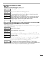
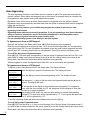
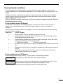
About Your Security System
Your DSC security equipment has been designed to provide you with the greatest possible flexibility
and convenience. Read this manual carefully and have your installer instruct you on your system's
operation and on which features have been implemented in your system. All users of this system
should be equally instructed in its use. Fill out the “System Information” page with all of you zone
information and access codes and store this manual in a safe place for future reference.
Fire Detection
This equipment is capable of monitoring fire detection devices such as smoke detectors and providing
a warning if a fire condition is detected. Good fire detection depends on having adequate number of
detectors placed in appropriate locations. This equipment should be installed in accordance with
N.F.P.A. standard #74. (N.F.P.A., Batterymarch Park, Quincey MA 02269). Carefully review the Family
Escape Planning guidelines in this manual.
NOTE: Your installer must enable the fire detection portion of this equipment before it becomes
functional.
Testing
To insure that your system continues to functions as intended, you must test your system weekly.
Please refer to “Testing Your System” on page 13 of this manual. If your system does not function
properly, call your installing company for service.
Monitoring
This system is capable of transmitting alarms, troubles and emergency information over telephone
lines to a monitoring station. If you inadvertently initiate an alarm, immediately call the monitoring
station to prevent an unnecessary response.
NOTE: The monitoring function must be enabled by the installer before it becomes functional.
General System Operation
Your security system is made up of a DSC control panel, one or more keypads and various sensors
and detectors. The control panel will be mounted out of the way in a utility closet or in a basement. The
metal cabinet contains the system electronics, fuses and stand-by battery. There is normally no reason
for anyone but the installer or service professional to have access to the control panel.
All the keypads have an audible indicator and command entry keys. The LED keypads have a group
of zone and system status lights. The LCD keypad has an alphanumeric liquid crystal display (LCD).
The keypad is used to send commands to the system and to display the current system status. The
keypad(s) will be mounted in a convenient location inside the protected premises close to the entry/
exit door(s).
The security system has several zones of area protection and each of these zones will be connected
to one or more sensors (motion detectors, glassbreak detectors, door contacts, etc.). A sensor in
alarm will be indicated by zone lights 1 through 6 flashing on a LED keypad or by written messages on
the LCD keypad.
IMPORTANT NOTICE
A security system cannot prevent emergencies. It is only intended to alert you and – if included –
your monitoring station of an emergency situation. Security systems are generally very reliable
but they may not work under all conditions and they are not a substitute for prudent security
practices or life and property insurance. Your security system should be installed and serviced by
qualified security professionals who should instruct you on the level of protection that has been
provided and on system operations.
1
System Information
Fill out the following information for future reference and store this manual in a safe place.
Access Codes
Your Master Code is: __________________________________________
Additional Access Codes:
2
__________________
3 ____________________
5
__________________
6 ____________________
4 ____________________
Zone Information
Zone
Protected Area
Zone Type
1
___________________________________________
_____________________________________
2
___________________________________________
_____________________________________
3
___________________________________________
_____________________________________
4
___________________________________________
_____________________________________
5
___________________________________________
_____________________________________
6
___________________________________________
_____________________________________
Keypad Zone [F] FIRE _____________________________
Keypad Zone [A] AUXILIARY _________________________________________
Keypad Zone [P] PANIC _____________________________________________
The Exit Delay Time is ________ seconds.
The Entry Delay Time is ______ seconds.
For Service
2
Monitoring Station Information:
Account #: ___________________________________
Telephone #: _________________________________
Installer Information:
Company: ___________________________________
Telephone #: _________________________________
Access Codes
Access Codes are used to arm and disarm the system. There are six access codes available: one
Master Code and five access codes.
Only the Master Code can be used to program additional security codes and to change other system
features as well as to arm and disarm the security system. The Master Code will be supplied to you by
your installer. All keypad entries are made by pressing one key at a time.
All access codes can be programmed by following the procedure outlined in “Programming Security
Codes” on page 6.
NOTE: An access code can be a four or six digit number depending on how your installer has
programmed your system. Ask your installer for more information regarding access codes.
Arming the System
Arming from an LED Keypad:
If the Ready light is ON, the system is ready for arming. If the Ready light is OFF, check to see that all
doors and windows are closed and that motion is stopped in areas covered by motion detectors. The
system cannot be armed unless the Ready light is ON indicating that all zones are closed and the
system is in the Ready state.
Enter your access code. As each digit is entered, the keypad sounder will beep. If the access code
was entered incorrectly, the keypad buzzer will sound steadily for two seconds. If this occurs, press
the [#] key and re-enter your access code. If the correct access code is entered, the keypad sounder
will beep quickly and the Armed light will come ON. Exit the premises through the door indicated by
your installer as the Exit/Entry door.
The panel will provide an exit delay period, indicated by keypad beeps, for you to exit the premises
without causing an alarm. At the end of the exit delay period, all keypad lights, except the Armed light,
will turn OFF and the system will be armed. The exit delay time can be changed by your installer.
Arming from an LCD Keypad:
When this message appears, one or more zones are not secured. To secure the
Secure System
Before Arming <> system, close all doors and windows and cease all motion in areas covered by
motion detectors.
When this message appears, use the arrow (< >) keys to verify that the system is
Enter Code to
Arm System
<> clear of troubles and that no zones are bypassed unintentionally (see “Viewing
Trouble Conditions” on page 11 and “Zone Bypassing” on page 10).
Enter Code to
Arm System
If this display is showing, the system is in the Ready state and may be fully armed.
To arm the system, enter your access code.
Exit Delay in
Progress
Once the correct access code has been entered, the display will be as shown. The
panel will provide an exit delay period, also indicated by keypad beeps, for you to
exit the premises without causing an alarm. Exit through the door indicated by your
installer as the Exit/Entry door.
Enter Code to
Disarm System
This message will be displayed once the exit delay expires and the system is fully
armed.
* WARNING *
Bypass Active
If this message appears, be aware of which zones are bypassed and why (see
“Zone Bypassing” on page 10). NOTE: If you arm the system with a zone
bypassed or with a trouble present, your security protection is reduced.
3
Alternate Arming Methods
Away Arming
Arming the system in the Away mode will have all interior zones and perimeter zones active. If motion
is detected in the interior zones, or if one of the perimeter zones is violated, the alarm sequence will
begin. To arm in the Away mode, enter your access code and exit the premises through a designated
Exit/Entry door. The system will recognise that occupants have left the premises. Once the exit delay
expires, the system will be fully armed.
Audible Exit Fault
In an attempt to reduce false alarms, the Audible Exit Fault is designed to notify you of an improper
exit when arming the system in the Away mode. In the event that you fail to exit the premises during
the allotted exit delay period, or if you do not securely close the Exit/Entry door, the system will notify
you that it was improperly armed in two ways: the keypad will emit one continuous beep and the bell or
siren will sound. If this occurs, you must re-enter the premises, enter your access code to disarm the
system, and then follow the arming procedure again, making sure to exit the premises in the proper
fashion.
Stay Arming
This feature, if enabled by your installer, will allow you to arm the perimeter zones while leaving the
interior zones inactive so that you can remain on the premises while the system is armed. When you
enter your security code to arm the system and do not exit the premises through a designated Exit/
Entry door, the system will arm in the Stay mode, automatically bypassing the interior zones.
The interior zones can be reactivated at any time by entering [✱][1] at any keypad. If you reactivate
the interior zones, be sure to only inhabit areas not covered by motion detectors. To access areas
protected by motion sensors, you must enter your security code and disarm the system.
Arming Without Entry Delay
If you wish to arm your system without the entry delay, enter [✱][9] then your access code. The Armed
light will flash as a reminder that the system is armed and has no entry delay. An entry through any
zone programmed as a delay zone will create an instant alarm.
Quick Arm
When the Quick Arm feature is enabled, the system may be armed by simply pressing [✱][0] instead
of your access code. Please note that pressing [✱][0] will only allow you to arm the system; to disarm,
you must enter a valid access code. Your installer will inform you if the Quick Arm feature has been
enabled on your system.
4
Disarming the System
Disarming from an LED Keypad:
Enter the premises through a designated Exit/Entry door; entering by any other door will sound an
immediate alarm. As soon as the Exit/Entry door is opened, the keypad will beep to indicate that the
system should be disarmed. Go to the keypad and enter your access code. If an error is made
entering the code, press the [#] key and enter your code again. As soon as the correct code is
entered, the Armed light will go out and the keypad will stop beeping.
The correct access code must be entered before the entry delay period expires. If a valid access
code is not entered during this time, the system will go into alarm. The entry time delay may be
changed by your installer.
If an alarm occurred while the system was armed, the Memory light and the zone light corresponding
to the zone which caused the alarm will flash for 30 seconds. After the 30 second period, the Memory
light and zone light will stop flashing and the panel will return to the Ready state. Pressing the [#] key
during the 30 second period will cancel the alarm memory display. To view other alarms, press [✱][3].
If a trouble was detected when the panel is disarmed, the Trouble light will turn ON (See “Viewing
Trouble Conditions” on page 11 to determine the source of the trouble.) Please note that troubles will
not display while the system is in the Alarm Memory Display mode.
Disarming from an LCD Keypad:
Upon entering through a designated Exit/Entry door, the keypad will beep and the entry delay will
commence, reminding you to disarm the system. The keypad will display the following message...
Enter your access code. If an error is made in entering the code, press the [#]
Entry Active
Enter Your Code key and enter the code again. When a valid access code is entered, the keypad
will stop beeping. If no alarms occurred while the panel was armed, and there are
no troubles, the display will read...
System Disarmed
No Alarm Memory
After about five seconds, the system will return to the Ready state and the display
will read...
Enter Code to
Arm System
View Memory <> If an alarm occurred while the system was armed, this message will be displayed.
“Zone of Alarm” Use the arrow (< >) keys to view which zones caused the alarm. If a zone is still in
alarm, the display will show the following message to indicate that a zone is open...
Secure System
Before Arming <>
Upon disarming and if a trouble is present, this message will be displayed. Use the
Enter Code to
Arm System
<> arrow (< >) keys to view which troubles are affecting the system (see “Viewing
Trouble Conditions” on page 11).
NOTE: If you return and find that an alarm has occurred while you were away, it is possible that
an intruder may still be on the premises. Go to a neighbour's house, and call the local police to
investigate.
The alarm memory is cleared each time the panel is armed so that any alarms showing are
alarms that occurred only during the last armed period.
5
If An Alarm Sounds
Fire Alarm
If your system has been installed with fire detectors and the alarm sounds in a pulsing mode, follow
your emergency evacuation plan immediately (see “Fire Escape Planning” on page 15).
Intrusion Alarm
If an intrusion alarm sounds, indicated by a continuous Bell or Siren, the alarm may be silenced by
entering your access code. If the alarm was unintentional, call local authorities immediately to avoid an
unnecessary response.
You can determine the source of the alarm by following the instructions in the “Disarming” section (see
page 4 and 5). Once the source of the alarm has been corrected, the panel can be restored to its
original Armed state.
Function Keys
(PC5506, LCD5500 and SL-75 Keypads Only)
These keypads has five function keys – marked Stay, Away, Chime, Reset and Exit – which allow easy
single-button activation of the most commonly used features. If these keys have been enabled by your
installer, you can execute their programmed function by pressing and holding the corresponding key
(keys 1-5 on the SL-75) for two seconds.
For information regarding the operation of the function keys, talk to your alarm installer.
Programming Security Codes
Programming codes from an LED Keypad:
The Master Code
To program the Master Code, enter [✱][5][current Master Code][1][new Master Code]. The Master
Code must be four digits unless otherwise indicated by your installer. Enter digits 0 through 9 only.
Press [#] to return to the Ready state.
Be sure to record your new Master Code on the “System Information” page in this booklet. NOTE: We
recommend that the factory default Master Code [1234] not be used.
Additional Codes
Up to 5 additional access codes (2 through 6) may be programmed.
To program a new code:
Enter [✱][5][Master Code][code number 2 to 6][new access code]. The code number is a single digit
from 2 to 6. Access codes must be four digits unless otherwise indicated by your installer. Enter digits
0 through 9 only. Press [#] to return to the Ready state.
If an access code already exists for the code number you have selected, it will be replaced by the new
code. Be sure to record your new code(s) on the “System Information” page in this book.
To erase a code:
Enter [✱][5][Master Code][code number 2 to 6][✱]. Press [#] to return to the Ready state. Do not erase
the Master code.
6
Programming codes from an LCD Keypad:
Master Code
Press the [✱] key to enter the function list. Scroll (< >) to...
Press (*) for <> Press [5] or [✱]. The display will read...
Access Codes
Enter Master
Access Code
(*) to Edit
User Code
Enter your current Master Code. The display will read...
<> “1P” represents the Master Code. Press the [✱] key to indicate that you wish to
1P program the Master Code. The display will read...
Enter the new Master Code. The Master Code must be four digits unless otherwise
Enter New Code
1234
<> indicated by your installer. Enter digits 0 through 9 only. Once the new code is
entered, the keypad will beep 3 times and the display will read...
(*) to Edit
User Code
<> Press [#] to exit the code programming function.
1P
Be sure to record your new Master Code on the “System Information” page in this booklet. NOTE: We
recommend that the factory default Master Code [1234] not be used.
Additional Access Codes
To erase, add or change a user code, press [✱] to enter the functions list. Use the arrow (< >) keys to
scroll to the following message...
Press (*) for <> Press [✱]. Display will read...
Access Codes
Enter Master
Access Code
[*] to Edit
User Code
Enter the Master Code. Display will read...
<> Use the scroll keys (< >) to find the access code – indicated by “2P” to “6P” – you
1P wish to add, change or delete. Press the [✱] key to select the code you wish to alter.
The display will read...
Enter New Code
1234
<> To add or change a code, enter the new code. Access codes must be four digits
unless otherwise indicated by your installer. Enter digits 0 through 9 only. To delete
an access code, enter [✱]. Once the 4 digit code or [✱] has been entered, the
keypad sounder will beep 3 times and the display will read...
[*] to Edit
User Code
<> The “P” means the code has been programmed. If there is no “P” then that code is
1P deleted. Press [#] to exit the code programming function. Do not erase the Master code.
Remember to record your new code(s) on the “System Information” page in this booklet.
7
PC1575RK LED Keypad
1
2
3
4
5
6
1
ZONE BYPASSING: Press [Θ] [1] [Zone
to be bypassed]. Press [#] to return to
“Ready”. Arm the system.
2
3
7
8
9
0
#
PROGRAMMING USER CODES: Press
[Θ] [5] [Master Code] [1 to 6 for user
code number]. Enter four digits. Press
[#] to return to “Ready”.
INSTANT ARM: Press [Θ] [9] [User
Code] to arm the system without entry
delay.
P
NOT
IN
USE
NOT
IN
USE
NOT
IN
USE
Ready
Memory
3
4
Trouble
Zone 1
Zone 2
Zone 3
1
2
3
Zone 5
A
P
Zone 6
TEST SYSTEM WEEKLY
4
7
5
6
8
9
18000031 R3
Emergency Keys (All Keypads)
PC5506 / LCD5500:
Press both * Keys for two seconds to send a FIRE
transmission.
Press both * Keys for two seconds to send an
AUXILIARY transmission.
Press both * Keys for two seconds to send a PANIC
transmission.
PC1575RK / SL-75:
Press the [F]* key for two seconds to send a FIRE
transmission.
Press the [A]* key for two seconds to send an
AUXILIARY transmission.
Press the [P]* key for two seconds to send a PANIC
transmission.
* IMPORTANT NOTE (All Keypads): The Fire,
Auxiliary and Panic keys will NOT function unless
programmed by the installer. If these keys are in
service and the installer has enabled audible
feedback, holding down the key for two seconds
will cause the keypad sounder to beep indicating
that the input has been accepted and transmission
is underway.
8
✱
✱
0
#
F
A
P
LCD5500 Keypad
Memory
1
Armed System
Zone 4
F
PC5506 LED Keypad
2
3
4
5
6
System Light (SL-75
Only):
If the System light is
ON, the system is busy
and one or more of the
conditions could be
present:
System Troubles (See
“Viewing Trouble
Conditions” on page 9).
Alarm Memory (See
“Disarming the System”
on page 5).
Zone Bypassing (See
“Zone Bypassing” on
page 8).
NOTE: If you have a SL-75 keypad, the System
light acts as a Trouble, Memory and Bypass
indicator. Unlike the other keypads, these
conditions will only be represented by the System
light. Please keep this in mind when reading other
functions in this manual.
Fire
Program
Ready
Armed
Trouble
Armed Light (All keypads):
If the Armed light is ON, the system has been armed
successfully.
Trouble Light (All keypads):
If the Trouble light is ON, see “Viewing Trouble
Conditions” on page 11.
Memory Light (LED keypads only):
Upon disarming, if an alarm has occurred while the
system was armed, the Memory light will turn ON (See
“Disarming the System” on page 5).
Ready
Stay
Stay
Away
Away
Chime
Chime
Reset
Reset
Exit
Exit
Armed
Trouble
< >
Message Display Security Station
1
4
2
5
Press to Exit / Return.
6
3
NOT IN USE
Press to select function.
NOT IN USE
NOT IN USE
TEST SYSTEM WEEKLY
Refer to Instruction Manual for
testing instructions.
Indicates more information is
available. Press either key to view.
Press to advance display to the
next function or message.
Press to see previous function or message.
NOT IN USE
Display Lights
Ready Light (All keypads):
If the Ready light is ON, the system is ready for arming.
The system cannot be armed unless the Ready light is
ON (see “Arming the System” on page 3).
Enter Code
To Arm System
Bypass
Bypass
IT
EX
A
6
T
SE
RE
F
2
5
E
IM
CH
6
1
Armed
AY
AW
5
Ready
AY
ST
4
SL-75 LED Keypad
Bypass Light (LED keypads only):
If the Bypass light is ON, one or more zones are
bypassed (See “Zone Bypassing” on page 10).
Fire Light (PC5506 keypad only):
If the Fire light is ON, a fire alarm has occurred (See
“Fire Alarm Operation” on page 13).
Program Light (PC5506 keypad only):
The Program light will flash when you are
programming access codes, or performing other
programming functions. If someone is programming
at another keypad, the Program light will turn ON to
indicate that the system is busy.
NOT IN USE
TEST SYSTEM WEEKLY
Refer to Instruction
Manual for testing
instructions.
NOT IN USE
The Liquid Crystal Display (LCD) displays prompts and
system information on two 16 character lines.
If “< >” appears, more information can be accessed by
using the arrow (< >) keys. Press [<] to see the previous
function or item of information. Press [>] to advance the
display to next function or item of information.
Press the keys on the number pad as prompted by the
LCD display to view alarms or troubles, to arm and
disarm the system and to bypass zones.
To exit a function and return to the Ready state, press [#].
To select a function press [✱].
Important Note: Test system weekly and
have any system trouble conditions
corrected by your alarm installer.
9
Zone Bypassing
The zone bypassing function is used when access is needed to part of the protected area while the
system is armed. Zones which are temporarily out of service due to damaged wiring or contacts may
be bypassed to allow system arming until repairs can be made.
Bypassed zones will not cause an alarm. Zones cannot be bypassed once the system is armed.
Bypassed zones are automatically cancelled each time the system is disarmed and must be reapplied
before the next arming.
NOTE: For security reasons, your installer may program the system to prevent you from
bypassing certain zones.
Bypassing zones reduces your security protection. If you are bypassing a zone due to damaged
wiring or contacts, please call a service technician immediately so that the problem can be
resolved and your system returned to proper working order.
Do not unintentionally bypass zones when you arm your system.
To bypass zones from an LED keypad:
Start with the system in the Ready state. Enter [✱][1][Zone number(s) to be bypassed].
Enter the zone number(s) as a single digit from 1 to 6. As each zone is bypassed, the corresponding
zone light will turn ON. If a zone is bypassed by mistake, press that zone number again and the zone
light will turn OFF, indicating that the zone is not bypassed. Press [#] to return to the Ready state.
To recall the last group of bypassed zones:
Enter [✱][1][9]. The zone lights corresponding to the last group of bypassed zones will turn ON. If you
wish to add or delete a zone from the group, press [#] to exit the viewing function and return to the
Ready state, then follow the instructions above to perform zone bypassing.
When the system is armed, the Bypass light will be ON if one or more zones are bypassed.
To bypass zones from an LCD keypad:
To bypass a zone, the system must be in the Ready state. The display will read...
Enter Code to
Arm System
Press the [✱] key to enter the functions menu. The display will read...
Press (*) for <> Press the [✱] key to enter the zone bypassing mode. The display will read...
Zone Bypass
Zone Search
“Zone Name”
<> Use the arrow (< >) keys to find the zone to be bypassed and press the [✱] key to
Zone Search
“Zone Name”
<> “B” will appear on the display to show that the zone is bypassed. To unbypass a
B zone, enter the zone number; the “B” will disappear from the display to show that
Zone Search
“Zone Name”
<> This display will be shown if a zone was open when you entered the bypassing
O command. The open zone will be represented by “O”. If you bypass the open zone,
select it. The display will read...
the zone is no longer bypassed.
the “O” will be replaced by a “B”.
To exit the bypassing mode and return to the Ready state, press the [#] key.
To recall last group of bypassed zones:
Enter [✱][1][9]. Use the arrow (< >) keys to scroll through a list of the last group of bypassed zones. If
you wish to add or delete a zone from the group, press [#] to exit the viewing function and return to the
Ready state, then follow the instructions above to perform zone bypassing.
10
Viewing Trouble Conditions
The control panel continuously monitors a number of possible trouble conditions. If one of these
trouble conditions occur, the keypad will beep twice every 10 seconds until you press any key on the
keypad.
Troubles can only be viewed when the system is in the disarmed state. If a trouble occurs while the
system is armed, enter your access code to disarm the system, then follow the procedure outlined
below to determine the specific trouble.
NOTE: A TROUBLE condition reduces the security your system is designed to provide. Call your
installing company for service.
To view troubles from an LED Keypad:
A trouble will be indicated by the Trouble light which will remain ON until the trouble condition is
cleared. If you cannot determine the cause of the trouble condition, contact your installer for
assistance.
To view the type of trouble condition, press [✱][2]. A one or more zone lights will turn ON, indicating
the various trouble conditions:
ZONE LIGHT
TYPE OF TROUBLE
1 ................. Service required. Call your installation company for service.
2 ................. Indicates the loss of AC power. When this trouble occurs, the Trouble light will turn
ON but keypad buzzer will not sound.
3 ................. Communications troubles Press [3] either or both of zone lights 1 and 2 will be ON,
indicating the following communication troubles:
1. Telephone line trouble
2. Failure to communicate
4 ................. Zone fault. Press [4] and the zone light(s) corresponding to the faulted zones will turn
ON.
5 ................. Zone tamper. Press [5] and the zone light(s) corresponding to the tampered zones will
turn ON.
6 ................. Loss of time on system clock. To set the system time, following the instructions in
“Setting System Date and Time” on page 11.
To view troubles from an LCD Keypad:
From the Ready state, use the arrow (< >) keys to scroll to the following message.
System Trouble Press [✱] [2] key to view the trouble. The message will read...
(*2) to View <>
View Trouble <> Use the arrow (< >) keys to view which troubles are present on the system. Once
“Trouble Message” you have scrolled through the list of troubles, this display will read...
Press the [#] key to exit the Trouble Viewing mode and return to the Ready state.
11
Setting the System Date and Time
To set the system time, enter [✱] [6] followed by the Master Code. Press [1]. The keypad will now
accept 10 consecutive digits:
• Enter the Time in Hours and Minutes using the 24 Hour format (00:00 to 23:59).
• Enter the Date in Months, Days and Years (MM DD YY).
Language Selection (LCD Keypads Only)
The displayed language of the keypad can be changed by pressing and holding both of the [< >]
keys simultaneously. This will cause the keypad to enter the Language Selection mode. Scroll to the
desired language and press the [✱] key. This will select the new language and restart the keypad.
Testing Your System
Alarm Test
The Alarm Test provides two second test of the keypad sounder and bell or siren. Begin with the panel
in the Ready state.
From an LED keypad, Enter [✱][6][Master Code][4] then press [#] to return to the Ready state.
From an LCD keypad, press [✱] to enter the functions list. Use the arrow (< >) keys to scroll to find
“User Functions” and press [✱] to select. Enter your Master Code and scroll to find the following
message...
Select Option <> Press [✱] to perform an Alarm Test. The keypad will display the following message...
System Test
System Test
In Progress
Press [#] to return to the Ready state.
Full System Test
We recommend that you test your system weekly. Should the system fail to function properly, call your
installation company immediately for service.
NOTE: Perform system tests during off-peak hours, such as early morning or late evening.
1. Inform the monitoring station that you are testing your system.
2. Begin with the system in the Ready state.
3. Perform a walk test.
From an LED keypad, enter [✱][6][Master Code][0]. The keypad will sound three times when the
feature is enabled.
From an LCD keypad, press [✱] to enter the functions list. Use the arrow (< >) keys to scroll to find
“User Functions” and press [✱] to select. Enter your Master Code and scroll to find the following
message.
Select Option <> Press [✱] to select. The keypad will beep three times and the display will read...
Walk Test
Walk Test
is enabled
12
4. Activate each sensor in turn (e.g. open a door/window or walk in motion detector areas).
From an LED keypad, observe the zone light turn ON when the zone is activated. The zone light will
turn OFF when the system restores to normal (i.e. door or window closed).
From an LCD keypad, the following message will be displayed when each zone is activated...
Use the arrow (< >) keys to view which zone is open. This message will
Secure System
Before Arming <> disappear when the zone is restored.
6. If the panel has any fire zones, activation will cause the alarm signal to sound in a pulsed mode.
7. Disable the walk test.
From an LED keypad, enter [✱][6][Master Code][0]. The keypad will sound one long beep when the
walk test is disabled.
From an LCD keypad, press [✱] to enter the functions list. Use the arrow (< >) keys to scroll to find
“User Functions” and press [✱] to select. Enter your Master Code and scroll to find the following
message.
Select Option <> Press [✱] to select. The keypad sound one long beep and the display will read...
Walk Test
Walk Test
is disabled
8. When testing is complete, call and advise the monitoring station.
Door Chime Feature
The door chime feature is used, while the panel is disarmed, to provide a tone from the keypad each
time a door or window is opened or closed. The doors and windows which will provide this indication
are programmed by your installer.
To activate the door chime from an LED Keypad:
Enter [✱][4] to turn the door chime feature ON and OFF. When the command is entered, the keypad
buzzer will beep 3 times if the door chime feature is enabled and will sound one long beep if it is
disabled. Press [#] to return to the Ready state.
To activate the door chime from an LCD Keypad:
Start with the panel in the disarmed mode, press [✱] to enter the function list, then scroll to find...
Press (*) For<> Press [✱] or [4] to enable or disable the Door Chime feature. Press [#] to return to
the Ready state.
Door Chime
13
Fire Alarm Operation
Alarm
On a fire alarm, the bell or siren will pulse ON and OFF. The transmission of the alarm to the monitoring
station is delayed for 30 seconds. If the alarm is not cleared within the 30 second delay, the it will be
transmitted to the monitoring station.
Silence
To silence the bell or siren, press the [#] key. If the alarm is silenced and the smoke detector is not
reset, the alarm will resound after 90 seconds.
Resetting Smoke Detectors
Once the smoke detector is reset, if it still detects smoke, the alarm sequence will resound as
described above. If there is no smoke, the system will return to normal.
To reset smoke detectors from an LED Keypad:
Press [✱][7][2].
To reset smoke detectors from an LCD Keypad:
Press [✱] to enter the function list. Scroll to find:
Press (*) For <> Press [✱] to select the output control. The display will read...
Output Control
Select Output <> Use the arrow (< >) keys to find the following message and press the [✱] key to
Utility Output
select...
Select Output <>
Sensor Reset
NOTE: If you suspect that a fire alarm has transmitted and that there is no fire condition, call the
monitoring station to avoid an unnecessary response. If a fire condition is apparent, follow your
evacuation plan immediately. If the alarm sounds at night, evacuate immediately.
NOTE: The description above may not be applicable depending on how your installer has
programmed the fire alarm operations on your system. Ask your installer for more information
regarding your system's operation.
Household Fire Safety Audit
Most fires occur in the home. To minimize this danger, we recommend that a household fire safety
audit be conducted and a fire escape plan be developed.
1. Are all electrical appliances and outlets in a safe condition? Check for frayed cords, overloaded
lighting circuits, etc. If you are uncertain about the condition of your electrical appliances or
household service, have a professional evaluate these units.
2. Are all flammable liquids stored safely in closed containers in a well ventilated cool area? Cleaning
with flammable liquids should be avoided.
3. Are fire hazardous materials (matches) well out of reach of children?
4. Are furnaces and wood burning appliances properly installed, clean and in good working order?
Have a professional evaluate these appliances.
14
Fire Escape Planning
There is often very little time between the detection of a fire and the time it becomes deadly. It is thus very
important that a family escape plan be developed and rehearsed.
1. Every family member should participate in developing the escape plan.
2. Study the possible escape routes from each location within the house. Since many fires occur at night,
special attention should be given to the escape routes from sleeping quarters.
3. Escape from a bedroom must be possible without opening the interior door.
Consider the following when making your escape plans:
• Make sure that all perimeter doors and windows are easily opened. Ensure that they are not painted
shut, and that their locking mechanisms operate smoothly.
• If opening or using the exit is too difficult for children, the elderly or handicapped, plans for rescue
should be developed. This includes making sure that those who are to perform the rescue can
promptly hear the fire warning signal.
• If the exit is above the ground level, an approved fire ladder or rope should be provided as well as
training in its use.
• Exits on the ground level should be kept clear. Be sure to remove snow from exterior patio doors in
winter; outdoor furniture or equipment should not block exits.
• Each person should know of a predetermined assembly point where everyone can be accounted for
i.e.: across the street or at a neighbour's house. Once everyone is out of the building, call the Fire
Department.
• A good plan emphasizes quick escape. Do not investigate or attempt to fight the fire, and do not
gather belongings or pets as this wastes valuable time. Once outside, do not re-enter the house.
Wait for the fire department.
• Write the fire escape plan down and rehearse it frequently so that should an emergency arise,
everyone will know what to do. Revise the plan as conditions change, such as the number of people
in the home, or if there are changes to the building's construction.
• Make sure your fire warning system is operational by conducting weekly tests (see “Fire Alarm
Operation” on page ??). If you are unsure about system operation, contact your installing dealer.
• We recommend that you contact your local fire department and request further information on fire
safety and escape planning. If available, have your local fire prevention officer conduct an in-house
fire safety inspection.
Maintenance
With normal use, the system requires minimum maintenance. The following points should be observed.
1. Do not wash the security station with a wet cloth. Light dusting with a slightly moistened cloth should
remove normal accumulations of dust.
2. The battery/ bell test is designed to determine battery condition. We recommended, however, that the
stand-by batteries be replaced every three years.
3. For other system devices such as smoke detectors, passive infrared, ultrasonic or microwave motion
detectors or glassbreak detectors, consult the respective manufacturer’s literature for testing and
maintenance.
15
Limited Warranty
Digital Security Controls Ltd. warrants that for a period of twelve months from the date of purchase, the
product shall be free of defect in materials and workmanship under normal use and that in fulfilment of
any breach of such warranty, Digital Security Controls Ltd. shall, at its option, repair or replace the
defective equipment upon return of the equipment to its repair depot. This warranty applies only to
defects in parts and workmanship and not to damage incurred in shipping or handling, or damage due
to causes beyond the control of Digital Security Controls Ltd. such as lightning, excessive voltage,
mechanical shock, water damage, or damage arising out of abuse, alteration or improper application
of the equipment.
The foregoing warranty shall apply only to the original buyer, and is and shall be in lieu of any and all
other warranties, whether expressed or implied and of all other obligations or liabilities on the part of
Digital Security Controls Ltd. This warranty contains the entire warranty. Digital Security Controls Ltd.
neither assumes, nor authorizes any other person purporting to act on its behalf to modify or to change
this warranty, nor to assume for it any other warranty or liability concerning this product.
In no event shall Digital Security Controls Ltd. be liable for any direct, indirect or consequential
damages, loss of anticipated profits, loss of time or any other losses incurred by the buyer in
connection with the purchase, installation or operation or failure of this product.
WARNING: Digital Security Controls Ltd. recommends that the entire system be completely
tested on a regular basis. However, despite frequent testing, and due to, but not limited to,
criminal tampering or electrical disruption, it is possible for this product to fail to perform as
expected.
16
Instruction
Manual
PC158O
© 1997 Digital Security Controls Ltd.
Printed in Canada
29000467 R2
Instruction
Manual
PC158O
© 1997 Digital Security Controls Ltd.
Printed in Canada
29000467 R2
AVIS: L’étiquette de l’Industrie Canada identifie le matériel homologué. Cette étiquette certifie que le matériel est conforme à
certaines normes de protection, d’exploitation et de sécurité des réseaux de télécommunications. Industrie Canada n’assure
toutefois pas que le matériel fonctionnera à la satisfaction de l’utilisateur.
Avant d’installer ce matériel, l’utilisateur doit s’assurer qu’il est permis de le raccorder aux installations de l’entreprise locale de
télécommunication. Le matériel doit également être installé en suivant une méthode acceptée de raccordement. L’abonné ne
doit pas oublier qu’il est possible que la conformité aux conditions énoncées ci-dessus n’empêchent pas la dégradation du
service dans certaines situations.
Les réparations de matériel homologué doivent être effectuées par un centre d’entretien canadien autorisé désigné par le
fournisseur. La compagnie de télécommunications peut demander à l’utilisateur de débrancher un appareil à la suite de
réparations ou de modifications effectuées par l’utilisateur ou à cause de mauvais fonctionnement.
Pour sa propre protection, l’utilisateur doit s’assurer que tous les fils de mise à la terre de la source d’énergie électrique, les lignes
téléphoniques et les canalisations d’eau métalliques, s’il y en a, sont raccordés ensemble. Cette précaution est particulièrement
importante dans les régions rurales.
AVERTISSEMENT: L’utilisateur ne doit pas tenter de faire ces raccordements lui-même; il doit avoir recours à un service
d’inspection des installations électriques, ou à un électricien, selon le cas.
L’indice de charge (IC) assigné a chaque dispositif terminal indique, pour éviter toute surcharge, le pourcentage de la charge
totale qui peut être raccordée à un circuit téléphonique bouclé utilisé par ce dispositif. La terminaison du circuit bouclé peut être
constituée de n’importe quelle combinaison de dispositifs, pourvu que la somme des indices de charge de l’ensemble des
dispositifs ne dépasse pas 100.
L’Indice de charge de ce produit est 2.
NOTICE: The Industry Canada label identifies certified equipment. This certification means that the equipment meets certain
telecommunications network protective, operational and safety requirements. Industry Canada does not guarantee the
equipment will operate to the user’s satisfaction.
Before installing this equipment, users should ensure that it is permissible to be connected to the facilities of the local
telecommunications company. The equipment must also be installed using an acceptable method of connection. The customer
should be aware that compliance with the above conditions may not prevent degradation of service in some situations.
Repairs to certified equipment should be made by an authorized Canadian maintenance facility designated by the supplier. Any
repairs or alterations made by the user to this equipment, or equipment malfunctions, may give the telecommunications company
cause to request the user to disconnect the equipment.
User should ensure for their own protection that the electrical ground connections of the power utility, telephone lines and internal
metallic water pipe system, if present, are connected together. This precaution may be particularly important in rural areas.
CAUTION: Users should not attempt to make such connections themselves, but should contact the appropriate electric
inspection authority, or electrician, as appropriate.
The Load Number (LN) assigned to each terminal device denotes the percentage of the total load to be connected to a telephone
loop which is used by the device, to prevent overloading. The termination on a loop may consist of any combination of devices
subject only to the requirement that the total of the Load Numbers of all the devices does not exceed 100.
The Load Number of this unit is 2.
FCC COMPLIANCE STATEMENT
CAUTION: Changes or modifications not expressly approved by Digital Security Controls Ltd. could void your authority to use this equipment.
This equipment has been tested and found to comply with the limits for a Class B digital device, pursuant to Part 15 of the FCC Rules. These limits
are designed to provide reasonable protection against harmful interference in a residential installation. This equipment generates, uses and can
radiate radio frequency energy and, if not installed and used in accordance with the instructions, may cause harmful interference to radio
communications. However, there is no guarantee that interference will not occur in a particular installation. If this equipment does cause harmful
interference to radio or television reception, which can be determined by turning the equipment off and on, the user is encouraged to try to correct the
interference by one or more of the following measures:
• Re-orient the receiving antenna.
• Increase the separation between the equipment and receiver.
• Connect the equipment into an outlet on a circuit different from that to which the receiver is connected.
• Consult the dealer or an experienced radio/television technician for help.
The user may find the following booklet prepared by the FCC useful: “How to Identify and Resolve Radio/Television Interference Problems”. This
booklet is available from the U.S. Government Printing Office, Washington D.C. 20402, Stock # 004-000-00345-4.
IMPORTANT INFORMATION
This equipment complies with Part 68 of the FCC Rules. On the side of this equipment is a label that contains, among other information, the FCC
registration number of this equipment.
NOTIFICATION TO TELEPHONE COMPANY Upon request, the customer shall notify the telephone company of the particular line to which
the connection will be made, and provide the FCC registration number and the ringer equivalence of the protective circuit.
FCC Registration Number: F53CAN-30220-AL-E
Ringer Equivalence Number: 0.1B
USOC Jack: RJ-31X
TELEPHONE CONNECTION REQUIREMENTS Except for the telephone company provided ringers, all connections to the telephone
network shall be made through standard plugs and telephone company provided jacks, or equivalent, in such a manner as to allow for easy,
immediate disconnection of the terminal equipment. Standard jacks shall be so arranged that, if the plug connected thereto is withdrawn, no
interference to the operation of the equipment at the customer’s premises which remains connected to the telephone network shall occur by
reason of such withdrawal.
INCIDENCE OF HARM Should terminal equipment or protective circuitry cause harm to the telephone network, the telephone company shall,
where practicable, notify the customer that temporary disconnection of service may be required; however, where prior notice is not practicable,
the telephone company may temporarily discontinue service if such action is deemed reasonable in the circumstances. In the case of such
temporary discontinuance, the telephone company shall promptly notify the customer and will be given the opportunity to correct the situation.
ADDITIONAL TELEPHONE COMPANY INFORMATION The security control panel must be properly connected to the telephone line with a
USOC RJ-31X telephone jack.
The FCC prohibits customer-provided terminal equipment be connected to party lines or to be used in conjunction with coin telephone service. Interconnect rules may vary from state to state.
CHANGES IN TELEPHONE COMPANY EQUIPMENT OR FACILITIES The telephone company may make changes in its communications
facilities, equipment, operations or procedures, where such actions are reasonably required and proper in its business. Should any such changes
render the customer’s terminal equipment incompatible with the telephone company facilities the customer shall be given adequate notice to the
effect modifications to maintain uninterrupted service.
RINGER EQUIVALENCE NUMBER (REN) The REN is useful to determine the quantity of devices that you may connect to your telephone line
and still have all of those devices ring when your telephone number is called. In most, but not all areas, the sum of the RENs of all devices connected
to one line should not exceed five (5.0). To be certain of the number of devices that you may connect to your line, you may want to contact your local
telephone company.
EQUIPMENT MAINTENANCE FACILITY If you experience trouble with this telephone equipment, please contact the facility indicated below
for information on obtaining service or repairs. The telephone company may ask that you disconnect this equipment from the network until the
problem has been corrected or until you are sure that the equipment is not malfunctioning.
Digital Security Controls Ltd. 160 Washburn St., Lockport, NY 14094