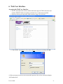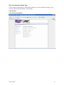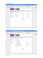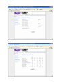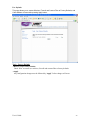
1
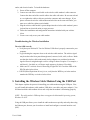
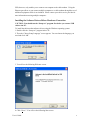
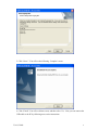
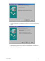
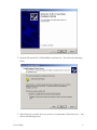
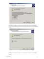
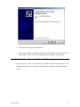
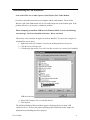
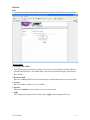
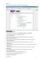
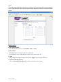
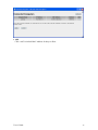
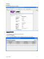
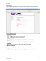
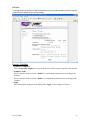
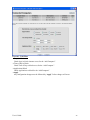
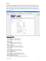
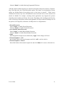
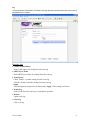
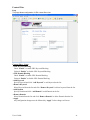
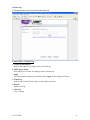
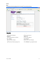
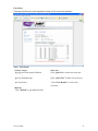
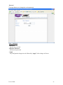
Wireless LAN Cable Modem Modem Number: U10C007 User’s Guide Rev. 1.1 Firmware 5.11.1117 September 17Th, 2004 Contents 1. BEFORE YOU BEGIN ...........................................................................................................4 Understand the Wireless Cable Modem’s Features .......................................................................................... 4 Contact Your Local Cable Operator................................................................................................................... 4 Prepare Your Area for Wireless Cable Modem Installation ............................................................................ 5 Gather Supplied and Required Items ................................................................................................................. 5 2. INSTALLING THE MODEM USING WIRELESS.............................................................6 Installing the Hardware ....................................................................................................................................... 6 Troubleshooting the Wireless Installation.......................................................................................................... 7 3. INSTALLING THE WIRELESS CABLE MODEM USING THE USB PORT...............7 Installing the Hardware ..................................................................................................................................... 10 Installing the Software Drivers.......................................................................................................................... 10 Installing the Software Drivers in Windows 98 SE Operating System......................................................... 10 Installing the Software Drivers in Windows Me Operating System ............................................................. 14 Installing the Software Drivers in Windows 2000 Operating System........................................................... 16 Installing the Software Drivers in Windows XP Operating System.............................................................. 19 Troubleshooting the USB Installation............................................................................................................... 21 Uninstalling the USB Driver .............................................................................................................................. 22 4. INSTALLING THE MODEM USING THE ETHERNET PORT...................................22 Installing the Hardware ..................................................................................................................................... 23 Troubleshooting the Ethernet Installation ....................................................................................................... 23 5. WIRELESS CABLE MODEM LEDS AND CONNECTORS .........................................24 LEDs on the Front of the Modem ..................................................................................................................... 25 Connectors on the Back of the Modem............................................................................................................. 25 6. WEB USER INTERFACE ...................................................................................................27 Accessing the Web User Interface ..................................................................................................................... 27 Web User Interface Home Page......................................................................................................................... 28 Cable Modem....................................................................................................................................................... 28 User’s Guide 2 Cable Modem Information ................................................................................................................... 28 Cable Modem Status.............................................................................................................................. 29 Downstream............................................................................................................................................ 29 Upstream ................................................................................................................................................ 30 Upstream Burst...................................................................................................................................... 30 Operation Configuration....................................................................................................................... 31 Event Log................................................................................................................................................ 31 Wireless ................................................................................................................................................................ 32 Basic ........................................................................................................................................................ 32 Security.................................................................................................................................................... 33 Access ...................................................................................................................................................... 35 Gateway................................................................................................................................................................ 37 Information ............................................................................................................................................. 37 Firewall................................................................................................................................................................. 38 Time Provision ........................................................................................................................................ 38 TOD filter ................................................................................................................................................ 39 Web filter ................................................................................................................................................. 41 Log........................................................................................................................................................... 43 Content Filter ...................................................................................................................................................... 44 Setup........................................................................................................................................................ 44 Violation Log........................................................................................................................................... 45 Tools ...................................................................................................................................................................... 46 Ping ......................................................................................................................................................... 46 Trace Route ............................................................................................................................................. 47 Client List ................................................................................................................................................ 48 Password ................................................................................................................................................. 49 User Defaults........................................................................................................................................... 50 User’s Guide 3 1. Before You Begin Your new wireless cable modem provides high-speed wireless access to the Internet by using IEEE 802.11b/g wireless standard and an active Internet Connection through your cable service provider. This user guide describes how to set up and use the wireless cable modem. Before installing the wireless cable modem, you should read this user guide to ensure proper wireless cable modem operation. Understand the Wireless Cable Modem’s Features Your wireless cable modem has the following features to help you access and use the Internet: • Wireless connectivity means that you can use your PC just about anywhere in your home. • • 802.11b/g compliance ensures interoperability with other 802.11b/g compliant devices Your wireless cable modem supports transmission rates of 54, 48, 36, 24, 18, 12, 11, 9, 6, 5.5, 2, and 1 Mbps. . • Two-way design allows the wireless cable modem to send and receive data over the cable television network. • Cable bandwidth allows data rates of up to 38 megabits per second (Mbps)*, which is faster than analog modems, integrated services digital network (ISDN), or asymmetric digital subscriber line (ADSL). • Using your cable line means that the wireless cable modem is always on, always connected, and doesn’t tie up your phone line. • Plug-and-play operation through universal serial bus (USB) ensures easy setup and installation. • Data Over Cable Service Interface Specification (DOCSIS) compliance ensures interoperability with DOCSIS compliant cable operators. *NOTE: Speeds may vary based on the following factors: • • • • Computer equipment including available RAM and processor speed Software applications utilizing your computer’s resources Network traffic depending on the time of day Limitations set by your Cable Service Provider Contact Your Local Cable Operator Before installing you new wireless cable modem, you must contact your local cable service provider to activate your Internet account. Be sure to have the wireless cable modem’s MAC address available, which can be found on the underside of the wireless cable modem. User’s Guide 4 Prepare Your Area for Wireless Cable Modem Installation Before installing your wireless cable modem, you should first prepare your area. To do this: 1. Locate your cable outlet and ensure that it is located within proper distance of your wireless cable modem and computer. Be sure not to bend the cable as this may strain the connector and cause damage. 2. Place wireless cable modem as high as possible. Allow sufficient airflow around the wireless cable modem to prevent overheating. 3. Place wireless cable modem and wireless clients in open areas or far away from transformers, heavy-duty motors, microware ovens, refrigerators, fluorescent lights, and other manufacturing equipment. 4. Ensure that the temperature in the room where the wireless cable modem will be operating is between 0 and 40°C (32 and 104°F) 5. The wireless signal may be weaker after it has passed through metal, concrete, brick, walls, or floors. Also, make sure that the wireless cable modem and wireless adapters are positioned so that the signal will travel straight through a wall or ceiling for better reception. For example, a wall that is 1 foot thick, at a 45-degree angle appears to be almost 2 feet thick. Gather Supplied and Required Items You will use a variety of items to install your wireless cable modem. Some of the items are supplied with your wireless cable modem. Supplied Verify that these items were included in the cable modem’s package: • • • • Wireless cable modem Power adapter USB cable (1.5m) Ethernet cable (1.8m) • CD containing USB drivers, wireless client drivers, and this user guide Not Supplied Verify that these items are available before beginning the installation: • If using the wireless cable modem’s USB port: o A PC running Windows 98 Second Edition (SE), Windows Me, Windows 2000, or Windows XP. The cable modem’s USB setup does not support the Macintosh operating system, Windows 98 First Edition, and NT. o Windows 98 SE, Windows Me, Windows 2000, or Windows XP CD or diskettes. o An active USB port on your PC. User’s Guide 5 • If using the wireless cable modem’s Ethernet port: o A PC running Windows 95 (or later) operating system or a Macintosh computer running system 7.6 (or later) operating system o An active Ethernet port on your PC or Macintosh • If using the wireless cable modem’s Wireless feature: o A PC running Windows 98 (or later) operating system or a Macintosh computer running system 7.6 (or later) operating system o An active wireless client on your PC or Macintosh Be sure to follow the instructions provided for the port that you want to use. Using the Wireless feature of your wireless cable modem is the simplest and quickest way to connect your PC or MAC to the Internet. All you need is an 802.11b/g wireless client that is connected to your PC or MAC. Depending on your cable service provider, you may be able to connect multiple wireless clients to your wireless cable modem. Using the USB port allows you to install the wireless cable modem more quickly and easily than using the Ethernet port, because you do not have to install and configure a network interface card (NIC). USB, however, only enables you to connect one computer to the wireless cable modem. Using the Ethernet port allows you connect multiple computers to a wireless cable modem through the use of additional equipment which is not included. Please contact your cable service provider for more information on using multiple computers. Chapter 2 provides instructions for installing your wireless cable modem using the Wireless feature. Chapter 3 provides instructions for installing your wireless cable modem using the USB port. Chapter 4 provides instructions for installing your wireless cable modem using the Ethernet port. 2. Installing the Modem Using Wireless This chapter explains the process for installing your wireless cable modem using the wireless feature. First you will install the hardware (wireless cable modem, wireless client (not included), coax cable (not included), and power adapter). Installing the Hardware This section explains how to connect the wireless cable modem to the computer, wall cable User’s Guide 6 outlet, and electrical outlet. To install the hardware: 1. Power off the computer 2. Connect one end of the coaxial cable to the wireless cable modem’s cable connector. Connect the other end of the coaxial cable to the cable wall outlet. Be sure not to bend or over tighten the cables as this may strain the connector and cause damage. If you plan to connect the wireless cable modem and television to the same wall outlet, you must use a cable line splitter (not included). 3. Plug the wireless cable modem’s power adapter into the wireless cable modem’s power jack and into an electrical outlet or surge protector. 4. Follow the installation and configuration instructions included with your wireless client. 5. You are now ready to use your cable modem. Troubleshooting the Wireless Installation The wlan LED is not lit. • Verify that your Wireless PC Card or Wireless USB client is properly connected to your computer. • Try positioning the computer closer to the wireless cable modem. The wireless signal may be weaker after it has passed through metal, concrete, brick, walls, or floors. Make sure that the wireless cable modem and wireless adapters are positioned so that the signal will travel straight through a wall or ceiling for better reception. For example, a wall that is 1 foot thick, at a 45-degree angle appears to be almost 2 feet thick. • Make sure PC's wireless client is connecting to right WLCM. Check the SSID of the WLCM and wireless client. • If WEP (Wired Equivalent Privacy) is set, verify that the WEP key set in the modem matches the WEP key set in the wireless client 3. Installing the Wireless Cable Modem Using the USB Port This chapter explains the process for installing your cable modem using the USB port. First, you will install the hardware (cable modem, USB cable, coax cable, and power adapter). You will then install the cable modem drivers and verify that the modem is functioning properly. NOTE: The cable modem’s USB setup does not support the Macintosh operating system, Windows 95 & NT. Using the USB port allows you to install the cable modem more quickly and easily than using the Ethernet port, because you do not have to install and configure a network interface card (NIC). User’s Guide 7 USB, however, only enables you to connect one computer to the cable modem. Using the Ethernet port allows to you connect multiple computers to a cable modem through the use of additional equipment which is not included. Please contact your cable service provider for more information on using multiple computers. Installing the Software Drivers Before Hardware Connection CAUTION: You should run the “Setup.exe” program first before you connect USB cable to the PC. To install the cable modem software drivers using the Windows operating system: 1. Double click the “Setup.exe” program in the CD. 2. Then the “Choose Setup Language” screen appears. You can choose the language you need and click “OK”. 3. You will see the following Welcome screen. 4. Click “Next>”. You will see the following Start screen. User’s Guide 8 5. Click “Next>”. You will see the following ‘Complete’ screen. 6. Click “Finish”. You will see below screen, and then select ‘Yes.’ Now you can connect the USB cable to the PC by following next section instructions. User’s Guide 9 Installing the Hardware This section explains how to connect the cable modem to the computer, wall outlet, and electrical outlet. To install the hardware: 1. Power off the computer 2. Connect one end of the coaxial cable to the cable modem’s cable connector. Connect the other end of the coaxial cable to the cable wall outlet. Be sure not to bend or over tighten the cables as this may strain the connector and cause damage. If you plan to connect the cable modem and television to the same wall outlet, you must use a cable line splitter (not included). 3. Connect one end of the USB cable to the cable modem’s USB port and the other end of the cable to the USB port on the PC. 4. Plug the cable modem’s power adapter into the cable modem’s power jack and into a wall outlet or surge protector. 5. You are now ready to install the software drivers. Installing the Software Drivers This section explains how to install the software drivers that your PC requires for the cable modem to operate. Installing the Software Drivers in Windows 98 SE Operating System CAUTION: You must install the drivers located on the CD that ships with your cable modem. If you use the default Windows-supplied software drivers, you will not be able to properly install the cable modem. To install the cable modem software drivers using the Windows 98 operating system: 1. Power on your PC. After your computer boots, Windows detects the cable modem. The Found New Hardware screen appears, followed by the Add New Hardware Wizard screen. User’s Guide 10 2. Insert the CD into the PC’s CD-ROM drive and click Next. You will see the following screen: 3. Select Search for the best driver for your device (Recommended). Then select Next. You will see the following screen. User’s Guide 11 4. Check the CD-ROM drive check box and verify that the CD is in the CD-ROM drive. Click Next to have Windows search for the necessary driver files. You will see the following. CAUTION: You must verify that Ambit USB Cable Modem appears on the screen. If USB Composite Device appears, you must click Back twice and specify the correct location of the driver files. DO NOT proceed if USB Composite Device is displayed in the above window. Contact your cable provider for further assistance. 5. Click Next. The computer automatically installs the necessary driver files. You may see the following screen User’s Guide 12 6. If the above screen appears, you must insert the Windows 98 CD so that Windows can copy the remaining files. 7. Wait for Windows to complete copying the remaining files. User’s Guide 13 8. Click Finish to complete the installation. You will see the following screen. 9. Choose Yes to restart your computer. 10. After the computer is rebooted, verify that the USB LED is lit on the front of you cable modem. If not, refer to the troubleshooting section later in this chapter. Installing the Software Drivers in Windows Me Operating System To install the cable modem software drivers using the Windows Me operating system: 1. Power on your PC. After your computer boots, Windows detects the cable modem. The Found New Hardware screen appears, followed by the Found New Hardware Wizard screen. 2. Insert the CD into the PC’s CD-ROM and click Next. You will see the following screen. User’s Guide 14 3. Select Automatic search for a better driver (Recommended) and click (Next). The computer automatically copies the necessary driver files from the CD. You will see the following screen. 4. Check the CD-ROM drive check box and verify that the CD is in the CD-ROM drive. Click Next to have Windows search for the necessary driver files. You will see the following User’s Guide 15 5. Click Finish after the computer has copied the necessary files. You will see the following screen. 6. Click Yes to restart the computer Installing the Software Drivers in Windows 2000 Operating System To install the cable modem software drivers using the Windows 2000 operating system: 1. Power on your PC. After your computer boots, Windows detects the cable modem. The Found New Hardware screen appears, followed by the Found New Hardware Wizard screen. User’s Guide 16 2. Insert the CD into the PC’s CD-ROM Drive and click Next. You will see the following screen. 3. Select Search for a suitable driver for my device (recommended. Then select Next>. You will see the following screen User’s Guide 17 4. Check the CD-ROM drive check box and verify that the CD is in the CD-ROM drive. Click Next to have Windows locate the necessary driver files. You will see the following screen. 5. Click Next to install the driver files for the cable modem. You will see the following screen. User’s Guide 18 7. Click Finish to complete the installation. 8. After the installation is completed, verify that the USB LED is lit on the front of you cable modem. If not, refer to the troubleshooting section later in this chapter. Installing the Software Drivers in Windows XP Operating System 1. Power on your PC. After your computer boots, Windows detects the cable modem. The Found New Hardware screen appears, followed by the Found New Hardware Wizard screen. User’s Guide 19 2. Choose the software automatically (Recommended). Click Next to continue. You will see the following screen. 3. Click Finish to complete the installation. User’s Guide 20 Troubleshooting the USB Installation None of the LEDs are on when I power on the Wireless LAN Cable Modem. Check the connection between the power adapter and the cable modem. Power off the Wireless LAN Cable Modem and wait for 5 Seconds and power on the modem again. If the problem still exists, you may have a hardware problem. When attempting to install the USB driver in Windows 98 SE, I receive the following error message: Device not installed at this time. Driver not found. This usually occurs when the wrong driver has been installed. To remove the wrong driver and install the correct driver: 1. Right-click on the My Computer icon on your desktop and choose Properties. 2. Click the Device Manager tab 3. Click the plus sign next to Universal Serial Bus controllers to view the list of installed USB device drivers 4. Select USB Composite Device and click Remove 5. Click Refresh The Add New Hardware Wizard window appears, displaying the device name USB Composite Device. Refer to the proper operating system instructions in this chapter for information on reinstalling the driver properly. User’s Guide 21 All of the LEDs on the front of my modem look correct, but I cannot access the Internet. • If the POWER, USB, SYNC, and READY are solidly lit, the cable modem is working properly. Use the following procedures to verify connectivity between the PC and the cable modem: o Launch Your PC’s Internet Browser (e.g., Netscape, IE) o Enter http://192.168.100.1 into your browser. This URL connects you directly to the web server within your cable modem. A successful connection indicates that the PC is able to communicate with the cable modem. The next step is to enter a public URL to ensure connectivity between the cable modem and your cable service provider. If this fails, please contact your cable service provider for further assistance. • Try restarting the computer so that it could re-establish a connection with the cable modem. • Power cycle the cable modem by removing the power adapter from the electrical outlet and plugging it back in. Wait several minutes for the cable modem to re-establish communications with your cable service provider. • Remove any other USB devices from your computer and connect the cable modem’s USB cable directly to the USB port on your computer. • If you are using a cable splitter, try removing the splitter and connect the cable modem directly to the cable wall outlet. Wait several minutes for the cable modem to re-establish communications with your cable service provider. • • Your USB or coaxial cable may be damaged. Try using another cable. If none of these suggestions work, contact your cable service provider for further assistance. Uninstalling the USB Driver 1. Insert the supplied CD into your CD-ROM drive 2. Click on the My Computer icon on your desktop. Then click on the icon that belongs to your CD-ROM Drive. Locate the file called “setup.exe” and click on the file. This program will remove all the necessary files from you computer. 4. Installing the Modem Using the Ethernet Port This chapter explains the process for installing your wireless cable modem using the Ethernet port. Using the Ethernet port allows to you connect multiple computers to a wireless cable modem through the use of additional equipment which is not included. Please contact your cable service provider for more information on using multiple computers. See Chapter 2 “Installing the Wireless Cable Modem Using the USB Port” for instructions on User’s Guide 22 installing the wireless cable modem using the USB port. You can use the wireless cable modem’s Ethernet port if you have: • A PC running Windows 95 (or later) operating system or a Macintosh computer running system 7.6 (or later) operating system • An active Ethernet port on your PC Before you begin, verify that your Network Interface Card (NIC) has been installed and configured for use with your wireless cable modem. The wireless cable modem requires TCP/IP to be installed. Contact your cable service provider for assistance with installing and configuring TCP/IP. After installed the hardware, your computer can connect the wireless cable modem directly by using Network Interface Card. Unlike USB installation, there is no needed for software installation for the Ethernet connection. Installing the Hardware This section explains how to connect the wireless cable modem to the computer, wall cable outlet, and electrical outlet. To install the hardware: 1. Power off the computer 2. Connect one end of the coaxial cable to the wireless cable modem’s cable connector. Connect the other end of the coaxial cable to the cable wall outlet. Be sure not to bend or over tighten the cables as this may strain the connector and cause damage. If you plan to connect the wireless cable modem and television to the same wall outlet, you must use a cable line splitter (not included). 3. Connect one end of the Ethernet cable to the wireless cable modem’s Ethernet port and the other end of the cable to the Ethernet port on the PC or network interface card (NIC). 4. Plug the wireless cable modem’s power adapter into the wireless cable modem’s power jack and into a wall outlet or surge protector. 5. If the pwr, sync, ready, and ethernet LEDs are solidly lit, the wireless cable modem is working properly. Troubleshooting the Ethernet Installation None of the LEDs are on when I power on the Wireless LAN Cable Modem. Check the connection between the power adapter and the cable modem. Power off the Wireless LAN Cable Modem and wait for 5 seconds and power on the modem again. If the problem still exists, you may have a hardware problem. The ethernet 1 or 2 or 3 or 4 LED on my wireless cable modem is not lit. User’s Guide 23 • Try restarting the computer so that is could re-establish a connection with the wireless cable modem. • Check for a resource conflict (Windows users only). To do this: 1) Right-click on the My Computer icon on your desktop and choose Properties. 2) Click the Device Manager tab and look for a yellow exclamation point or red X over the NIC in the Network Adapters field. If you see either one, you may have an IRQ conflict. Refer to the manufacturer’s documentation or you cable service provider for further assistance. • Verify that TCP/IP is the default protocol for your network interface card (NIC) • Power cycle the wireless cable modem by removing the power adapter from the electrical outlet and plugging it back in. Wait several minutes for the wireless cable modem to re-establish communications with your cable service provider. • Your Ethernet cable may be damaged. Try another cable. All of the LEDs on the front of my modem look correct, but I cannot access the Internet. • If the pwr, sync, and ready LEDs are solidly lit, the wireless cable modem is working properly. Try restarting the computer so that is could re-establish a connection with the wireless cable modem. • Power cycle the wireless cable modem by removing the power adapter from the electrical outlet and plugging it back in. Wait several minutes for the wireless cable modem to re-establish communications with your cable service provider. • If your PC is connected to a hub or gateway, try connecting the PC directly into the wireless cable modem. • If you are using a cable splitter, try removing the splitter and connect the wireless cable modem directly to the cable wall outlet. Wait several minutes for the wireless cable modem to re-establish communications with your cable service provider. • • Your Ethernet or coaxial cable may be damaged. Try using another cable. If none of these suggestions work, contact your cable service provider for further assistance. 5. Wireless Cable Modem LEDs and Connectors This chapter describes the functions of the wireless cable modem’s LEDs and connectors. When the pwr, sync, and ready LEDs are lit, the wireless cable modem is working properly. The usb or enet 1, 2, 3, 4 LEDs should also be lit depending on what port is being used. The following provides an overview of the LED indicator lights on the front of the wireless cable modem and what the LEDs mean. User’s Guide 24 LEDs on the Front of the Modem pwr usb _____Ethernet____ sync ready wlan 1 2 3 4 • pwr: Indicates that the wireless cable modem has successfully completed internal power-on tests. • usb: Indicates connectivity between the USB port on the wireless cable modem and a PC’s USB port. • sync: Indicates the connection status between the wireless cable modem and the cable network. The LED is lit when the wireless cable modem has established a downstream channel with the cable service provider’s Cable Modem Termination System (CMTS). • ready: Indicates that the wireless cable modem has completed the ranging/registration process and is ready to send/receive data. • wlan: Indicates that at least one wireless client is linked to the wireless cable modem. • Enet 1, 2, 3, 4: Indicates connectivity between the Ethernet port on the wireless cable modem and the Ethernet port on a PC or Mac. This LED blinks when the wireless cable modem is transferring or receiving data over the Ethernet cable. Installation problems with the wireless cable modem are commonly due to the cable network and its topography. LEDs on the front panel of the wireless cable modem reveal operational status and help you determine problem areas. Connectors on the Back of the Modem This list of connectors describes where to connect the cables and power adapter when installing the wireless cable modem. User’s Guide 25 Ethernet 10/100 PWR 4 3 2 1 USB Cable 1. PWR: This is where you plug the included power adapter. Remember to use only the power adapter that came with the wireless cable modem. 2. Ethernet 10/100 Port 1, 2, 3, 4: This is where you plug the Ethernet cable. The other end connects to the Ethernet port on the PC or NIC 3. USB Port: This is where you plug the included USB cable. The other end connects to the USB port on your PC. 4. Cable Connector: This is where you connect the coaxial cable (not included) that leads to the cable splitter (not included) or the cable wall outlet. User’s Guide 26 6. Web User Interface Accessing the Web User Interface 1. The PC connected to the wireless cable modem must support TCP/IP connection and dynamic DHCP IP address acquisition, and must have a web browser installed. 2. Open the web browser and set the URL location as: http://192.168.100.1 3. Click LOGIN. Input user for User name and user for Password, and then click OK. 4. If the user inputs an incorrect user name and/or password, the web user interface displays “401Unauthorized”. User’s Guide 27 Web User Interface Home Page A main menu is shown at the top of the pages and the user can select different options to view wireless cable modem information.. They include: Cable Modem Cable Modem Information User’s Guide 28 Cable Modem Status Downstream User’s Guide 29 Upstream Upstream Burst User’s Guide 30 Operation Configuration Event Log User’s Guide 31 Wireless Basic This page allows configuration of the Wireless Modem parameters the SSID and channel number. Wireless Basic • Network Name (SSID) Enter SSID to group your wireless network. The wireless clients that have the same SSID can communicate with others. The default SSID is the last four hexadecimal digits of the modem MAC address. • Broadcast SSID When set to closed, SSID will not be broadcasted to avoid unauthorized access to the network. • Country When set to USA, Channel 1 to 11 is available. • Interface When set to enabled, wireless clients can access to the network. • Apply Any configuration changes must be followed by “Apply” before changes will occur. User’s Guide 32 Security This page allows configuration of the WEP keys and/or passphrase. Wireless Security • Network Authentication Network authentication can be set to disable, 802.1x, WPA, and WPA-PSK. Factory default for Network Authentication is disabled. • WPA Pre-Shared Key Enter WPA Pre-shared Key when WPA-PSK network authentication is selected. • WPA Group Rekey Interval Enter WPA Group Rekey Interval when WPA-PSK network authentication is selected. • WPA Pre-Shared Key Enter WPA Pre-shared Key when WPA-PSK network authentication is selected. • RADIUS Server Enter RADIUS Server IP address when WPA or 802.1x network authentication is selected. • RADIUS Port Enter RADIUS port number when WPA or 802.1x network authentication is selected. • RADIUS Key Enter RADIUS Key when WPA or 802.1x network authentication is selected. • Data Encryption (WEP) Data Encryption can be set to WEP 128-bit, 64-bit, or off. Factory default for Data Encryption is 128-bit. • Shared Key Authentication User’s Guide 33 Shared Key Authentication can be set to optional or required. • PassPhrase You can set WEP encryption key by entering a word or group of printable characters in the Passphrase box and click “Generate WEP keys”. These characters are case sensitive. • Network Key 1, 2, 3, 4 You can pre-define up to 4 keys for 64-bit or 128-bit (64-bit keys require 10 hexadecimal digits) (128-bit key require 26 hexadecimal digits) Factory default WEP keys are 128-bit, and the key is the cable modem MAC address plus 14 zeros. Example: 00028A86111800000000000000 • Current Network Key You can use one of the four pre-defined keys as the current network key. • Apply Any configuration changes must be followed by “Apply” before changes will occur. User’s Guide 34 Access This page allows configuration of the Access Control to the AP as well as status on the connected clients. Selects whether clients with the specified MAC address are allowed or restricted wireless access. Wireless Access • MAC Restrict Mode MAC Restrict Mode can be set to Disabled, Allow, or Deny. • Mac Address Enter Mac Address to allow or deny access to the AP. Select Clear to remove Mac address to allow or deny access to the AP. • Apply Any configuration changes must be followed by “Apply” before changes will occur. • Connected Wireless Devices Click “Connected Wireless Devices” to show connected wireless clients. User’s Guide 35 • Add Click “Add” to include MAC Address for deny or allow. User’s Guide 36 Gateway Information This page shows gateway information. Gateway Information • Refresh Click “Refresh” to get current gateway information. • Connected Computers Click “Connected Computers” to show computers attached to the cable modem. User’s Guide 37 Firewall Time Provision This page allows configuration of Time Provision to get the current time via specific provision mode. Firewall – Time Provision • TOD / NTP Check “TOD” to enable Time Provision using TOD. Check “NTP” to enable Time Provision using NTP. • NTP Primary Server: Specify NTP Primary Server IP address when in NTP Time Provision mode. • NTP Secondary Server: Specify NTP Secondary Server IP address when in NTP Time Provision mode. • Time Zone Select time zone from a given list when in NTP Time Provision mode. • Daynight Saving time Check to enable Daynight saving time. • Apply Any configuration changes must be followed by “Apply” before changes will occur. User’s Guide 38 TOD filter This page allows configuration of web access filters to block all internet traffic to and from specific network devices based on time of day settings. Firewall – TOD Filter • Connected Computers Click “Connected Computers” to specify day & time to block certain computer in the network. • Computer Name Select Computer Name and check “Enable” to start blocking internet access according to the schedule. Select Computer Name and check “Remove” to stop blocking internet access according to the schedule. • Apply Any configuration changes must be followed by “Apply” before changes will occur. User’s Guide 39 Firewall – TOD Filter • Day(s) to Block Check day(s) to block internet access for the “Add Computer”. • Time of Day to Block Check Time of Day to block access for the “Add Computer”. • Applications Block Check Applications to block for the “Add Computer” • Apply Any configuration changes must be followed by “Apply” before changes will occur. User’s Guide 40 Web filter This page allows configuration of content filters to block to and from specific network devices based on keyword and domain name entries. A list of "trusted computers" can also be entered that are not subject to the filters entered. Specific Firewall features can also be enabled. It is highly recommended that the Firewall is left enabled at all times for protection against Denial of Service attacks, etc. Firewall – Web Filter • Filter Proxy Check “Enable” to enable Proxy filter. Uncheck “Enable” to disable Proxy filter. • Filter Cookies Check “Enable” to enable Cookies filter. Uncheck “Enable” to disable Cookies filter. • Filter Java Applets Check “Enable” to enable Java Applets filter. Uncheck “Enable” to disable Java Applets filter. • Filter ActiveX Check “Enable” to enable ActiveX filter. Uncheck “Enable” to disable ActiveX filter. • Filter Popup Windows Check “Enable” to enable Popup Windows filter. Uncheck “Enable” to disable Popup Windows filter • Block Fragmented IP Packets Check “Enable” to enable blocking Fragmented IP Packets. User’s Guide 41 Uncheck “Enable” to disable blocking Fragmented IP Packets. "With this feature enabled, all packets are checked to determine if the packet contains a "fragment" flag. If the flag exists, the CM will discard the packet. This feature is used primarily to protect against any intruders/hackers from gaining access to the router or network." "Under certain conditions, this feature may cause communication issues with other devices on the network and should be disabled. For example, streaming media applications may fragment the packets depending on the encoding used for the video stream. Depending on the encoding used for the clip, some or a majority of the packets will become fragmented. For clips encoded at 300 Kbps, 66% of the packets are IP fragments, while below 100 Kbps there is no fragmentation. • Firewall Protection Check “Enable” to enable Firewall Protection. Uncheck “Enable” to disable Firewall Protection. • Access Routed Subnet Protection Check “Enable” to enable Routed Subnet Protection. Uncheck “Enable” to disable Routed Subnet Protection. • Apply Any configuration changes must be followed by “Apply” before changes will occur. • Trusted Computers - Add Specify MAC address for trusted computer and click “Add” to add it to the list. • Trusted Computers - Remove Select MAC address from trusted computer list and click “Remove” to remove it from the list. User’s Guide 42 Log This page allows configuration of Firewall event log reporting via email alerts and a local view of the attacks on the system. Firewall – Log • Contact E-mail Address Enter E-mail address for sending Firewall event log. • SMTP Server Name Enter SMTP Server Name for sending Firewall event log. • E-mail Alerts Check “Enable” to enable sending Firewall event log. Uncheck “Enable” to disable sending Firewall event log. • Apply Any configuration changes must be followed by “Apply” before changes will occur. • E-mail Log Send current Firewall event log to e-mail address specified. • Refresh Update event log. • Clear Log Clear event log. User’s Guide 43 Content Filter Setup This page allows configuration of URL content filter rules. Content Filter – Setup • URL Keyword Blocking Check “Enable” to enable URL Keyword Blocking. Uncheck “Enable” to disable URL Keyword Blocking. • URL Domain Blocking Check “Enable” to enable URL Domain Blocking. Uncheck “Enable” to disable URL Domain Blocking. • Add Keyword Specify Keyword and click “Add Keywork” to add keyword to the list. • Remove Keyword Select Keyword from the list and click “Remove Keywork” to delete keyword from the list. • Add Domain Specify Domain and click “Add Domain” to add Domain to the list. • Remove Domain Select Domain from the list and click “Remove Domain” to delete Domain from the list. • Apply Any configuration changes must be followed by “Apply” before changes will occur. User’s Guide 44 Violation Log This page provides a local view of the content filter log. Content Filter – Violation Log • Contact E-mail Address Enter E-mail address for sending Content Violation log. • SMTP Server Name Enter SMTP Server Name for sending Content Violation log. • Apply Any configuration changes must be followed by “Apply” before changes will occur. • E-mail Log Send current Content Violation log to e-mail address specified. • Refresh Update event log. • Clear Log Clear event log. User’s Guide 45 Tools Ping This page provides ping diagnostics to help with IP connectivity problems. Tools - Ping • Ping Target Specify target IP address. • Ping Size Specify ping packet size in bytes. • No. of Pings Specify number of pings. • Ping Interval Specify interval between pings in ms. User’s Guide • Start Test Click to start ping test. • Abort Test Click to abort ping test. • Clear Results Click to clear result messages. • Refresh Click “Refresh” to get updated results. 46 Trace Route This page provides trace route diagnostics to help with IP connectivity problems. Tools – Trace Route • Tracert Target Specify trace route target IP address. • MAX Hops Specify maximum hops. • Timeout Specify timeout. • Start Test Click “Start Test” to start trace route test. • Abort Test Click “Abort Test” to abort trace route test. • Clear Results Click “Clear Results” to clear result messages. • Refresh Click “Refresh” to get updated results. User’s Guide 47 Client List This page shows connected computer in client list. Tools – Client List • Refresh Click “Refresh” to get updated results. User’s Guide 48 Password This page allows you to change the user’s password. Tools – Password • Password Specify new password. • Re-Enter Password Re-Enter new password. • Apply Any configuration changes must be followed by “Apply” before changes will occur. User’s Guide 49 User Defaults This page allows you to restore Wireless, Firewall and Content Filter to Factory Defaults, and Cable Modem will reset after pressing Apply button. Tools – Factory Defaults • Restore User Factory Defaults Check “Yes” to restore user wireless, firewall and content filter to factory defaults. • Apply Any configuration changes must be followed by “Apply” before changes will occur. User’s Guide 50