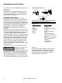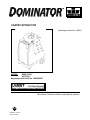
1
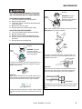
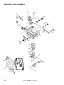
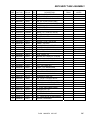
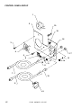
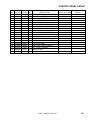
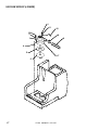
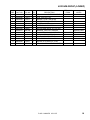
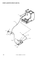
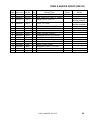
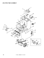
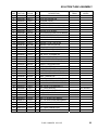
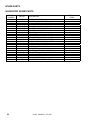
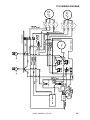
CARPET EXTRACTOR
Operating Instructions (ENG)
D250 (115V)
10070100
Beginning with Serial No. 1000054537
MODEL:
Read these instructions before operating the machine
AB
86038570 05/11/07
PRV NO. 98828
TABLE OF CONTENTS
MODEL ____________________________________________
DATE OF PURCHASE ________________________________
SERIAL NUMBER __________________________________
SALES REPRESENTATIVE # _________________________
DEALER NAME ____________________________________
Data Log/Table of Contents ....................1
Technical Specifications…………...……..11
Safety Instructions...................................2
Parts Lists................................................13-22
Grounding Instructions ............................3
Spare Parts..............................................23
Operations...............................................4
Wiring Diagram........................................24
Maintenance …………………………. .....6-9
Warranty ..................................................25
Troubleshooting ......................................10
INSPECTION
Carefully unpack and inspect your machine for shipping damage. Each unit is operated and thoroughly inspected
before shipping, and any damage is the responsibility of the carrier, who should be notified immediately.
1
D-250 86038570 05/11/07
SAFETY INSTRUCTIONS
IMPORTANT SAFETY INSTRUCTIONS
When using an electrical appliance, basic precaution
must always be followed, including the following:
READ ALL INSTRUCTIONS BEFORE USING THIS MACHINE.
This machine is for commercial use.
! WARNING:
To reduce the risk of fire, electric shock, or injury:
Connect to a properly grounded outlet. See Grounding Instructions.
Do not leave the machine unattended. Unplug machine from outlet when not in use and before
maintenance or service.
Use only indoors. Do not use outdoors or expose to rain.
Do not allow machine to be used as a toy. Close attention is necessary when used by or near
children.
Use only as described in this manual. Use only manufacturer’s recommended components and
attachments.
Do not use damaged electrical cord or plug. Follow all instructions in this manual concerning grounding
the machine. If the machine is not working properly, has been dropped, damaged, left outdoors, or
dropped into water, return it to an authorized service center.
Do not pull or carry machine by electrical cord, use as a handle, close a door on cord, or pull cord
around sharp edges or corners.
Do not run machine over cord. Keep cord away from heated surfaces.
Do not unplug machine by pulling on cord. To unplug, grasp the electrical plug, not the electrical cord.
Do not handle the electrical plug or machine with wet hands.
Do not operate the machine with any openings blocked. Keep openings free of debris that may reduce
airflow.
This machine is intended for cleaning carpet only.
Do not vacuum anything that is burning or smoking, such as cigarettes, matches, or hot ashes.
This machine is not suitable for picking up health endangering dust.
Turn off all controls before unplugging.
Machine can cause a fire when operating near flammable vapors or materials. Do not operate this
machine near flammable fluids, dust or vapors.
This machine is suitable for commercial use, for example in hotels, schools, hospitals,
factories, shops and offices for more than normal housekeeping purposes.
Maintenance and repairs must be done by qualified personnel.
If foam or liquid comes out of machine, switch off immediately.
SAVE THESE INSTRUCTIONS
D-250 86038570 05/11/07
2
GROUNDING INSTRUCTIONS
THIS PRODUCT IS FOR COMMERCIAL USE ONLY.
ELECTRICAL:
The amp, hertz, and voltage are listed on the data
label found on each machine. Using voltages above
or below those indicated on the data label will cause
serious damage to the motors.
GROUNDING INSTRUCTIONS:
This appliance must be grounded. If it should
malfunction or break down, grounding provides a path
of least resistance for electric current to reduce the
risk of electric shock. This appliance is equipped with
a cord having an equipment-grounding conductor and
grounding plug. The plug must be inserted into an
appropriate outlet that is properly installed and
grounded in accordance with all local codes and
ordinances.
The D250 is for use on a nominal 115-volt circuit, and
has a grounded plug that looks like the plug in “Fig. A”.
A temporary adaptor that looks like the adaptor in “Fig
. C” may be used to connect this plug to a 2-pole
receptacle as shown in “Fig. B”, if a properly grounded
outlet is not available. The temporary adaptor should
be used only until a properly grounded outlet (Fig. A)
can be installed by a qualified electrician. The green
colored rigid ear, lug, or the like extending from the
adaptor must be connected to a permanent ground
such as a properly grounded outlet box cover.
Whenever the adaptor is used, it must be held in place
by a metal screw.
The D250IE is for use on a nominal 230-volt circuit.
Improper connection of the
equipment-grounding
conductor can result in a risk
of electric shock. Check with a qualified electrician or
service person if you are in doubt as to whether the
outlet is properly grounded. Do not modify the plug
provided with the appliance - if it will not fit the outlet,
have a proper outlet installed by a qualified electrician.
3
PROPER GROUNDING (115V)
Grounding Pin
Grounded
Outlet
Metal Screw
Adaptor
Grounded Outlet Box
Fig. A
Fig. B
Tab For Grounding Screw
Adaptor
Fig. C
NOTE: In Canada, the use of a temporary adaptor is not
permitted by the Canadian Electrical Code
CHEMICALS
Suitable Chemicals
Alkalis
Detergents
Hydroxides
Soaps
Vinegar
Non-Compatible
Aldehydes
Aromatics Hydrocarbons
SP Butyls
Carbon Tetrachloride
Clorox*
Chlorinated Bleaches
Chlorinated Hydrocarbons
Lysol*
Methyl Ethel Ketone (MEK)
Perchorethylene (perc)
Phenolics
Trichlorethylene
D-Limonene
Warning:
Using the incompatible chemicals listed above will
damage the machine. Damages of this type are
not covered under the 6-3-1 warranty. Carefully
read ingredients on manufacturer's label before
using any product in this machine.
D-250 86038570 05/11/07
OPERATIONS
CARPET INSPECTION:
Determine precisely what areas you are going to
clean. Note problem areas in the carpet or tack
strip. Look for loose carpet, heavily damaged areas,
discolored stains, or grease spots that will require
prespotting. Note the carpet type. Check the
availability of hot water, drains, and suitable
electrical outlets. If the carpet is loose or worn, have
it repaired before attempting to clean it.
Plan the cleaning route, work from the most remote
area towards the exit. Try not to travel over the
cleaned areas when getting fresh water or dumping
old. Furniture should be moved out away from the
walls before cleaning. If furniture is moved back in
place before carpet is completely dry, place plastic
or foil protectors under the legs to prevent possible
carpet staining. When possible use a Windblower
(WB3) and open all windows and doors to speed
carpet drying.
ACCESSORIES:
The D-250 can be used with the following Windsor
equipment: Deluxe Hand Tool (86000020 – PRV
NO. DHT), Pile Jogger (86041760 - PRV NO. PJ2A),
Standard Floor Wands(SFW, 86000610 – PRV NO.
SW, 86288320 – PRV NO. SW-PRO, 86288310 –
PRV NO. PROW), & Wind Blower carpet
dryer(10040270 – PRV NO. WB3). Contact an
authorized Windsor dealer for assistance in
choosing the right equipment .
GENERAL INFORMATION:
On heavily soiled carpets, or on areas of high
foot traffic, it may be necessary to use a prespray
or traffic lane cleaner applied with a Pro-Spray. Do
not add presprays to the machine's solution tank. If
a spotter is used, follow the manufacturer's
instructions exactly as printed on the label. Remove
the spotter with the floor tool when done, spotter left
in the carpet may bleach or brown it permanently.
As the carpet is being cleaned, check to see if
there is foam building up in the recovery bucket.
Add a little defoaming compound to the recovery
tank but never to the solution tank.
For infrequent use or long periods of storage,
flush the system with a neutralizing solution of 1
quart white vinegar mixed with 2 gallons hot water.
Flush the system with clean hot water after
neutralizing.
PROTECT THIS MACHINE FROM FREEZING.
EQUIPMENT SET-UP:
1. Plug power cable from machine into properly
grounded wall outlet.
2. Turn vacuum motor switch on and off to make
sure there is electrical power at machine.
3. Connect vac hose to machine. Slide the swivel
cuff over the outlet on the tank.
4. Connect the hose set to the machine and wand.
Pull back the knurled collar on the quick
disconnect coupler and push onto the
connection on the chassis. To avoid leaks,
check to be sure a positive connection was
made.
5. Pour clean, hot water into the solution tank.
To avoid possible tank distortion, water
temperature must not exceed 140 F (60C).
6. Add a non-foaming cleaning solution
concentrate, for use in hot water extractors at
the proportions noted on the container (See list
below), into solution tank. NOTE: When using
powder cleaner, pre-mix with hot water in a
clean container before adding to the solution
tank.
7. Turn pump and vacuum switch(s) to the on
position. NOTE: Pump may have to be primed
for solution flow. (See Priming the Pump)
8. Start cleaning.
PRIMING THE PUMP
1. Connect priming hose to solution output on
machine.
2. Run open end of priming hose to vacuum intake.
3. Turn pump and both vacuums on and seal off
hose going into vacuum in take.
4. Do this for 30 seconds or until pump is putting
out a steady flow of water.
For hose fitting lubrication, use a light silicone
lubricant which will not damage o-rings.
D-250 86038570 05/11/07
4
OPERATION
HEATER OPERATION
The disconnect fittings on the
heater will become extremely
hot during operation. Allow sufficient time to
cool, or run solution through the machine with
the heater turned off before disconnecting the or
performing any maintenance on the heater.
Before disconnecting the heater, open wand valve to
relieve the system of all pressure by depressing the
valve trigger.
DO NOT spray water directly on to the heater. To
clean, unplug the unit and wipe with a damp cloth.
Make certain that the solution
tank is filled adequately before
plugging in the machine and heater.
1. Plug the machine and heater into separate
grounded circuits. The heater draws 15 amps of
current.
2. Turn the solution pump ON. Turn the heater
switch ON. The solution pump must be turned on
BEFORE the heater is turned on.
The heater requires about 5-6 minutes to reach
operating temperature, approximately 250°F.
When turning the machine and heater OFF, make
certain that you turn the heater off FIRST.
EMPTYING AND CLEANING
Always use defoamer if
foaming occurs. Foam will
suspend large particles that may damage
vacuum(s) as well as allow liquid into the vacuum
motor(s) without activating the float shutoff.
1. Before proceeding, make certain that the nozzle
is functioning properly.
a. To check, hold the wand about one foot
above the surface to be cleaned and open
the wand valve. A full spray should be
observed from the nozzle.
b. If the nozzle is not showing a full spray
pattern, adjust nozzle for proper pattern,
clean, or replace nozzle.
2. Normally, chemical is applied on the push stroke
while vacuuming is done on the pull stroke. For
heavily soiled carpets the hand tool may be used
in the scrubbing manner, applying chemical in
both the push and pull stroke. ALWAYS FINISH UP
AN AREA WITH A VACUUM PULL STROKE.
5
3. When cleaning, keep the working opening (wand
mouth) flat on the surface being cleaned. Keep
the wand moving when the valve is open.
4. The shutoff float inside the recovery tank will
impede the vacuum flow when the tank is full.
When this occurs, empty the recovery tank. Do
this by opening the dump valve located at the
back of the machine. NOTE: Dispose of waste in
a proper manner which would not violate any
Local, State or Federal law.
5. Once the recovery tank has been emptied, you
may once again proceed with cleaning.
Operating Vacuum after shutoff
has activated could draw water directly into the
vac motor. This will cause damage to the motor,
therefore voiding your warranty.
Always test carpet for color
fastness in an inconspicuous
place. Also, to avoid prolonged drying times, do
not spray too much solution in any one area.
SHUT DOWN AND STORAGE
1. Turn Switch OFF. Empty recovery tank
completely and rinse several times to remove any
dirt or debris that may be left behind.
2. Drain any unused cleaning solution from solution
tank and rinse with clean water to remove any
suds left behind by the cleaning chemicals.
NOTE: Dispose of waste in a proper manner
which would not violate any Local, State or
Federal law
3. Run a small amount of clean water through pump
if chemicals were used. This will help insure the
life of your pump.
4. Check the spray jet on the cleaning tool for full
spray pattern and inspect vac head for any
obstructions.
5. Remove as much moisture from system before
storing in cold climates. Excess water may freeze
during storage and crack internal components,
causing damage to the unit.
Before making any
adjustments or performing any
maintenance to your machine, disconnect the
power cord from the electrical source.
D-250 86038570 05/11/07
MAINTENANCE
2. Check hoses for wear, blockages, or damage.
Frayed or cracked hoses should be repaired or
replaced to eliminate vacuum or solution
pressure loss.
DAILY MAINTENANCE:
(At the end of each working day):
1. Flush the entire system, including floor tool,
hand tool, etc., with 1 to 3 gallons of clean, hot
water.
2. Vacuum out the solution tank .
3. Rinse tank with fresh water. Periodically inspect
the recovery tank and decontaminate if
necessary, using a Hospital Grade Virucide or a
1-10 bleach to water solution. Waste water
should be disposed of properly.
4. Remove lint build-up from the float shut-off
screen in the recovery tank . (Occasionally
check filter screen at the bottom of the solution
tank and rinse clean with hot water if
necessary).
3. Check all handles, switches, knobs, electrical
cables and connections on your machine for
damage. If the cable insulation is broken or
frayed, repair or replace it immediately. Don’t
take chances with electrical fire or shock.
4. Clean out solution tank and remove and clean
solution screen.
5. Clean outside of all tanks and check for
damage.
MONTHLY MAINTENANCE
1. Check all bearings for noise and wear.
2. Check all gaskets for wear and leakage.
5. Inspect hoses for wear. Frayed or cracked
hoses should be replaced to avoid vacuum or
solution pressure loss.
6. Inspect power cord for wear or damage. This
cable will lay on wet carpet. To prevent
electrical shock replace cords that are frayed or
have cracked insulation immediately.
3. Check pump pressure; observe spray pattern
and check with gauge if necessary.
4. Check overall performance of machine.
5. Grease piston inside pressure regulator.
SEMI-ANNUALLY
7. Ensure automatic shut-off ball is working
properly.
8. Clean all dirt and obstructions from drain valve
and gaskets to prevent possible leakage and
premature wear.
1. Check vacuum motor brushes.
LUBRICATION
For hose fitting lubrication, use a light silicone
lubricant which will not damage o-rings.
9. Run clean water through solution pump when
work is complete.
STORAGE
10. Empty both tanks and rinse, run vacuum (s) for
at least one minute to dry motor(s).
Thoroughly clean machine if it is to be stored.
Protect this machine from freezing while in storage.
11. Store with access covers removed to allow tanks
to dry.
HEATER MODEL STORAGE
Be sure to thoroughly drain water out of heater lines
prior to storage in colder climates. This heater will
freeze and possibly crack, voiding your warranty.
PERIODIC MAINTENANCE
1. Twice a month, flush a white vinegar solution
(One quart vinegar to two gallons of water) or
anti-browning solution (mixed as directed)
through the extractor, turning pump switch on/off
several times, flush with clean water. This will
prevent build-up of alkaline residue in the
system.
D-250 86038570 05/11/07
6
MAINTENANCE
SERVICE SCHEDULE
MAINTENANCE
Check machine for cord damage
Check recovery dome and gasket for
damage and cleanliness
Check hoses for wear, blockages, or
damage
Check handles, switches, and knobs
for damage
Check vac motor intake filter and clean
Run one gallon of water through
system
Clean out recovery tank and check
float valve to make sure it moves freely
Clean out solution tank and remove
and clean vacuum intake screen
Clean outside of all tanks and check for
damage
Run vac motor for at least one minute
to allow motor to dry
Store with dome off tank to allow the
tank to dry
Check all gaskets for wear and leakage
Check vacuum intake screen for
damage; replace if necessary
Check pump pressure; observe spray
pattern and check with gauge if
necessary
Check and clean solution screen
Check cables for fraying
Check overall performance of machine
Check vac motor carbon brushes
7
DAILY
*
WEEKLY
QUARTERLY
*
*
*
*
*
*
*
*
*
*
D-250 86038570 05/11/07
*
*
*
*
*
*
*
MAINTENANCE
Vacuum Motor Carbon Brushes Replacement (Ametek)
End Cap
ONLY QUALIFIED MAINTENANCE PERSONNEL
ARE TO PERFORM THE FOLLOWING REPAIRS.
VACUUM MOTOR REPLACEMENT
1. Turn off all switches and unplug machine.
2. Remove recovery tank.
3. Locate the vacuum motor wires and disconnect
at the connector.
4. Remove the vacuum motor.
5. Reverse process to install vacuum motor.
SOLUTION PUMP REPLACEMENT
1. Turn off all switches and unplug the machine.
2. Remove recovery tank.
3. Remove solution hoses from fittings in pump.
4. Remove the (2) screws that fasten the pump to
the frame.
5. Reverse process to install pump.
Carbon
Brushes
Note: When replacing carbon brushes loosen wire terminal
BEFORE removing screws on bracket.
Wire
Terminal
Note:
Place
stop in
groove.
Vacuum Motor Carbon Brushes Replacement (Windsor)
End Cap
Carbon
Brushes
WARNING: The green
ground wire must be
attached for safe operation.
See wiring diagram.
WARNING: The green
ground wire must be
attached for safe operation.
See wiring diagram.
If armature commutator is grooved, extremely pitted or not
concentric, the motor will need to be replaced or sent to a
qualified service center.
Wire Terminal
If armature commutator is grooved, extremely pitted or not
concentric, the motor will need to be replaced or sent to a
qualified service center.
Important:
These brushes wear quicker as the length shortens due to
increased heat. Spring inside brush housing will damage
motor if brushes are allowed to wear away completely.
Important:
These brushes wear quicker as the length shortens due to
increased heat. Spring inside brush housing will damage
motor if brushes are allowed to wear away completely.
3/8 (9.5mm)
Periodically check the length of the carbon brushes. Replace
both carbon brushes when either is less than 3/8" (9.5mm)
long.
3 [9.5mm]
8
Periodically check the length of the carbon brushes. Replace
both carbon brushes when either is less than 3/8" (9.5mm)
long.
D-250 86038570 05/11/07
8
MAINTENANCE
D-250 PUMP MAINTENANCE
Per manufacturer’s recommendations the following maintenance should be performed utilizing noted kits:
1.)
500 hours-Kit 86201080 – PRV NO. 250-75A replaces the V-packing, wave washer, packing spreader and
plunger guide.
2.)
500 hours-Kit 86201100 – PRV NO. 250-75C replaces the CAM bearing and insert.
3.)
1000 hours-kit 86201090 – PRV NO. 250-75B valve assembly and o-rings.
NOTE: Maintenance and repairs must be done by qualified personnel. Using non-Windsor parts to repair this
machine will void the warranty. Contact an authorized Windsor dealer for complete details.
9
D-250 86038570 05/11/07
TROUBLESHOOTING
TROUBLE SHOOTING CHART
PROBLEM
POSSIBLE CAUSE
No power to machine
Dead electrical circuit
Electrical shock
Electrical shock
Faulty power cord
Equipment not grounding
Receptacle not grounded
Vac motor speed varies or
doesn't run
Worn motor brushes
Motor worn out
Faulty switch
Loose vacuum dome
Crack in dome or poor joint
Loss of Vacuum
Solution hose fitting hard to
connect
Lint or dirt clogging vacuum
screen
Loose cuffs on vacuum hose
Vac motor seals leaking
Floor tool vac chamber
clogged
Vac motor, hose, or dome
gasket
Corrosion on fittings
Carpet not getting clean
Severe soil conditions
Carpet too wet
Over saturation
Carpet browning
Leaving carpet too wet
Too much chemical
Solution not flowing properly
Solution hose connection
Faulty pump
Faulty floor tool valve
Faulty pump switch
SOLUTION
Check building circuit breaker or fuse
box.
Replace.
Follow grounding instructions exactly.
Contact an electrician to check
building's wiring.
Replace.
Replace.
Replace.
Center and seal dome over tank.
Replace or repair using acrylic plastic
cement only.
With power off clean screen.
Tighten cuffs turning counterclockwise.
Replace.
Wash out with hose. Pick lint out with a
wire.
Replace.
Clean with steel wool.
Soak in acetic acid (white vinegar).
Lubricate lightly with silicone based
lubricant.
Make several passes at right angles to
each other.
Use a prespray.
Adjust solution pressure to lower
setting.
Make several passes without spray.
Check for loss of vac pressure.
Check label for correct solution
concentration.
Check for positive connection.
Repair or replace.
Repair or replace.
Repair.
D-250 86038570 05/11/07
10
TECHNICAL SPECIFICATIONS
TECHNICAL SPECIFICATIONS
ELECTRICAL:
ELECTRIC VACUUM MOTOR
SOLUTION PUMP
SOLUTION CAPACITY
RECOVERY CAPACITY
WEIGHT
LENGTH
WIDTH
POWER CABLE
11
115 V, 60 Hz, 15 Amps per power cable ((D250)
230 V, 50 Hz, 15 Amps (D250IE)
(1) –2/1.25 HP, 2 stage, Waterlift –150” (381cm)
250 psi, adj.
17 gallons (64.3ltr)
15 gallons (56.75ltr)
97 lbs. ( 44 kg)
20” (50.80 cm)
16” (40.64 cm)
2-25’ (6.35 m) (D250)
1-25' (6.35 m) (D250IE)
D-250 86038570 05/11/07
NOTES:
D-250 86038570 05/11/07
12
RECOVERY TANK ASSEMBLY
1
2
6
3
5
29
37
35
4
28
34
13
7
27
26
13
8
25
9
35
10
11
12
14
33
15
16
13
17
36
24
18
19
30
22
21
20
31
32
13
D-250 86038570 05/11/07
23
RECOVERY TANK ASSEMBLY
REF
1
2
3
4
5
6
7
8
9
10
11
12
13
14
15
16
17
18
19
20
21
22
23
24
25
26
27
28
29
30
31
32
33
34
35
SERIAL NO.
PART NO. PRV NO. QTY
DESCRIPTION
NOTES:
FROM
86033260
05151
1 TUBE ASM, RECOVERY TANK
86242230
500009
1 LABEL, WARNING
86002620 260-64A
1 ACCESS COVER CLEAR 6” W/RIM
86275800
70546
6 SCR, 8 X 3/4 PFHT/S BLK ZINC
86199840 090-12A
1 FLOAT CAGE ASSY COMPLETE SLIP
86033330
78475
1 VAC STACK ASM, 17 GAL PORTABLES
86202160
320-05
2 VELCRO STRAPS
86161460 15-808123
1 DUMP VALVE 2”
86161470 11-800444
1 ELBOW, 1.5 2” 45D PVC SCH40
86201510
390-26
3 SPACER NYLON 1/4 ID X 1/2 OD
86237440
35168
1 GASKET VAC MTR
86090970
360-24
1 PLATE, VAC
86010630
87013
7 WASHER, 1/4 ID X 5/8 OD SS
86003760
35166
1 GASKET, VAC MTR
86201970
065-92
3 VAC SPACER 2 1/4 II STAGE
86031620
85047
1 VAC MTR ASM, D/B RCVRY 115V 2ST
86202070 360-04B
- BRUSHES, VAC FOR 116392-00
SERVICE ONLY
1000121568
86135320
140687
- BRUSH SET, 120V VAC WINDSOR
SERVICE ONLY
86256490
70814
3 STUD, 1/4-20 X 4.5
86010640
87016
3 WASHER, #10 LOCK EXT STAR SS
86274980
70335
1 SCR, 10-32 X 1/2 PHTR GRN/GRND
86002390
20063
1 CLAMP, 1.75” WORM GEAR X .312
86004190
39337
1 HOSE, 1.5 BLK VAC X 24”
86234900
27508
1 CUFF, VAC HOSE BLU
86002380
20046
1 CLAMP, 2.25” WORM GEAR
86267480
880292
1 WIRE, 4” GRN/14 76010 X 76014
86033420
75334
1 TANK, RECOVERY DB DK GRY
86273780
70015
2 SCR, 1/4-20 3/4 HHCS SS DL
86091150
065-25
1 TANK BRACE ASM, D/B
86273830
70020
2 SCR, 1/4-20 X 1/2 HHCS SS NP
86200290
260-33
1 HOSEBARB, 1.5 MPT X 1.5
86200320
39574
1 HOSE ASM, 1/4 HP SLTN 16.5FT
86200320 150-44A
1 VAC HOSE 16-1/2’ W/CUFFS 1 1/2
86241910
47356
1 KIT, HOSE ASM W/BAG DOM50
86001750
14182
1 HOSE BAG 24” X 36”
86004000
35255
1 GASKET, TANK LID
86237770
35256
2 GASKET, DUMP VALVE
36
86005710
57105
3
NUT, 1/4-20 HEX W/ STAR WASHER
37
86090320
87257
1
WASHER, HOSEBARB
D-250 86038570 05/11/07
14
CONTROL PANEL GROUP
1
2
19
18
16
3
4
17
5
15
6
13
12
11
7
10
8
9
15
D-250 86038570 05/11/07
14
CONTROL PANEL GROUP
REF PART NO.
1 86199650
2 86090870
3 86276290
4 86199660
5 86273810
6 86256960
7 86199540
8 86199530
9 86202160
10 86256180
11 86201860
12 86201840
13 86201330
14 86261300
15 86233480
16 86200600
17 86005670
18 86200500
19 86005710
PRV NO. QTY
DESCRIPTION
SERIAL NO. FROM
070-08
1 FAN 105 CFM AXIAL
61367
1 PANEL ASM, CONT. 3 SW W/HEAT
70621006 4 SCR, #10 X 3/4 PPHST HI-LO BLK
070-08A 1 FAN FINGER GUARD
70018
1 SCR, 1/4-20 X 1 HHCS SS
72142
3 SWITCH, SPST 15A EURO ROCKER
060-04A 1 CORD 25’ BLK 14/3 SJTW/A PLUG
060-04
1 CORD 25’ BLK 12/3 SJTW/A PLUG
320-05
2 VELCRO STRAP
73195
2 STRAIN RELIEF, 1/2 NPT (.48ID)
330-06
1 TOGGLE SWITCH BOOT
330-05
1 TOGGLE SWITCH
335-04
1 TOGGLE SWITCH PLATE ON/OFF
51116
1 LIGHT ASM, 115V BRUSH WEAR
22046
1 CLIP, NEON LAMP
500345
1 LABEL DOM 3 SWITCH W/HEAT
57040
2 NUT, 1/2 NPT CONDUIT
140-11
57105
NOTES:
2 KNOB RT/TANK
3 NUT, 1/4-20 HEX W/STAR WASHER
D-250 86038570 05/11/07
16
VACUUM GROUP (LOWER)
1
11
10
12
2
9
3
8
4
5
7
6
17
D-250 86038570 05/11/07
VACUUM GROUP (LOWER)
REF
1
2
3
4
5
6
7
8
9
10
11
12
PART NO.
86274980
86256480
86010630
86201970
86003760
86090980
86031600
86202070
86135320
86282120
86002380
86267480
86010640
86005710
PRV NO.
70335
70813
87013
065-92
35166
360-24A
85045
360-04B
140687
39582
20046
880292
87016
57105
QTY
1
3
3
3
1
1
1
1
1
1
1
3
DESCRIPTION
SCR, 10-32 X 1/2 PHTR GRN/GRND
STUD, 14/20 X 3.5 SS
WASHER, 1/4 ID X 5/8 OD SS
VAC SPACER 2 1/4 II STAGE
GASKET, VAC MTR
PLATE ASM, VAC 90 DEG
VAC MTR ASM, D/B SLTN 115V 2ST
BRUSHES, VAC FOR 116392-00
BRUSH SET, 120V VAC WINDSOR
HOSE, VAC EXHAUST X 9”
CLAMP, 2.25” WORM GEAR
WIRE, 4” GRN/14 76010 X 76014
WASHER, #10 LOCK EXT STAR
NUT, 1/4-20 HEX W/ STAR WASHER
D-250 86038570 05/11/07
SERIAL NO.
FROM
NOTES:
SERVICE ONLY
1000121568 SERVICE ONLY
18
PUMP & HEATER GROUP (200 PSI)
1
2
3
4
9
6
5
8
7
15
10
12
11
13
14
19
D-250 86038570 05/11/07
16
PUMP & HEATER GROUP (200 PSI)
REF
1
2
PART NO.
86199640
86200260
PRV NO.
030-16
151-50C
QTY
DESCRIPTION
1 ELBOW, 1/4 NPT STREET LONG 90D
1 HOSE, PULSE 47.0 1/4MPT X 1/4 MPT
3
86197370
31017
1
ELBOW, 1/4 FPT X 1/4 FPT
4
86005590
56014
1
NIPPLE, 1/4 CLOSE
5
6
7
8
9
10
11
12
13
14
15
16
86033580
86197390
86201130
86233150
86197940
86005710
86006850
86200270
86197360
86197630
86090920
86280910
41515
31021
250-79
20042
40027
57105
70393
151-51C
31016
40042
065-28A
39174
1
1
1
2
1
2
2
1
1
1
1
1
HEATER ASM, D/B COMPLETE
ELBOW, 1/4 NPT 45 D STREET
PUMPTEC 200 PSI PUMP & MOTOR
CLAMP, 3/8 HOSE (D-SLOT)
HOSEBARB, 3/8 MPT X 1/2 90D DL
NUT, 1/4-20 HEX W/ STAR WASHER
SET SCR, 1/4-20 X 1.25L
HOSE, PULSE 14.0 1/4 MPT X 1/4 MPT
ELBOW 1/4 NPT STREET
HOSEBARB 1/4 MPT X 1/2 H 90D
PLATE, PUMP MOUNT
HOSE, 1/2 ID WIREBOUND X 23”
D-250 86038570 05/11/07
SERIAL NO.
FROM
NOTES:
INCLUDED IN
HEATER ASSEMBLY
INCLUDED IN
HEATER ASSEMBLY
20
SOLUTION TANK ASSEMBLY
1
2
3
4
29
5
6
28
30
27
7
1
8
15
26
10
11
25
12
13
14
19
24
11
11
12
23
38
39
16
17
18
34
16
9
35
36
33
36
21
22
32
12
37
21
12
11
40
40
D-250 86038570 05/11/07
20
20
SOLUTION TANK ASSEMBLY
REF
1
2
3
4
5
6
7
8
9
10
11
12
13
14
15
16
17
PART NO.
86201290
86201500
86002450
86005590
86199580
86200250
86091260
86201590
86090710
86198460
86273830
86010630
86090760
86006590
86240430
86274290
86006620
PRV NO.
280-02
260-71
22015
56014
250-35
151-50B
87217
290-08
010-02
20008
70020
87013
065-38B
70088
40083
70162
70127
QTY
2
1
1
1
1
1
1
1
1
1
18
10
1
1
1
3
4
DESCRIPTION
RIVET AL. 3/16 X 1/2 CLOSED
SOLUTION COVER D/B
COUPLER, 1/4 OD
NIPPLE, 1/4 CLOSE
D/B BPR 200 PSI
HOSE, 42” GRY 3/8 1/4MPT X CUT
WASHER, 9/16 ID BENT
SOL SCREEN (ACORN) W/ RUB BASE
AXLE ASM, RIGHT
CLAMP, 5/8 NYLON UL/CSA
SCR, 1/4-20 X 1/2 HHCS SS
WASHER, 1/4 ID X 5/8 OD SS
BRACKET HEATER D/B 200
SCR, #10-32 X 1/2 PPHMS SS
HOSEBARB, 3/8MT X 3/8 NYLON
SCR, 10-32 X 3/8 PPHMS SS
SCR, 6-32 X 1/4 PPHMS SS
18
19
20
21
22
23
24
25
26
27
28
29
30
31
32
33
34
35
36
37
86271350
86200020
86271380
86202250
86090700
86090840
86199430
86033530
86200680
86202240
86242130
86232790
86276270
86270900
86202280
86091430
86079100
86070910
86005710
86273780
57187
41393
57196
040-06
010-01
065-28
040-03
75349
500378
390-24
48100
27912
70619
57037
89252
05253
620065
140758
57105
70015
4
1
2
2
1
1
2
1
1
2
1
1
1
1
2
1
2
1
2
4
NUT, 6-32 ACORN, ZINC
HINGE, ACCESS PANEL
NUT, 1/2 PUSH-ON DOME CAP
WHEEL 8’ CENTERED HUB
AXLE ASM, LEFT
200 PUMP SUPPORT
CASTER SWIVEL 4” SWIVEL
TANK, SOLUTION DOM 250 DK BLU
LABEL, DOMINATOR
WASHER, 1/4 X 5/8 BONDED NEOPRN
KNOB, HEX PRESS-LOC WING
CHAIN ASM, #10 BEAD S/S W/EYES
SCR, 1/4-20 X 2.0 HHMS SS F/T
NUT, 1/4-20 WING SS
WHEEL, 12” BLK CNTRD HUB
AXLE ASSEMBLY D.B.
PLATE AXLE
BRKT 12” WHEEL MNT BRACE
NUT, 1/4 -20 HEX W/STAR WASHER
SCR, 1/4-20 X 3/4 HHCS SS NP
38
86006850
70393
1
SET SCR, 1/4 –20 X 1.25
39
86271370
57189
1
NUT, 1/4-20 FLANGE LOCK
40
86010710
87080
2
WASHER, .5 X 1.25 FLAT GR8 PLT
D-250 86038570 05/11/07
SERIAL NO.
FROM
NOTES:
NOT SHOWN
1000137325
1000137325
1000137325
1000137325
22
SPARE PARTS
SUGGESTED SPARE PARTS
PART
NUMBER
86199890
86199240
86201810
86201790
86201150
86201160
86201170
86202070
86135320
86031620
86031600
86201130
86256960
86202280
86271380
86199430
86200500
86002620
86201590
86199620
86261300
86201840
86200300
23
PRV NO.
DESCRIPTION
100-04A
250-33A
130-14I
130-14C
250-79E
250-79F
250-79G
360-04B
140687
85047
85045
250-79
72142
89252
57196
040-03
140-11
260-64A
290-08
370-08
51116
330-05
39572
FUSE 3 AMP 200 PSI
BPR REPAIR KIT PUMPTEC
THERMOSTAT W/SPADE LEADS
THERMOSTAT RESET
PUMPTEC 300/400PSI PUMP KIT 1
PUMPTEC 300PSI PUMP KIT 2
PUMPTEC 300PSI REBUILD KIT 3
BRUSHES, VAC FOR 116392-00
BRUSH SET, 120V VAC WINDSOR
VAC MOTOR ASM, RCVRY 115V 2ST
VAC MOTOR ASM, SLTN 115V 2ST
PUMPTEC 200PSI PUMP & MOTOR
SWITCH, SPST 15A EURO ROCKER
WHEEL 12” BLK CENTERED HUB
NUT, 1/2 PUSH-ON DOME CAP
CASTER SWIVEL 4” SWIVEL
KNOB RT/TANK
ACCESS COVER CLEAR 6” W/RIM
SOL SCREEN (ACORN) W/RUB BASE
DUMP VALVE SEAL 1-1/2”
LIGHT ASM, 115V BRUSH
TOGGLE SWITCH
HOSE, PRIMING KIT FEMALE QC
D-250 86038570 05/11/07
SERIAL NO.
FROM
1000121568
115V WIRING DIAGRAM
D-250 86038570 05/11/07
24