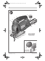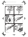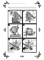
1
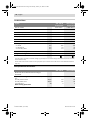
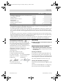
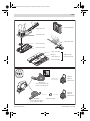
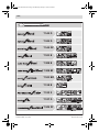
OBJ_DOKU-10875-001.fm Page 1 Monday, January 21, 2008 4:20 PM
Robert Bosch GmbH
Power Tools Division
70745 Leinfelden-Echterdingen
www.bosch-pt.com
GST Professional
1 609 929 N50 (2008.01) T / 147
135 CE | 135 BCE
de
en
fr
es
pt
it
nl
Originalbetriebsanleitung
Original instructions
Notice originale
Manual original
Manual original
Istruzioni originali
Oorspronkelijke gebruiksaanwijzing
da
sv
no
fi
el
tr
Original brugsanvisning
Bruksanvisning i original
Original driftsinstruks
Alkuperäiset ohjeet
Πρωτότυπο οδηγιών χρήσης
Orijinal işletme talimat
OBJ_BUCH-635-001.book Page 2 Monday, January 21, 2008 4:22 PM
2|
Deutsch . . . . . . . . . . . . . . . . . . . . . . . . . . . . Seite
6
English . . . . . . . . . . . . . . . . . . . . . . . . . . . . . Page
17
Français . . . . . . . . . . . . . . . . . . . . . . . . . . . . Page
28
Español. . . . . . . . . . . . . . . . . . . . . . . . . . . . Página
39
Português . . . . . . . . . . . . . . . . . . . . . . . . . . Página
50
Italiano . . . . . . . . . . . . . . . . . . . . . . . . . . . . Pagina
61
Nederlands . . . . . . . . . . . . . . . . . . . . . . . . . Pagina
72
Dansk . . . . . . . . . . . . . . . . . . . . . . . . . . . . . . Side
83
Svenska . . . . . . . . . . . . . . . . . . . . . . . . . . . . Sida
93
Norsk . . . . . . . . . . . . . . . . . . . . . . . . . . . . . . Side 103
Suomi . . . . . . . . . . . . . . . . . . . . . . . . . . . . . . . Sivu 113
Ελληνικά . . . . . . . . . . . . . . . . . . . . . . . . . . . Σελίδα 123
Türkçe . . . . . . . . . . . . . . . . . . . . . . . . . . . . . Sayfa 135
1 609 929 N50 | (21.1.08)
Bosch Power Tools
OBJ_BUCH-635-001.book Page 3 Monday, January 21, 2008 4:22 PM
3|
5
4
3
2
1
6
7
19
18
17
16
13
12
11
10
9
GST 135 BCE
Professional
8
14
15
1
4
3
GST 135 CE
Professional
1 609 929 N50 | (21.1.08)
Bosch Power Tools
OBJ_BUCH-635-001.book Page 4 Monday, January 21, 2008 4:22 PM
4|
B
A
17
14
19
13
15
15
D
C
20
7
7
E
20
F
9
8
21
9
6
7
1 609 929 N50 | (21.1.08)
Bosch Power Tools
OBJ_BUCH-635-001.book Page 5 Monday, January 21, 2008 4:22 PM
5|
H
G
22
9 23 24
9 23 24
I
J
K
L
28
25
1 609 929 N50 | (21.1.08)
26 27
25
26
Bosch Power Tools
OBJ_BUCH-635-001.book Page 17 Monday, January 21, 2008 4:22 PM
English | 17
General Power Tool Safety
Warnings
en
WARNING Read all safety warnings and all
instructions. Failure to follow
the warnings and instructions may result in electric shock, fire and/or serious injury.
Save all warnings and instructions for future
reference.
The term “power tool” in the warnings refers
to your mains-operated (corded) power tool
or battery-operated (cordless) power tool.
1) Work area safety
a) Keep work area clean and well lit. Cluttered or dark areas invite accidents.
b) Do not operate power tools in explosive
atmospheres, such as in the presence of
flammable liquids, gases or dust. Power
tools create sparks which may ignite the
dust or fumes.
c) Keep children and bystanders away
while operating a power tool. Distractions can cause you to lose control.
2) Electrical safety
a) Power tool plugs must match the outlet.
Never modify the plug in any way. Do not
use any adapter plugs with earthed
(grounded) power tools. Unmodified
plugs and matching outlets will reduce
risk of electric shock.
b) Avoid body contact with earthed or
grounded surfaces, such as pipes, radiators, ranges and refrigerators. There is
an increased risk of electric shock if your
body is earthed or grounded.
c) Do not expose power tools to rain or wet
conditions. Water entering a power tool
will increase the risk of electric shock.
d) Do not abuse the cord. Never use the
cord for carrying, pulling or unplugging
the power tool. Keep cord away from
heat, oil, sharp edges and moving parts.
Damaged or entangled cords increase the
risk of electric shock.
Bosch Power Tools
e) When operating a power tool outdoors,
use an extension cord suitable for outdoor use. Use of a cord suitable for outdoor use reduces the risk of electric
shock.
f) If operating a power tool in a damp location is unavoidable, use a residual current
device (RCD) protected supply. Use of an
RCD reduces the risk of electric shock.
3) Personal safety
a) Stay alert, watch what you are doing and
use common sense when operating a
power tool. Do not use a power tool while
you are tired or under the influence of
drugs, alcohol or medication. A moment
of inattention while operating power tools
may result in serious personal injury.
b) Use personal protective equipment. Always wear eye protection. Protective
equipment such as dust mask, non-skid
safety shoes, hard hat, or hearing protection used for appropriate conditions will
reduce personal injuries.
c) Prevent unintentional starting. Ensure
the switch is in the off-position before
connecting to power source and/or battery pack, picking up or carrying the tool.
Carrying power tools with your finger on
the switch or energising power tools that
have the switch on invites accidents.
d) Remove any adjusting key or wrench before turning the power tool on. A wrench
or a key left attached to a rotating part of
the power tool may result in personal injury.
e) Do not overreach. Keep proper footing
and balance at all times. This enables
better control of the power tool in unexpected situations.
f) Dress properly. Do not wear loose clothing or jewellery. Keep your hair, clothing
and gloves away from moving parts.
Loose clothes, jewellery or long hair can
be caught in moving parts.
1 609 929 N50 | (21.1.08)
OBJ_BUCH-635-001.book Page 18 Monday, January 21, 2008 4:22 PM
18 | English
g) If devices are provided for the connection of dust extraction and collection facilities, ensure these are connected and
properly used. Use of dust collection can
reduce dust-related hazards.
5) Service
a) Have your power tool serviced by a qualified repair person using only identical
replacement parts. This will ensure that
the safety of the power tool is maintained.
4) Power tool use and care
a) Do not force the power tool. Use the correct power tool for your application. The
correct power tool will do the job better
and safer at the rate for which it was designed.
b) Do not use the power tool if the switch
does not turn it on and off. Any power tool
that cannot be controlled with the switch
is dangerous and must be repaired.
c) Disconnect the plug from the power
source and/or the battery pack from the
power tool before making any adjustments, changing accessories, or storing
power tools. Such preventive safety
measures reduce the risk of starting the
power tool accidentally.
d) Store idle power tools out of the reach of
children and do not allow persons unfamiliar with the power tool or these instructions to operate the power tool.
Power tools are dangerous in the hands of
untrained users.
e) Maintain power tools. Check for misalignment or binding of moving parts,
breakage of parts and any other condition that may affect the power tool’s operation. If damaged, have the power tool
repaired before use. Many accidents are
caused by poorly maintained power tools.
f) Keep cutting tools sharp and clean. Properly maintained cutting tools with sharp
cutting edges are less likely to bind and
are easier to control.
g) Use the power tool, accessories and tool
bits etc. in accordance with these instructions, taking into account the working conditions and the work to be performed. Use of the power tool for
operations different from those intended
could result in a hazardous situation.
1 609 929 N50 | (21.1.08)
Machine-specific
Safety Warnings
f Keep hands away from the sawing range.
Do not reach under the workpiece. Contact
with the saw blade can lead to injuries.
f Apply the machine to the workpiece only
when switched on. Otherwise there is danger of kickback when the cutting tool jams in
the workpiece.
f Pay attention that the base plate 9 rests
securely on the material while sawing. A
jammed saw blade can break or lead to kickback.
f When the cut is completed, switch off the
machine and then pull the saw blade out of
the cut only after it has come to a standstill.
In this manner you can avoid kickback and
can place down the machine securely.
f Use only sharp, flawless saw blades. Bent or
unsharp saw blades can break or cause kickback.
f Do not brake the saw blade to a stop by applying side pressure after switching off. The
saw blade can be damaged, break or cause
kickback.
f Use suitable detectors to determine if utility lines are hidden in the work area or call
the local utility company for assistance.
Contact with electric lines can lead to fire
and electric shock. Damaging a gas line can
lead to explosion. Penetrating a water line
causes property damage or may cause an
electric shock.
f Hold the power tool only by the insulated
gripping surfaces when performing an operation where the cutting tool may contact
hidden wiring or its own cord. Contact with
Bosch Power Tools
OBJ_BUCH-635-001.book Page 19 Monday, January 21, 2008 4:22 PM
English | 19
a “live” wire will also make exposed metal
parts of the power tool “live” and shock the
operator.
f Secure the workpiece. A workpiece clamped
with clamping devices or in a vice is held
more secure than by hand.
Product Features
The numbering of the product features refers to
the illustration of the machine on the graphics
page.
1 Plastic cap
f Keep your workplace clean. Blends of materials are particularly dangerous. Dust from
light alloys can burn or explode.
2 Lock-on button for On/Off switch
(GST 135 BCE)
f Always wait until the machine has come to
a complete stop before placing it down. The
tool insert can jam and lead to loss of control
over the power tool.
4 Handle
f Never use the machine with a damaged cable. Do not touch the damaged cable and
pull the mains plug when the cable is damaged while working. Damaged cables increase the risk of an electric shock.
8 Sliding shoe*
3 On/Off switch
5 Thumbwheel for stroke rate preselection
6 Extraction adapter*
7 Vacuum connection*
9 Base plate
10 Switch for sawdust blowing device
11 Adjusting lever for orbital action
12 Precision-Control button
13 Precision-Control guide cheeks
Functional Description
Read all safety warnings and all instructions. Failure to follow the
warnings and instructions may result in electric shock, fire and/or serious injury.
While reading the operating instructions, unfold
the graphics page for the machine and leave it
open.
Intended Use
The machine is intended for making separating
cuts and cut-outs in wood, plastic, metal, ceramic plates and rubber while resting firmly on
the workpiece. It is suitable for straight and
curved cuts with mitre angles to 45°. The saw
blade recommendations are to be observed.
Bosch Power Tools
14 Guide roller
15 Saw blade*
16 Contact protector
17 Stroke rod
18 Dust cover for vacuuming*
19 SDS clamping lever for saw blade release
20 Vacuum hose*
21 Splinter guard*
22 Scale for mitre angle
23 Thumbwheel for pre-tension of base plate
24 Base plate clamping lever
25 Lead for the parallel guide
26 Locking screw for parallel guide*
27 Parallel guide with circle cutter*
28 Centring tip of the parallel guide*
*The accessories illustrated or described are not included as standard delivery.
1 609 929 N50 | (21.1.08)
OBJ_BUCH-635-001.book Page 20 Monday, January 21, 2008 4:22 PM
20 | English
Technical Data
Jigsaw
GST 135 CE
Professional
GST 135 BCE
Professional
Article number
0 601 510 7..
0 601 511 7..
–
z
Stroke rate control
Stroke rate preselection
z
z
Rated power input
W
720
720
Output power
W
310
310
Stroke rate at no load n0
spm
500 – 2800
500 – 2800
Stroke
mm
26
26
Cutting capacity, max.
– in wood
– in aluminium
– in non-alloy steel
mm
mm
mm
135
20
10
135
20
10
Bevel cuts (left/right), max.
Weight according to EPTA-Procedure 01/2003
°
45
45
kg
2.6
2.7
/ II
/ II
Protection class
The values given are valid for nominal voltages [U] of 230/240 V. For lower voltage and models for specific countries,
these values can vary.
Please observe the article number on the type plate of your machine. The trade names of the individual machines
may vary.
Noise/Vibration Information
GST 135 CE
GST 135 BCE
84
95
3
84
95
3
Measured values determined according to
EN 60745.
Typically the A-weighted noise levels of the product
are:
Sound pressure level
Sound power level
Uncertainty K=
Wear hearing protection!
1 609 929 N50 | (21.1.08)
dB(A)
dB(A)
dB
Bosch Power Tools
OBJ_BUCH-635-001.book Page 21 Monday, January 21, 2008 4:22 PM
English | 21
Vibration total values (triax vector sum) determined
according to EN 60745:
Cutting wood:
Vibration emission value ah
Uncertainty K
Cutting sheet metal:
Vibration emission value ah
Uncertainty K
GST 135 CE
GST 135 BCE
m/s2
m/s2
6
2
5
1.5
m/s2
m/s2
6
1.5
3,5
1.5
The vibration emission level given in this information sheet has been measured in accordance with
a standardised test given in EN 60745 and may be used to compare one tool with another. It may
be used for a preliminary assessment of exposure.
The declared vibration emission level represents the main applications of the tool. However if the
tool is used for different applications, with different accessories or poorly maintained, the vibration emission may differ. This may significantly increase the exposure level over the total working
period.
An estimation of the level of exposure to vibration should also take into account the times when
the tool is switched off or when it is running but not actually doing the job. This may significantly
reduce the exposure level over the total working period.
Identify additional safety measures to protect the operator from the effects of vibration such as:
maintain the tool and the accessories, keep the hands warm, organisation of work patterns.
Declaration of Conformity
We declare under our sole responsibility that
the product described under “Technical Data” is
in conformity with the following standards or
standardization documents: EN 60745 according to the provisions of the directives
2004/108/EC, 98/37/EC (until Dec. 28, 2009),
2006/42/EC (from Dec. 29, 2009 on).
Technical file at:
Robert Bosch GmbH, PT/ESC,
D-70745 Leinfelden-Echterdingen
Dr. Egbert Schneider
Senior Vice President
Engineering
Dr. Eckerhard Strötgen
Head of Product
Certification
Assembly
f Before any work on the machine itself, pull
the mains plug.
Replacing/Inserting the Saw Blade
f When mounting the saw blade, wear protective gloves. Danger of injury when touching
the saw blade.
Selecting a Saw Blade
An overview of recommended saw blades can
be found at the end of these instructions. Use
only T-shank saw blades. The saw blade should
not be longer than required for the intended cut.
Use a thin saw blade for narrow curve cuts.
Inserting the Saw Blade (see figure A)
14.12.2007, Robert Bosch GmbH, Power Tools Division
D-70745 Leinfelden-Echterdingen
If required, remove the dust cover 18 (see “Dust
Cover”).
Insert the saw blade 15 (teeth in cutting direction) into the stroke rod until it latches 17.
Bosch Power Tools
1 609 929 N50 | (21.1.08)
OBJ_BUCH-635-001.book Page 22 Monday, January 21, 2008 4:22 PM
22 | English
While inserting the saw blade, pay attention that
the back of the saw blade is positioned in the
groove of the guide roller 14.
17
13
14
– Use dust extraction whenever possible.
– Provide for good ventilation of the working place.
– It is recommended to wear a P2 filterclass respirator.
Observe the relevant regulations in your
country for the materials to be worked.
Dust Cover
Mount the dust cover 18 before connecting the
machine to the dust extraction.
Note: If the grooves of the saw blade holder are
not in the position shown in the figure or when
the Precision-Control guide cheeks 13 are
closed, then the saw blade 15 cannot be inserted into the stroke rod 17. Briefly press the SDS
clamping lever 19 toward the side and release it
again.
f Check the tight seating of the saw blade. A
loose saw blade can fall out and lead to injuries.
Ejecting the Saw Blade (see figure B)
f When ejecting the saw blade, hold the machine in such a manner that no persons or
animals can be injured by the ejected saw
blade.
Press the SDS clamping lever 19 sideward to
the stop. The Precision-Control guide cheeks 13
are released and the saw blade 15 is ejected.
Dust/Chip Extraction
f Dusts from materials such as lead-containing
coatings, some wood types, minerals and
metal can be harmful to one’s health. Touching or breathing-in the dusts can cause allergic reactions and/or lead to respiratory infections of the user or bystanders.
Certain dusts, such as oak or beech dust, are
considered as carcinogenic, especially in
connection with wood-treatment additives
(chromate, wood preservative). Materials
containing asbestos may only be worked by
specialists.
1 609 929 N50 | (21.1.08)
Mount the dust cover 18 onto the machine in such
a manner that the holders in the centre of the
dust cover engage on the contact protector 16.
For work without dust extraction, the dust cover
18 can be removed. To remove the dust cover
18, grasp it by the side and pull it off toward the
front.
Connecting the Dust Extraction
(see figures C–E)
Mount the vacuum connection 7 into the opening of the base plate 9. Make sure that the plastic tip of the vacuum connection engages into
the corresponding opening on the housing as
shown in the figure.
Depending on the machine model, place a vacuum hose 20 (accessory) either directly onto the
vacuum connection 7 or cut off the old hose
end, screw the extraction adapter 6 (accessory)
onto the hose end and insert it directly into the
vacuum connection 7. Connect the vacuum hose
20 with a vacuum cleaner (accessory). An overview for the connection of various vacuum
cleaners can be found at the end of these instructions.
Switch the saw dust blower off when a dust extraction system is connected (see “Sawdust
Blower Device”).
To enable optimum dust extraction, use the
splinter guard 21 if possible.
The vacuum cleaner must be suitable for the material being worked.
When vacuuming dry dust that is especially detrimental to health or carcinogenic, use a special
vacuum cleaner.
Bosch Power Tools
OBJ_BUCH-635-001.book Page 23 Monday, January 21, 2008 4:22 PM
English | 23
Splinter Guard (see figure F)
The splinter guard 21 (accessory) can prevent
fraying of the surface while sawing wood. The
splinter guard can only be used for certain saw
blade types and only for cutting angles of 0°.
When sawing with the splinter guard, the base
plate 9 must not be moved back for cuts that are
close to the edge.
Press the splinter guard 21 from below into the
base plate 9 (with the notch facing upward as
shown in the figure).
The splinter guard 21 can be inserted into the
base plate in 2 positions. For narrow saw
blades, insert the splinter guard fully to the
front; for wider saw blades, insert it further to
the rear in the base plate 9.
When using the sliding shoe 8, the splinter
guard 21 is not inserted into the base plate 9,
but into the sliding shoe.
Sliding Shoe
When working surfaces that are easily
scratched, the sliding shoe 8 can be attached
onto the base plate 9 in order to prevent the surface from being scratched.
To attach the sliding shoe 8, insert it at the front
of the base plate 9, push the rear part upward
and allow it to latch.
Operating Modes
f Before any work on the machine itself, pull
the mains plug.
Orbital Action Settings
The four orbital action settings allow for optimal
adaptation of cutting speed, cutting capacity
and cutting pattern to the material being sawed.
The orbital action can be adjusted with the adjusting lever 11, even during operation.
Bosch Power Tools
– Select a lower orbital action setting (or
switch it off) for a finer and cleaner cutting
edge.
– For thin materials such as sheet metal,
switch the orbital action off.
– For hard materials such as steel, work with
low orbital action.
– For soft materials and when sawing in the direction of the grain, work with maximum orbital action.
Adjusting the Cutting Angle (see figure G)
The base plate 9 can be swivelled by 45° to the
left or right for mitre cuts.
Remove the dust cover 18 and the vacuum connection 7.
Release the clamping lever 24 of the base plate
and lightly push the base plate 9 toward the
mains cable.
For adjustment of precise mitre angles, the base
plate has adjustment notches on the left and
right at 0° and 45°. Swivel the base plate 9 to
the desired position according to the scale 22.
Other mitre angles can be adjusted using a protractor.
Afterwards, push the base plate 9 to the stop in
the direction of the saw blade 15.
Operation
Setting 0
Setting I
Setting II
Setting III
The optimal orbital action setting for the respective application can be determined through
practical testing. The following recommendations apply:
No orbital action
Small orbital action
Medium orbital action
Large orbital action
Close the base plate clamping lever 24 to lock
the base plate in the adjusted position.
The dust cover 18, vacuum connection 7 and
splinter guard 21 cannot be used for mitre cuts.
Offsetting the Base Plate (see figure H)
For sawing close to edges, the base plate 9 can
be offset to the rear.
Remove the dust cover 18 (see “Dust Cover”,
page 22).
Release the clamping lever 24 of the base plate
and push the base plate 9 toward the mains
cable to the stop.
Close the base plate clamping lever 24 to lock
the base plate in the adjusted position.
1 609 929 N50 | (21.1.08)
OBJ_BUCH-635-001.book Page 24 Monday, January 21, 2008 4:22 PM
24 | English
Sawing with the base plate 9 offset is possible
only with a mitre angle of 0°. In addition, the
parallel guide with circle cutter 27 (accessory)
as well as the splinter guard 21 may not be used.
Changing the Pre-tension of the Base Plate
With the thumbwheel 23, the pre-tension of the
base plate clamping lever 24 can be changed.
When the base plate 9 is not seated tightly after
closing the lever, open the clamping lever and
turn the thumbwheel for pre-tension of the base
plate in the “+” direction.
When the base plate cannot be adjusted or only
with difficulty after opening the clamping lever,
turn the thumbwheel in the “– ” direction.
Precision Control
Precision Control improves the lateral stability
of the inserted saw blade. The lateral guidance
from the Precision-Control guide cheeks 13 enable precise cuts.
To switch on Precision Control, push button 12.
To switch off Precision Control, press the SDS
lever 19 sideward to the stop and eject the saw
blade 15. Reinsert the saw blade afterwards, if
required.
f Wear protective gloves when changing the
saw blade. The ejected saw blade can be hot.
Precision Control can be used for all applications, even for mitre cuts. It is especially recommended for cuts in thick wood: The lateral guidance ensures that the cutting angle is
maintained and reduces run-off of the saw blade
(also see “Sawing Thick Wood”, page 25).
Sawdust Blower Device
With the air jet of the sawdust blower device 10,
the cutting line can be kept free of dust and
chips.
Switching on the sawdust blower device: For
cuts in materials with high removal rate, such as
in wood, plastic, etc., push the switch 10 to
position “I”.
Switching off the sawdust blower device: For
cuts in metal and when a dust extraction system
is connected, push the switch 10 to position “0”.
1 609 929 N50 | (21.1.08)
Starting Operation
f Observe correct mains voltage! The voltage
of the power source must agree with the
voltage specified on the nameplate of the
machine. Power tools marked with 230 V
can also be operated with 220 V.
Switching On and Off (GST 135 CE)
To start the machine, push the On/Off switch 3
forwards.
To switch off the machine, push the On/Off
switch 3 toward the rear so that the “0” is indicated on the switch.
Switching On and Off (GST 135 BCE)
To start the machine, press the On/Off switch 3.
To lock the On/Off switch 3, keep it depressed
and push the lock-on button 2 to the right or
left.
To switch off the machine, release the On/Off
switch 3. When the On/Off switch 3 is locked,
press it first and then release it.
Controling the Stroke Rate (GST 135 BCE)
Increasing or reducing the pressure on the
On/Off switch 3 enables stepless stroke-rate
control of the switched-on machine.
Light pressure on the On/Off switch 3 results in
a low stroke rate. Increasing the pressure also
increases the stroke rate.
When the On/Off switch 3 is locked, it is not
possible to reduce the stroke rate.
Presetting the Stroke Rate
With the thumbwheel for stroke rate preselection 5, the stroke rate can be preset and
changed during operation.
1 – 2:
3 – 4:
5 – 6:
Low stroke rate
Medium stroke rate
High stroke rate
The required stroke rate is dependent on the
material and the working conditions and can be
determined by a practical trial.
Reducing the stroke rate is recommended when
the saw blade engages in the material as well as
when sawing plastic and aluminium.
Bosch Power Tools
OBJ_BUCH-635-001.book Page 25 Monday, January 21, 2008 4:22 PM
English | 25
After longer periods of work at low stroke rate,
the machine can heat up considerably. Remove
the saw blade from the machine and allow the
machine to cool down by running it for approx.
3 minutes at maximum stroke rate.
Working Advice
f When working small or thin work pieces, always use a sturdy support or a saw table
(accessory).
While working, hold the machine by the handle
4 and guide it alongside the desired cutting line.
For precise cuts and quiet running, guide the
machine additionally with the other hand by the
plastic cap 1.
Contact Protector
The contact protector 16 attached to the casing
prevents accidental touching of the saw blade
during the working procedure and may not be
removed.
Sawing Thick Wood
For straight cuts in thick wood, please observe
the following recommendations:
– Switch on Precision Control for lateral guidance of the saw blade (see “Precision Control”, page 24).
– Use Bosch saw blades marked with “Precision for Wood”.
– Adjust the precise mitre angle using an angle
measurer.
– Saw applying only low feed. Orbital action
and stroke ensure sufficient working process.
– Always guide the machine resting firmly
against the parallel guide 27 or an auxiliary
guide rail. Avoid lateral pressure on the handle 4 to prevent tilting of the machine.
– While sawing, hold the machine with one
hand by the handle 4 and with the other hand
by the plastic cap 1.
Bosch Power Tools
Plunge Cutting (see figures I – J)
f Plunge cuts may only be applied to soft
materials, such as wood, gypsum plaster
boards, etc.!
Use only short saw blades for plunge cutting.
Plunge cutting is possible only with the mitre
angle set at 0°.
Place the machine with the front edge of the
base plate 9 on to the workpiece without the
saw blade 15 touching the workpiece and
switch on. For machines with stroke rate control, select the maximum stroke rate. Firmly
hold the machine against the workpiece and by
tilting the machine, slowly plunge the saw blade
into the workpiece.
When the base plate 9 fully lays on the workpiece,
continue sawing along the desired cutting line.
Parallel Guide with Circle Cutter (Accessory)
For cuts using the parallel guide with circle cutter 27 (accessory), the thickness of the material
must not exceed a maximum of 30 mm.
Parallel Cuts (see figure K): Loosen the locking
screw 26 and slide the scale of the parallel guide
through the lead 25 in the base plate. Set the
desired cutting width as the scale value on the
inside edge of the base plate. Tighten the locking screw 26.
Circular Cuts (see figure L): Set the locking
screw 26 to the other side of the parallel guide.
Slide the scale of the parallel guide through the
lead 25 in the base plate. Drill a hole in the workpiece centred in the section to be sawn. Insert
the centring tip 28 through the inside opening of
the parallel guide and into the drilled hole. Set
the radius as the scale value on the inside edge
of the base plate. Tighten the locking screw 26.
Coolant/Lubricant
When sawing metal, coolant/lubricant should be
applied alongside cutting line because of the
material heating up.
1 609 929 N50 | (21.1.08)
OBJ_BUCH-635-001.book Page 26 Monday, January 21, 2008 4:22 PM
26 | English
Maintenance and Service
Maintenance and Cleaning
f Before any work on the machine itself, pull
the mains plug.
f For safe and proper working, always keep
the machine and ventilation slots clean.
Clean the saw blade holder regularly. For this,
remove the saw blade from the machine and
lightly tap out the machine on a level surface.
Heavy contamination of the machine can lead to
malfunctions. Therefore, do not saw materials
that produce a lot of dust from below or overhead.
f In extreme working conditions, conductive
dust can accumulate in the interior of the
machine when working with metal. The protective insulation of the machine can be degraded. The use of a stationary extraction
system is recommended in such cases as
well as frequently blowing out the ventilation slots and installing a residual current
device (RCD).
Lubricate the guide roller 14 occasionally with a
drop of oil.
Check the guide roller 14 regularly. If worn, it
must be replaced through an authorised Bosch
after-sales service agent.
WARNING! Important instructions for connecting a new 3-pin plug to the 2-wire cable.
The wires in the cable are coloured according to
the following code:
If the machine should fail despite the care taken
in manufacturing and testing procedures, repair
should be carried out by an after-sales service
centre for Bosch power tools.
In all correspondence and spare parts order,
please always include the 10-digit article
number given on the type plate of the machine.
After-sales Service and Customer
Assistance
Our after-sales service responds to your questions concerning maintenance and repair of your
product as well as spare parts. Exploded views
and information on spare parts can also be
found under:
www.bosch-pt.com
Our customer consultants answer your questions concerning best buy, application and adjustment of products and accessories.
Great Britain
Robert Bosch Ltd. (B.S.C.)
P.O. Box 98
Broadwater Park
North Orbital Road
Denham
Uxbridge
UB 9 5HJ
Tel. Service: +44 (0844) 736 0109
Fax: +44 (0844) 736 0146
E-Mail: [email protected]
Ireland
Origo Ltd.
Unit 23 Magna Drive
Magna Business Park
City West
Dublin 24
Tel. Service: +353 (01) 4 66 67 00
Fax: +353 (01) 4 66 68 88
Do not connect the blue or brown wire to the
earth terminal of the plug.
Important: If for any reason the moulded plug is
removed from the cable of this power tool, it
must be disposed of safely.
1 609 929 N50 | (21.1.08)
Bosch Power Tools
OBJ_BUCH-635-001.book Page 145 Monday, January 21, 2008 4:22 PM
| 145
2 605 438 559
2 605 730 040
2 605 510 205
2 607 001 069
2 607 010 305
2 608 000 309
2 607 001 389
MT 300
0 603 037 102
MT 300 WP
0 603 037 103
2 607 001 388
GAS 25
GAS 50
GAS 50 M
Ø 19 mm:
2 607 002 161 (3 m)
2 607 002 162 (5 m)
GAS 25
GAS 50
GAS 50 M
Ø 19 mm:
2 600 793 009 (3 m)
1 610 793 002 (5 m)
Bosch Power Tools
1 609 200 933
1 609 929 N50 | (21.1.08)
OBJ_BUCH-635-001.book Page 146 Monday, January 21, 2008 4:22 PM
146 |
T 144 D
T 244 D
T 144 DP
T 101 B
T 308 B
T 308 BF
T 101 BIF
T 118 B
T 123 X
T 127 D
T 345 XF
1 609 929 N50 | (21.1.08)
Bosch Power Tools