1
Portable Chillers
Series 1 Water-Cooled (W1) and
Air-Cooled Models (A1) with TIC Control
Installation
Operation
Maintenance
Troubleshooting
Instant Access
Parts and Service
(800) 458-1960
(814) 437-6861
www.conairnet.com
The Conair Group, Inc.
One Conair Drive
Pittsburgh, PA 15202
Phone: (412) 312-6000
Fax: (412) 312-6227
UGH016/0500
Please record your
equipment’s model and
serial number(s) and
the date you received it
in the spaces provided.
It’s a good idea to record the model and serial number(s) of
your equipment and the date you received it in the User
Guide. Our service department uses this information, along
with the manual number, to provide help for the specific
equipment you installed.
Please keep this User Guide and all manuals, engineering
prints and parts lists together for documentation of your
equipment.
Date:
Manual Number:
UGH016/0500
Serial number(s):
Model number(s):
Power specifications:
Amps
Volts
Phase
Cycle
DISCLAIMER: The Conair Group, Inc., shall not be liable for errors
contained in this User Guide or for incidental, consequential damages in connection with the furnishing, performance or use of this
information. Conair makes no warranty of any kind with regard to
this information, including, but not limited to the implied warranties
of merchantability and fitness for a particular purpose.
Copyright 2000
THE CONAIR GROUP, INC.
All rights reserved
INTRODUCTION . . . . . . . . . . . . . . . . . . .1-1
Purpose of the User Guide . . . . . . . . . . . . . . . . . . . . . . . . .1-2
How the Guide is Organized . . . . . . . . . . . . . . . . . . . . . . .1-2
Your Responsibilities as a User . . . . . . . . . . . . . . . . . . . . .1-2
ATTENTION: Read this so no one gets hurt . . . . . . . . . . .1-3
TABLE OF
CONTENTS
DESCRIPTION . . . . . . . . . . . . . . . . . . . .2-1
What is the Portable Chiller? . . . . . . . . . . . . . . . . . . . . . . .2-2
Typical Applications . . . . . . . . . . . . . . . . . . . . . . . . . . . . .2-3
Limitations . . . . . . . . . . . . . . . . . . . . . . . . . . . . . . . . . . . .2-3
How it Works: Water-cooled Portable Chiller . . . . . . . . . .2-4
How it Works: Air-cooled Portable Chiller . . . . . . . . . . . .2-6
Portable Chiller Features . . . . . . . . . . . . . . . . . . . . . . . . . .2-8
Specifications . . . . . . . . . . . . . . . . . . . . . . . . . . . . . . . . . .2-10
Pump Curves . . . . . . . . . . . . . . . . . . . . . . . . . . . . . . . . . .2-12
INSTALLATION . . . . . . . . . . . . . . . . . . . .3-1
Unpacking the Boxes . . . . . . . . . . . . . . . . . . . . . . . . . . . . .3-2
Warnings and Cautions . . . . . . . . . . . . . . . . . . . . . . . . . . .3-3
Preparing for Installation . . . . . . . . . . . . . . . . . . . . . . . . . .3-4
Making Process Plumbing Connections . . . . . . . . . . . . . . .3-5
Filling the Chiller . . . . . . . . . . . . . . . . . . . . . . . . . . . . . . .3-6
Checking Refrigerant Charge . . . . . . . . . . . . . . . . . . . . . . .3-8
Connecting the Main Power Source . . . . . . . . . . . . . . . . . .3-9
Checking Electrical Connections . . . . . . . . . . . . . . . . . . .3-10
Initially Starting the Chiller . . . . . . . . . . . . . . . . . . . . . . .3-11
Stopping the Chiller . . . . . . . . . . . . . . . . . . . . . . . . . . . . .3-12
OPERATION . . . . . . . . . . . . . . . . . . . . . .4-1
TIC Control Features . . . . . . . . . . . . . . . . . . . . . . . . . . . . .4-2
Before Starting . . . . . . . . . . . . . . . . . . . . . . . . . . . . . . . . .4-3
Starting/Stopping the Chiller . . . . . . . . . . . . . . . . . . . . . . .4-4
Changing Settings . . . . . . . . . . . . . . . . . . . . . . . . . . . . . . .4-5
Changing the Setpoint Temperature . . . . . . . . . . . . . . . . . .4-6
Changing Temperature Scale . . . . . . . . . . . . . . . . . . . . . . .4-7
Changing to Auto Tune Mode . . . . . . . . . . . . . . . . . . . . . .4-7
Setting the To Process Low Limit . . . . . . . . . . . . . . . . . . .4-8
UGH016/0500
Series 1 Portable Chillers, TIC Control
i
TABLE OF
CONTENTS
MAINTENANCE . . . . . . . . . . . . . . . . . . . .5-1
Maintenance Features . . . . . . . . . . . . . . . . . . . . . . . . . . . .5-2
Warnings and Cautions . . . . . . . . . . . . . . . . . . . . . . . . . . .5-3
Preventative Maintenance Schedule . . . . . . . . . . . . . . . . . .5-4
Checking the Refrigerant Charge . . . . . . . . . . . . . . . . . . . .5-6
Cleaning the Evaporator or Water-cooled Condenser . . . . .5-7
Cleaning the Air-cooled Condenser . . . . . . . . . . . . . . . . . .5-8
Checking Electrical Connections . . . . . . . . . . . . . . . . . . . .5-9
Checking Reservoir Level . . . . . . . . . . . . . . . . . . . . . . . .5-10
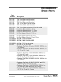
TROUBLESHOOTING . . . . . . . . . . . . . . . .6-1
Before Beginning . . . . . . . . . . . . . . . . . . . . . . . . . . . . . . . .6-2
A Few Words of Caution . . . . . . . . . . . . . . . . . . . . . . . . . .6-2
Identifying the Cause of a Problem . . . . . . . . . . . . . . . . . .6-3
Answering an Alarm . . . . . . . . . . . . . . . . . . . . . . . . . . . . .6-4
Control Problems . . . . . . . . . . . . . . . . . . . . . . . . . . . . . . . .6-5
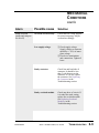
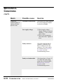
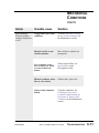
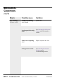
Mechanical Conditions . . . . . . . . . . . . . . . . . . . . . . . . . . .6-7
Checking and Replacing Switches . . . . . . . . . . . . . . . . . .6-15
Replacing the Contactor . . . . . . . . . . . . . . . . . . . . . . . . . .6-16
Checking and Replacing the RTD . . . . . . . . . . . . . . . . . .6-17
Replacing the Temperature Controller (TIC) . . . . . . . . . .6-18
Replacing Overload Modules . . . . . . . . . . . . . . . . . . . . . .6-19
Replacing Fuses . . . . . . . . . . . . . . . . . . . . . . . . . . . . . . . .6-20
Removing Pump Components . . . . . . . . . . . . . . . . . . . . .5-21
Checking the Pressure Switches . . . . . . . . . . . . . . . . . . . .6-22
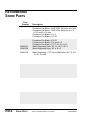
APPENDIX . . . . . . . . . . . . . . . . . . . . . .A-1
Customer Service . . . . . . . . . . . . . . . . . . . . . . . . . . . . . . .A-2
Maintenance Log . . . . . . . . . . . . . . . . . . . . . . . . . . . . . . .B-1
Pressure Tables . . . . . . . . . . . . . . . . . . . . . . . . . . . . . . . . .C-1
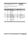
Control Settings . . . . . . . . . . . . . . . . . . . . . . . . . . . . . . . .D-1
PARTS
ii
AND
DIAGRAMS . . . . . . . . . . . .P/D-1
Series 1 Portable Chillers, TIC Control
UGH016/0500
INTRODUCTION
● Purpose of the User Guide . . . .1-2
● How the guide is organized . . . .1-2
● Your responsibilities as a user .1-2
● ATTENTION: Read this so
no one gets hurt . . . . . . . . . . .1-3
Series 1 Portable Chillers, TIC Control
UGH016/0500
1-1
PURPOSE OF
THE USER
GUIDE
This User Guide describes Conair’s Series 1 Water-cooled and
Air-cooled Portable Chillers and explains step-by-step how to
install, operate, maintain and repair this equipment.
HOW THE
GUIDE IS
ORGANIZED
Symbols have been used to help organize the User Guide and
call your attention to important information regarding safe
installation and operation.
YOUR
RESPONSIBILITY
AS A USER
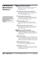
Before installing this product, please take a few moments to
read the User Guide and review the diagrams and safety information in the instruction packet. You also should review manuals covering associated equipment in your system. This
review won’t take long, and it could save you valuable installation and operating time later.
Symbols within triangles warn of conditions that could
be hazardous to users or could damage equipment.
Read and take precautions before proceeding.
1
Numbers within shaded squares indicate tasks or steps
to be performed by the user.
◆
A diamond indicates the equipment’s response to an
action performed by the user.
❒
●
An open box marks items in a checklist.
A shaded circle marks items in a list.
You must be familiar with all safety procedures concerning
installation, operation and maintenance of this equipment.
Responsible safety procedures include:
● Thorough review of this User Guide, paying particular
attention to hazard warnings, appendices and related diagrams.
● Thorough review of the equipment itself, with careful
attention to voltage sources, intended use and warning
labels.
● Thorough review of instruction manuals for associated
equipment.
● Step-by-step adherence to instructions outlined in this
User Guide.
1-2
INTRODUCTION
Series 1 Portable Chillers, TIC Control
UGH016/0500
We design equipment with the user’s safety in mind. You can
avoid the potential hazards identified on this machine by following the procedures outlined below and elsewhere in the
User Guide.
ATTENTION:
READ THIS
SO NO
ONE GETS HURT
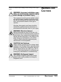
WARNING: Improper installation, operation, or servicing may result in equipment damage or personal injury.
This equipment should only be installed, adjusted, and serviced by qualified technical personnel who are familiar with the construction, operation, and potential hazards of this type of
machine.
All wiring, disconnects and fuses should be
installed by qualified electrical technicians in
accordance with electrical codes in your region.
Always maintain a safe ground. Do not operate
the equipment at power levels other than what
is specified on the machine serial tag and data
plate.
WARNING: Electrical hazard
Before performing any work on this item, disconnect and lock out electrical power sources to
prevent injury from unexpected energization or
startup.
CAUTION: Hot Surfaces
Always protect yourself from hot surfaces when
working on the Portable Chiller, especially when
working on or around the compressor and condenser. These devices can reach up to 160 °F
(71 °C). Allow these devices to cool before performing any maintenance or troubleshooting.
CAUTION: Ventilation hazard
The unit requires a clean and well ventilated
operating environment. Do not place anything
on top of the unit while operating. Units with
fans require unrestricted outlet air flow.
Water-cooled units require a minimum of one
foot clearance around the perimeter for serviceability. Air-cooled units require a minimum of two
feet clearance around the perimeter for serviceability and proper air flow.
UGH016/0500
Series 1 Portable Chillers, TIC Control
INTRODUCTION
1-3
DESCRIPTION
● What is the Portable Chiller? . . .2-2
● Typical Applications . . . . . . . . . .2-3
● Limitations . . . . . . . . . . . . . . . . .2-3
● How it Works: Water-cooled
Portable Chiller . . . . . . . . . . . .2-4
● How it Works: Air-cooled
Portable Chiller . . . . . . . . . . . .2-6
● Portable Chiller Features . . . . . .2-8
● Specifications . . . . . . . . . . . . .2-10
● Pump Curves . . . . . . . . . . . . . .2-12
Series 1 Portable Chillers, TIC Control
UGH016/0500
2-1
WHAT IS THE
PORTABLE
CHILLER?
The Conair Series 1 Portable Chillers provide self-contained
sources of chilled water and are available in either water- or
air-cooled models, ranging in sizes from 3.5 Hp to 40 Hp
(approximate capacities of 3.5 tons of refrigeration to 40 tons
of refrigeration). Pump selections are available to match most
process flow and pressure requirements.
The normal temperature range of discharge chilled water is
20 °F to 70 °F. For applications requiring 40 °F and lower
mix glycol with the water to the correct percentage.
The Air-cooled Portable Chiller A1 Models and Water-cooled
Portable Chiller W1 Models are designed to provide chilled
water for industrial applications requiring 24-hour-a-day performance. Units are totally self-contained for easy, economical
installation. All parts wetted by the process are non-ferrous.
To operate, simply connect the power source, process piping
and fill with water or ethylene or propylene glycol (but not
automotive antifreeze).
These chillers are ideal for machine-side cooling to maintain
process temperatures in an injection molding machine or
extruder and wherever you need a small, moveable cooling
unit. Nominal capacities range from 1.44 to 14.68 tons for the
water-cooled models and from 1.18 to 10.95 tons for the aircooled models. Capacities are based on standard pump sizes
and delivering 50 °F water.
Operation of these units differ only in the medium used to
remove heat from the refrigerant in the condensers. Watercooled models use 85 °F (29 °C) or lower cooling water from
a tower, well, or city service; air-cooled models use 95 °F
(35 °C) maximum ambient air.
Choose water-cooled portable chillers where tower water or
another inexpensive water source is available. Choose aircooled models for maximum portability of the unit. Watercooled models are equipped with brazed plate or tube-in-tube
condensers. Air-cooled models use aluminum-fin, copper-tube
condensers.
All standard voltages are available.
2-2
DESCRIPTION
Series 1 Portable Chillers, TIC Control
UGH016/0500
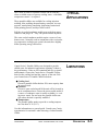
The Conair A1 and W1 Portable Chillers can be used anywhere a reliable source of process cooling water - with stable
temperature control - is required.
TYPICAL
APPLICATIONS
These portable chillers are available for cooling injection
molding, blow molding, thermoforming, extrusion, air compressors, metal plating, anodizing, degreasing, heatset/web
offset printing presses, and dryer after-coolers.
Roll the air-cooled condenser models next to the heat source
connect it and plug it in. They can operate almost anywhere.
The water-cooled condenser models require a source of condenser water. Normally used in conjunction with a recirculating evaporative cooling tower system, the units have slightly
better operating energy efficiencies.
Conair Series 1 Portable Chillers are designed to provide
chilled water for industrial applications requiring 24-hour-aday performance. Units are self-contained and easy to install
and maintain. Choose the Conair Series 1 Portable Chillers
based on the cooling load and the capacity of the unit. Pick
your Conair Series 1 Portable Chillers based on:
LIMITATIONS
● Cooling load
Choose a portable chiller that has 20% more capacity than
the process load.
● Location
Choose a water-cooled model if the unit will be located in
an air-conditioned area. Choose the water-cooled model if
a source of condenser water is readily available (i.e. cooling tower water). Do not locate the portable chiller outside unless the unit is specially modified.
● Temperature
The portable chiller needs to provide a cooling temperature less than 70 °F (21°C).
Use this information as a general guide. Consult your Conair
representative for assistance when choosing a Conair Portable
Chiller.
UGH016/0500
Series 1 Portable Chillers, TIC Control
DESCRIPTION
2-3
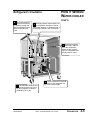
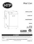
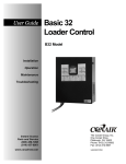
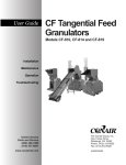
Process circulation
HOW IT WORKS:
WATER-COOLED
PORTABLE
CHILLER
1
Hot fluid from the
process enters the
chiller through the From
Process valve into the
pump reservoir.
2
is chilled in the
3 Fluid
evaporator and exits
through the to Process
valve and tube, returning to
the process.
2-4
DESCRIPTION
Pump draws water
from pump reservoir
and moves it through the
strainer and flow switch to
the evaporator.
Series 1 Portable Chillers, TIC Control
UGH016/0500
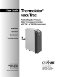
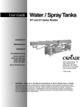
Refrigerant circulation
4 The liquid refrigerant
leaves the accumulator, passing through the
thermal expansion valve,
where it expands and
cools.
HOW IT WORKS:
WATER-COOLED
CONT’D
high pressure vapor travels from
3 The
the compressor through the coiled
condenser (where it is condensed into a
liquid) and is stored in the accumulator.
refrigerant
2 Vaporized
travels from evaporator to the compressor,
where the low pressure
vapor is compressed into
a high pressure vapor.
5
The evaporator extracts heat
1 from
the process fluid, caus-
Cooled refrigerant is metered
back into the exaporator for
the cycle to begin again.
ing the refrigerant to vaporize
(evaporate) into a gas.
UGH016/0500
Series 1 Portable Chillers, TIC Control
DESCRIPTION
2-5
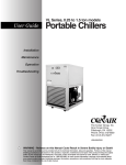
Process circulation
HOW IT WORKS:
AIR-COOLED
PORTABLE
CHILLER
1
Hot fluid from the
process enters the
chiller through the From
Process valve into the
pump reservoir.
is chilled in the
3 Fluid
evaporator and exits
through the To Process
valve and tube, returning to
the process.
2-6
DESCRIPTION
Pump draws fluid
from pump reservoir
and moves it through the
strainer and flow switch to
the evaporator.
2
Series 1 Portable Chillers, TIC Control
UGH016/0500
Refrigerant circulation
4
The liquid refrigerant
leaves the accumulator,
passing through the thermal expansion valve,
where it expands and
cools.
HOW IT WORKS:
AIR-COOLED
PORTABLE
CHILLER
3
The high pressure vapor
travels from the compressor
through the condenser (where
fans cool vapor into a liquid)
and liquid is stored in the
accumulator.
refrigerant
2 Vaporized
travels from evaporator to the compressor,
where the low pressure
vapor is compressed into
a high pressure vapor.
1
The evaporator extracts heat
from the process fluid, causing the refrigerant to vaporize
(evaporate) into a gas.
UGH016/0500
5
Cooled refrigerant is metered
back into the exaporator for
the cycle to begin again.
Series 1 Portable Chillers, TIC Control
DESCRIPTION
2-7
PORTABLE
CHILLER
FEATURES
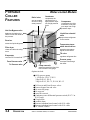
Water-cooled Models
Condenser
Relief valve
acts as a safety
device for refrigerant pressure.
compresses the
refrigerant from a
high pressure vapor
into a high pressure
liquid.
Compressor
compresses the refrigerant from a low pressure vapor into a high
pressure vapor.
Hot Gas Bypass valve
balances the load on the
chiller to meet the needs of
the process.
Liquid line solenoid
valve
pumps down refrigerant
to the receiver.
Receiver
stores the liquid refrigerant.
Filter dryer
Temperature transmitter electrical box
cleans and dries the refrigerant.
transmits temperature
signals to the control
TX valve
Evaporator
regulates refrigerant flow
cools the To Process fluid
Process pump
From Process valve
circulates fluid through
the chiller.
To Process valve
Pump reservoir
stores process fluid. View fluid
level on water level gauge
Options include:
● 60 Hz process pump
1 1/2 Hp for W1-1.5, W1-2
2 Hp for W1-3, W1-4
3 Hp for W1-5, W1-7.5, W1-10, W1-15
●
●
●
●
●
●
To Process and From Process valves
Process bypass line and valve
No reservoir/pump
No reservoir
Auto fill reservoir
Condenser water differential pressure switch (W1-7.5 to
W1-15 only)
● Visual alarm
● Audible alarm
● Remote/redundant hand control with 30 ft. cable
● Remote/redundant hand control with 50 ft. cable
● UL labeled controls
2-8
DESCRIPTION
Series 1 Portable Chillers, TIC Control
UGH016/0500
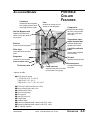
Air-cooled Models
Condenser
compresses the refrigerant
from a high pressure vapor
into a high pressure liquid.
PORTABLE
CHILLER
FEATURES
Fans
circulate air across the condenser to cool refrigerant
Compressor
compresses the refrigerant from a low pressure
vapor into a high pressure vapor.
Hot Gas Bypass valve
balances the load on the
chiller to meet the needs of
the process.
Temperature transmitter electrical box
Receiver
stores the liquid refrigerant.
transmits temperature
signals to the control
Filter dryer
Liquid line solenoid
valve
cleans and dries the refrigerant.
pumps down refrigerant
to the receiver.
Evaporator
TX valve
cools the To Process fluid
regulates refrigerant flow
From Process valve
Process pump
To Process valve
Pump reservoir
stores process fluid. View fluid
level on water level gauge
circulates fluid through
the chiller.
Options include:
● 60 Hz process pump
1 1/2 Hp for A1-1.5, A1-2.25
2 Hp for A1-3.25, A1-4
3 Hp for A1-5, A1-7.5, A1-10, A1-13
●
●
●
●
●
●
●
●
●
●
●
To Process and From Process valves
Process bypass line and valve
Condenser air filters
No reservoir/pump
No reservoir
Auto fill reservoir
Visual alarm
Audible alarm
Remote/redundant hand control with 30 ft. cable
Remote/redundant hand control with 50 ft. cable
UL labeled controls
UGH016/0500
Series 1 Portable Chillers, TIC Control
DESCRIPTION
2-9
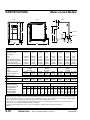
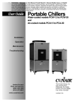
Water-cooled Models
SPECIFICATIONS
side
front
back
F
A
10.5 {267}
D
E
5.5 {140}
10 {254}
C
B
MODEL
Performance characteristics
Capacity✝ tons
Compressor Hp {kW}
Pump Hp {kW}
60 Hz
50 Hz
Chilled water flow‡ gpm {lpm}
Chilled water pressure§ psi {bar}
Reservoir capacity gal {l}
Condenser water flow gpm {lpm}
Dimensions in {mm}
A-Height
B-Width
C-Length
D-Height to condenser out
E-Height to condenser in
F-Distance to valve
Weight lb {kg}
Installed
Shipped
Utility requirements
Process connections NPT in
Condenser water NPT in
Power consumption amps
230V/3 phase/60hz*
220V/3 phase/50hz
460V/3 phase/60hz*
575V/3 phase/60hz*
9 {229}
W1-1.5
W1-2
W1-3
W1-4
W1-5
W1-7.5
W1-10
W1-15
1.44
1.5 {1.1}
1.93
2 {1.5}
3.23
3 {2.2}
4.44
4 {3}
5.00
5 {3.7}
7.09
7.5 {5.6}
10.22
10 {7.5}
14.68
15 {11}
0.75 {0.6}
1.5 {1.1}
6.9 {25.1}
27.8 {1.9}
8.0 {30.3}
5.0 {18.9}
0.75 {0.6}
1.5 {1.1}
4.6 {17.4}
29.9 {2.1}
15 {57}
6.4 {24.2}
1.5 {1.1}
2 {1.5}
12.0 {45.4}
41.6 {2.9}
15 {57}
16.7 {63.2}
1.5 {1.1}
2 {1.5}
17.0 {64.3}
34.8 {2.4}
25 {95}
24.1 {91.2}
49 {1245}
34 {864}
39.5 {1003}
37 {940}
38.5 {978}
31 {787}
32.5 {826}
4 {102}
420 {190}
550 {249}
1 {.8}
1 {.8}
1.5 {1.1}
2 {1.5}
7.8 {29.5} 10.7 {40.5}
32.9 {2.3} 31.8 {2.2}
15 {57}
15 {57}
10.3 {39.0} 14.2 {53.7}
38.5 {978}
32.5 {826}
585 {265}
755 {342}
585 {265}
755 {342}
49 {1245}
34 {864}
45.5 {1156}
38.5 {978}
32.5 {826}
840 {381}
1010 {458}
38 {965}
32 {813}
41.3 {1049}
35 {889}
4.5 {114}
840 {381}
1010 {458}
1080 {490}
1250 {567}
1
1
run
9.5
13.1
4.5
3.6
full
15.3
19.1
6.9
5.5
run
10.2
13.8
4.9
3.9
full
15.6
19.4
7.1
5.7
run
15.1
17.8
7.3
5.8
full
24.4
27.5
11.1
8.9
run
18.7
22.5
9.1
7.3
full
29.4
33.6
13.3
10.7
run
22.5
24.3
10.9
8.7
full
36.3
38.6
16.4
13.1
run
29.2
31.3
14.2
11.4
full
44.7
47.4
20.2
16.2
1.5 {1.1}
2 {1.5}
2 {1.5}
2 {1.5}
24.5 {92.7} 35.2 {133.2}
29.3 {2.0}
32.3 {2.2}
25 {95}
25 {95}
31.7 {120} 45.4 {172}
61 {1549}
34 {864}
55 {1397}
41.3 {1049 41.3 {1049}
35 {889}
35 {889}
1090 {494}
1260 {572}
1.5
1.5
run
35.0
37.4
17.1
13.7
full
56.0
59.1
25.3
20.2
1095 {497}
1265 {574}
run
44.8
46.8
22.0
17.6
full
79.0
82.1
35.7
28.5
SPECIFICATION NOTES
✝ Based on 50 °F (10 °C) water temperature (100% water) leaving the chiller, standard pump selections, 85 °F (27 °C) condenser water supply
@ 25 psi minimum, for the 60 Hz units. For the 50 Hz units, multiply the capacity by 0.8 Consult factory for other conditions. Capacity ratings
are (+-) 5% based on compressor manufacturer’s ratings and are subject to change without notice.
‡ Based on 50° F (10 °C) water temperature leaving the chiller and 60 °F (16 °C) water temperature returning to the chiller (except W1-1.5
which has 55 °F (13 °C) water temperature returning to the chiller).
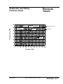
§ Pressure at pump discharge. See Pressure Tables in the Appendix for Evaporator and Condenser pressure drops.
* Optional
2-10
DESCRIPTION
Series 1 Portable Chillers, TIC Control
UGH016/0500
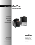
Air-cooled Models
SPECIFICATIONS
front
back
side
A
10.5 {267}
5.5 {140}
MODEL
Performance characteristics
Capacity✝, tons
Compressor Hp{kW}
Pump Hp {kW}
60 Hz
50 Hz
Chilled water flow‡, gpm {lpm}
Chilled water pressure§, psi {bar}
Reservoir capacity, gal {l}
Condenser fans
Condenser fan power Hp {kW}
Condenser air flow
ft3/min {liters/min}
Dimensions in {mm}
A-Height
B-Width
C-Length
Weight lb {kg}
Installed
Shipped
Utility requirements
Process connections in
Power consumption amps
230V/3 phase/60hz*
220V/3 phase/50hz*
460V/3 phase/60hz
400v/3 phase/50hz*
575V/3 phase/60hz*
10 {254}
C
B
9 {229}
A1-1.5
A1-2.25
A1-3.25
A1-4
A1-5
A1-7.5
A1-10
A1-13
1.18
1.5 {1.1}
1.79
2.25 {1.7}
2.77
3.25 {2.4}
3.62
4 {3}
4.27
5 {3.7}
6.06
7.5 {5.6}
8.75
10 {7.5}
10.95
13 {}
0.75 {0.6}
1.5 {1.1}
5.7 {21.6}
29.6 {2.0}
8.8 {33.3}
1
0.17 {0.13}
1050
{29,732}
0.75 {0.6}
1.5 {1.1}
8.6 {32.6}
28.5 {2.0}
15 {57}
2
0.17 {0.13}
1704
{48,250}
1 {.8}
1.5 {1.1}
6.7 {25.4}
35.9 {2.5}
15 {57}
2
0.17 {0.13}
2420
{68,525}
1 {.8}
2 {1.5}
8.7 {32.9}
33.9 {2.3}
15 {57}
2
0.25 {0.19}
4237
{119,975}
1.5 {1.1}
2 {1.5}
10.2 {38.6}
42.4 {2.9}
15 {57}
2
0.25 {0.19}
4237
{119,975}
1.5 {1.1}
2 {1.5}
14.5 {54.9}
36.9 {2.5}
25 {95}
2
0.5 {0.4}
5300
{150,075}
1.5 {1.1}
2 {1.5}
21.0 {79.5}
31.6 {2.2}
25 {95}
2
0.5 {0.4}
5300
{150,075}
2 {1.5}
2 {1.5}
26.3 {99.6}
36.1 {2.5}
25 {95}
4
0.5 {0.4}
9800
{277,505}
49 {1245}
34 {864}
39.5 {1003}
49 {1245}
34 {864}
45.5 {1156}
610 {277}
750 {340}
830 {376}
1000 {454}
run
11.0
14.7
5.3
7.7
4.2
run
full
13.3 20.8
17.1 24.8
6.5
9.4
9.0 12.4
5.2
7.5
full
19.6
23.6
8.9
11.8
7.1
53.5 {1359}
34 {864}
55 {1397}
830 {376}
1000 {454}
run
18.6
21.5
9.0
11.4
7.2
1
full
32.2
35.5
14.6
17.8
11.7
1030 {467}
1200 {544}
run
23.7
27.7
11.6
14.8
9.3
full
33.3
37.6
15.1
18.8
12.1
71 {1524}
34 {864}
55 {1397}
1030 {467}
1200 {544}
run
27.8
29.9
13.5
16.0
10.8
full
40.1
42.6
18.2
21.3
14.5
1230 {558}
1400 {635}
run
38.6
41.2
18.9
22.2
15.1
full
47.2
50.0
21.4
25.0
17.1
1230 {558}
1600 {726}
run
47.2
50.2
23.2
27.2
18.6
1.5
full
62.7
66.1
28.4
33.0
22.7
75 {1905}
34 {864}
55 {1397}
1440 {653}
1800 {816}
run
57.4
60.0
28.3
32.6
22.6
full
76.9
79.9
34.8
40.0
27.8
SPECIFICATION NOTES
✝ Based on 50 °F (10 °C) water temperature (100% water) leaving the chiller, standard pump selections, 95 °F (35 °C) ambient air conditions for
the 60 Hz units. For the 50 Hz units, multiply the capacity by 0.8. Consult factory for other conditions. Capacity ratings are (+-) 5% based on
compressor manufacturer’s ratings and are subject to change without notice.
‡ Based on 50 °F (10 °C) water temperature leaving the chiller and 60 °F (16 °C) water temperature returning to the chiller (except A1-1.5 and
A1-2.25 which have 55 °F (13 °C) water temperature returning to the chiller).
§ Pressure at pump discharge. See Pressure Tables in the Appendix for Evaporator and Condenser pressure drops.
* Optional
UGH016/0500
Series 1 Portable Chillers, TIC Control
DESCRIPTION
2-11
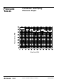
PUMP CURVES
Pressure (psi)
60 HZ PUMP PERFORMANCE CURVES
Flow Rate (gpm)
Pressure (psi)
50 HZ PUMP PERFORMANCE CURVES
Flow Rate (gpm)
2-12
DESCRIPTION
Series 1 Portable Chillers, TIC Control
UGH016/0500
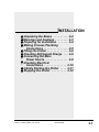
INSTALLATION
● Unpacking the Boxes . . . . . . . . . .3-2
● Warnings and Cautions . . . . . . . . .3-3
● Preparing for Installation . . . . . . .3-4
● Making Process Plumbing
Connections . . . . . . . . . . . . . . . .3-5
● Filling the Chiller . . . . . . . . . . . . . .3-6
● Checking Refrigerant Charge . . . .3-8
● Connecting the Main
Power Source . . . . . . . . . . . . . . .3-9
● Checking Electrical
Connections . . . . . . . . . . . . . . .3-10
● Initially Starting the Chiller . . . . .3-11
● Stopping the Chiller . . . . . . . . . .3-12
Series 1 Portable Chillers, TIC Control
UGH016/0500
3-1
UNPACKING THE
BOXES
The portable chiller comes fully assembled in a single crate.
CAUTION: Lifting hazard
The Series 1 Portable Chillers are designed to
easily roll on casters. If, for some reason you
need to lift the chiller, take all precautions to
avoid personal injury or damage to the chiller.
Lift the chiller using a forklift or hoist with straps
that have peen positioned at the chillers’ center
of gravity. Do not try to lift the unit manually.
1
Carefully uncrate the chiller
and its components.
2
Remove all packing material, protective paper,
tape, and plastic. compare contents to the shipping papers
to ensure that you have all the parts.
3
Carefully inspect all components to make sure
no damage occurred during shipping. If any damage is
found, notify the shipping agent immediately. Check all
wire terminal connections, bolts, and any other electrical
connections, which may have come loose during shipping. Check for pinched wires and kinked hoses.
3
Record serial numbers and specifications
in the blanks provided on the back of the User Guide’s
title page. This information will be helpful if you ever
need service or parts.
3-2
INSTALLATION
Series 1 Portable Chillers, TIC Control
UGH016/0500
WARNING: Improper installation, operation, or servicing may result in equipment damage or personal injury.
This equipment should only be installed, adjusted, and serviced by qualified technical personnel who are familiar with the construction, operation, and potential hazards of this type of
machine.
WARNINGS
CAUTIONS
AND
All wiring, disconnects and fuses should be
installed by qualified electrical technicians in
accordance with electrical codes in your region.
Always maintain a safe ground. Do not operate
the equipment at power levels other than what
is specified on the machine serial tag and data
plate.
CAUTION: Hot Surfaces
Always protect yourself from hot surfaces when
working on the Portable Chiller, especially when
working on or around the compressor and condenser. These devices can reach up to 160 °F
(71 °C). Allow these devices to cool before performing any maintenance or troubleshooting.
CAUTION: Ventilation hazard
The unit requires a clean and well ventilated
operating environment. Do not place anything
on top of the unit while operating. Units with
fans require unrestricted outlet air flow.
Water-cooled units require a minimum of one
foot clearance around the perimeter for serviceability. Air-cooled units require a minimum of two
feet clearance around the perimeter for serviceability and proper air flow.
UGH016/0500
Series 1 Portable Chillers, TIC Control
INSTALLATION
3-3
PREPARING FOR
INSTALLATION
Plan the location for the chiller and prepare the area properly.
Position the Chiller as close to the process machine as possible. Place the chiller in position near the process machine so
that fluid lines can be connected from the process machine to
the chiller and back.
Chiller
Process machine
Alternate
locations
Make sure the area where the chiller is installed has:
● A grounded power source.
Check the chiller’s serial tag for the correct amps, voltage, phase, and cycle. All wiring should be completed by
qualified personnel and comply with your region’s electrical codes.
● Clearance for safe operation and maintenance.
Make sure there is two feet clearance around the chiller
for proper operation, maintenance, and servicing. After
positioning, lock casters to prevent chiller from moving.
24 inches
(610 mm)
24 inches
(610 mm)
24 inches
(610 mm)
24 inches
(610 mm)
● Available water source.
If installing a water-cooled unit, makes sure water source
is plumbed to chiller installation location. High points in
plumbing require vent valves; low points require drain
valves.
3-4
INSTALLATION
Series 1 Portable Chillers, TIC Control
UGH016/0500
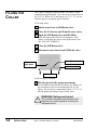
Warm fluid from your process enters the chiller at the From
Process valve and chilled fluid returns to the process equipment through the To Process valve.
1
Remove the shipping plastic pipe plug from
the female connections on the back of the portable chiller.
2
Make sure the male pipe threads are clean
MAKING
PROCESS
PLUMBING
CONNECTIONS
and new.
3
4
Wrap threads with Mylar or Teflon tape.
Connect the From Process valve and tubing
on the back of the chiller to the From Process tubing.
Start by hand until the threads engage and then tighten
with a pipe wrench. Tighten only enough to prevent leaks;
do not over-tighten!
5
Connect the To Process valve and tubing on
the back of the chiller to the return tubing. Start by hand
until the threads engage and then tighten with a pipe
wrench. Tighten only enough to prevent leaks; do not
over-tighten!
For the Water-cooled Chillers connect the water source for
cooling to the Condenser Water inlet on the back of the chiller.
Connect the Condenser Water outlet for returning water.
back view
Condenser
Water Outlet
(water-cooled only)
Condenser
Water Inlet
(water-cooled only)
From Process valve
To Process valve
UGH016/0500
Series 1 Portable Chillers, TIC Control
INSTALLATION
3-5
The Chiller is shipped without coolant. The chiller is filled
manually during installation. Use water as the coolant down to
40 °F (4 °C). Below 40 °F and down to 20 °F (-7 °C), use an
ethylene glycol or propylene glycol solution.
FILLING THE
CHILLER
To fill with water:
1
2
3
Attach water hose to Fill/Drain valve.
Close the To Process and From Process valves.
Open the Fill/Drain valve and fill chiller
to the fill mark on the Water Level sight glass. If the
chiller is overfilled, the excess water spills out the vent
tube. DO NOT OVERFILL.
4
5
Close the Fill/Drain valve.
Disconnect water hose from Fill/Drain valve.
From Process valve
Water Level
sight glass
To Process valve
Fill/Drain valve
To fill with glycol solution:
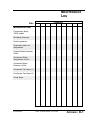
1
Mix the glycol to the proper percentage.
Use the table to determine the percentage (by volume) of
glycol needed for the process temperature (in °F) you
require. Do not choose a temperature below 15 °F (-9 °C).
Mix the proper percentage of glycol with water.
WARNING: Refrigerant hazard
Only certified refrigerant technicians should
examine and correct problems involving the
refrigerant circuit.
3-6
INSTALLATION
Series 1 Portable Chillers, TIC Control
UGH016/0500
FILLING THE
CHILLER
Glycol, % by Volume
CONT’D
Temperature of Process Fluid °F
2
3
Close the To Process and From Process valves.
Open the Fill/Drain valve and fill chiller
to the fill mark on the Water Level gauge. If the chiller is
overfilled, the excess fluid spills out the vent tube. DO
NOT OVERFILL.
4
5
Close the Fill/Drain valve.
Check the coolant level.
Once the chiller is turned on, the coolant level may drop
as the coolant begins to circulate, filling the connected
plumbing. Check the coolant level on the back of the
chiller. The water level shows on the water level gauge.
Make sure water level is filled to the mark on the gauge.
6
Change the minimum operating temperature
range to the correct setting for the percent glycol used.
See Setting the To Process Low Limit, in the Operations
section.
UGH016/0500
Series 1 Portable Chillers, TIC Control
INSTALLATION
3-7
CHECKING
REFRIGERANT
CHARGE
All chillers are fully charged with refrigerant at the factory.
Your chiller’s model nameplate identifies the type and amount
of total refrigerant charge required.
Check refrigerant charge while the chiller is running. Check
the refrigerant charge through the sight glass. Open the side
door of the Chiller. Use a flashlight, if necessary, and check
the liquid-line sight glass:
● Under normal load conditions, the refrigerant should
be clear.
● Under low load conditions, when the hot-gas bypass
valves are operating, bubbles may be visible in the
sight glass. This is normal.
If the charge is low contact Conair service or have a local, certified refrigeration technician add refrigerant to the system.
WARNING: Refrigerant hazard
Only certified refrigerant technicians should
examine and correct problems involving the
refrigerant circuit.
Sight glass
3-8
INSTALLATION
Series 1 Portable Chillers, TIC Control
UGH016/0500
WARNING: Improper installation, operation, or servicing may result in equipment damage or personal injury.
This equipment should only be installed, adjusted, and serviced by qualified technical personnel who are familiar with the construction, operation, and potential hazards of this equipment
CONNECTING
THE MAIN
POWER SOURCE
All wiring, disconnects and fuses should be
installed by qualified electrical technicians in
accordance with electrical codes in your region.
Always maintain a safe ground. Do not operate
the equipment at power levels other than what
is specified on the machine serial tag and data
plate.
WARNING: Electrical hazard
Before performing any work on this item, disconnect and lock out electrical power sources to
prevent injury from unexpected energization or
startup.
1
2
Open the chiller’s electrical enclosure.
Connect the power wires to the terminals
as indicated on the wiring diagrams
that came with your machine. Route
the power cable through the hole in
the side of the chiller to the electrical
enclosure.
3
Check terminal screws to
make sure wires are secure. Gently
tug each wire; if wire is loose, use a
screwdriver to tighten the terminal.
4
The 575V, 1 1/2 - 4 Hp
units utilize a transformer;
power wires must be connected to the line side of
the transformer.
Grounding lug
Connect the ground wire to grounding lug.
UGH016/0500
Series 1 Portable Chillers, TIC Control
INSTALLATION
3-9
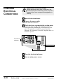
CHECKING
ELECTRICAL
CONNECTIONS
WARNING: Electrical hazard
Before performing any work on this item, disconnect and lock out electrical power sources to
prevent injury from unexpected energization or
startup.
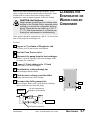
1
2
Open electrical enclosure.
Connect the power cable
to the main line connection.
3
Check the short-to-ground with an ohm meter.
Connect the ohm meter to each of the three terminal
screws and to the grounding lug. Test all three for resistance. The minimum resistance to ground should be
1megohm. If it resistance is less that 1 megohm, there is a
leak in the system.
Test each for
resistance
Grounding lug
4
5
3-10
INSTALLATION
Close the electrical enclosure.
Turn on main power source.
Series 1 Portable Chillers, TIC Control
UGH016/0500
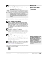
1
Turn on main power source.
The control boots up and the screen displays the temperature of the fluid going to the process.
WARNING: Initial startup
INITIALLY
STARTING THE
CHILLER
Do not press any buttons after initially applying
power to the Chiller. Let the Chiller set, undisturbed, for a minimum of 8 hours before starting
the Chiller. This is necessary to allow the
crankcase heater to warm properly, and to prevent the refrigerant from pooling in the compressor.
After the initial 8-hour minimum warmup, continue with startup:
2
Press the Start Chiller button.
Check the Pump and Compressor lights on the control
panel; they should turn on and off as the pump and compressor cycle on and off. The To Process temperature displays on the control. The To Process temperature is realtime temperature. It should change as the chiller runs and
cools the fluid.
3
Check the rotation of the pump.
If pump is not turning, disconnect main power to chiller,
swap any two incoming power wires; reapply main power.
Check for leaks inside the chiller cabinet; fix any leaks
and dry the inside of the chiller before proceeding.
4
Check the compressor.
If the compressor is running backwards, disconnect the
Chiller from the main power supply, switch any two
incoming main power leads, and reapply main power supply. Wait three minutes. The compressor should now be
running in the proper direction.
5
Check the sight glass on the back of the chiller.
If the fluid level is low, follow the steps to add fluid. See
Filling the Chiller in the Installation section.
When the compressor is shut
off it cannot be turned on
again for three minutes. This
allows temperatures and
pressure in the chiller to
equalize, making restart easier, and prolonging the life of
the chiller.
If the chiller is not working properly at any time, press the red
Stop button to turn off the chiller.
UGH016/1200
Series 1 Portable Chillers, TIC Control
INSTALLATION
3-11
STOPPING THE
CHILLER
To stop the chiller, press the Stop Chiller button on the control
panel.
NOTE: When you press the Stop Chiller button, the pump and
compressor both stop. If you want to restart immediately by
pressing the Start Chiller button, the pump will turn on but the
compressor will not turn on for three minutes. The Process
Pump light on the control panel will light immediately. After
three minutes the compressor turns on and the Compressor
light on the control panel lights. This allows temperatures and
pressure to equalize, making restart easier, and prolonging the
life of the chiller.
If the chiller is not working properly at any time, stop the
chiller and refer to the Troubleshooting section. If you do not
encounter any problems, proceed to the Operation section.
3-12
INSTALLATION
Series 1 Portable Chillers, TIC Control
UGH016/0500
OPERATION
● TIC Control Features . . . . . . . . .4-2
● Before Starting . . . . . . . . . . . . . .4-3
● Starting/Stopping the Chiller . . .4-4
● Changing Settings . . . . . . . . . . .4-5
● Changing the Setpoint
Temperature . . . . . . . . . . . . . .4-6
● Changing Temperature Scale . .4-7
● Changing Auto Tune Mode . . . .4-7
● Setting the To Process
Low Limit . . . . . . . . . . . . . . . . .4-8
Series 1 Portable Chillers, TIC Control
UGH016/0500
4-1
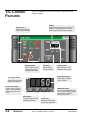
TIC CONTROL
FEATURES
The TIC control lets you view the status of the chiller and
change settings.
Display
System lights
4-digit LED screen shows To Process temperature, new settings and run modes.
Indicator light shows hot gas unloading.
Light when compressor,
pump or alarm activates
System buttons
Quick text
Control buttons
Press to start and stop
chiller and to silence
optional audible alarm
Follow steps to
change setpoints
Press to access menus,
enter data, and to scroll
4-Digit LED display
Unloading indicator
Shows status, settings
and run modes.
Lights when the hot gas
bypass is unloading.
Menu Access button
Mode/Enter button
Press to enter or change
setpoint, to exit the menu,
and to index to the next
menu.
Press to enter parameter selections, access operating modes,
silence alarms, and index
through menu items.
Raise button
Increases values, hold for
fast-step progression.
4-2
OPERATION
Lower button
Decreases values; hold
for fast-step progression.
Series 1 Portable Chillers, TIC Control
UGH016/0500
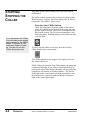
Before you start daily operation of the chiller, you need to
perform scheduled preventative maintenance. Necessary maintenance is describe in the Maintenance section of this Users
Guide.
BEFORE
STARTING
WARNING: Electrical hazard
Be sure that power to the chiller is OFF when
doing any maintenance on the chiller. Follow all
safety rules when performing any maintenance
on this equipment.
Daily maintenance includes:
●
●
●
●
●
Checking electrical connections
Checking process fluid level in the pump tank
Checking the condenser coil for debris
Verifying pump discharge pressure
Inspecting piping for leaks
NOTE: The daily, weekly, monthly, and semi-annual maintenance procedures are detailed in the Maintenance section. Go
there for detailed preventative maintenance.
Before starting the Chiller be sure to:
● Open the To Process valve
to the full open position.
● Open the From Process valve
to the 3/4 open position. You will need to adjust this
valve when the chiller is running to obtain the desired
pump discharge pressure. To find the approximate
water flow, refer to the Pump Curves in Description
section.
From Process valve
To Process valve
● Check that the casters are locked.
UGH016/0500
Series 1 Portable Chillers, TIC Control
OPERATION
4-3
STARTING/
STOPPING THE
CHILLER
Plug in the power cord to restore power after any required
maintenance.
The chiller control automatically performs its bootup routine.
When bootup is complete, the screen displays the To Process
temperature. The chiller is ready to run.
Press the Start Chiller button.
If you disconnect the Chiller
from the main power supply
and reconnect it, the Chiller
needs 15 minutes for the
crankcase heater to warm
up. You can not use the
Chiller during this time.
Check the Pump and Compressor lights on the control
panel; they should turn on and off as the pump and compressor cycle on and off. The To Process temperature displays on the control. The To Process temperature is realtime temperature. It should change as the chiller runs and
cools the fluid.
To safely stop the chiller at any time, press the red Stop
Chiller button on the control panel.
The chiller remains on, but stopped. The display screen on
the control remains on.
NOTE: When you press the Stop Chiller button, the pump and
compressor both stop. If you want to restart immediately by
pressing the Start Chiller button, the pump will turn on but the
compressor will not turn on for three minutes. The Process
Pump light on the control panel will light immediately. After
three minutes the compressor turns on and the Compressor
light on the control panel lights.
4-4
OPERATION
Series 1 Portable Chillers, TIC Control
UGH016/0500
The control allows you to change four settings:
● Temperature Setpoint
The temperature you want the To Process liquid
● Temperature Scale
Choose to display temperature in degrees Fahrenheit or
Celsius.
● Auto Tune
Helps maintain the temperature setpoint without overshooting.
● To Process Low Limit
Set when need to chill fluid below 40 °F (4 °C) and
down to 20 °F (-7 °C). Set this limit when using glycol
to chill.
CHANGING
SETTINGS
All other settings are set at the factory. You should not change
any other settings. If you accidentally change any other setting, refer to the control manual that you received with your
chiller and see Control Settings, in the Appendix. If you have
any problems or questions, call your Conair Service representative.
The current To Process temperature displays on the screen
when the chiller is turned on. As the temperature changes, the
number on the display changes.
The setpoint temperature is the temperature you want the
water to be exiting the chiller at the To Process valve.
CHANGING THE
SETPOINT
TEMPERATURE
To set the temperature setpoint:
1
Press Menu button once.
The display flashes SP, and the current setpoint
temperature.
2
Press the Up/Down arrows
to raise and lower the setpoint temperature. Each
time you press the arrow the temperature
changes one unit. Stop when you reach the temperature you want.
3
Press the Mode/Enter button
to accept the new setpoint temperature. The display returns to the actual process temperature.
UGH016/0500
Series 1 Portable Chillers, TIC Control
To return to the To Process
Temperature screen from
any other screen, press and
hold the
button for at
least 5 seconds until the
temperature displays.
OPERATION
4-5
CHANGING
TEMPERATURE
SCALE
The default temperature scale for the control is Fahrenheit (F).
You can change the scale to Celsius (C):
1
Press Menu button until DISP shows
on the screen.
2
Press the Enter button.
The current temperature scale displays (F or C)
and is flashing.
3
Press the Up/Down arrows
to move to the other scale. If the current temperature scale is Fahrenheit, pressing the arrow
moves you to C; if the current temperature scale
is Celsius, pressing the arrow moves you to F.
4
Press the Menu button
to accept the new temperature scale and displays
the process temperature.
CHANGING TO
AUTO TUNE
MODE
Use the Auto Tune Mode to maintain the temperature setpoint
without overshooting it. When initiating Auto Tune Mode the
actual temperature (temperature of the water exiting the
Chiller) must at least 20° warmer than the current setpoint
temperature. In order to guarantee this, run the chiller for several minutes until the To Process temperature is 40 °F with no
load on the Chiller.
To initiate the Auto Tune mode:
To return to the To Process
Temperature screen from
any other screen, press and
hold the
button for at
least 5 seconds until the
temperature displays.
4-6
OPERATION
1
Press Enter button and hold
2
Use the Up/Down arrows to scroll
3
Press the Enter button.
for 3 seconds. FOP displays on the screen.
until STBY (standby) displays.
STBY flashes on the screen alternately with the
current To Process temperature.
Series 1 Portable Chillers, TIC Control
UGH016/0500
4
Press the Menu button.
SP displays, flashing alternately with the current setpoint temperature.
5
Use the Up/Down arrows to change
the setpoint temperature. Each time you press
an arrow, the displayed number changes one
unit.
6
CHANGING
AUTO TUNE
MODE
CONT’D
Press Enter button.
The screen displays STBY and the new number.
7
Press Enter button and hold
for 3 at least seconds until FOP displays on the
screen.
8
Apply a load to the Chiller.
9
Use the Up/Down arrows to scroll
until ATUN displays on the screen.
10 Press the Enter/Mode button once.
To return to the To Process
Temperature screen from
any other screen, press and
hold the
button for at
least 5 seconds until the
temperature displays.
The screen flashes ATUN. When auto tuning is
done the screen displays STBY.
11 Press Enter button and hold
for 3 at least seconds until FOP displays on the
screen.
12 Use the Up/Down arrows to scroll
to NOR on the screen.
13 Press Enter button.
Initiating Auto Tune is complete.
UGH016/0500
Series 1 Portable Chillers, TIC Control
OPERATION
4-7
SETTING THE TO
PROCESS LOW
LIMIT
The default low temperature limit for the To Process fluid is
set at the factory at 40 °F. This temperature limit is the lowest
temperature for the chilled fluid leaving the Chiller. If you
want to cool fluid below 40 °F (4 °C) and down to 20 °F
(-7 °C), you need to fill the chiller with the proper percentage
of glycol solution. See Filling the Chiller, in the Installation
section.
After the Chiller is filled with the proper percentage of glycol
solution, you need to set the minimum operating temperature
on the control. Use the temperature you chose when selecting
the percent glycol.
To set the To Process low limit on the control:
1
Press Menu button until INP shows
on the screen.
2
To return to the To Process
Temperature screen from
any other screen, press and
hold the
button for at
least 5 seconds until the
temperature displays.
Press the Enter button until SPLL
displays on the screen. SPLL flashes, along with
the current low limit temperature.
3
Press the Up/Down arrows
to change the temperature to the required number.
4
Press the Menu button
to accept the new temperature.
If you want to change from using a glycol solution back
to using water in your chiller, you need to change the low
limit temperature to 40 °F (4 °C). Follow the steps listed
here to set the To Process low limit to 40.
4-8
OPERATION
Series 1 Portable Chillers, TIC Control
UGH016/0500
MAINTENANCE
● Maintenance Features . . . . . . . .5-2
● Warnings and Cautions . . . . . . .5-3
● Preventative Maintenance
Schedule . . . . . . . . . . . . . . . . .5-4
● Checking the Refrigerant
Charge . . . . . . . . . . . . . . . . . . .5-6
● Cleaning the Evaporator or
Water-cooled Condenser . . . .5-7
● Cleaning the Air-cooled
Condenser . . . . . . . . . . . . . . . .5-8
● Checking Electrical
Connections . . . . . . . . . . . . . .5-9
● Checking Reservoir Level . . . .5-10
Series 1 Portable Chillers, TIC Control
UGH016/0500
5-1
MAINTENANCE
FEATURES
Conair Series 1 Portable Chillers need regular, scheduled
maintenance for peak performance.
To maintain the best performance of the chiller, it must be
cleaned and inspected regularly. Maintenance includes a daily,
monthly, and semi-annual schedule.
Use this maintenance schedule as a guide. You may need to
shorten the time of the maintenance schedule, depending on
how often you use the chiller. Among the features that require
preventative maintenance are:
●
●
●
●
●
●
5-2
MAINTENANCE
the refrigerant system
electrical cables, terminals, and control lights
the condenser
process fluid level
evaporator
Cooling water treatment system (if used)
Series 1 Portable Chillers, TIC Control
UGH016/0500
Follow all cautions and warnings when working on the equipment.
WARNING: Improper installation, operation, or servicing may result in equipment damage or personal injury.
WARNING AND
CAUTIONS
This equipment should only be installed, adjusted, and serviced by qualified technical personnel who are familiar with the construction, operation, and potential hazards of this type of
machine.
All wiring, disconnects, and fuses should be
installed by qualified electrical technicians in
accordance with electrical codes in your region.
WARNING: Electrical hazard
Before performing any work on this item, disconnect and lock out electrical power sources to
prevent injury from unexpected energization or
startup. Be sure that power to the chiller is OFF
when doing any maintenance on the chiller.
Follow all safety rules when performing any
maintenance on this equipment.
CAUTION: Hot Surfaces
Always protect yourself from hot surfaces when
working on the Portable Chiller, especially when
working on or around the compressor and condenser. These devices can reach up to 160 °F
(71 °C). Allow these devices to cool before performing any maintenance or troubleshooting.
WARNING: Refrigerant hazard
Only certified refrigerant technicians should
examine and correct problems involving the
refrigerant circuit.
UGH016/0500
Series 1 Portable Chillers, TIC Control
MAINTENANCE
5-3
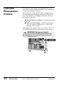
PREVENTATIVE
MAINTENANCE
SCHEDULE
● Daily, or as often as needed
❒ Checking electrical connections
Make sure electrical connections are properly seated.
See Checking Electrical Connections, in the
Maintenance section.
❒ Checking process fluid level in the pump tank
Check the process fluid level in the water level gauge
on the back of the chiller. If low, see Filling the
Chiller, in the Installation section.
To maintain the best performance, follow the maintenance schedule and record
information in the
Maintenance Log in the
Appendix.
❒ Verifying pump discharge pressure
While the pump is running, check that the pump pressure gauges are within range. To change the pressure
open or close the From Process valve.
❒ Inspecting piping for leaks
Check to see that pipes are not leaking. Look for
standing water on the floor or inside the chiller cabinet.
❒ Inspecting the condenser coil for debris
(air-cooled models only) Remove the wire mesh side
panel in front of the condenser coil. Remove any
debris from the coils.
● Weekly, or as often as needed
❒ Checking temperature and pressure readings
Check that the temperature and pressure display on the
control screen, and that the pressure gauge indicates
normal operation.
❒ Checking efficiency
Review the performance data on the Maintenance Log
found in the Appendix. If you notice a decrease in efficiency over time, check all heat transfer surfaces of the
evaporator and condenser for fouling. Clean as needed.
❒ Checking refrigerant site glass
There should not be any bubbles. See Checking
Refrigerant Charge, in the Maintenance section.
❒ Checking reservoir level
Check the water level gauge on the back of the chiller.
If fluid level is low, fill. See Checking Reservoir Level,
in the Maintenance section.
5-4
MAINTENANCE
Series 1 Portable Chillers, TIC Control
UGH016/0500
● Monthly
❒ Inspecting cooling water treatment system
If your chiller uses a cooling water treatment system,
maintain proper chemical levels and follow the recommendations of your water treatment specialist. Change
water in the reservoir tank monthly.
PREVENTATIVE
MAINTENANCE
SCHEDULE
❒ Cleaning
Wipe all external surfaces to maintain performance.
❒ Inspecting condenser
Check the condenser for adequate air flow or water
flow. Check the condenser face for dirt and clogging.
If dirt or clogs are present, clean the condenser. See
Cleaning the Evaporator or Water-cooled Condenser,
and Cleaning the Air-cooled Condenser, in the
Maintenance section. If your unit has an optional filter
at the air inlet of the Air-cooled condenser coil, check,
clean, and replace as needed.
To maintain the best performance, follow the maintenance schedule and record
information in the
Maintenance Log in the
Appendix.
❒ Inspecting the control panel
Check for loose wires, burned contacts, and signs of
overheated wires. Check that all panel lights illuminate. See Checking Electrical Connections in the
Maintenance section.
❒ Checking refrigerant charge
Check the sight glass between the receiver and evaporator for proper refrigerant pressure. See Checking
Refrigerant Charge, in the Maintenance section.
❒ Cleaning process fluid strainer
Remove cap and clean any debris out of strainer.
Replace cap.
● Semi-annual (every 6 months)
❒ Cleaning the evaporator or water-cooled condenser
See Cleaning the Evaporator or Water-cooled
Condenser, in the Maintenance section.
❒ Cleaning the tank and float switch
Drain the reservoir. Disconnect all piping from tank
reservoir. Remove the float switch by loosening the nut
on the float switch. Remove switch and clean. Unbolt
the tank from the chiller base. Take off the tank cover
and clean the reservoir. Reinstall the tank cover; reinstall tank. Reinsert float switch, holding firmly against
reservoir and tighten nut. Fill reservoir and check for
leaks.
UGH016/0500
Series 1 Portable Chillers, TIC Control
MAINTENANCE
5-5
CHECKING THE
REFRIGERANT
CHARGE
All chillers are fully charged with refrigerant at the factory.
Your chiller’s model nameplate identifies the type and amount
of total refrigerant charge required.
WARNING: Refrigerant hazard
Only certified refrigerant technicians should
examine and correct problems involving the
refrigerant circuit.
Check refrigerant charge while the chiller is running:
Check the refrigerant charge through the sight
glass.
Use a flashlight, if necessary, and check the liquid-line
sight glass:
● Under full load conditions, the refrigerant should be
clear (no bubbles).
● Under low load conditions, when the hot-gas bypass
valves are operating, bubbles may be visible in the
sight glass. This is normal.
If the charge is low contact Conair service or have a local, certified refrigeration technician to add refrigerant to the system.
Sight
glass
5-6
MAINTENANCE
Series 1 Portable Chillers, TIC Control
UGH016/0500
Minerals and other contaminants produce deposits, scales,
slime, or algae on the heat transfer surfaces exposed to water.
Fouled surfaces result in decreased cooling capacity.
Implement a water treatment program to slow the fouling.
CAUTION: Hot Surfaces
Always protect yourself from hot surfaces when
working on the Portable Chiller, especially when
working on or around the compressor and condenser. These devices can reach up to 160 °F
(71 °C). Allow these devices to cool before performing any maintenance or troubleshooting.
CLEANING THE
EVAPORATOR OR
WATER-COOLED
CONDENSER
Water quality should be maintained at a pH of 7.4, but not less
that 6.0 for proper heat exchanger life.
To clean:
1
Prepare a 5% solution of Phosphoric acid
or Oxalic acid. Do not heat the acid solution.
2
3
Shut the From Process valve.
Disconnect the pump from the heat exchanger.
Install a cap in the opening of the heat exchanger where
the pump was connected.
4
Connect 1/2-inch tubing to the 1/2-inch
connections of the heat exchanger.
5
Back-flush the solution through the
heat exchanger and the chiller.
6
Flush the heat exchanger and the chiller
piping with fresh water after cleaning.
7
Out
In
Reconnect the chiller pump to the
heat exchanger. Remove the cap in the heat exchanger
and reconnect the hose from the pump.
Heat
Exchanger
Out
In
1/2 inch connection on
outside of chiller cabinet
Fluid circuit
Acid solution
To Process connection
UGH016/0500
Series 1 Portable Chillers, TIC Control
MAINTENANCE
5-7
CLEANING THE
AIR-COOLED
CONDENSER
WARNING: Electrical hazard
Before performing any work on this item, disconnect and lock out electrical power sources to
prevent injury from unexpected energization or
startup.
CAUTION: Hot Surfaces
Always protect yourself from hot surfaces when
working on the Portable Chiller, especially when
working on or around the compressor and condenser. These devices can reach up to 160 °F
(71 °C). Allow these devices to cool before performing any maintenance or troubleshooting.
The air-cooled condenser can accumulate dirt and clog quickly if it is run in a dusty or dirty environment. A clogged condenser increases refrigerant discharge pressure, lowers performance, and may cause the fan motors and compressor to overheat.
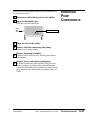
1
Inspect the coils.
Use a flashlight to check between coil surfaces.
2
3
Clean the dirty coils with a soft brush.
Flush with cool water or a commercial
coil cleaner.
If your unit has the optional air filter supplied by Conair, clean
it using water or air. Replace as needed.
5-8
MAINTENANCE
Series 1 Portable Chillers, TIC Control
UGH016/0500
WARNING: Electrical hazard
Before performing any work on this item, disconnect and lock out electrical power sources to
prevent injury from unexpected energization or
startup.
CHECKING
ELECTRICAL
CONNECTIONS
WARNING: Improper installation, operation, or servicing may result in
equipment damage or personal injury.
This equipment should only be installed, adjusted, and serviced by qualified technical personnel who are familiar with the construction, operation, and potential hazards of this type of
machine.
All wiring, disconnects, and fuses should be
installed by qualified electrical technicians in
accordance with electrical codes in your region.
1
Be sure the main power is disconnected
and the chiller is locked out. Always disconnect and lockout the main power source before opening the unit for
servicing.
2
3
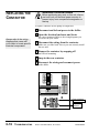
Open the electrical enclosure.
Inspect all wires and connections.
Look for loose wires, burned contacts, and signs of overheated wires. Compare the control wiring to the wiring
diagrams you received with your chiller. Have a qualified
electrician make any necessary repairs or replacements.
4
5
Always refer to the wiring
diagrams you received with
your chiller to locate specific electrical components.
Close the electrical enclosure door.
Inspect the exterior power cords.
Cords should not be crimped, exposed, or rubbing against
the frame. If the main power cord runs along the floor,
make sure it is not positioned where it could rest in pooling water or could be run over and cut by wheels or casters.
UGH016/0500
Series 1 Portable Chillers, TIC Control
MAINTENANCE
5-9
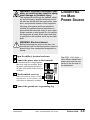
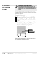
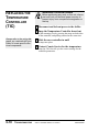
CHECKING
RESERVOIR
LEVEL
WARNING: Electrical hazard
Before performing any work on this item, disconnect and lock out electrical power sources to
prevent injury from unexpected energization or
startup.
Check the fluid level in the reservoir. The meniscus in the
sight glass on the back of the chiller should be in line with the
mark on the sight glass.
To manually fill the reservoir:
1
2
3
Disconnect and lockout power to the chiller.
Locate the fill port on the back of the chiller.
Refill the reservoir.
Monitor the level using the water level gauge on the back
of the chiller. Because the Portable Chiller can use either
pure water or a glycol solution, make sure your are
adding the correct fluid for your application.
Fill port
Fill/Drain valve
Water level gauge
If you have the optional make-up water level float switch, it
will automatically control the fluid level.
5-10
MAINTENANCE
Series 1 Portable Chillers, TIC Control
UGH016/0500
TROUBLESHOOTING
● Before Beginning . . . . . . . . . . . .6-2
● A Few Words of Caution . . . . . .6-2
● Identifying the Cause
of a Problem . . . . . . . . . . . . . .6-3
● Answering an Alarm . . . . . . . . .6-4
● Control Problems . . . . . . . . . . . .6-5
● Mechanical Conditions . . . . . . .6-6
● Checking and Replacing
Switches . . . . . . . . . . . . . . . .6-15
● Replacing the Contactor . . . . .6-16
● Checking and Replacing
the RTD . . . . . . . . . . . . . . . . .6-17
● Replacing the Temperature
Controller (TIC) . . . . . . . . . . .6-18
● Replacing Overload Modules .6-19
● Replacing Fuses . . . . . . . . . . .6-20
● Removing Pump
Components . . . . . . . . . . . . .6-21
● Checking the Pressure
Switches . . . . . . . . . . . . . . . .6-22
Series 1 Portable Chillers, TIC Control
UGH016/0500
6-1
BEFORE
BEGINNING
You can avoid most problems by following the recommended
installation, operation and maintenance procedures outlined in
this User Guide. If you have a problem, this section will help
you determine the cause and tell you how to fix it.
Before you begin troubleshooting:
❒ Find any wiring, piping, and assembly diagrams that
were shipped with your equipment. These are the best
reference for correcting a problem. The diagrams will
note any custom features or options not covered in this
User Guide.
❒ Verify that you have all instructional materials related
to the chiller. Additional details about troubleshooting
and repairing specific components are found in these
materials.
❒ Check that you have manual for other equipment connected in the system. Troubleshooting may require
investigating other equipment attached to, or connected
with the chiller.
A FEW WORDS
OF CAUTION
WARNING: Improper installation, operation, or servicing may result in equipment damage or personal injury.
This equipment should only be installed, adjusted, and serviced by qualified technical personnel who are familiar with the construction, operation, and potential hazards of this type of
machine.
All wiring, disconnects, and fuses should be
installed by qualified electrical technicians in
accordance with electrical codes in your region.
WARNING: Electrical hazard
Before performing any work on this item, disconnect and lock out electrical power sources to
prevent injury from unexpected energization or
startup.
WARNING: Refrigerant hazard
Only certified refrigerant technicians should
examine and correct problems involving the
refrigerant circuit.
6-2
TROUBLESHOOTING
Series 1 Portable Chillers, TIC Control
UGH016/0500
The Troubleshooting section covers problems directly related
to the operation and maintenance of the portable chiller. This
section does not provide solutions to problems that originate
with other equipment. Additional troubleshooting help can be
found in manual supplied with the other equipment.
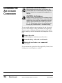
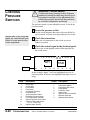
IDENTIFYING
THE CAUSE OF
A PROBLEM
Conditions you may see are:
● electrical - a fuse is out, a switch has tripped
● mechanical - pump, condenser not working
● physical - water flow incorrect
Always refer to the wiring
diagrams you received
with your chiller to locate
specific electrical components.
As part of troubleshooting you need to know the status of the
inputs and outputs. Open the electrical enclosure and check
the status of the inputs and outputs. When they are in normal
range, the numbers are highlighted. If the number is not highlighted, it is out of range.
I
Inputs
1 2
3
4
5
6
O
1
2
8
9 10 11 12
TIME
DAY
Outputs
7
3
4
5
6
7
8
In this example, inputs 7 and 8 are highlighted; they are in
normal position. The unhighlighted numbers are out of range.
Refer to the wiring diagram and the following table for the
switch status:
Input
1
2
3
4
5
6
7
8
9
10
11
12
Description
Output
Chiller Stop
Chiller Start
Level Switch
Flow Switch
Compressor Running
Pump Running
Suction Pressure Switch
Discharge Pressure Switch
Low Temperature Deviation
Optional Auto-Fill Level Switch
Pressure Differential Switch
(7.5, 10, 15 ton only)
Optional Alarm Silence
UGH016/0500
1
2
3
4
5
6
7
8
Description
Compressor Starter
Compressor Run Lamp
Pump Starter
Pump Run Lamp
Alarm Lamp
Optional Auto-Fill Solenoid
Optional Alarm Bell
Optional Alarm Strobe
Series 1 Portable Chillers, TIC Control
TROUBLESHOOTING
6-3
ANSWERING
ALARM
AN
When an alarm condition occurs, the alarm light on the control panel lights. It stays lit until the alarm condition is corrected. If you have the optional audible alarm, pressing the
Enter button silences the audible alarm.
To find out what is causing the alarm, check the indicator
lights on the control panel for the pump and compressor status. If the pump and compressor are both off, check the water
tank level, flow valves, and the pump. If the pump is on and
the compressor is off, check the compressor, suction pressure
and discharge pressure.
Alarm Condition
Description
Pump
Status
Compressor
Status
Low Water Tank Level
The water level in the pump tank is low.
OFF
OFF
Flow Fault
There is no flow of the process fluid at the
pump discharge.
OFF
OFF
Pump Overload
There is a high amperage condition; the
pump is drawing too much current.
OFF
OFF
Compressor Overload
There is a high amperage condition; the
compressor is drawing too much current.
ON
OFF
High Discharge Pressure
The refrigerant pressure, as measured at the
compressor outlet is high.
ON
OFF
Low Suction Pressure
The refrigerant pressure, as measured at the
inlet of the compressor is low.
ON
OFF
Refer to the Troubleshooting tables and the wiring diagrams to
correct the alarm condition.
6-4
TROUBLESHOOTING
Series 1 Portable Chillers, TIC Control
UGH016/0500
Look here if the control panel is not lit, or if the power is on
and the Portable Chiller will not run.
CONTROL
PROBLEMS
Symptom
Possible cause
Solution
The control is not lit
and the chiller is not
working.
Power is not reaching the
chiller.
❐ Check the power cord and
plug. Make sure the cord and
plug are properly connected.
❐ Make sure the main disconnect switch is on.
❐ Check fuses and breakers.
Replace or reset as required.
The correct power is not
reaching the unit
Check the voltage specification
on the chiller nameplate.
There is a problem with
the TIC control.
❐ Check fuses and replace as
needed.
❐ Check the power to the temperature controller. Reconnect
or replace as needed.
❐ Check the TIC indicator
lights and replace as needed.
There is a problem with
the control panel.
UGH016/0500
The control panel may have
failed. Contact Conair Service.
Series 1 Portable Chillers, TIC Control
TROUBLESHOOTING
6-5
CONTROL
PROBLEMS
CONT’D
6-6
Symptom
Possible cause
Solution
The control is lit and
there is no alarm
condition. The compressor hums, but
does not run.
The input voltage is
incorrect
Check the main supply voltage. It must be within 10% of
the nameplate rating.
There is a phase loss.
❐ Check the fuses on the main
power supply.
❐ Check the phase-to-phase
voltages.
❐ Check phase continuity
through the compressor contactor.
❐ Check the wiring at the
compressor.
Replace or repair as needed.
TROUBLESHOOTING
Series 1 Portable Chillers, TIC Control
UGH016/0500
Look here when the Alarm/Shutdown light on the control
panel is lit. See Answering an Alarm, in the Troubleshooting
section before going to these tables.
MECHANICAL
CONDITIONS
Solution
Alarm
Possible cause
Low Water Tank
Level (pump and
compressor are off)
Water level in tank is low. Fill tank to proper level. See
Checking Reservoir Level, in
the Maintenance section.
Inspect for leaks in the process
piping. Repair as necessary.
See Making Plumbing
Connections, in the Installation
section.
Failed Level switch.
UGH016/0500
Check level gauge and compare it to status of the level
switch by checking continuity
of switch in electrical enclosure. Refer to wiring diagrams.
Series 1 Portable Chillers, TIC Control
TROUBLESHOOTING
6-7
MECHANICAL
CONDITIONS
6-8
Alarm
Possible cause
Solution
Flow fault (pump
and compressor are
off)
The To Process and From
Process valves are closed.
Open valve(s).
The Process Fluid strainer is clogged.
Clean the strainer.
Water level in reservoir is
low.
Fill the reservoir. See Making
Process Plumbing
Connections, in the Installation
section.
The evaporator is fouled.
Clean Evaporator. See
Cleaning the Evaporator or
Water-cooled Condenser, in the
Maintenance section.
Pump is not running.
Check overload module.
Replace as needed. See
Replacing Overload Modules,
in the Troubleshooting section.
Pump is running backwards.
Switch any two of the three
main power leads to the pump.
TROUBLESHOOTING
Series 1 Portable Chillers, TIC Control
UGH016/0500
MECHANICAL
CONDITIONS
CONT’D
Alarm
Possible cause
Solution
Pump Overload
(pump and compressor are off)
Overload set incorrectly.
Check table on wiring diagram
for correct amperage. Adjust
overload accordingly.
Low supply voltage.
❏ Check supply voltage.
Supply voltage to contactor
should be +- 10% of nameplate voltage.
❏ Check wire terminations
and connections. Tighten if
loose.
Faulty contactor
Check line and load side of
contactor. It should be less
than 5 volt drop across the
contactor. If it is not, replace
the contactor. See Replacing
the Contactor in the
Troubleshooting section.
Faulty overload module.
Check amp draw of circuit. If
it is under the rated setting,
replace the overload module.
See Replacing Overload
Modules, in the
Troubleshooting section.
UGH016/0500
Series 1 Portable Chillers, TIC Control
TROUBLESHOOTING
6-9
MECHANICAL
CONDITIONS
CONT’D
6-10
Alarm
Possible cause
SOLUTION
Compressor
Overload (pump is
running and compressor is off)
Overload set incorrectly.
Check table on wiring diagram
for correct amperage. Adjust
overload accordingly.
Low supply voltage.
❏ Check supply voltage.
Supply voltage to contactor
should be +- 10% of nameplate voltage.
❏ Check wire terminations
and connections. Tighten if
loose.
Faulty contactor.
Check line and load side of
contactor. It should be less
than 5 volt drop across the
contactor. If it is not, replace
the contactor. See Replacing
the Contactor in the
Troubleshooting section.
Faulty overload module.
Check amp draw of circuit. If
it is under the rated setting,
replace the overload module.
See Replacing Overload
Modules, in the
Troubleshooting section.
TROUBLESHOOTING
Series 1 Portable Chillers, TIC Control
UGH016/0500
MECHANICAL
CONDITIONS
CONT’D
Alarm
Possible cause
Solution
High Discharge
Pressure (pump is
running, compressor
is off)
Clogged/dirty air-cooled
condenser.
Clean the coil. See Cleaning
the Air-cooled Condenser, in
the Maintenance section.
Blocked air flow to aircooled condenser.
Move chiller or unblock air
passageway.
Low condenser water
flow or water too warm
to water-cooled condenser.
Check required flow; see
Specifications in the
Description section.
Blocked condenser water
line or valve closed.
Unblock line; open valve.
Water-cooled condenser
fouled.
Clean the condenser. See
Cleaning the Air-cooled
Condenser, and Cleaning the
Evaporator or Water-cooled
Condenser, in the Maintenance
section.
UGH016/0500
Series 1 Portable Chillers, TIC Control
TROUBLESHOOTING
6-11
MECHANICAL
CONDITIONS
CONT’D
6-12
Alarm
Possible cause
Solution
High Discharge
Pressure, cont’d
Compressor discharge
valve closed.
Open valve.
Overcharged with refrigerant.
See Checking the Refrigerant
Charge in the Maintenance
section.
Faulty water regulating
valve.
Repair or replace the valve.
Faulty pressure switch.
See Checking the Pressure
Switches, in the
Troubleshooting section.
TROUBLESHOOTING
Series 1 Portable Chillers, TIC Control
UGH016/0500
MECHANICAL
CONDITIONS
CONT’D
Alarm
Possible cause
Solution
Low Suction
Pressure (pump is
running and compressor is off)
No or low flow with a
failed flow switch and
RTD.
❏ Check To Process and From
Process valves to see if they
are open.
❏ Check Flow switch and
RTD. Replace as needed.
Compressor suction valve
is closed.
Open valve.
No load on the Chiller.
Check process load for
required load. Chiller may be
oversized.
The Evaporator is fouled.
Clean Evaporator. See
Cleaning the Evaporator or
Water-cooled Condenser, in the
Maintenance section.
The Evaporator is frozen. ❏ Check RTD; Replace as
needed.
❏ Check minimum allowable
setpoint for percent glycol
used.
There is a refrigerant
leak.
The pressure switch is
faulty.
UGH016/0500
Check for oil in chiller cabinet
and bubbles in refrigerant site
glass. Consult Conair Service
for repair.
See Checking Pressure
Switches, in the
Troubleshooting section.
Series 1 Portable Chillers, TIC Control
TROUBLESHOOTING
6-13
MECHANICAL
CONDITIONS
CONT’D
6-14
Symptom
Possible cause
Solution
Compressor fault.
Leads are backwards.
Swap any two of the three
main power leads to the compressor.
The compressor failed.
Contact Conair Service.
TROUBLESHOOTING
Series 1 Portable Chillers, TIC Control
UGH016/0500
WARNING: Electrical hazard
Before performing any work on this unit, disconnect and lock out electrical power sources to
prevent injury from unexpected energization or
startup.
The pump tank has one or two float switches. The float switch
(low level cutout) activates an alarm. There is also a flow
switch in the process fluid line to verify flow.
CHECKING AND
REPLACING
SWITCHES
To replace a switch:
1
2
Disconnect and lockout power to the chiller.
Open the electrical enclosure and locate the
connection for the correct switch on the terminal switch.
Refer to the wiring diagrams you received with your
chiller to find the correct terminals.
3
Check the switch.
Check continuity within the switch and make sure it corresponds to the condition of the switch. Clean the switch
if needed.
4
Replace the switches as needed.
Drain the tank to replace the switch(es).
To check a flow switch:
1
2
Remove the electrical cover on the flow switch.
Slide the top of the switch housing over until
the N.O. (normally open) shows when electrical cover is
placed back on.
3
Always refer to the wiring
diagrams that came with
your chiller to locate specific
electrical components.
Replace electrical cover on flow switch.
Flow switch
Level switch
UGH016/0500
Series 1 Portable Chillers, TIC Control
TROUBLESHOOTING
6-15
WARNING: Electrical hazard
REPLACING THE
CONTACTOR
Before performing any work on this unit, disconnect and lock out electrical power sources to
prevent injury from unexpected energization or
startup.
To replace contactor for the pump or compressor:
1
2
Always refer th the wiring
diagrams that came with
your chiller to locate specific
electrical components.
Disconnect and lockout power to the chiller.
Open the electrical enclosure and locate
the correct contactor. Refer to the wiring diagrams you
received with your chiller.
3
Disconnect the wiring from the contactor.
Make sure you label each wire so you can correctly install
the new unit.
4
Remove the contactor by snapping off
the DIN rail mounting.
5
Snap in the new contactor.
6
Reconnect the wiring and reconnect power
to the chiller.
Pump contactor
Compressor
contactor
6-16
TROUBLESHOOTING
Series 1 Portable Chillers, TIC Control
UGH016/0500
The Conair Portable Chiller uses a standard 100 ohm RTD to
monitor process temperature. Disconnect the RTD leads and
measure the resistance through the RTD. It should read 95 110 ohms. If it does not, the RTD is bad and needs replaced.
To replace the RTD:
1
2
CHECKING AND
REPLACING THE
RTD
Disconnect and lockout power to the chiller.
Disconnect the To Process tubing from the
To Process connection.
Fill/Drain valve
To Process
connection
3
Open the Drain/Fill valve and drain water
from the unit so the water level is lower that the RTD.
4
5
Open the side of the chiller.
Always refer th the wiring
diagrams that came with
your chiller to locate specific
electrical components.
Disconnect the RTD wiring from the
temperature controller in the top electrical panel. Refer to
the wiring diagram.
6
Remove the RTD.
Loosen the compression nut to slide the RTD out of the
evaporator.
7
Install the new RTD.
The new RTD should be inserted in the evaporator so that
the tip is extended completely through the evaporator.
8
Wire the RTD to the controller
in the top electrical enclosure.
RTD
UGH016/0500
Series 1 Portable Chillers, TIC Control
TROUBLESHOOTING
6-17
REPLACING THE
TEMPERATURE
CONTROLLER
(TIC)
WARNING: Electrical hazard
Before performing any work on this unit, disconnect and lock out electrical power sources to
prevent injury from unexpected energization or
startup.
1
2
Disconnect and lockout power to the chiller.
Snap the Temperature Controller board out
of the mounting case by pressing the snaps on both sides
of the controller, and pulling outward at the same time.
Always refer to the wiring diagrams you received with your
chiller to locate specific electrical components.
3
Slide the new controller in until
it snaps into place.
4
Contact Conair Service for the temperature
setup list. This list tells you the correct settings for the
controller parameters.
6-18
TROUBLESHOOTING
Series 1 Portable Chillers, TIC Control
UGH016/0500
WARNING: Electrical hazard
Before performing any work on this unit, disconnect and lock out electrical power sources to
prevent injury from unexpected energization or
startup.
REPLACING
OVERLOAD
MODULES
Normally if the overload trips, resetting the overload and correcting the cause is typically all that is needed. However, if the
overload continues to trip, it may be necessary to replace the
overload module.
To replace the overload module:
1
2
3
Disconnect and lockout power to the chiller.
Open the electrical enclosure.
Always refer to the wiring diagrams you received with your
chiller to locate specific electrical components.
Locate the overload module and disconnect
the power leads from the module to the device. Refer to
the wiring diagram for the exact location. Note the placement of each lead and label as needed.
4
5
6
Disconnect auxiliary wiring to the module.
Loosen the screws and remove the module.
Install the new module
and tighten in place with the screws.
7
8
Reconnect wires and leads.
Adjust setting to correct Full Load Amps
rating of compressor, fan or pump.
9
Restore power to the chiller.
Pump overload
module
Compressor overload module
UGH016/0500
Series 1 Portable Chillers, TIC Control
TROUBLESHOOTING
6-19
REPLACING
FUSES
WARNING: Electrical hazard
Before performing any work on this unit, disconnect and lock out electrical power sources to
prevent injury from unexpected energization or
startup.
To replace fuses:
1
2
Disconnect and lockout power to the chiller.
Open the electrical enclosure and locate
the fuses. Refer to the wiring diagram for the exact location.
Always refer to the wiring diagrams you received with your
chiller to locate specific electrical components.
6-20
TROUBLESHOOTING
3
4
Remove and replace fuses.
Restore power to the chiller.
Control transformer
primary fuses
Control transformer
secondary fuse
Series 1 Portable Chillers, TIC Control
UGH016/0500
The pump’s wet end (impeller, motor, and seal assembly) can
be removed for service.
1
2
Disconnect and lockout power to the chiller.
Open the drain/fill valve.
REMOVING
PUMP
COMPONENTS
Drain the water from the chiller.
Open
this
side
3
4
Fill/Drain valve
Open the side of the chiller.
Remove the bolts connecting the pump
assembly to the pump housing.
5
6
Remove the pump assembly.
Carefully slide it sideways away from the pump tank to
avoid damage.
Inspect, clean, and replace pump parts
as needed. Separate the pump assembly form the pump
volute (casing) by prying the flanges and pulling apart.
Follow the disassembly and reassembly procedures in the
pump manufacturer’s manual that accompanies this User
Guide.
UGH016/0500
Series 1 Portable Chillers, TIC Control
TROUBLESHOOTING
6-21
CHECKING
PRESSURE
SWITCHES
WARNING: Coolant hazard
Coolant can cause freezing of skin. All proper
precautions should be taken any time the cooling system is worked on. Any adjustment that
involves the coolant should only be performed
by a certified refrigeration technician.
The pressure switch is a non-adjustable switch. To check the
pressure switch:
1
Locate the pressure switch.
Use the wiring diagrams that came with your chiller for
exact location. Location varies depending on size of unit.
Always refer to the wiring diagrams you received with your
chiller to locate specific electrical components.
2
Check the connections.
Make sure all connections to the switch are secure.
Tighten as needed.
3
Check the control signal in the electrical panel.
Refer to the wiring diagram and the following table for
the switch status:
Inputs
I
1 2
3
4
5
6
DAY
Outputs
O
1
2
3
7
8
9 10 11 12
TIME
4
5
6
7
8
In this example, inputs 7 and 8 are highlighted; they are in
normal position. If they are not highlighted the input is out of
range.
Input
1
2
3
4
5
6
7
8
9
10
11
12
6-22
Description
Chiller Stop
Chiller Start
Level Switch
Flow Switch
Compressor Running
Pump Running
Suction Pressure Switch
Discharge Pressure Switch
Low Temperature Deviation
Optional Auto-Fill Level Switch
Pressure Differential Switch
(7.5, 10, 15 ton only)
Optional Alarm Silence
TROUBLESHOOTING
Output
1
2
3
4
5
6
7
8
Series 1 Portable Chillers, TIC Control
Description
Compressor Starter
Compressor Run Lamp
Pump Starter
Pump Run Lamp
Alarm Lamp
Optional Auto-Fill Solenoid
Optional Alarm Bell
Optional Alarm Strobe
UGH016/0500
Item
Description
CHECKING
PRESSURE
SWITCHES
High Pressure Switches (PS-2)
Cut out @ 300 PSIG on rise
CONT’D
Low Pressure Switches (PS-1)
Cut out at 28 PSIG on fall
Cut in at 43 PSIG on rise
4
Check the continuity within the switch
and make sure it corresponds to the following conditions:
If required, check the switch with a refrigeration gauge. If
the switch does not change, as listed in this table, when
compared to a refrigeration pressure gauge, the switch is
faulty. Replace the switch.
UGH016/0500
Series 1 Portable Chillers, TIC Control
TROUBLESHOOTING
6-23
Conair has made the largest investment in customer support in
the plastics industry. Our service experts are available to help
with any problem you might have installing and operating
your equipment. Your Conair sales representative also can help
analyze the nature of your problem, assuring that it did not
result from misapplication or improper use.
WE’RE HERE
TO HELP
To contact Customer Service personnel, call:
HOW TO CONTACT
CUSTOMER
SERVICE
From outside the United States, call: 814-437-6861
You can commission Conair service personnel to provide onsite service by contacting the Customer Service Department.
Standard rates include an on-site hourly rate, with a one-day
minimum plus expenses.
If you do have a problem, please complete the
following checklist before calling Conair:
❒ Make sure you have all model, serial and parts list
numbers for your particular equipment. Service
personnel will need this information to assist you.
BEFORE YOU
CALL ...
❒ Make sure power is supplied to the equipment.
❒ Make sure that all connectors and wires within
and between control systems and related
components have been installed correctly.
❒ Check the troubleshooting guide of this manual
for a solution.
❒ Thoroughly examine the instruction manual(s)
for associated equipment, especially controls.
Each manual may have its own troubleshooting
guide to help you.
❒ Check that the equipment has been operated as
described in this manual.
❒ Check accompanying schematic drawings for
information on special considerations.
IMS0002/0296
SERVICE INFORMATION
Additional manuals and
prints for your Conair
equipment may be
ordered through the
Customer Service or
Parts Departments for
a nominal fee.
APPENDIX A-1
EQUIPMENT
GUARANTEE
Conair guarantees the machinery and equipment on this
order, for a period as defined in the quotation from date of
shipment, against defects in material and workmanship
under the normal use and service for which it was recommended (except for parts that are typically replaced after
normal usage, such as filters, liner plates, etc.). Conair’s
guarantee is limited to replacing, at our option, the part or
parts determined by us to be defective after examination.
The customer assumes the cost of transportation of the
part or parts to and from the factory.
PERFORMANCE
WARRANTY
Conair warrants that this equipment will perform at or
above the ratings stated in specific quotations covering the
equipment or as detailed in engineering specifications,
provided the equipment is applied, installed, operated and
maintained in the recommended manner as outlined in our
quotation or specifications.
Should performance not meet warranted levels, Conair at
its discretion will exercise one of the following options:
● Inspect the equipment and perform alterations or
adjustments to satisfy performance claims. (Charges
for such inspections and corrections will be waived
unless failure to meet warranty is due to misapplication, improper installation, poor maintenance practices
or improper operation.)
● Replace the original equipment with other Conair
equipment that will meet original performance claims
at no extra cost to the customer.
● Refund the invoiced cost to the customer. Credit is
subject to prior notice by the customer at which time a
Return Goods Authorization Number (RGA) will be
issued by Conair’s Service Department. Returned
equipment must be well crated and in proper operating
condition, including all parts. Returns must be prepaid.
Purchaser must notify Conair in writing of any claim and
provide a customer receipt and other evidence that a claim
is being made.
WARRANTY
LIMITATIONS
A-2
SERVICE INFORMATION
Except for the Equipment Guarantee and Performance
Warranty stated above, Conair disclaims all other warranties with respect to the equipment, express or
implied, arising by operation of law, course of dealing,
usage of trade or otherwise, including but not limited to
the implied warranties of merchantability and fitness for
a particular purpose.
WARRANTY INFORMATION
IMS0003/0796
MAINTENANCE
LOG
Date
Reading
Maintenance Item
Compressor Amps,
100% loaded
Discharge Pressure
Suction pressure
Evaporator water out
temperature
Process Water Pressure,
In/Out
Condenser Water
Temperature, In/Out
Condenser Water
Pressure, In/Out
Condenser Fan Amps (1)
Condenser Fan Amps (2)
Pump Amps
UGH016/0500
Series 1 Portable Chillers, TIC Control
APPENDIX B-1
Evaporator and Piping
Pressure Drops
Pressure Drop, PSID
A1/W1-2
A1/W1-1.5
PRESSURE
TABLES
A1/W1-3
A1/W1-7.5
A1/W1-10, A1-13
A1/W1-4
A1/W1-5
W1-15
Flow Rate, GPM
UGH016/0500
Series 1 Portable Chillers, TIC Control
APPENDIX C-1
Condenser and Piping
Pressure Drops
PRESSURE
TABLES
80
W1-1.5
W1-2
Pressure Drop, PSID
70
W1-3
W1-7.5
W1-4
60
W1-5
W1-10
W1-15
50
40
30
20
10
0
0
5
10
15
20
25
30
35
40
45
50
55
Flow Rate, GPM
APPENDIX C-2
Series 1 Portable Chillers, TIC Control
UGH016/0500
CONTROL
SETTINGS
Use this table when configuring the temperature controller.
Refer to the manufacturer’s manual that accompanies this
User Guide for detailed information.
When the control displays the text listed in the Display column, you can scroll to, and change, the settings listed in the
Parameter column.
Display
Parameter Description
Setting
Units
InP
SP.LL
SP.HL
TyPE
Lower Setpoint limit
Upper Setpoint Limit
Input sensor type
40
70
rtd
°F
°F
100 ohm rtd
DSPL
dspl
Unit
Display menu
Temperature units
---F
----°F or °C
OutP
O1.ty
O1.ac
O1.cy
O1.hl
O2.ty
O2.aa
O2.ao
O2.ih
O2.SP
Output
Output
Output
Output
Output
Output
Output
Output
Output
PID
re
5
80%
ALr
nor
DE.L
En
4
----Reverse action
Seconds
% time HGV is on
--------Alarm set to low deviation
Enabled
°F Low deviation
Cnrl
Pb1
der
OFFS
Int
Proportional Band-gain
Derivative Action - rate
Manual reset
Integral Action - reset
1
0
OFF
0
-----------------
UGH016/0601
1 Type
1 action
1 cycle type
1 High limit
2 Control Type
2 Alarm 1 Action
2 process
2 alarm inhibit
2 alarm setpoint
Series 1 Portable Chillers, TIC Control
APPENDIX
D-1
PARTS & DIAGRAMS
● Spare Parts Lists . . . . . . . . . .P/D-2
UGH016/0500
Series 1 Portable Chillers, TIC Control
P/D-1
RECOMMENDED
SPARE PARTS
Part
Number
Description
Athena 1/32 DIN Temperature Controller
120VAC LOGO! Long
120VAC 4” Alarm Bell
20VAC White Strobe
22 mm Red extended pushbutton operator
22 mm Green flush pushbutton operator
120VAC Green Indicator light
120VAC Red indicator light
MSP-to-Contactor connecting module, 3RA1921-1A
MSP-to-Contactor connecting module, 3RA1921-1B
MSP-to-Contactor
MSP-to-Contactor
MSP-to-Contactor
MSP-to-Contactor
MSP-to-Contactor
P/D-2
SPARE PARTS
connecting
connecting
connecting
connecting
connecting
module,
module,
module,
module,
module,
3RA1921-1D
3RA1931-1A
3RA1931-1B
3RA1941-1A
3RA1941-1B
3
3
3
3
3
Pole
Pole
Pole
Pole
Pole
Contactor
Contactor
Contactor
Contactor
Contactor
w/
w/
w/
w/
w/
120VAC
120VAC
120VAC
120VAC
120VAC
coil, 7A (AC-3)
coil, 9A (AC-3)
coil 12A (AC-3)
coil, 17A (AC-3)
coil, 25A (AC-3)
3
3
3
3
3
Pole
Pole
Pole
Pole
Pole
Contactor
Contactor
Contactor
Contactor
Contactor
w/
w/
w/
w/
w/
120VAC
120VAC
120VAC
120VAC
120VAC
coil,
coil,
coil,
coil,
coil,
28A
32A
40A
50A
65A
Motor
Motor
Motor
Motor
Motor
Starter
Starter
Starter
Starter
Starter
Protector
Protector
Protector
Protector
Protector
(1.8-2.5A)
(2.2-3.2A)
(3.5-5.0A)
(4.5-6.3A)
(5.5-8.0A)
Motor
Motor
Motor
Motor
Motor
Starter
Starter
Starter
Starter
Starter
Protector
Protector
Protector
Protector
Protector
(7.0-10.0A)
(9.0-12.5A)
(11.0-16.0A)
(14.0-20.0A)
(17.0-22.0A)
Series 1 Portable Chillers, TIC Control
(AC-3)
(AC-3)
(AC-3)
(AC-3)
(AC-3)
UGH016/0500
RECOMMENDED
SPARE PARTS
Part
Number
Description
Motor
Motor
Motor
Motor
Motor
Starter
Starter
Starter
Starter
Starter
Protector
Protector
Protector
Protector
Protector
(20.0-25.0A)
(18.0-25.0A)
(22.0-32.0A)
(28.0-40.0A)
(40.0-50.0A)
Motor Starter Protector (45.0-63.0A)
Motor Starter Protector (57.0-75.0A)
MSP Auxiliary Contact Block (2 N.O.)
MSP Line Side Feeder
MSP Feeder Lug (3RV101, 3RV102)
MSP Feeder Lug (3RV103)
Normally Open contact block
Normally Closed contact block
Control Terminal Block, Size 4
Terminal Block End Bracket
Terminal Block Barrier
Littlefuse 0.5A Fuse, 250VAC
Littlefuse 3.0A Fuse, 250VAC
Littlefuse 5.0A Fuse, 250VAC
Littlefuse 0.25A Fuse, 600VAC
Littlefuse 2.0A Fuse, 600VAC
1 Pole Fuseblock Cover Lit
Transformer Touch Safe Cover Lit
1 Pole Secondary Fuseblock
2 Pole Primary Fuseblock
Littlefuse 2 Pole Ultrasafe Fuseblock
Motorola 5 VDC Voltage Regulator
250VA Control Transformer 230x460, 110/115/120
250VA Control Transformer 550/575/600, 110/115/120
250VA Control Transformer 380/400/415, 110x120
250VA Control Transformer 208/230/460, 24/115
Pump Seal Kit, pump type 231
Pump Seal Kit, Pump type 233, 3HP
Pump Seal Kit, Pump type 233, 5HP
Pump Seal Kit, Pump type 234, 7.5HP
UGH016/0500
Series 1 Portable Chillers, TIC Control
SPARE PARTS
P/D-3
RECOMMENDED
SPARE PARTS
Part
Number
20973003
26636101
26629901
26638902
26638901
26638903
2663890
20966802
331021051
2920580201
2920581001
2920581301
2920580202
2920581302
2920940902
2920941302
2920941802
29213103
29213104
P/D-4
SPARE PARTS
Description
Pump Seal Kit, Pump type 233, 7.5HP and 10HP
Pump Seal Kit, Pump type 234, 10HP and 15HP
Flowtect, Flow Switch, Evap Circuit
Gems, Float Switch, Process Tank
Pressure Gauge, Dual Scale, 0-160PSIG
Discharge pressure switch, cut out at 300 PSIG on
rise, cut in at 275 PSIG on fall, 1/4” with Schreader
depressor
Suction pressure cut out at 28 PSIG on fall, cut in at
43 PSIG on rise, 1/4” with Schreader depressor
Fan Cycling Switch #1, Air-cooled Chiller, cut out at
190 PSIG on fall, Cut in at 250 PSIG on rise, 1/4”
with Schreader depressor
Fan Cycling Switch #2, Air-cooled Chiller, cut out at
200 PSIG on fall, Cut in at 270 PSIG on rise, 1/4
with Schreader depressor
8”x14’ 100ohm RTD
Differential Pressure Switch, 0-45 PSID
Refrigerant Pressure Relief Valve, 400PSIG, Aircooled Chiller (1-4 ton)
Refrigerant Pressure Relief Valve, 400PSIG, Aircooled Chiller (5-7.5 ton)
Refrigerant Pressure Relief Valve, 400PSIG, Aircooled Chiller (10 and 13 ton)
Refrigerant Pressure Relief Valve, 350PSIG, Watercooled Chiller (1.5-5 ton)
Refrigerant Pressure Relief Valve, 350PSIG, Watercooled Chiller (7.5-15 ton)
Filter Dryer, 1.5-3 ton
Filter Dryer, 4-7.5 ton
Filter Dryer, 10-15 ton
TXV 1.5 ton Water-cooled
TXV 1.5 ton Air-cooled, 2 ton Water- and Air-cooled
Series 1 Portable Chillers, TIC Control
UGH016/0500
RECOMMENDED
SPARE PARTS
Part
Number
Description
29213105
29213106
29213107
29213108
29213109
TXV
TXV
TXV
TXV
TXV
2 ton Water- and Air-cooled
3 ton Water- and Air-cooled
5 ton Water- and Air-cooled
7.5 ton Water- and Air-cooled
10 ton Water- and Air-cooled
292131110
20958401
20958402
20958403
20958404
TXV 13 ton Water-cooled and 15 ton Air-cooled
Liquid Line Solenoid Valve, 1-5 ton
Liquid Line Solenoid Valve, 7.5-10 ton
Liquid Line Solenoid Valve, 13-15 ton
Hot Gas Bypass Solenoid, 1.5-4 ton
20958405
20958406
3331302204
3331302202
3331302201
Hot Gas Bypass Solenoid, 5-10 ton
Hot Gas Bypass Solenoid, 13 and 15 ton
Air Filter, 1.5 ton Air-cooled
Air Filter, 2 and 3 ton Air-cooled
Air Filter, 4 and 5 ton Air-cooled
3331302203 Air Filter, 7.5-10 ton Air-cooled
3331302
Air Filter, 13 ton Air-cooled
Condenser Fan Motor, 50 watts, 400/460V, 50/60Hz, for
A1-2.25 unit
Condenser Fan Motor, 0.166HP, 400/460V, 50/60Hz, for
A1-1.5 and A1-3 units
Condenser Fan Motor, 1/4HP, 400/460V, 50/60Hz, for
A1-4 and A1-5 units
Condenser Fan Motor, 1/2HP, 400/460V, 50/60Hz, for
A1-7.5, A1-10 and A1-13 units
Condenser Fan Motor, 50 watts, 200/230V, 50/60Hz, for
A1-2.25 unit
Condenser Fan Motor, 0.166HP, 200/230V, and 575V,
50/60Hz, for A1-1.5 and A1-3 units
Condenser Fan Motor, 1/4HP, 200/230V, 50/60Hz, for
A1-4 and A1-5 units, and 575V, for A1-4 unit
Condenser Fan Motor, 1/2HP, 200/230V, 50/60Hz, for
A1-7.5, A1-10 and A1-13 units
UGH016/0500
Series 1 Portable Chillers, TIC Control
SPARE PARTS
P/D-5
RECOMMENDED
SPARE PARTS
Part
Number
Description
Condenser Fan Motor, 1/4HP, 575V, 60 Hz for A1-5 unit
Condenser Fan Motor, 1/2HP, 575V, 60Hz, for A1-7.5,
A1-10 and A1-13 units
Condenser Fan Blade, A1-1.5
Condenser Fan Blade, A1-2.25
26642001
26642002
26642102
P/D-6
SPARE PARTS
Condenser Fan Blade, A1-3.25
Condenser Fan Blade, A1-4 and A1-5
Condenser Fan Blade, A1-7.5, A1-10, A1-13
Water Regulating Valve, W1-1.5, W1-2, W1-3
Water Regulating Valve, W1-4, W1-5
Water Regulating 1 1/4” Control Ball Valve, W1-7.5, W110, W1-15 units
Series 1 Portable Chillers, TIC Control
UGH016/0500