1
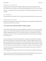
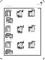
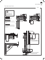
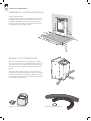
811142 BAV GB-7
March 2014
USER MANUAL FOR STOVES WITHOUT BOILERS
SUPPLEMENTARY INSTALLATION INSTRUCTIONS FOR THE UK MARKET
TO BE READ IN CONJUNCTION WITH THOSE IN THE INSTRUCTION BOOKLET
READ THE INSTRUCTION BOOKLET AND THESE SUPPLEMENTARY INSTRUCTIONS CAREFULLY BEFORE INSTALLATION
These instructions together with those in the instruction booklet cover the basic principles to ensure the
satisfactory installation of the stove, although detail may need slight modification to suit particular local site
conditions.
In all cases the installation must comply with current Building Regulations, Local Authority Byelaws and other
specifications or regulations as they affect the installation of the stove.
It should be noted that the Building Regulations requirements may be met by adopting the relevant recommendations given in British Standards BS 8303, BS EN 15287-1:2007 as an alternative means to achieve an
equivalent level of performance to that obtained following the guidance given in Approved Document J.
Should any conflict apply between these instructions and the original manufacturers instructions then the
most stringent advice must apply.
Please note that it is a legal requirement under England and Wales Building Regulations that the installation
of the stove is either carried out under Local Authority Building Control approval or is installed by a Competent
Person registered with a Government approved Competent Persons Scheme. HETAS Ltd operate such a Scheme
and a listing of their Registered Competent Persons can be found on their website at www.hetas.co.uk.
CO Alarms:Building regulations require that when ever a new or replacement fixed solid fuel or wood/biomass appliance is
installed in a dwelling a carbon monoxide alarm must be fitted in the same room as the appliance. Further guidance on the installation of the carbon monoxide alarm is available in BS EN 50292:2002 and from the alarm
manufacturer’s instructions. Provision of an alarm must not be considered a substitute for either installing
the appliance correctly or ensuring regular servicing and maintenance of the appliance and chimney system.
811142 BAV GB-7
March 2014
HEALTH AND SAFETY PRECAUTIONS
Special care must be taken when installing the stove such that the requirements of the Health and Safety at Work
Act are met.
Handling
Adequate facilities must be available for loading, unloading and site handling.
Fire Cement
Some types of fire cement are caustic and should not be allowed to come into contact with the skin. In case of
contact wash immediately with plenty of water.
Asbestos
This stove contains no asbestos. If there is a possibility of disturbing any asbestos in the course of installation then
please seek specialist guidance and use appropriate protective equipment.
Metal Parts
When installing or servicing this stove care should be taken to avoid the possibility of personal injury.
STOVE PERFORMANCE
Refer to the manufacturer’s main instruction manual for details of the stove’s performance.
PREPARATORY WORK AND SAFETY CHECKS
IMPORTANT WARNING
This stove must not be installed into a chimney that serves any other heating appliance.
There must not be an extractor fan fitted in the same room as the stove as this can cause the stove to emit fumes
into the room.
811142 BAV GB-7
March 2014
Chimney
In order for the stove to perform satisfactorily the chimney height must be sufficient to ensure an adequate
draught of approximately 15 Pa so as to clear the products of combustion and prevent smoke problems into the
room.
NOTE: A chimney height of not less than 4.5 metres measured vertically from the outlet of the stove to the top of
the chimney should be satisfactory. Alternatively the calculation procedure given in EN 13384-1 may be used as the
basis for deciding whether a particular chimney design will provide sufficient draught. BS EN 15287-1:2007 gives
additional details.
The outlet from the chimney should be above the roof of the building in accordance with the provisions of Building
Regulations Approved Document J.
If installation is into an existing chimney then it must be sound and have no cracks or other faults which might allow
fumes into the house. Older properties, especially, may have chimney faults or the cross section may be too large
i.e. more than 230 mm x 230 mm. Remedial action should be taken, if required, seeking expert advice, if necessary.
If it is found necessary to line the chimney then a flue liner suitable for solid fuel must be used in accordance with
Building Regulations Approved Document J.
Any existing chimney must be clear of obstruction and have been swept clean immediately before installation of the
stove. If the stove is fitted in place of an open fire then the chimney should be swept one month after installation to
clear any soot falls which may have occurred due to the difference in combustion between the stove and the open
fire.
If there is no existing chimney then any new system must be to the designation described above and in accordance
with Building Regulations Approved Document J.
A single wall metal fluepipe is suitable for connecting the stove to the chimney but is not suitable for use as the complete chimney. The chimney and connecting fluepipe must have a minimum diameter of 150 mm and its dimension
should be not less than the size of the outlet socket of the stove.
Any bend in the chimney or connecting fluepipe should not exceed 45°. 90° bends should not be used.
811142 BAV GB-7
March 2014
Combustible material should not be located where the heat dissipating through the walls of fireplaces or flues could
ignite it. Therefore when installing the stove in the presence of combustible materials due account must be taken of
the guidance on the separation of combustible material given in Building Regulations Approved Document J and also
in these stove instructions.
If it is found that there is excessive draught in the chimney then a draught stabiliser should be fitted. Fitting of a
draught stabiliser will affect the requirement for the permanent air supply into the room in which the stove is fitted
in accordance with Approved Document J (see also combustion air supply).
Adequate provision e.g. easily accessible soot door or doors must be provided for sweeping the chimney and connecting fluepipe where it is not intended for the chimney to be swept through the appliance.
Hearth
The hearth should be level and able to accommodate the weight of the stove and its chimney if the chimney is not
independently supported. The weight of the stove is indicated in the brochure.
The stove should preferably be installed on a non-combustible hearth of a size and construction that is in accordance with the provisions of the current Building Regulations Approved Document J.
The clearance distances to combustible material beneath, surrounding or upon the hearth and walls adjacent to the
hearth should comply with the guidance on the separation of combustible material given in Building Regulations
Approved Document J and also in these stove instructions.
If the stove is to be installed on a combustible floor surface, it must be covered with a non-combustible material at
least 12mm thick, in accordance with Building Regulations Approved Document J, to a distance of 30 cm in front of
the stove and 15 cm to each side measuring from the door of the combustion chamber.
811142 BAV GB-7
March 2014
Combustion air supply
In order for the stove to perform efficiently and safely there must be an adequate air supply into the room in which
the stove is installed to provide combustion air. The provision of air supply to the stove must be in accordance with
current Building Regulations Approved Document J. Special attention should be taken in newer build properties
where the design air permeability is less than 5m3/h.m2. Approved Document J gives more information on this. An
opening window is not appropriate for this purpose.
The fitting of an external air kit direct to outside air must not be considered substitute for installing the appliance with a permanently open air vent in compliance with ventilation requirements stated in Approved Document
J. Please reference ADJ for further guidance.
Connection to chimney
Stoves may have a choice of either a rear or top flue gas connector that allows connection to either a masonry chimney or a prefabricated factory made insulated metal chimney in accordance with their instructions. In some cases
it may be necessary to fit an adaptor to increase the diameter of the flue to the minimum required 150 mm section
of the chimney or liner. All joints in the connection between the stove and the chimney must be made gastight using
fire cement and where necessary fire-proof rope infill. Means should be made for sweeping the entire length of the
flue, be that through the appliance or by suitable sweeping hatch in the flue.
Commissioning and handover
Ensure all parts are fitted in accordance with the instructions.
On completion of the installation allow a suitable period of time for any fire cement and mortar to dry out, before
lighting the stove. Once the stove is under fire check all seals for soundness and check that the flue is functioning
correctly and that all products of combustion are vented safely to atmosphere via the chimney terminal.
On completion of the installation and commissioning ensure that the operating instructions for the stove are left
with the customer. Ensure to advise the customer on the correct use of the appliance and warn them to use only the
recommended fuel for the stove.
Advise the user what to do should smoke or fumes be emitted from the stove. The customer should be warned to use
a fireguard to BS 8423:2002 (Replaces BS 6539) in the presence of children, aged and/or infirm persons.
811142 BAV GB-7
March 2014
HETAS Ltd Approval;
These appliances have been approved by HETAS Ltd as an intermittent operating appliance for burning wood logs
only.
WARNING NOTE
Properly installed, operated and maintained this stove will not emit fumes into the dwelling. Occasional fumes from
de ashing and re fuelling may occur. However, persistent fume emission is potentially dangerous and must not be
tolerated. If fume emission does persist, then the following immediate action should be taken:
(a)
Open doors and windows to ventilate the room and then leave the premises.
(b)
Let the fire go out.
(c)
Check for flue or chimney blockage and clean if required
(d)
Do not attempt to relight the fire until the cause of the fume emission has been identified and corrected. If necessary seek expert advice.
The most common cause of fume emission is flueway or chimney blockage. For your own safety these must be kept
clean at all times.
IMPORTANT NOTES
General
Before lighting the stove check with the installer that the installation work and commissioning checks described
above have been carried out correctly and that the chimney has been swept clean, is sound and free from any
obstructions. As part of the stoves’ commissioning and handover the installer should have shown you how to operate
the stove correctly.
811142 BAV GB-7
March 2014
CO Alarm
Your installer should have fitted a CO alarm in the same room as the appliance. If the alarm sounds unexpectedly,
follow the instructions given under “Warning Note” above.
Air Controls
Manually operated air control can be managed by adjusting the air control valve to increase/decrease the air flow to
the stove.
Use of fireguard
When using the stove in situations where children, aged and/or infirm persons are present a fireguard must be
used to prevent accidental contact with the stove. The fireguard should be manufactured in accordance with BS
8423:2002.
Chimney cleaning
The chimney should be swept at least twice a year. It is important that the flue connection and chimney are swept
prior to lighting up after a prolonged shutdown period.
If the stove is fitted in place of an open fire then the chimney will require sweeping after a month of continuous
operation. This is a precaution to ensure that any “softer” deposits left from the open fire usage have not been
loosened by the higher flue temperatures generated by the closed stove.
In situations where it is not possible to sweep through the stove the installer will have provided alternative means,
such as a soot door. After sweeping the chimney the stove flue outlet and the flue pipe connecting the stove to the
chimney must be cleaned with a flue brush.
Periods of Prolonged Non-Use
If the stove is to be left unused for a prolonged period of time then it should be given a thorough clean to remove
ash and unburned fuel residues. To enable a good flow of air through the appliance to reduce condensation and
subsequent damage, leave the air controls fully open.
Extractor fan
There must not be an extractor fan fitted in the same room as the stove as this can cause the stove to emit smoke
and fumes into the room.
811142 BAV GB-7
March 2014
Aerosol sprays
Do not use an aerosol spray on or near the stove when it is alight.
Use of operating tools
Always use the operating tools provided when handling parts likely to be hot when the stove is in use.
Chimney Fires
If the chimney is thoroughly and regularly swept, chimney fires should not occur. However, if a chimney fire does occur turn off the stove immediately and isolate the mains electricity supply (if applicable), and tightly close the doors
of the stove. This should cause the chimney fire to go out. If the chimney fire does not go out when the above action
is taken then the fire brigade should be called immediately. Do not relight the stove until the chimney and flueway
have been cleaned and examined by a professional.
Permanent air vent
The stove requires a permanent and adequate air supply in order for it to operate safely and efficiently.
In accordance with current Building Regulations the installer may have fitted a permanent air supply vent into the
room in which the stove is installed to provide combustion air. This air vent should not under any circumstances be
shut off or sealed.
USER OPERATING INSTRUCTIONS
Please read the important notices given above before referring to the main instruction book for detailed operating
instructions.
Recommended fuels:
Please note that HETAS Ltd Appliance Approval only covers the use of wood logs on this appliance. HETAS Ltd Approval does not cover the use of other fuels either alone or mixed with the recommended fuels listed above, nor does it
cover instructions for the use of other fuels. The stoves have a refuelling interval of 0.75h to achieve the nominal
rated output. Wood logs should be seasoned with a moisture content of around 20%.
811142 BAV GB-7
March 2014
Refuelling on to a low fire bed:
If there is insufficient burning material in the firebed to light a new fuel charge, excessive smoke emission can
occur. Refuelling must be carried out onto a sufficient quantity of glowing embers and ash that the new fuel charge
will ignite in a reasonable period. If there are too few embers in the fire bed, add suitable kindling to prevent excessive smoke.
Fuel overloading:
The maximum amount of fuel specified in this manual should not be exceeded, overloading can cause excess smoke.
Operation with door left open:
Operation with the door open can cause excess smoke. The appliance must not be operated with the appliance door
left open except as directed in the instructions.
THE CLEAN AIR ACT 1993 AND SMOKE CONTROL AREAS
Under the Clean Air Act local authorities may declare the whole or part of the district of the authority to be a smoke
control area. It is an offence to emit smoke from a chimney of a building, from a furnace or from any fixed boiler if
located in a designated smoke control area. It is also an offence to acquire an ”unauthorised fuel” for use within a
smoke control area unless it is used in an ”exempt” appliance (”exempted” from the controls which generally apply in
the smoke control area).
The Secretary of State for Environment, Food and Rural Affairs has powers under the Act to authorise smokeless
fuels or exempt appliances for use in smoke control areas in England. In Scotland and Wales this power rests with
Ministers in the devolved administrations for those countries. Separate legislation, the Clean Air (Northern Ireland)
Order 1981, applies in Northern Ireland. Therefore it is a requirement that fuels burnt or obtained for use in smoke
control areas have been ”authorised” in Regulations and that appliances used to burn solid fuel in those areas (other
than ”authorised” fuels) have been exempted by an Order made and signed by the Secretary of State or Minister in
the devolved administrations.
Further information on the requirements of the Clean Air Act can be found here : http://smokecontrol.defra.gov.uk/
Your local authority is responsible for implementing the Clean Air Act 1993 including designation and supervision of
smoke control areas and you can contact them for details of Clean Air Act requirements
811142 BAV GB-7
March 2014
Appliance Exemption:
The Contura 500, 700, i4, i5, i30 and i40 series are recommended as exempt appliances under the Clean Air Act
1993 when burning dry seasoned wood logs in accordance with the instructions and when fitted with the permanent
stops detailed below:
The Contura 500 series must be fitted with a mechanical stop to prevent closure of the air control vent beyond the
20% open position when sold into smoke control areas.
The Contura 700 series must be fitted with a mechanical stop to prevent closure of the air control vent beyond the
28% open position when sold into smoke control areas.
The Contura i4 series must be fitted with a mechanical stop to prevent closure of the air control vent beyond the
30% open position when sold into smoke control areas.
The Contura i5 series must be fitted with a mechanical stop to prevent closure of the air control vent beyond the
30% open position when sold into smoke control areas.
The Contura i30 and i40 series must be fitted with a mechanical stop to prevent closure of the air control vent
beyond the 27% open position when sold into smoke control areas.
811142 BAV GB -7
2014-03-03
NIBE AB · Box 134 · 285 23 Markaryd · Sweden
www.contura.eu
Installation
Instructions
For use in GB and IE only
C i4
www.contura.eu
GB
82
CERTIFICATE
DECLARATION OF PERFORMANCE
No. Ci4-CPR-130619-SE-1
PRODUCT
Product type
Type designation
Manufacturing number
Intended area of use
Fuel
MANUFACTURER
Name
Address
CHECKS
According to AVCP
European standard
Test institute
Insert lit with solid biofuels
Contura i4
See rating plate on the insert
Heating of rooms in residential buildings
Wood / (Coal briquettes)
NIBE AB / Contura
Box 134, Skulptörvägen 10
SE-285 23 Markaryd, Sweden
System 3
EN 13229:2001 / A2:2004
Rein-Ruhr Feuerstätten Prüfstelle, NB 1625,
has checked declared performance and issued test report no. RRF-29 11 2751
DECLARED PERFORMANCE
Essential characteristics
Performance
Harmonised technical
specification
Reaction to fire
A1 WT
Minimum distance to combustible material
150 mm to rear
150 mm to side
According to the given conditions in the installation instructions
Risk of falling embers
Approved
Emissions from combustion
Wood / (Coal briquettes)
CO
NOx
OGC
PM
0.10% /
(0.21%)
108 mg/m3 / (NPD)
107 mg/m3 / (NPD)
36 mg/m3 / (10 mg/m3 )
Surface temperatures
Approved
Cleaning options
Approved
Mechanical durability
Approved
Emissions of hazardous substances
Approved
Nominal output
4 kW
/
(4 kW)
Efficiency
78%
/
(76%)
Flue gas temperature in connector at nominal
output
310°C
/
(270°C)
The undersigned is responsible for the manufacture and conformity with the declared performance.
Niklas Gunnarsson, Business area manager NIBE STOVES
Markaryd, 1st July 2013
EN 13229:2001 / A2:2004
GB
CONTENTS
A warm welcome to Contura.
A warm welcome to the Contura family. We hope
you will get a great deal of pleasure from your new
stove. As a new owner of a Contura stove you have
secured a product with timeless design and long
service life. Contura also has combustion that is both
environmentally friendly and efficient for the best heat
production.
Read through these installation instructions carefully
before installation. Read how to best light your stove in
the lighting instructions.
Table of contents
Technical data
84
Dimensions85
Recessing the insert
86
Recess example
87
Installation in Builders opening
88
Supply of combustion air
88
Prior to installation
89
Installing and connecting the convection box
90
Smoke control area
93
Installing stove body into the convection box
94
Installing fire box insulation panels
96
NOTE!
WARNING!
Report the installation of a stove to
your local authority.
The stove becomes very hot.
The owner of the house is personally responsible
for ensuring compliance with the mandatory safety
requirements and must have the installation approved by
a qualified inspector. Your local chimney sweep must also
be informed about the installation as this will affect the
routines for regular chimney-sweeping services.
During operation, certain surfaces of the stove become
very hot and can cause burn injury if touched. Be aware
of the strong heat radiated through the hatch glass.
Placing flammable material closer than the safe distance
indicated may cause a fire. Smouldering can cause quick
gas ignition with the risk of damage to property and
personal injury.
83
GB
84
FACTS
Technical data
Output
3-5 kW
Nominal output 4 kW
Efficiency level Up to 78%
ModelClassic
Weight (kg)
77
Width (mm)
490
Depth (mm)
420
Height (mm)
600
Model
Weight (kg)
Width (mm)
Depth (mm)
Height (mm)
Modern-3-sided frame
71
490
380
590
Model
Weight (kg)
Width (mm)
Depth (mm)
Height (mm)
Modern-4-sided frame
72
490
380
635
The connector’s inner diameter is Ø126 mm
Type approved in accordance with:
European standard EN-13 229
(DE/A) DINplus, Art. 15a B-VG
RRF-29 11 2751
DEFRA exempted
The stove can be used in Smoke Control
Areas.
General
Chimney
In this manual you will find instructions
about how your Contura i4 shall be
installed. Before you start the installation
it is important that you read this
instruction carefully and fully understand
the requirements. All European, national
and local standards and regulations needs
to be fulfilled when the appliance are
installed.
To guarantee the function and safety of
the stove we recommend that it is installed
by a professional. Our Contura agents can
recommend a suitable installer.
Note! The stove installation and connection
to a chimney must be accomplished with
the current edition of Building Regulations.
We recommend that you consult a local
chimney sweep before the installation
to make sure that the chimney is in good
condition.
The stove is type approved and must be
connected to a chimney dimensioned
for at least 350°C. The connector on
the appliance is suitable for pipes with
diameter of 125 mm.
The room or space containing a stove shall
have a permanent air supply sufficent to
ensure proper combustion, to determine
correct amount of air supply use current
edition of Building Regulations.
Remember to use only for the appliance
recommended fuel as wood logs
or smokeless fuel as anthracite or
manufactured smokeless fuel briquettes.
Do not ever burn bituminous coal, “petrocoke” or other petroleum based fuels!
Building application
Before installing a stove or erecting a
chimney it is necessary for you to apply
for planning permission from your local
authority. Ask your local authority for
advice regarding building regulations and
the application.
A flexible flue liner or steel flue
certified for use with solid fuel is highly
recommended. The stove requires a
draught in the chimney of at least –12
Pa. The draught is affected both by the
length and area of the chimney, and by how
well sealed it is. Minimum recommended
chimney length is 3.5 m and a suitable
cross section area is 120-175 cm² (125150 mm in diameter). Carefully check that
the chimney is sealed and that there is
no leakage around soot hatches and flue
connections.
Note that a flue with sharp bends and
horizontal routing reduces the draught in
the chimney. Maximum horizontal flue is 1
m, on the condition that the vertical flue
length is at least 5 m. It must be possible
to sweep the full length of the flue and the
soot hatches must be easily accessible.
Secondary air
inlet control
Convection box
Handle
(removable on modern)
Fire-box insulation panels
Log guard
Grate
Primary air
inlet control
WOOD
COAL
Ash-pan
Type plate
GB
Dimensions
Dimensions
Ci4
Ci4 Classic
300
Flue outlet 45° backwards
420
350
45°
580
530
40
60
550
600
390
40
255
50
300
490
Ci4 Modern 3 - sided frame
Flue outlet 45° backwards
415
350
380
300
45°
530
580
40
60
550
590
390
300
40
255
45
490
Ci4 Modern 4 - sided frame
300
45°
530
580
60
45
635
550
40
40
255
45
490
415
350
380
390
300
Flue outlet 45° backwards
85
GB
86
RECESSING THE INSERT
Recessing the insert
When recessing the insert, adjacent walls that are not classed as fire walls or are considered unsuitable for heat loads must be protected
by non-combustible material according to the specification below.
All joints on the non-combustible material must be sealed using the manufacture’s recommended method. The area between the insert
and the recess must be ventilated according to the specification/dimension.
When top connecting a steel flue please refer to the relevant manufacturer’s installation instructions. Observe the safety distances to
combustible material that steel flues require. Heat radiation from the hatch is strong and is why combustible material must not be placed
closer than 1 m in front of the hatch. When recessing, building material must not be in direct contact with the insert due to the thermal
expansion of the insert.
Material requirements
The building material must not be combustible.
The thermal conductivity coefficient λ may be a maximum of 0.14 W/mK.
The thickness of the building material must always be at least 100 mm.
In cases where the building material’s insulation properties are given as a U-Value, this must be a maximum of 1.4 W/ m²K.
List of suitable materials:
Aerated concrete: λ =0.12-0.14
λ =0.12-0.14
Vermiculite: Calcium silicate: λ =0,09
Heat shield
If the recess is to extend to the ceiling, a heat shield must be made above the convection exhaust. This is to prevent hot air collecting in
the recess closest to the ceiling. The seal must a maximum of 100 mm above the convection exhaust’s upper edge and must be made up
of 20 mm thick building boards made of calcium silicate or a panel with at least a 50 mm thickness of rock wool on top.
Convection air
The convection air ventilates the surround, cools the insert and transports the hot air out into the room. The total sum of the effective
cross section area up and down must not be less than the stated values. The air intake must be positioned somewhere between the floor
and the bottom of the insert, up to or on the sides of the recess. The vent must be positioned above the insert’s highest point up to or to
the sides of the recess.
Observe the minimum distance up to the ceiling.
Convection air in: 200 cm²
Convection air out: 200 cm²
Note that building regulations apply regarding the area below and in front of the insert, see section ”Hearth plate” below.
Load bearing base
Ensure that the bottom of the convection box is installed on a loadbearing with the strength to support the weight of the insert and the
chimney. The insert can be loaded maximum 100 kg of chimney. The load bearing must not prevent the convection air ventilate the area
between the insert and recsess.
Hearth plate
Due to the risk of falling embers, a flammable floor must be protected by a hearth plate. It must extend 300 mm in front of the stove
and 100 mm on each side of the stove, or have a 200 mm extension on each side of the opening. The hearth plate can consist of natural
stone, concrete, metal plate or glass, consult the Building regulations.
10
GB
RECESS EXAmPLE
100
100
50
50
100
100
50
The dimensions are the
minimum dimensions,
unless otherwise stated.
50
500
!
Wall of combustible material
600
20
Wall of non-combustible material, made
of 100 mm aerated concrete in the recess
example.
300
800
100
Wall of non-combustible material that is
not in contact with combustible material
and therefore has no minimum thickness
requirement.
800
100
20
max 100
50
500
20
Heat shield
50
100
Area out min. 200 cm2
500
300
100
300
50
100
Ci4 Classic and Modern
100
100
Ci4
20
100
Recess example
Area in min. 200 cm2
50
100
Load bearing base
87
GB
INSTALLATION / COMBUSTION AIR
Installation in Builders opening
Hearth dimensions
The appliance must stand on a constructional hearth which meet
the building regulations and has minimum dimension as shown in
the diagram beside. Always check that the building has enough
bearing capacity for the heart, stove and chimney. The stove can
be loaded with maximum 100 kg of chimney.
150 m
m
450 mm
790
150 m
m
mm
125 mm
88
Supply of combustion air
When a stove is installed in a room, the demand for air supply to
the room increases. Air can be provided indirectly via a vent in the
outer wall or via a duct from the outside that is connected to the
stove. The amount of air needed for combustion is approximatly
20m³/h.
If the insert will be used with supply air connector (accessory)
and outside air-supply kit (accessory) then prepare the convection
box by open the lid where the air supply hose will enter, from side
or back. Make the supply air connector installation as the flue pipe
is connected to the convection box.
Supply air connector (accessory)
Outside air-supply kit (accessory)
GB
PREINSTALLATION
Prior to installation
Remove loose components as stove base plate and ash tray. Take
out the stove body from the convection box by first unscrew the
four side bolts and the four bolts for the collar. At last release the
convection box from the pallet.
!
LEK
10
UM
DI
NA
VA
.7
No
10
1
3
x4
2
x4
4
E
M
RO
CH
89
GB
90
INSTALLING AND CONNECTING
Installing and connecting the convection box
Flue collar 90° straight upwards or 45° backwards
If the builders opening is too tight above when the flue collar adapter
plate is turned for installation 45° backwards, then remove and fasten
the flue collar adapter on the flue. Install the convection box and finally
fasten the flue adapter on the convection box, see “Flue collar 45°
backwards and tight builders opening” on side 92.
1a
Straight upwards
1b
2
45° backwards
180°
GB
INSTALLING AND CONNECTING
3
4
13
No.
7
CHRO
ME
VAN
ADI
UM
13
LE
K
Ø 6 mm
5
6
91
GB
92
INSTALLING AND CONNECTING
Flue collar 45° backwards and tight builders opening
1
2
3
4
LE
K
Ø 5 mm
5
6
GB
SmOKE CONTROL AREA
Smoke control area
In smoke control areas it is mandatory to stop the damper from
closing completely. In other areas it´s optional.
1
2
93
GB
94
INSTALLING STOVE BODY
Installing stove body into the convection box
1
2
x4
!
3
!
Classic - fasten the screws properly after the
stovebody is fitted to the backpanel
Modern - fasten the screws only a few turns,
they shall be fasten properly first when
the cast iron frame are assembled and fitted,
see side 95
x4
LEK
10
UM
DI
NA
VA
No
10
4
x4
CH
E
M
RO
.7
GB
INSTALLING STOVE BODY
Modern frame
1
2
3
4
13
13
o.
N
7
7
O
o.
R
N
C
H
E
C
M
R
O
H
UM
E
DI
M
NA
VA
M
IU
N
AD
VA
13
13
!
Make sure that the stovebody
and frame are parallel before
fasten the screws
95
GB
96
INSTALLING FIRE PANELS
Installing fire box insulation panels
The Thermotte insulation panels are fragile, handle them with care and
be careful when placing them into the stovebody.
1
2
GB
INSTALLING FIRE PANELS
3
4
!
5
Final inspection of the installation
It is very important that the installation is inspected by an authorised chimney sweep before the
stove is used. Also read the ”Operating instructions”, before lighting for the first time.
97
NIBE AB · Box 134 · 285 23 Markaryd · Sweden
www.contura.eu
811163 IAV Ci4 SE_EX-5
2014-02-10
Contura reserves the right to change dimensions and
procedures described in these instructions at any
time without special notice. The current edition can be
downloaded from www.contura.eu
Operating
instructions
c i4
www.contura.eu
GB
18
OPeRaTiNg iNSTRucTiONS
air inlet controls
choice of fuel
To ensure correct and complete combustion it is important to follow the
instructions for the two air supply controls, they must be used differently
depending on what type of fuel is used.
NOTE! the primary air inlet control can only be regulated if the grate is in
open position, to open the grate pull the grate hadle towards you.
This appliance is a multifuel stove and can be used with both wood logs or
smokeless fuel. All sorts of logs, such as birch, beech, oak, elm, ash, conifers
and fruit trees can be used as fuel in the stove. Different types of wood have
different density, the higher the density the higher the energy value. Oak,
beech and birch have the highest density. When using smokeless fuel remember to burn only anthracite or manufactured smokeless fuel briquettes.
Never use bituminous coal or petroleum based fuels, these types of fuels will
invalidate the product guarantee. The lighting is highly recommended to be
made with kindling wood irrespective of which type of fuel you are using.
Burning wood:
Always set the primary air inlet control to the closed position and control
the combustion with the secondary air inlet control.
Burning smokeless fuel:
correctly sized wood
Control the combustion with the primary air inlet control and set the
secondary air inlet control to the closed position.
Note that if too little kindling is used when lighting, or if the wood is too
thickly cut, the fire box will not reach the correct operating temperature.
Incorrect lighting can lead to poor combustion with heavy sooting and may
result in the fire going out when the door is shut.
Secondary air inlet control
Closed
Max open
Kindling wood: Finely chopped wood
Length: 20-25 cm
Diameter: 3-4 cm
Weight per lighting: 1.5 kg (approx. 12-15 finely chopped pieces)
Feeding Wood: Chopped wood
Length:
20-25 cm
Diameter: 6-7 cm
Normal weight: 1.0 kg/hour (1-2 logs per load)
Max weight: 1,5 kg/hour (1-2 logs per load)
Feeding Solid fuel:
Anthracite or manufactured smokeless fuel briquettes
Grate handle
ed
Clos
Normal weight: 0,6 kg/hour
Max weight: 0,9 kg/hour
Ope
Operating the right way
!
It is important that the correct amount of fuel is
used, the amount of air supplied will not be enough
if you overload the stove.
It is especially important that the correct amount of wood is used, when
lighting. If you are lighting the fire for the first time you should use a scale
to see how much 1,5 kg kindling is. Also check what the normal and maximum
weights look like.
The stove is only intended for use with the door closed and it is only then
that the hot air flushing of the glass surfaces occurs. Always open the door
carefully and slowly to prevent blow back because of the changing pressure
in the stove.
The function of stoves differs depending on the draught conditions in the
chimney. Achieving the correct setting for the combustion air damper usually
takes a few attempts.
n
Primary air inlet control
Closed
Max open
lighting
If your house has mechanical exhaust air ventilation you will need to open a
window near the stove before lighting the fire. Leave the window open for a
few minutes until the fire has caught.
1. Close the primary air control and open the secondary air control fully.
2. Place some newspaper or a fire lighter block, and approximately 1,5 kg
kindling in the middle of the stove. The wood should be piled alternately
across and lengthways.
3. Light the fire.
4. The door is set to the lighting position, that is when the locking hook is
set to leave the door slightly open. When the fire has caught fully after
approx 10-15 minutes, close the doors completely. The first load of logs
should not be put on until the start up fire has become a glowing bed of
embers.
GB
Wood loading
1. Open the door handle slightly and let the vacuum in the firebox equalise
for a few seconds before opening the door completely.
2. Add 2 logs of a combined weight of approx 1.0-1.5 kg. One log is placed
diagonally and the other one placed parallel to the back. Then close the
door. Leave the air inlet control completely open for approx. 5 minutes
until the logs turn black and catch fire.
3. If you wish slower combustion, the supply of air inlet can be reduced. Nominal output of 4 kW is usually obtained when the air inlet control is set
to 50% open and two logs are lit. In this operating mode it is important
that the air inlet control is fully open for the first 5 minutes so that the
wood has a chance to ignite fully before the supply of from the air inlet
control is reduced. A condition of being able to control the heat output
is a thick bed of embers and a high temperature in the firebox. When the
fire has burnt down to embers is the time to add more wood.
The conditions for controlling combustion vary depending on the temperature in the stove and the draft in the chimney.
Smokeless fuel loading
When using smokeless fuel the grate shall always be in open position, this is
reached by pulling the grate towards you. It is only when the grate is in open
position you are able to adjust the primary inlet air control.
1. Set the primary air control to the right, this will give maximum of air
supply towards the grate.
2. Close the secondary air inlet control.
3. Add 0,6 kg of briquetts on top of the glowing embers and close the door.
4. After approx. 5 minutes when the fuel is well alight, open the door and
place the primary air control at 50 % open, this will under normal conditions
give you the nominal output of 4 kW.
De-ash before refueling, refuel little and often for clean and efficient burning. Always burn new fuel at high output for a few minutes before you adjust
the primary air control into desired setting. Remember not to burn with
the primary air control at maximum for longer periods.
Quick lighting
It is important that the wood catches fire quickly. Quick lighting is achieved
by opening the combustion air damper fully or by leaving the door in the
lighting position for a moment. Smouldering, i.e. reduced air supply, results
in poor combustion and efficiency with high emission discharges and can, in
worst-case scenarios, cause rapid gas ignition resulting in stove damage.
The wood’s moisture content
Fresh wood is about 50 per cent water. Some of the water circulates freely
between the fibres and some of the water is bound in the cells. The wood
must always be dried so that the free water evaporates. The timber is ready
for use when the moisture content has fallen below 20 %. If wood with a
higher moisture content is lit, a large part of the energy content of the wood
is used boiling off the water. If the wood is damp, the combustion is also
poor, layers of soot and tar build up in the chimney and could, at worst, lead
to a chimney fire. In addition, it causes the glass of the stove to soot and may
cause discomfort to those living nearby.
To ensure thoroughly dry wood, the wood should be cut in the winter and
stored, well aired, under a roof. Never cover the wood pile with a tarpaulin to
the ground. The tarpaulin will then act as a sealed cover and the wood will
be prevented from drying. Always store a small amount of wood indoors for
several days before use, so that the surface moisture has time to evaporate
You must NOT burn the following
Under no circumstances may bituminous coal or petrolium based solid fuel
briquettes be used. Neither pressure impregnated wood, painted or glued
wood, chipboard, plastic or colour brochures be used as fuel. All these materials can create hydrochloric acid and heavy metals that are damaging both
to the environment and the stove. Hydrochloric acid can also attack the steel
in the chimney or the mortar in a stone built chimney.
Stove maintenance
The glass may be come sooty with use, even if the fire is lit with dry wood
with a moisture content of 15-20%. Wiping with dry paper is often sufficient
when cleaning regularly. If the soot has been on the glass for longer it can
be removed using cleaning agent or a specific soot removal agent. When
antrhacite smokeless fuel are used and the glass air wash is reduced you will
likely have stain on the glass, this will easily be removed with some cleaning
agent. These cleaning agents can be purchased at your local supermarket or
your local stove dealer.
Never use cleaning agents that contain any abrasives, these can damage the
glass.
Ensure that no embers remain when removing ash from the stove. The ash
must be stored in a fireproof container with a lid for for at least a week
before being disposed of.
The grate and other cast iron components can be cleaned using a wirebrush.
It is important that the gaskets are checked from a combustion point of
view, because worn gaskets reduce combustion because the stove draws
additional air.
Painted parts of the stove can be cleaned with a damp cloth and, if necessary, a little washing-up liquid. Damage, such as scratches, to painted parts
can be repaired using Contura touch up paint. Contact your dealer.
Components close to the centre of the fire may need to be replaced. Examples of such components are the stove cladding and grate. The life of these
components depends on how much and in what way the stove has been used.
Hearth plate glass must
be discarded as waste
material together with
pottery and porcelain
19
GB
20
AVOID TOO LARGE A FIRE
The fire should not be too big. Large fires are uneconomic and also produce
high smoke temperatures that can damage the stove and the chimney. The
recommended amount of wood is 1.0 kg/hour and the maximum permitted
is 1,5 kg/hour and then refers to burning split birch or other broadleaf wood
with 18% moisture content. When lighting the same weight of conifer wood,
significantly higher stove temperatures are reached. The recommended
amount of anthracite or manufactured smokeless briquettes is 0,6 kg/h,
maximum amount is 0,9 kg/h. Maximum fire for long periods reduces the life
of the stove and exceeding the permitted fuel amounts can lead to damage
to parts of the stove and the warranty being invalidated.
POSSIBLE CAUSES OF OPERATIONAL
INTERFERENCE AND HOW TO RECTIFY
THEM
Poor draught in the stove after new installation
• Check the length of the chimney so that it meets Contura’s recommendations, that is a total length of at least 3.5 metres.
• Check that there is nothing in the chimney to restrict the smoke and that
no nearby buildings or trees affect the winds around the chimney.
• Check the area of the chimney (applies to existing stone built chimneys),
which should be 120-200 cm².
It is difficult to light the fire and the fire dies
after a short time
• The wood may not be dry enough, check the wood.
• Another reason is that there may be negative pressure in the house,
for example when using a kitchen extractor fan or other mechanical
ventilation. Open a window near the stove before lighting the fire. Also
try lighting some newspaper and holding it up inside the stove to get the
draft going.
Abnormal amounts of soot form on the glass
when using wood
There is always a certain amount of soot on the glass and this is added to
with each lighting. Soot on the glass is caused by three things:
• The wood is damp, which causes poor combustion and generates a lot of
smoke as a result.
• Too low temperature in the firebox, which causes incomplete combustion
and poor draught in the chimney.
• Incorrect procedure, the door was not in the lighting position for approximately 15 minutes.
Check the moisture content of the wood, ensure that you have good base
embers and go through the lighting instructions once again.
Smoke odour around the stove for
periods
This can occur when wind blows down the chimney and most often occurs
when the wind is from a particular direction. Another cause is the door was
opened when it is burning hard.
Painted parts have become
discoloured
If painted parts have discoloured it is due to an excessive temperature in the
stove. The reason for the excessive temperature can be that the maximum
amount of fuel has been exceeded, inappropriate fuel has been used (for
example building waste, large quantities of finely chopped off cuts). The warranty does not cover damage of this type.
If a problem occurs that you cannot rectify yourself, contact the dealer or a
chimney sweep.
We hope that these words of advice will help you to enjoy pleasant, economic
and problem free use of your Contura stove.
• The air supply duct from the outside may be completely or partially
blocked. Disconnect the hose and try lighting the fire with combustion air
from the room.
• Perhaps one or both of the combustion dampers are in wrong position,
see operating instructions.
• The smoke outlet of the stove may be blocked with soot, which can occur
after sweeping. Lift the smoke baffle out and check.
• Finally go through the lighting instructions again. Perhaps the amount of
kindling was too small and therefore the base embers were too weak and
cold to light the next load of wood.
Warning
SWEEPING
Sweeping the chimney ducts and chimney connections should
be carried out by a chimney sweep. The stove can be scraped
down and/or swept. A soot vacuum cleaner is most appropriate
however.
If a chimney fire occurs or is suspected, the combustion damper and the door must be closed. If necessary, contact the fire
brigade to extinguish it. The chimney must always be inspected
by a chimney sweep after a chimney fire.
• During operation, certain surfaces of the stove become very hot
and can cause burn injury if touched.
• Be aware of the strong heat radiated through the hatch glass.
• Placing flammable material closer than the safe distance indicated
may cause a fire.
• Smouldering can cause quick gas ignition with the risk of damage
to property and personal injury.
NIBE AB · Box 134 · SE-285 23 Markaryd · Sweden
www.contura.se
811164 BAV C i4 SE-EX-1
2012-01-31
Contura reserves the right to change colours, materials,
dimensions and models at any time without special notice.
Your dealer can give you the most up to date information.
Stoves shown in brochures may have extra equipment.