1
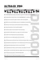
DI4000 User´s Manual Bedienungsanleitung July 1999 ® ULTRA-DI PRO Version 1.0 www.behringer.de 1 E D EC-Declaration of Conformity INTERNATIONAL GmbH acc. to the Directives 89/336/EWG and 73/23/EWG We, BEHRINGER INTERNATIONAL GmbH Hanns-Martin-Schleyer-Straße 36-38 D - 47877 Willich Name and address of the manufacturer or the introducer of the product on the market who is established in the EC herewith take the sole responsibility to confirm that the product: ULTRA-DI PRO DI4000 Type designation and article-No (if applicable) to which this declaration refers, is in accordance with the following standards or standardized documents: x EN 60065 x EN 55020 x EN 55013 x EN 61000-3-2 x EN 61000-3-3 The following operation conditions and installation arrangements have to be presumed: acc. to Operating Manual B. Nier, President Name, address, date and legally binding signature of the person responsible 2 Willich, 01.07.1999 SAFETY INSTRUCTIONS CAUTION: To reduce the risk of electrical shock, do not remove the cover (or back). No user serviceable parts inside; refer servicing to qualified personnel. WARNING: To reduce the risk of fire or electrical shock, do not expose this appliance to rain or moisture. This symbol, wherever it appears, alerts you to the presence of uninsulated dangerous voltage inside the enclosure - voltage that may be sufficient to constitute a risk of shock. This symbol, wherever it appears, alerts you to important operating and maintenance instructions in the accompanying literature. Read the manual. DETAILED SAFETY INSTRUCTIONS: All the safety and operation instructions should be read before the appliance is operated. Retain Instructions: The safety and operating instructions should be retained for future reference. Heed Warnings: All warnings on the appliance and in the operating instructions should be adhered to. Follow instructions: All operation and user instructions should be followed. Water and Moisture: The appliance should not be used near water (e.g. near a bathtub, washbowl, kitchen sink, laundry tub, in a wet basement, or near a swimming pool etc.). Ventilation: The appliance should be situated so that its location or position does not interfere with its proper ventilation. For example, the appliance should not be situated on a bed, sofa rug, or similar surface that may block the ventilation openings, or placed in a built-in installation, such as a bookcase or cabinet that may impede the flow of air through the ventilation openings. Heat: The appliance should be situated away from heat sources such as radiators, heat registers, stoves, or other appliance (including amplifiers) that produce heat. Power Source: The appliance should be connected to a power supply only of the type described in the operating instructions or as marked on the appliance. Grounding or Polarization: Precautions should be taken so that the grounding or polarization means of an appliance is not defeated. Power-Cord Protection: Power supply cords should be routed so that they are not likely to be walked on or pinched by items placed upon or against them, paying particular attention to cords and plugs, convenience receptacles and the point where they exit from the appliance. Cleaning: The appliance should be cleaned only as recommended by the manufacturer. Non-use Periods: The power cord of the appliance should be unplugged from the outlet when left unused for a long period of time. Object and Liquid Entry: Care should be taken so that objects do not fall and liquids are not spilled into the enclosure through openings. Damage Requiring Service: The appliance should be serviced by qualified service personnel when: - The power supply cord or the plug has been damaged; or - Objects have fallen, or liquid has been spilled into the appliance; or - The appliance has been exposed to rain; or - The appliance does not appear to operate normally or exhibits a marked change in performance; or - The appliance has been dropped, or the enclosure damaged. Servicing: The user should not attempt to service the appliance beyond that is described in the Operating Instructions. All other servicing should be referred to qualified service personnel. 3 E ULTRA-DI PRO Professional 4-Channel Active Direct Inject Box DI4000 s Professional and multi-purpose 4-channel Direct Inject box for stage and studio applications s Ultra-flat frequency response due to renowned BEHRINGER OT-1 transformers s Allows direct connection to speaker outputs for more than 3000 Watts s Ultra-low noise audio operational amplifiers for outstanding sound performance s Prevents hum and noise pick up due to special transformer decoupling s Converts unbalanced line inputs to balanced outputs s +20 dB gain switch for pre-amplification of low level signals s Phase Reverse switch allows you to instantly correct phase problems s Switchable High Cut filter (8 kHz) for guitar applications s Ground Lift switch eliminates typical ground loop problems s Accurate eight-segment LED level meter simplifies level setting for optimum performance s Gold-plated XLR connectors and 1/4" TRS connections for input and link output s Switchable attenuation allows for maximum input of +50 dBu s Illuminated switches enable you perfect operation in dark stage environments s High-quality components and exceptionally rugged construction ensures long life and durability s Internal power supply design for professional application s Manufactured under ISO9000 certified Management System 4 FOREWORD Dear Customer, Welcome to the team of ULTRA-DI PRO users and thank you very much for expressing your confidence in BEHRINGER products by purchasing this DI box. It is one of my most pleasant tasks to write this letter to you, because it is the culmination of many months of hard work delivered by our engineering team to reach a very ambitious goal: making an outstanding device that will become a standard tool used by studios and P.A. companies. The task to design the ULTRA-DI PRO certainly meant a great deal of responsibility, which we assumed by focusing on you, the discerning user and musician. It also meant a lot of work and night shifts to accomplish this goal. But it was fun, too. Developing a product usually brings a lot of people together, and what a great feeling it is when everybody who participated in such a project can be proud of what weve achieved. It is our philosophy to share our joy with you, because you are the most important member of the BEHRINGER family. With your highly competent suggestions for new products youve greatly contributed to shaping our company and making it successful. In return, we guarantee you uncompromising quality (manufactured under ISO9000 certified management system) as well as excellent technical and audio properties at an extremely favorable price. All of this will enable you to fully unfold your creativity without being hampered by budget constraints. We are often asked how we can make it to produce such high-grade devices at such unbelievably low prices. The answer is quite simple: its you, our customers! Many satisfied customers means large sales volumes enabling us to get better conditions of purchase for components, etc. Isnt it only fair to pass this benefit back to you? Because we know that your success is our success, too! I would like to thank all people whose help on Project ULTRA-DI PRO has made it all possible. Everybody has made very personal contributions, starting from the designers of the unit via the many staff members in our company to you, the user of BEHRINGER products. My friends, its been worth the trouble! Thank you very much, Uli Behringer 5 E TABLE OF CONTENTS 1. INTRODUCTION ...................................................................................................................... 7 1.1 Before you begin ............................................................................................................................ 8 1.2 Control elements ............................................................................................................................. 8 2. APPLICATIONS ..................................................................................................................... 10 2.1 2.2 2.3 2.4 Tapping signal from a (bass)guitar ................................................................................................ 10 Converting the output of a keyboard / DJ-mixer / headphone plug ................................................ 10 Converting a microphone signal ..................................................................................................... 11 Tapping a signal from a power amplifier output .............................................................................. 11 3. INSTALLATION ...................................................................................................................... 11 3.1 Rack mounting ............................................................................................................................... 11 3.2 Mains connection .......................................................................................................................... 12 3.3 Audio connections ........................................................................................................................ 12 4. SPECIFICATIONS .................................................................................................................. 14 5. WARRANTY ........................................................................................................................... 15 6 1. INTRODUCTION Whether you are on the stage or in the studio, you often find that you need to connect an audio source to your mixing console, but you dont have the appropriate connectors. For example, only few keyboards feature balanced outputs; guitars should not be connected directly to the console; and placing a microphone in front of an amp is not always an ideal solution, because the mic will pick up unwanted signals from other instruments, too. Low frequency signals (e.g. produced by a bass guitar) are particularly difficult to handle using these techniques. "DI" is short for "Direct Injection". A Direct Inject box allows you to use a high-impedance, unbalanced source, e.g. the signal between guitar and guitar amp, and feed it directly into an input channel on your console, without having to use a microphone. And that's far from being all. There are plenty of situations in which you'd like to input unbalanced source signals into your console, and possibly convert them to balanced signals before. As you can expect, the DI4000 offers you a reliable solution. The following explanations will give you an introduction to the complex performance-impedance issue: impedance is defined as the dependence of a device's electrical resistance and phase response on the frequency processed. Thus, impedance is one of the criteria that distinguish good DI boxes from poor ones. Much like in a power amp and its connected speakers, impedance determines the performance of the device. With a good power amp, the load impedance will have little influence on the maximum output power, but it can considerably affect other properties. With a passive DI box, the connected load impedances (ins and outs) alter the bandwidth, frequency response, distortion, etc. of the DI box. By the way: there are two basic types of DI boxes, passive and active. Both can be connected to one of the console's mic inputs. Passive DI boxes offer the advantage that they are less expensive than active models (less electronics, no power supply), however, their performance depends on the connected impedance. With a passive DI box connected, any impedance change on the console side will also modify the input impedance. The frequency response will always depend on the impedances connected. Any passive DI box will only perform properly with accurately specified impedances (high on the input side, low at the output), i.e. it will only work in standard situations. Active DI boxes such as our ULTRA-DI PRO, however, do not suffer from such restrictions, because they use an amplifier circuit to buffer the input signal. Since the ULTRA-DI PRO's input impedance is ultra-high, the signal remains unaffected as it passes through the DI box. Additionally, the ULTRA-DI PRO features balanced impedances on the output side, making the signal less susceptible to hum and noise interference. In this way, the signal as source impedance is completely independent of the console used (and vice versa), which means that the sound remains totally unaffected. The ULTRA-DI PRO uses our proven OT-1 transformer which ensures a clear and distortion-free sound and linear frequency response. Additionally, the ULTRA-DI PRO comes with a built-in power supply. Future-oriented BEHRINGER technology The ULTRA-DI PRO is based on SMD technology (Surface Mounted Devices). These subminiature components known from aerospace applications ensure both extreme packing density and greater reliability. High-quality components and design The philosophy behind BEHRINGER products guarantees a no-compromise circuit design and employs the best choice of components. The op-amps, type 4580, used in the ULTRA-DI PRO are chosen for their superior signal-to-noise ratio, low distortion and linear performance. Additionally, the ULTRA-DI PRO uses high quality resistors and capacitors with very tight tolerances, high-grade switches as well as other selected components. 1. INTRODUCTION 7 E 1.1 Before you begin Your BEHRINGER ULTRA-DI PRO was carefully packed in the factory and the packaging was designed to protect the unit from rough handling. Nevertheless, we recommend that you carefully examine the packaging and its contents for any signs of physical damage, which may have occurred in transit. + If the unit is damaged, please do not return it to us, but notify your dealer and the shipping company immediately, otherwise claims for damage or replacement may not be granted. Shipping claims must be made by the consignee. The BEHRINGER ULTRA-DI PRO fits into one standard 19" rack unit of space. Please allow at least an additional 4" (10 cm) depth for the connectors on the back panel. + Be sure that there is enough space around the unit for cooling and please do not place the ULTRA-DI PRO on high temperature devices such as power amplifiers etc. to avoid overheating. The mains connection of the ULTRA-DI PRO is made by using the supplied cable. It meets all of the international safety certification requirements. Please make sure that all units have a proper ground connection. + Before you connect your ULTRA-DI PRO to the mains, please make sure that your local voltage matches the voltage required by the unit! 1.2 Control elements The BEHRINGER ULTRA-DI PRO has four identical channels. The control elements are identical on all channels. Fig. 1.1: Control and display elements on the front panel OUTPUT. This is the balanced output of the ULTRA-DI PRO. The connection to the mixing desk should be made with a standard high-quality balanced cable. +20 dB gain switch for pre-amplification of low level signals. Switchable HIGH CUT filters (8 kHz) for guitar applications (6 dB/Oct). With the PHASE REVERSE switch the input signal is reversed in phase by 180°. Use the GND LIFT switch to either connect the ground of input and output or keep them completely separate. Depending on the grounding of the connected devices linking or disconnecting will reduce hum or prevent ground loops. GROUND LIFT ON means no interconnection. The OUTPUT LEVEL meter displays the output level of the ULTRA-DI PRO in a range from -24 dB to +18 dB. Use the POWER switch to turn on the BEHRINGER ULTRA-DI PRO. 8 1. INTRODUCTION E Fig. 1.2: Rear panel elements of the BEHRINGER ULTRA-DI PRO LINK. This is the unbalanced parallel output of the ULTRA-DI PRO. Connect this to the input of the backline or monitor amplifier. INPUT. Connect the source to this 1/4" jack to input the signal. + And The -20 dB ATTENUATION switches greatly increase the operating range of the ULTRA-DI PRO. From the low level signals of a high impedance guitar to the hot speaker terminals of a P.A. amplifier. Depressing both will give 40 dB attenuation. Only use the -20 dB switches if you are sure the ULTRA-DI PRO is clipping (overloading) and not your mic pre-amp. Always use as little attenuation as possible to get the best possible signal-to-noise ratio. Before you connect the unit you should check that the voltage indicator on the voltage selector matches your local line voltage. When you need to replace the fuse, please insert a fuse of the same type and rating.The ULTRA-DI PRO is connected to the mains via an IEC power connector. A suitable power cord is enclosed. Please also note the instructions given in chapter 3 INSTALLATION. Please take the time and ask your dealer to fill in the warranty card. Then return it within 14 days after the date of purchase. Otherwise, you will lose your extended warranty rights. Please check that the SERIAL NUMBER on the unit is the same as the one indicated in the warranty card. To provide maximum flexibility the ULTRA-DI PRO is also fitted with an unbalanced XLR INPUT to connect the source. 1. INTRODUCTION 9 2. APPLICATIONS 2.1 Tapping signal from a (bass)guitar Fig. 2.1: Guitar ß DI box ß Guitar Amp/Mixer This figure shows the standard application of any Direct Inject box. The signal to the amplifier is unaffected, it is just tapped off to be routed to the microphone input of the mixer. Especially bass guitars benefit from this application. It is difficult to find a microphone which handles high level low frequencies well and with a linear frequency response. Using the ULTRA-DI PRO will give you clean and crisp sound. Connect the ULTRA-DI PRO after any effects devices, so that their effect will be heard over the P.A.-system or on the recording. 2.2 Converting the output of a keyboard / DJ-mixer / headphone plug Fig. 2.2: DJ-mixer ß 2 x DI box ß Mixer This configuration can be used with a keyboard, DJ-mixer, headphone output, drum kit or any (stereo or mono) line source. In all cases where you want to run long lines, for instance to the FOH (Front Of House) desk. The signal can be linked through to another amplifier, if the keyboard player/ DJ/etc. wants to have a monitor connected independent of the foldback mix. The ULTRA-DI PRO acts as both a ground isolator and an unbalanced to balanced converter. 10 2. APPLICATIONS 2.3 Converting a microphone signal E Fig. 2.3: Connecting a microphone Sometimes all thats available (especially when all other mics are in use) is an unbalanced high impedance microphone with an unbalanced jack. With the ULTRA-DI PRO long cable runs to the console can be established without fear of picking up noise and hum. Just plug the jack into the input and connect the output to the consoles mic input. 2.4 Tapping a signal from a power amplifier output When no line out is available it is possible to connect an amplifier output directly to the DI4000 (for example, recording direct from a guitar amplifier, TV-speaker, etc). It is possible to connect the output, i.e an extra speaker output, of up to 3000 Watts to the ULTRA-DI PRO without fear of overloading. Pay attention to the two -20 dB buttons on the ULTRA-DI PRO! Both must be depressed if an amplifier output is connected to the DI4000 input. Fig. 2.4: Connection to an amplifier output + Always make sure the GROUND LIFT is on (no ground link) when connecting to speaker terminals. This prevents accidental short-circuiting of the amplifier output. Also make sure the tip of the input jack is connected to the red terminal and that the metal housing of the DI4000 has no contact with other equipment. 3. INSTALLATION Your BEHRINGER ULTRA-DI PRO was carefully packed in the factory and the packaging was designed to protect the unit from rough handling. Nevertheless, we recommend that you carefully examine the packaging and its contents for any signs of physical damage, which may have occurred in transit. + If the unit is damaged, please do not return it to us, but notify your dealer and the shipping company immediately, otherwise claims for damage or replacement may not be granted. Shipping claims must be made by the consignee. 3. INSTALLATION 11 3.1 Rack mounting The BEHRINGER ULTRA-DI PRO fits into one standard 19" rack unit of space. Please allow at least an additional 4" depth for the connectors on the back panel. + Be sure that there is enough air space around the unit for cooling and please do not place the ULTRA-DI PRO on high temperature devices such as power amplifiers etc. to avoid overheating. 3.2 Mains connection The mains connection of the ULTRA-DI PRO is made by using a mains cable and a standard IEC receptacle. It meets all of the international safety certification requirements. + Please make sure that all units have a proper ground connection. For your own safety, it is advisable not to remove the ground connection within the units or at the supply, or fail to make this connection at all. Before you switch on the unit, check that it is configured to match your AC mains voltage requirements. If it does not comply, then it is necessary to switch the operating voltage to the correct supply requirements BEFORE turning on the unit, otherwise the unit could be severely damaged. You will find this combined fuse holder/voltage selector at the back, adjacent to the IEC receptacle. IMPORTANT: This does not apply for general export models which are built for one operating voltage only. The AC voltage selection is defined by the position of the fuse holder. If you intend to change the operating voltage, remove the fuse holder and twist it by 180 degrees before you reinsert it. Matching the two markers shows the selected voltage. + If the unit is switched to another operating voltage, the fuse rating must be changed. See the technical specifications in the appendix. A safety fuse protects the unit from serious defects. If the fuse blows, this is a warning sign and always indicates that the circuit is overloaded. The fault must always be repaired before the fuse is replaced. If the safety fuse is faulty and needs replacing after the unit is repaired, please make sure that you replace it only with the identical type and rating. NEVER use fuses of different ratings or cover faulty fuses with aluminium foil. This can cause fire and electric shocks and will endanger your life and the lives of others. 3.3 Audio connections As standard, the BEHRINGER ULTRA-DI PRO is installed with transformer-balanced outputs. This transformer features automatic hum and noise reduction for balanced signals and thus allows for trouble-free operation, even at high operating levels. Externally induced mains hum etc. will be effectively suppressed. + 12 Please ensure that only qualified persons install and operate the ULTRA-DI PRO. During installation and operation the user must have sufficient electrical contact to earth. Electrostatic charges might affect the operation of the ULTRA-DI PRO! 3. INSTALLATION Output Cable Input Ground Pin 1 2 1 1 Shield (+) Signal + Hum (-) Signal + Hum Pin 2 = (+) Signal 3 2 Positive (+)Hum + Signal Negative (-)Hum + Signal E 3 Pin 3 = (-) Signal 2 x Signal = Signal + 6 dB RFI and Hum Fig. 3.1: Compensation of interference with balanced connections Unbalanced use of mono 1/4" jack plugs Balanced use of stereo 1/4" jack plugs Tip = Signal Tip = hot (+ve) Ring = cold (-ve) Sleeve = Ground / Shield Sleeve = Ground / Shield Tip Tip Sleeve Ring Sleeve Strain relief clamp Strain relief clamp For connection of balanced and unbalanced plugs, ring and sleeve have to be bridged at the stereo plug. Balanced use with XLR connectors 2 1 3 1 = Ground / Shield 2 = hot (+ve) 3 = cold (-ve) Input 1 2 3 Output For unbalanced use pin 1 and pin 3 have to be bridged Fig. 3.2: Different plug types 3. INSTALLATION 13 4. SPECIFICATIONS Audio input Connectors Type Impedance Max. input level XLR and 1/4" jack DC-decoupled, unbalanced input max. 220 kOhm +20/+40/+60 dBu Audio output Connectors Type Impedance Max. output level XLR transformer-balanced output stage 600 Ohms balanced +20 dBu System specifications Bandwidth (100 kOhm) Bandwidth (600 Ohm) Bandwidth (High Cut) Noise 23 Hz to 120 kHz (± 3dB) 23 Hz to 27 kHz (± 3dB) 10 Hz to 8 kHz (± 3dB) -95 dBu Power supply Mains voltages Mains connection USA/Canada ~ 120 V AC, 60 Hz U.K./Australia ~ 240 V AC, 50 Hz Europe ~ 230 V AC, 50 Hz General export model ~ 100-120 V AC, ~ 200-240 V AC, 50-60 Hz 10 Watts 100-120 V AC: 200 mA (slow-blow) 200-240 V AC: 100 mA (slow-blow) standard IEC receptacle Physical Dimension Net weight Shipping weight 1 3/4" (44.5 mm) x 19" (482.6 mm) x 7 1/2" (190.5 mm) 2.5 kg 3.5 kg Power consumption Fuse BEHRINGER is constantly striving to maintain the highest professional standards. As a result of these efforts, modifications may be made from time to time to existing products without prior notice. Specifications and appearance may differ from those listed or illustrated. 14 4. SPECIFICATIONS 5. WARRANTY § 1 WARRANTY CARD To be protected by this warranty, the buyer must complete and return the enclosed warranty card (signed/stamped by retail dealer) within 14 days of the date of purchase to BEHRINGER INTERNATIONAL (address see § 3). Failure to return the card in due time (date as per postmark) will void any extended warranty claims. § 2 WARRANTY 1. BEHRINGER INTERNATIONAL warrants the mechanical and electronic components of this product to be free of defects in material and workmanship for a period of one (1) year from the original date of purchase, in accordance with the warranty regulations described below. If any defects occur within the specified warranty period that are not caused by normal wear or inappropriate use, BEHRINGER INTERNATIONAL shall, at its sole discretion, either repair or replace the product. 2. If the warranty claim proves to be justified, the product will be returned freight prepaid by BEHRINGER INTERNATIONAL within Germany. Outside of Germany, the product will be returned at the buyers expense. 3. Warranty claims other than those indicated above are expressly excluded. § 3 RETURN AUTHORIZATION NUMBER 1. To obtain warranty service, the buyer must call BEHRINGER INTERNATIONAL during normal business hours BEFORE returning the product (Tel.: +49 (0) 21 54 / 92 06 66). All inquiries must be accompanied by a description of the problem. BEHRINGER INTERNATIONAL will then issue a return authorization number. 2. The product must be returned in its original shipping carton, together with the return authorization number, to the following address: BEHRINGER INTERNATIONAL GmbH Service Department Hanns-Martin-Schleyer-Str. 36-38 D - 47877 Willich-Münchheide 3. Shipments without freight prepaid will not be accepted. § 4 WARRANTY REGULATIONS 1. Warranty services will be furnished only if the product is accompanied by an original retail dealers invoice. Any product deemed eligible for repair or replacement by BEHRINGER INTERNATIONAL under the terms of this warranty will be repaired or replaced within 30 days of receipt of the product at BEHRINGER INTERNATIONAL. 2. If the product needs to be modified or adapted in order to comply with applicable technical or safety standards on a national or local level, in any country which is not the country for which the product was originally developed and manufactured, this modification/adaptation shall not be considered a defect in materials or workman- ship. The warranty does not cover any such modification/adaptation, irrespective of whether it was carried out properly or not. Under the terms of this warranty, BEHRINGER INTERNATIONAL shall not be held responsible for any cost resulting from such a modification/adaptation. 3. Free inspections, maintenance/repair work and replacement of parts are expressly excluded from this warranty, in particular if caused by inappropriate use. Likewise, the warranty does not cover defects of expendable parts caused by normal wear of the product. Expendable parts are typically faders, potentiometers, switches and similar components. 4. Damages/defects caused by the following conditions are not covered by this warranty: s misuse, neglect or failure to operate the unit in compliance with the instructions given in the user or service manuals. s connection or operation of the unit in any way that does not comply with the technical or safety regulations applicable in the country where the product is used. s damages/defects that are caused by force majeure or by any other condition beyond the control of BEHRINGER INTERNATIONAL. 5. Any repair carried out by unauthorized personnel will void the warranty. 6. Products which do not meet the terms of this warranty will be repaired exclusively at the buyers expense. BEHRINGER INTERNATIONAL will inform the buyer of any such circumstance. If the buyer fails to submit a written repair order within 4 weeks after notification, BEHRINGER INTERNATIONAL will return the unit C.O.D. with a separate invoice for freight and packing. Such cost will also be invoiced separately when the buyer has sent in a written repair order. § 5 WARRANTY TRANSFERABILITY This warranty is extended exclusively to the original buyer (customer of retail dealer) and is not transferable to anyone who may subsequently purchase this product. No other person (retail dealer, etc.) shall be entitled to give any warranty promise on behalf of BEHRINGER INTERNATIONAL. § 6 CLAIM FOR DAMAGES Failure of BEHRINGER INTERNATIONAL to provide proper warranty service shall not entitle the buyer to claim (consequential) damages. In no event shall the liability of BEHRINGER INTERNATIONAL exceed the invoiced value of the product. § 7 OTHER WARRANTY RIGHTS This warranty does not exclude or limit the buyers statutory rights provided by national law, in particular, any such rights against the seller that arise from a legally effective purchase contract. The information contained in this manual is subject to change without notice. No part of this manual may be reproduced or transmitted in any form or by any means, electronic or mechanical, including photocopying and recording of any kind, for any purpose, without the express written permission of BEHRINGER GmbH. BEHRINGER and ULTRA-DI are registered trademarks. ALL RIGHTS RESERVED © 1999 BEHRINGER. BEHRINGER INTERNATIONAL GmbH, Hanns-Martin-Schleyer-Str. 36-38, D-47877 Willich-Münchheide II Tel. +49 (0) 21 54 / 92 06-0, Fax +49 (0) 21 54 / 92 06-30 5. WARRANTY 15 E