1
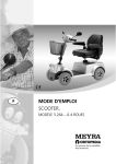
GB
OPERATING MANUAL
ELECTRIC WHEELCHAIR
Model 1.595 – 603 vertical junior
Model 1.595 – 604 vertical senior
We
move
people.
Contents
Introduction .................................................................................................. 6
Indications..................................................................................................... 7
Acceptance .................................................................................................... 7
Adjustment ................................................................................................... 7
Specifications................................................................................................ 8
Use ................................................................................................................. 8
Overview ....................................................................................................... 9
Model: 1.595 – 603 / 1.595 – 604 .........................................................................9
Quick guide ................................................................................................. 10
Driving behavior ........................................................................................ 12
Speed limitation .................................................................................................12
Functional checks ...............................................................................................12
Brakes .......................................................................................................... 13
Operating brakes................................................................................................13
Parking brake .....................................................................................................13
Selection lever.....................................................................................................13
Locking the brake .........................................................................................13
Releasing the brake ......................................................................................13
Drive-/push mode ...............................................................................................14
Selecting the push mode ..............................................................................14
Selecting the motor mode ...........................................................................14
Selecting the operation ............................................................................. 15
Pre-operation checks ..........................................................................................16
Charging procedure ......................................................................................17
Operating module ...................................................................................... 18
Positioning the operating module....................................................................18
Function description .....................................................................................18
Horizontal adjustment..................................................................................18
Turning the operating module to the side .................................................19
Remove the operating module....................................................................20
Fitting of the operating module..................................................................20
2
Arm supports .............................................................................................. 21
Angle of the arm supports ...........................................................................21
Swivelling up the arm supports ...................................................................22
Swivelling down the arm supports ..............................................................22
Back support ............................................................................................... 23
Head support .............................................................................................. 23
Adjustment of the head support .................................................................23
Removing and height adjusting the head support ....................................23
Holder for chin operation ............................................................................23
Leg support ................................................................................................. 24
Folding up the leg support ..........................................................................24
Knee cushions .....................................................................................................25
Removing/attaching the knee cushions ......................................................25
Side cushions .............................................................................................. 26
Adjusting the side cushions ..........................................................................26
Removing the side cushions .........................................................................26
Removing / attaching the side cushion pad................................................26
Back support cushions ............................................................................... 26
Torso supports ............................................................................................ 27
Splay wedge ............................................................................................... 27
Removing/attaching the splay wedge .........................................................27
Chest support ............................................................................................. 28
Removing/attaching the chest support .......................................................28
Depth adjustment of the chest support ......................................................28
Lifting/lowering the chest support ..............................................................29
Seat .............................................................................................................. 30
Seat inclination (camber) ...................................................................................30
Special safety information for raising the seat, seat height adjustment,
standing and lying functions .............................................................................31
Raising the seat ..................................................................................................31
Seat height adjustment .....................................................................................32
Getting up from the sitting position ................................................................33
Lying position .....................................................................................................34
Getting up from the lying position...................................................................35
Adjusting the seat depth ...................................................................................36
3
Chest strap .................................................................................................. 36
Fastening the breast strap ............................................................................36
Opening the breast strap .............................................................................36
Retaining strap ...................................................................................................37
Fastening the retaining strap.......................................................................37
Adjustment of belt length ...........................................................................37
Shoulder strap ....................................................................................................38
Fastening the shoulder strap .......................................................................38
Adjustment of belt length ...........................................................................38
Emergency switch ...................................................................................... 39
Raising the seat .............................................................................................39
Lowering the seat .........................................................................................39
Loading and transportation ...................................................................... 40
Loading ...............................................................................................................40
Transport security ...............................................................................................40
Passenger transport in handicapped transport vehicles (HTV).......................41
Maintenance ............................................................................................... 41
Maintenance .......................................................................................................41
Maintenance schedule ..................................................................................42
Fuses ....................................................................................................................44
Replacing the fuses .......................................................................................44
Tyre damage on pneumatic tyres......................................................................44
Lighting ...............................................................................................................45
Adjusting the headlights ..............................................................................45
Back light .......................................................................................................45
Headlights......................................................................................................46
Indicator .........................................................................................................47
Information for the specialist dealer ................................................................48
Programming the driving behaviour...........................................................48
4
Technical data ............................................................................................. 49
Kilometric performance .....................................................................................49
Fuses ....................................................................................................................50
Lighting ...............................................................................................................50
Vehicle independent data .................................................................................51
Vehicle specific data ...........................................................................................53
Meaning of the labels on the electric wheelchair ...........................................54
Meaning of the symbols on the type plate ......................................................55
Fault correction .......................................................................................... 56
Inspection certificate ................................................................................. 57
Warranty / Guarantee................................................................................. 58
Inspection certificate for transfer .....................................................................59
5
INTRODUCTION
We thank you for the confidence you
have placed in our company by choosing an electric wheelchair from this
series.
The model of your selection, fulfils
the wish for mobility and more independence by way of a new styling of
the proven MEYRA-Ortopedia technology.
With all equipment and their accessories the electric wheelchair offers the
respective adaptation to your disability.
Like any other vehicle, an electric
wheelchair is a technical aid. It is subject to explanations, requires regular
care and can cause danger when used
improperly. The correct handling must
therefore be learned. This operating
manual is to help you get accustomed
to the handling of the electric wheelchair as well as to prevent accidents.
☞ Note:
Please note that the illustrated
equipment variants can deviate
from your model.
– We have therefore also listed chapters with options that might not be
applicable for your vehicle.
!
Attention:
Read and observe the following
documentation belonging to the
electric wheelchair before first use:
– this operating manual,
– the operating manual < Operating
module NEMO >,
– the safety and general handling instructions < Electronic vehicles >.
6
☞ Note:
Children and juveniles should read
the documentation belonging to
the electric wheelchair together
with their parents respectively a
supervisor or accompanying person before first use.
For users with visual impairments the
PDF-files of the above mentioned documents can be accessed on our website < www.meyra-ortopedia.com >.
☞ Contact your specialist dealer
when required.
Alternatively users with visual impairments can have the documentation
read out by a helper.
INDICATIONS
ADJUSTMENT
If the following indications occur we
recommend the application of this
mobility product:
☞ Note:
The first adjustment of the electric
wheelchair to the user as well as
the required handling introduction is carried out by educated personnel.
☞ Walking disability resp. extremely
limited walking ability as part of
the basic need to move around in
your own home.
☞ The need to be able to leave home
for a short walk in fresh air or in order to reach the places, commonly
in the perimeter of the home, required to fulfil basic needs.
The electric wheelchair is handed over
to the user in an operationally ready
state under observance of all relevant
safety regulations and adjusted to the
individual requirements.
☞ Note:
Existing manual adjustments are to
be adjusted for the drive mode in
such a fashion that a secure handling of the electric wheelchair is
warranted.
ACCEPTANCE
All products are checked for faults
in the factory and packed in special
boxes.
☞ Note:
However, we request that you
check the vehicle for possible
transport damage immediately on
receipt – preferably in the presence of the carrier.
☞ Note:
The packaging of the electric
wheelchair should be stored for a
further transport that might become necessary.
!
Attention:
Always have retrospective adaptation and adjustment work carried
out by a specialist dealer.
☞ Note:
☞ We recommend a regular control
if the wheelchair adjustment in order to ensure a long-term optimal
provision even with changing illness/handicap patterns of the user.
☞ Especially for children and juveniles an adjustment every 6 months
is recommendable.
7
SPECIFICATIONS
The electric wheelchair is an environment-friendly electronic vehicle. It is
a multifunction wheelchair, compact
and agile with reclining and rising
functions, especially designed for the
extreme provision of adolescents and
adults, for indoor and outdoor use on
level, firm surfaces.
With all equipment and their accessories the electric wheelchair offers die
respective adaptation to your respective disability.
☞ The model has been assigned the
'Use Class B' as per the EN12184
standard.
USE
The electric wheelchair is solely designated to transport one person instructed in its use. Other pulling or
transporting uses do not comply with
its intended purpose.
Before use on outdoor public routes
the electric wheelchair is to be fit with
an optionally available lighting jig.
Depending on the leg support adjustment it can cross obstacles with a max.
height of 40 mm resp. 70 mm.
☞ Adjust the seat or leg support for
the required ground clearance of
the leg support-support castors to
overcome obstacles.
8
OVERVIEW
Model: 1.595 – 603 / 1.595 – 604
The overview shows the most important components and operating equipment.
1
2
3
10
11
12
4
5
6
14
9
8
7
Pos. Description
1
2
3
4
5
6
7
8
9
13
Breast strap
Back support upholstery
Arm support
Side cushion
Knee cushion
Calf pad
Leg support / Footplate
Leg support-support castor
Selection lever drive-/push mode
Pos. Description
10
11
12
13
14
Seat unit
Head support
Operating module
Drive wheel
Steering wheel
9
QUICK GUIDE
Locking down the adjustments
☞ Note:
1. The leg support adjustment is
locked when the reclining function
is activated.
☞ First bring the reclining function
into the basic position.
The following quick guide does not
replace the reading and observing
of the documentation belonging
to the wheelchair.
Operation of the adjustments
through the operating module
6 adjustment menus can be selected
with the Mode – key:
☞ Back support with arm support adjustment
☞ Camber/ seat inclination
☞ Leg supports with length alignment adjustment
☞ Reclining function
☞ Seat height adjustment
☞ Standing function
After selecting the menu the adjustment from the basic position can
be activated with the Plus - key, right
turn signal - key or by moving the joystick to the right.
After selecting the menu the adjustment into the basic position can
be activated with the Minus - key, left
turn signal - key or by moving the joystick to the left.
10
2.
During the adjustment from the
lying position into the standing position other adjustment functions,
with the exception of the back
support adjustment, are locked.
3. All other adjustment functions are
locked when the standing function
is activated.
4. The speed is limited to 3 km/h
when the seat height adjustment is in the base position or less
than 10 mm below or more than
100 mm above the base position.
External adjustment keyboard
The adjustments can be activated directly through the external adjustment keyboard.
The two upper keys correspond to the
first adjustment menu:
1.
☞ The right keys correspond to the
2.
plus-key and the left keys the minus-key of the operating module.
3.
1. Back support with arm support adjustment
4.
2. Camber/ seat inclination
5.
3. Leg supports with length alignment adjustment
6.
4. Reclining function
5. Seat height adjustment
6. Standing function
11
DRIVING BEHAVIOR
Optimising the driving behaviour of
the electric wheelchair with the personal circumstances is to be co-ordinated by our customer service technician and your specialist dealer or
therapist.
The adaptability offers sufficient driving comfort as well as a high operating safety.
You determine the speed and driving direction yourself when driving
through the movement of the joystick
and the maximum top speed setting
of your electric wheelchair.
Speed limitation
The speed limitation to 3 km/h serves
the safety and is activated in the following settings:
☞ Seat height lower than 10 mm
☞ Seat height higher than 100 mm
☞ Back support in final position
☞ Reclining function in final position
☞ From the start of the rising function
12
Functional checks
The functions and safety of the electric wheelchair must be checked before the start of each journey.
☞ For this observe chapter < Inspections before starting to drive > in
the Operating manual of the Operating module NEMO.
BRAKES
Operating brakes
3
The motors work electrically as operating brake and carefully brake the
electric wheelchair down without
jerks to stillstand.
Parking brake
1
The parking brakes only work when
the selection lever is in the drive
mode position. They disengage automatically when the wheelchair starts
off. They are disengaged manually by
moving the selection lever to the push
mode position. Also view chapter <
Drive-/push mode >.
Selection lever
2
Locking the brake
Swivel the selection lever forward as
far as possible [1].
!
Attention:
It is impossible to push the electric
wheelchair when in drive mode.
• Inadvertently knocking the control
lever will set the electric wheelchair in motion without control! –
Danger of accidents!
• The brake performance reduces
with
the brake pads are worn.
Releasing the brake
Activate the pull knob (3) on the selection lever and swivel the selection
lever back as far as possible [2].
!
Attention:
Do not get into/out of the electric
wheelchair unless it is switched off
and the selection lever has been
set to "drive mode"!
13
Drive-/push mode
1
The lever (1) for switching the drive
motors between the drive mode and
push mode is located on the right side
of the electric wheelchair.
Attention:
Push the electric wheelchair only
for manoeuvring or in emergency
cases but never on gradients.
• The electric magnetic brakes are
switched off in the push mode. A
braking of the electric wheelchair
is then only possible by switching
to the drive mode. Therefore do
not switch to the push mode on
gradients.
!
3
2
Selecting the push mode
1. Switch off the operating module
because the pushing will otherwise
be made difficult by the electric
system.
2. Pull the locking sleeve (3) up and
then push the selection lever to
the rear [4].
☞ The electric wheelchair can now be
pushed.
Selecting the motor mode
1. Push the selection lever to the
front (1) until it audibly latches [2].
2. Switching the operating module
on. The vehicle is now ready for
use.
14
4
SELECTING THE OPERATION
1
In order to obtain operational readiness of the electric wheelchair the following directions are to be carried out
in the indicated order.
1. Shift to drive mode
Swivel the selection lever forward as
far as possible (1).
2. Check the correct fit of the battery/mains fuse
2
The fuse for the main current has to
sit tightly in the fuse holder (2).
3. Checking the position of the
operating module
The operating module should be positioned in such a way that you can
comfortably and safely steer the electric wheelchair.
☞ Therefore observe chapter < Positioning the operating module >.
3
15
4. Switching the operating module on
Press the ON/OFF-key on the control
panel of the operating module.
☞ Observe the operating manual
< Operating module NEMO >.
☞ Note:
Only actuate the joystick (1) after
the self-test of the electronics has
been completed!
Pre-operation checks
Before starting to drive, the following
should be checked:
☞ the battery charge level,
☞ the pre-selected maximum top
speed setting.
– For this observe the operating manual < Operating module
NEMO >.
16
1
Charging procedure
1. Switch the operating module off.
The selection lever should be in the
drive mode position.
2. Insert the battery charger plug
into the operating module (1).
!
Attention:
Do not insert any objects other
than the battery charger plug into
the battery charging socket. – Danger of short circuit!
3. Switch on the battery charger, respectively, plug the mains plug of
the battery charger into a convenient mains socket. The battery is
now charging.
☞ The charging process only runs
with an intact battery fuse (2)!
1
2
4. Disconnect the battery charger
from the mains socket at the end
of the charging process and then
pull the charging plug out of the
operating module.
17
OPERATING MODULE
Positioning the operating
module
Function description
You will find a detailed description of
the keys and symbols in the operating
manual for < Operating module >.
1
The position of the operating module
can be adjusted to suit the individual
size of the user. The operating module
can also be removed for transportation or storage and can be laid on the
seat or stored separately.
!
Attention:
Switch off the operating module
before adjusting/removing it.
Horizontal adjustment
Slacken the clamping screw (1) for
horizontal adjustment. Slide the operating module into the desired position and in doing so carefully guide
the cable along. Retighten the clamping screw again securely.
18
2
Turning the operating module to
the side
With the optional swivel away operating module adapter the operating
module can be swivelled back to the
side (1) so that it is located parallel to
the arm support. This makes it possible, for example:
– to drive closer to a table,
1
– remove the operating module
more easily.
For regular drive mode the operating
module can be swivelled back toward
the front until it engages back into
the locking catch (2).
☞ Note:
☞ Press it toward the swivelling device for easier swivelling.
2
☞ Should the operating module be
positioned too close to the arm
support, move it slightly forward
before swivelling.
!
Attention:
Do not grab into the area of the
cross brace. – Danger of jamming!
19
Remove the operating module
Swivel the operating module to the
side first before removing it (1).
– Loosen the clamping screw (4) of
the clamping guide and pull the
operating module out toward the
front.
☞ Carefully route the cable when do-
1
ing this.
Fitting of the operating module
– For drive mode insert the operating module from the front into the
bracket.
– Swivel the operating module back
to the front until it locks into place.
– Adjust the operating module to
the desired height and retighten
the clamping screw (4).
☞ Carefully route the cable when doing this.
20
4
ARM SUPPORTS
The arm supports can be adjusted in
height by a specialist dealer to suit the
needs of the user.
!
Attention:
Do not use the arm supports to lift
or carry the wheelchair.
1
Angle of the arm supports
The angle of the arm supports can be
adjusted to the desires of the user.
☞ Note:
During the electric adjustment of
the back support the arm supports
are automatically raised/lowered
into a comfortable position of the
arm support pads (1).
21
Swivelling up the arm supports
The arm supports can be swivelled upward when necessary (1).
– Pull out the button (2) that locks
down the arm support and swivel
the arm support up as far as possible.
☞ Note:
☞ Support the arm support slightly
1
with one hand. – This makes it easier to use the locking button of the
arm support.
☞ The button (2) that locks the arm
support must visibly lock into place
again (3).
2
Swivelling down the arm supports
– Pull out the button (2) that locks
down the arm support and swivel
the arm support down as far as
possible (4).
☞ Note:
The locking button (2) of the arm
support must visibly lock into place.
2
3
4
22
BACK SUPPORT
1
The angle of the back support (1) can
be adjusted through the operating
module.
☞ Note:
☞ Also view chapter < Angle of the
arm supports >.
HEAD SUPPORT
2
The head support (2) is swivel proof,
height and depth adjustable as well as
removable.
3
3
☞ Note:
We recommend the fitting of a
rear-view mirror for driving with a
head support.
5
4
Adjustment of the head support
After loosening the clamping levers
(3) the head support can be adjusted
to the desired position.
Afterwards retighten the clamping levers (3).
Removing and height adjusting
the head support
Loosen the clamping screw (4) to remove or adjust the head support. Either remove the head support or slide
it to the desired position. Afterwards
retighten the clamping screw (4).
Holder for chin operation
The holder (5) exists for example in
combination with the chin operation.
23
LEG SUPPORT
The angle of the leg support (1) can
be adjusted through the operating
module.
☞ Note:
☞ The positive and negative final position of the leg support can be set
by a customer service technician.
1
☞ For driving outdoors and in order
to be able to overcome obstacles,
watch for sufficient ground clearance of the front leg support-support castors (2).
Folding up the leg support
To reduce the overall length, e.g. for
transport, the footplate (3) can be
folded upward.
24
2
2
3
Knee cushions
The knee cushions (1) are height and
depth adjustable as well as removable.
Removing/attaching
cushions
the
knee
1
In order to remove/attach the knee
cushions, pull up the locking lever (2)
first. Afterwards remove (3) or attach
(4) the knee cushions.
☞ Check the locking function after
placing them and letting go of
locking lever.
2
4
3
25
SIDE CUSHIONS
1
The side cushions (1) are height, seat
width and depth adjustable as well as
removable.
Adjusting the side cushions
2
After loosening the clamping lever (2)
the respective side cushion can be adjusted to the desired height and position. Afterwards retighten the clamping lever (2).
Removing the side cushions
After loosening the clamping lever (2)
the respective side cushion can be removed or inserted.
Afterwards retighten the clamping lever (2).
3
Removing / attaching the side
cushion pad
Loosen the respective velcro strap (3)
in order to remove the side cushion
pads.
Press the side cushion pad onto the respective carrier plate to reattach them
(closing the velcro strap).
BACK SUPPORT CUSHIONS
The back support cushions (4) are slid
between the back shell and back support upholstery.
For this pull the back support upholstery forward and position the respective back support cushion (4).
26
4
TORSO SUPPORTS
The torso supports (1) are continuously height, width and depth adjustable
as well as removable.
SPLAY WEDGE
The splay wedge (2) can also be
mounted retrospectively in a specialist workshop.
Removing/attaching
wedge
the
1
splay
Loosen the clamping screw (4) for removal (3) and attachment (5).
☞ Retighten the clamping screw (4)
after attaching as well as removing
the splay wedge.
☞ The splay wedge is to be removed
before activating the electrically
lowering footboard.
4
2
3
27
CHEST SUPPORT
The chest support (1) stabilises the
upper body especially in the upright
position.
Removing/attaching
support
the
chest
Loosen the clamping screw (3) on
both sides in order to remove/insert
the chest support.
1
☞ Note:
Secure the chest support with one
hand against unintentionally falling down.
Afterward remove the chest support
(2) or insert it at level height (1).
☞ In order to clamp the chest support, the tip of the clamping screw
(3) must be screwed into the desired dent of the telescopic tube.
2
Depth adjustment of the chest
support
Contact your specialist workshop for
depth adjustment of the chest support.
3
28
Lifting/lowering the chest support
After loosening the clamping screw
(5) on both sides, disconnect the
toothing and turn the chest support
to the desired position (6).
!
•
5
Attention:
In doing so watch for a stable support function in the upright position.
Observe that no objects, such as
pens, snaps, buttons or similar are
located between the chest cushion
and body. – Danger of pressure
sores.
Afterwards retighten the clamping
screw (5) on both sides.
☞ Note:
In doing so the teeth of the angle
adjustment must join again
!
6
Attention:
Ensure the secure fit of the chest
support.
29
SEAT
☞ Note:
☞ Observe the operating manual
< Operating module NEMO >.
☞ Observe chapter < Technical data >.
Seat inclination (camber)
The seat inclination (1) can be adjusted through the operating module.
1
30
Special safety information
for raising the seat, seat
height adjustment, standing and lying functions
!
Attention:
Only drive on slopes, inclines and
obstacles in the basic position
of the seat rising function, seat
height adjustment and the standing resp. lying function. – Danger
of overturning!
1
☞ Note:
☞ All following adjustment functions
should be practised with an attendant or helper.
Raising the seat
After reaching the maximum seat
inclination, after 3 seconds further
activation through the operating
module, the seat is raised in the back.
– This enables you to obtain a raised,
horizontal sitting position (1).
☞ The additional seat raising is
150 mm.
31
Seat height adjustment
The seat height (1) can be adjusted
through the operating module.
☞ This continuously increases the
seat height by up to 300 mm.
☞ In combination with the additional seat raiser of 150 mm the seat
height can now be increased up to
450 mm.
Positive activation:
With positive activation through the
operating module the seat moves upward (1).
☞ Note:
If the seat is moved upward by
more than 100 mm from the basic position, the speed is limited
to 3 km/h and the acceleration
damped.
Negative activation:
With negative activation through the
operating module the seat returns to
the basic position.
☞ The limitation to speed and acceleration are cancelled.
32
1
Getting up from the sitting
position
The rising (1) can be adjusted through
the operating module.
☞ Note:
☞ Rising (1) may only be carried out
with the breast strap (2) applied
and with correctly adjusted knee
cushions (3).
☞ Therefore observe chapter < Knee
3
cushions > and < Chest strap >.
Positive activation:
With positive activation through the
operating module the adjustment
functions first return into a predefined position.
Then the length alignment is slid to
the floor in order to ensure a safe
stand on the leg support-support castors and the seat is raised (1).
☞ Note:
If the seat is moved from the basic
position, all adjustment functions
are blocked and the speed is limited to 3 km/h as well as the acceleration damped.
1
2
Negative activation:
With negative activation through the
operating module the seat returns to
the basic position. The length alignment drives back in and the adjustment functions are all released again.
The limitation to speed and acceleration are cancelled.
33
Lying position
2
The lying position (1) can be adjusted
through the operating module.
☞ Note:
☞ The lying position (1) may only be
set with correctly adjusted knee
cushions (2) and the breast strap
applied (3).
1
☞ Therefore observe chapter < Knee
cushions > and < Chest strap >.
Positive activation:
With positive activation through the
operating module the seat inclination
first return into the basic position.
Then the leg support, length alignment, back and arm supports are
driven into the lying position (resting
position).
☞ Note:
If the back is reclined far toward
the back a seat inclination is no
longer permitted. The speed is limited to 3 km/h and the acceleration
decreased.
Negative activation:
With negative activation through the
operating module the leg support,
length alignment, back and arm supports drive back into the basic position. The adjustment functions are
released.
The limitation to speed and acceleration are cancelled.
34
3
Getting up from the lying
position
Rising (1) from the lying position (2)
can be adjusted through the operating module.
4
☞ Note:
☞ Rising (1) may only be set with correctly adjusted knee cushions (3)
and the breast strap applied (4).
☞ Therefore observe chapter < Knee
cushions > and < Chest strap >.
3
Positive activation:
With further positive activation after
reaching the lying position, 3 seconds
later the arm supports are brought
into a 90°-setting and the seat erected.
1
☞ Note:
☞ If the seat is moved from the basic
position, all adjustment functions,
with the exception of the back
support adjustment are locked and
the speed is limited to 3 km/h as
well as the acceleration damped.
Negative activation:
In the case of a negative activation
through the operating module the
leg supports, length alignment, back
support and arm supports first drive
into the lying position and then back
into the basic position. The adjustment functions are released.
The limitation to speed and acceleration are cancelled.
2
35
Adjusting the seat depth
The seat depth can be adjusted by repositioning the back support (1).
!
Attention:
A retrospective repositioning of
the back support is only to be carried out in a specialist workshop!
1
CHEST STRAP
The breast strap (2) prevents falling
forward.
2
Fastening the breast strap
Pull both straps forward and place
close to the body. To close the velcro
fastener, place both straps on top of
each other and press.
!
Attention:
Make sure that no objects are
trapped between belt and the
body! – Thus you avoid painful
pressure points.
☞ Note:
The breast strap should not be
pulled too tight.
Opening the breast strap
To open the breast strap pull the loop
(3) of the velcro fastener forward (4).
36
4
3
Retaining strap
The retaining strap serves to strap in a
person sitting in the wheelchair.
– Additional stabilisation of the sitting position.
– Prevents the user from falling forwards out of the wheelchair.
1
– Continuous adjustment to suit the
user’s needs.
The retaining strap is screwed on,
from the outer side, at the respective
back support holder.
!
2
Attention:
The retaining strap is not part of
the retaining system for the wheelchair and/or user during transport
in a handicapped transport vehicle.
3
Fastening the retaining strap
Pull both belt halves to the front and
slide the catch halves together so that
they latch together. Then carry out a
pull test.
To open the retaining strap the red
locking button (1) is pressed down.
!
Attention:
Make sure that no objects are
trapped between belt and the
body! – Thus you avoid painful
pressure points.
Adjustment of belt length
☞ Note:
The retaining strap should not be
pulled too tight.
The length of the lap seatbelt can be
changed by pulling the end of the
strap (2).
To reposition the end of the strap (2)
the clamp (3) is activated.
37
Shoulder strap
The shoulder strap (1) serves for additional fixation of a person sitting the
wheelchair.
– Additional stabilisation of the sitting position.
– Prevents falling forward.
– Continuous adjustment to suit the
user’s needs.
The shoulder strap is screwed on, from
the outer side, at the respective back
support holder.
!
Attention:
The shoulder strap is not part of
the retaining system for the wheelchair and/or user during transport
in a handicapped transport vehicle.
Fastening the shoulder strap
Pull both belt halves to the front and
slide the catch halves together so that
they latch together. Then carry out a
pull test.
!
Attention:
Make sure that no objects are
trapped between belt and the
body! – Thus you avoid painful
pressure points.
To open the shoulder strap the red
locking button (2) is pressed down.
Adjustment of belt length
☞ Note:
The shoulder strap should not be
pulled too tight.
To adjust the length hold the respective strap buckle (3) at a right angle to
the strap and position it accordingly.
38
3
1
2
3
EMERGENCY SWITCH
In case of an electric failure the seat
can be raised through the emergency
switch (1)+(2), in order to be able to
reach the controller and batteries.
1
2
Raising the seat
To raise the seat press the lever (1) up
first, then activate the button (2) until
the desired height is reached.
☞ After releasing the button (2) the
seat remains in the same height.
Lowering the seat
To lower the seat press the lever (1)
down first, then activate the button
(2) until the desired height is reached.
☞ After releasing the button (2) the
seat remains in the same height.
39
LOADING AND TRANSPORTATION
☞ Do not use the back support, leg
supports, arm supports or revetments to lift the electric wheelchair!
!
1
Attention:
The electric wheelchair must be
switched off before lifting!
Loading
The electric wheelchair can be loaded
with the aid of ramps or lifting platforms.
☞ Note:
Observe safety and general handling instructions < Electronic vehicles > chapter < Ramps and lifting
platforms >.
2
Transport security
The electric wheelchair is only to be
secured through the securing points
(1) and (2).
☞ The anchor positions are marked
with the symbol (3).
☞ The procedure for securing the
wheelchair can be read in the document < Safety and general handling instructions electronic vehicles > chapter < Transport in motor
vehicles or with conveyors >.
40
3
Passenger transport in
handicapped transport vehicles (HTV)
To determine if your electric wheelchair is approved as a seat for transport inside an HTV, please look at the
type plate.
Attention:
Subsequently, firmly attached parts
of non-original parts to your electric wheelchair are not approved
for person transportation within
an HTV.
☞ This also includes our optional
equipment:
– Code 870; Bracket for oxygen
bottle
– Code 4657; Bracket for respirator
!
MAINTENANCE
An incorrect or neglected cleaning
and maintenance results in a limitation of the product liability.
Maintenance
The following maintenance schedule
gives you a guide for carrying out the
maintenance.
☞ They do not give information
about the actual extent of work
required on the vehicle.
Securing the wheelchair
The procedure for securing the electric wheelchair can be viewed in chapter < Transport security >.
41
Maintenance schedule
WHEN
WHAT
REMARK
Before starting out
General
Carry out test yourself
or with a helper.
Test for faultless operation.
Checking the magnetic brake
Carry out test yourself
or with a helper.
Switch the selection lever drive- / push mode
to drive mode.
If the electric wheelchair can be pushed,
have the brakes repaired immediately in
a specialist workshop.
– Danger of accidents!
Especially before driving in the dark
Lighting
Carry out test yourself
or with a helper.
Every 2 weeks
(depending on
tance covered)
Check air pressure of
the tyres
Before starting out
Every 2 weeks
(depending on
tance covered)
dis-
Check the light- and
indicator signal equipment as well as reflectors for immaculate
performance
Tyre filling pressure:
2.5 bar = 36 psi
Adjustment screws
dis-
Screws and nuts are to
be checked for tight fit.
Carry out test yourself
or with a helper.
Use a tyre gauge.
Carry out test yourself
or with a helper.
Retighten the loosened
adjustment screws.
Contact specialist workshop upon demand.
42
WHEN
WHAT
REMARK
Every 6-8 weeks
(depending on distance covered)
Wheel attachments
Do it yourself or with
the aid of a helper.
Screws and nuts are to
be checked for tight fit
Securely tighten any
loosened wheel nuts or
screws and retighten
again after 10 operating hours or resp. 50
km.
Contact specialist workshop upon demand.
Every 2 months
(depending on
tance covered)
Check tyre profile
dis-
Minimum tread = 1 mm
Carry out a visual check
yourself or with a helper.
If the tyre profile is
worn down or if the
tyre is damaged, consult a specialist workshop for repairs.
Every 6 months
(depending on
quency of use)
Check
fre-
– Cleanness.
See Care.
– General condition.
See Repairs.
Do it yourself or with
the aid of a helper.
Manufacturer
mendation:
recom-
Every 12 months
(depending on frequency of use)
Safety inspection
– Vehicle
To be carried out by
the specialist dealer.
– Battery charger
43
Fuses
Replacing the fuses
Before replacing fuses, park the electric wheelchair on a level surface and
move the selection lever to the drive
mode position to prevent the wheelchair from moving. Switch off the operating module.
!
1
Attention:
Only replace the safety fuse with a
safety fuse of the same type!
New safety fuses are available at all
petrol stations.
2
☞ Note:
If the safety fuse blows again, take
the battery to a specialist dealer
for repair.
Fuse
Mains-/battery fuse (1)
The blade fuse for the battery current
is fit into the fuse holder (2).
Tyre damage on pneumatic
tyres
☞ Please observe the < Technical
☞ For repairing tyre damage we rec-
data >!
44
ommend the use of a foam cartridge that is available in speciality shops. – Afterwards look up a
specialist workshop as soon as possible.
Lighting
(Option)
☞ Note:
If a turn-signal bulb is defective,
the remaining one blinks at double
frequency.
Adjusting the headlights
1
Vertical alignment
☞ The headlights should be set in
such a way that the light cone is
visible on the road. – The lower
edge of the light cone should be
set at distance of 3 meters to the
front of the wheelchair.
Press down the dispersion disc (1) at
the upper or lower edge in order to
adjust the headlights.
2
Back light
2x LED:
☞ Note:
A defective back light bulb is to be
replaced by a specialist workshop.
45
Headlights
Filament bulb:
6V/2.4W PX13.5s
☞ Note:
Use a dry cloth to hold the glass
body of the new filament bulb.
Removal
1
– Switch off the operating module.
– Pull out the main fuse.
– Turn the rear lamp housing counter-clockwise by about 15° (1) and
remove it (2). – In doing so hold
onto the dispersion disc to prevent
it from also turning.
– Pull the defective bulb out of the
dispersion disc.
2
Mounting
– Insert the new bulb into the dispersion disc (2).
☞ Note:
Do not touch the halogen bulb
with bare hands.
– Place the rear lamp housing onto
the dispersion disc with an about
15° counter-clockwise turn (1) and
turn clockwise about 15° to let it
lock into place (3). – In doing so
hold onto the dispersion disc to
prevent it from also turning.
46
3
Indicator
2
Spherical bulb:
24V/21W BAY9s
1
☞ Note:
Use a dry cloth to hold the glass
body of the new filament bulb.
☞ Also a clean paper slip, slid around
the bulb in a sling, can be used to
exchange the bulb.
Removal
– Switch off the operating module.
3
– Pull out the main fuse.
– Insert a small slot screw driver into
one of the two lateral slots (2) and
the wedge off the dispersion disc
(1) carefully.
– Press defective ball lamps lightly,
if necessary slung with a strip of
paper, turn it and pull it from the
socket.
4
Mounting
– Replace a new ball lamp, if necessary slung in a paper strip. – Push
the side pins (bayonet catch) into
the recesses of the bulb holder,
press lightly against the spring and
then turn the bulb until the bayonet catch clicks into place.
– Mount the dispersion disc. – Insert
the spring first with the thin end
(3), then carefully press the dispersion disc on (4).
☞ The locking device of the second
spring must audibly engage.
47
Information for the specialist dealer
A service manual containing a check
list for the annual inspection is available on request.
The functional tests necessary for the
inspection are listed in the check list.
They are a guide for the performance
of the inspection work.
☞ Note:
It does not outline the actual scope
of the necessary work which can
only be ascertained by an inspection of the vehicle.
Programming the driving behaviour
The driving behavior of the electric
wheelchair can be adjusted through
the programming device.
☞ Therefore observe the respective
< Service manual >.
The driving behaviour of the electric
wheelchair should be adjusted to
the individual requirements and the
learning process of the respective user
at regular intervals.
☞ The programming must be specially tailored to the user. The capacity of reaction, the constitution as
well as physical and psychical abilities are to be considered. A talk
with the doctor or therapist can be
very helpful.
After the successful completion of an
annual inspection the inspection certificate should be recorded in the operating manual.
A template for additional inspection
certificates can be copied from the
operating manual when needed. It
then has to be added to the operating manual.
48
!
Attention:
Any change to the manufacturer
set programming may result in an
increased danger of accidents.
☞ Possible danger of tilting in curves.
TECHNICAL DATA
The kilometric performance is greatly
reduced by:
Kilometric performance
– frequent uphill driving,
Kilometric performance depends to a
large extent on the following factors:
– poor drive battery charge condition.
– battery condition,
– low ambient temperature
(e.g. in winter),
– weight of the driver,
– driving speed,
– frequent starting and stopping
(e.g. in town traffic),
– driving style,
– aged, sulphated drive batteries,
– road surface condition,
– frequently necessary steering manoeuvres,
– driving conditions,
– ambient temperature.
The nominal values given by us are realistic under the following conditions:
– Ambient temperature of 27 °C.
– 100 % rated drive battery capacity
as per the DIN standard.
– reduced driving speed (especially
at walking speed).
In practical use, the kilometric performance under 'normal conditions' is
then reduced to approx. 80 % – 40 %
of the nominal value.
– new condition of the drive batteries with more than 5 charging cycles.
– Nominal load of 75 kg.
– Without repeated acceleration.
– Level, firm driving surface.
49
Fuses
Hereto observe chapter < Fuses >.
Mains-/battery fuse
CAN-Bus: 80 A
Lighting
Headlight: 6 V / 2.4 W PX13.5s
Indicator: 24 V / 21 W BAY9s
50
TECHNICAL DATA
All data within the following table relates to the standard version of the stated
model.
Dimensional tolerance ± 1,5 cm, ± 2°.
Short form of wheelchair dimensions:
SH = Seat height
SW = Seat width
SD = Seat depth
BH = Back support height
Vehicle independent data
Type plate: ............................................................... at the side of the chassis frame
Class of use as per EN 12184: ...........................................................................Class B
Life span / Operation span: ............................................................................. 5 years
Sound level: ................................................................................................ < 70 dB(A)
Electrical system:
Drive control: ................................................................................... 24 V / 50 A max.
Engine output: .................................................................................................. 300 W
Main fuse.............................................................................................................. 80 A
Dimensions:
Overall height (without head support): .................................................... 1130 mm
Overall width: ................................................................................................ 650 mm
Overall length (incl. footplate): .................................................................. 1200 mm
Overall length (footplate up-folded): .......................................................... 950 mm
Seat:
Height: ................................................................................................................56 cm
Height with actuator (min./max.): .....................................................86 cm / 101 cm
Inclination, electric (min./max.): .....................................................................0° / 25°
Back support height (BH):
Height: ................................................................................................................58 cm
Adjustment angle (electric): .......................................................................... 0° – 80°
Leg support:
Adjustment angle (electric): .......................................................................... 7° – 90°
Transport dimensions:
Length (footplate up-folded): ..........................................................................95 cm
Width: ................................................................................................................ 65 cm
Height: ..............................................................................................................105 cm
51
Climatic data:
Ambient temperature: .................................................................... -25 °C to +50 °C
Storage temperature with drive batteries: .................................... -25 °C to +50 °C
Storage temperature without drive batteries:............................... -40 °C to +65° C
Chassis:
Drive wheel (pneumatic tyres, max. 2.5 bar):....................365 x 84 mm (3.00 – 8“)
Steering wheel (pneumatic tyres, max. 2.5 bar): ........230 x 70 mm (230/70 – 112)
Drive batteries:
Sealed drive batteries: ........................................ 2 x 12 V 60 Ah (5 h) / 73 Ah (20 h)
Max. battery dimensions (LxWxH): ............................................ 26 x 17.1 x 20.9 cm
Range (see Kilometric performance):
with drive batteries, sealed
60 Ah (5 h) with 6 km/h:..................................................................... approx. 35 km
60 Ah (5 h) with 10 km/h:................................................................... approx. 30 km
Battery charger:
for batteries from 50 Ah (20 h) ..................................................................24 V / 8 A
Performance (see Kilometric performance):
Max. forward top speed: ........................................................... approx. 6 / 10 km/h
Obstacle crossing upwards (without additional support castors): .............. 70 mm
Obstacle crossing upwards (with additional support castors): .................... 40 mm
Obstacle crossing downwards (without additional support castors): ......... 70 mm
Obstacle crossing downwards (with additional support castors): ............... 40 mm
min. turning radius: ......................................................................... approx. 700 mm
min. turning area: ........................................................................................ 1200 mm
Max. permissable rising gradient: .............................................................. 7° (12 %)
Max. permissable falling gradient:............................................................. 7° (12 %)
Max. permissable transverse gradient: ...................................................... 7° (12 %)
Static tilting safety in all directions: ........................................................... 9° (16 %)
52
Weights (basic equipment):
Max. permitted total weight: ......................................................................... 295 kg
Permitted axle load front:............................................................................... 240 kg
Permitted axle load rear: ................................................................................ 180 kg
Max. permissible user weight: ........................................................................ 100 kg
Max. user weight (during handicapped transport): ..................................... 100 kg
Max. additional loading: ....................................................................................10 kg
Empty weight (with 60 Ah sealed drive batteries of 21.7 kg): ...... approx. 185 kg
Empty weight without drive batteries:............................................ approx. 142 kg
Transport weight (without head support, without knee cushions):
with 60 Ah-batteries:......................................................................... approx. 180 kg
Vehicle specific data
Model 1.595 – 603:
Height seat surface to padded arm support (min./max.) ..................17 cm / 20 cm
Seat width (min./max.): ........................................................................20 cm / 36 cm
Seat depth (adjustable by assembly) (min./max.):..............................35 cm / 47 cm
Leg support:
Lower shank length (min./max.): .........................................................29 cm / 45 cm
Electric length alignment: .................................................................................15 cm
Model 1,.595 – 604:
Height seat surface to padded arm support (min./max.) ...............20 cm / 23.5 cm
Seat width (min./max.): ........................................................................32 cm / 54 cm
Seat depth (adjustable by assembly) (min./max.):..............................43 cm / 55 cm
Leg support:
Lower shank length (min./max.): .........................................................38 cm / 53 cm
Electric length alignment: .................................................................................20 cm
53
Meaning of the labels on the electric wheelchair
Attention!
Read the operating manuals and other provided documentation.
Do not lift the electric wheelchair at the arm supports or leg supports.
Removable parts are not suitable for carrying.
Drive mode
Switching to push mode with the selection lever
right.
Push mode
Push only on level surfaces.
Indication for charging socket
Attachment possibility of the transport securing system.
Indication for danger of jamming. – Do not reach in
here
54
Meaning of the symbols on the type plate
Manufacturer
Order number
Serial number
Production date (Year – Calendar week)
Permitted user weight
Permitted total weight
Permitted axle loads
Permissable rising gradient
Permissable falling gradient
Permitted maximum speed
The product is licensed as a seat inside a handicapped transport
vehicle (HTV).
X
The product is not licensed as a seat inside a handicapped transport vehicle (HTV).
55
FAULT CORRECTION
Fault
Cause
Remedy
LED display on the operating module does
not light up after the
switch-on.
Main-/battery fuse is
defective or not correctly inserted.
Replace defective fuse
or clean contacts and
insert correctly.
Plug connection of the
power supply without
contact.
Check the plug connections.
The selection lever
drive-/push mode is set
to push mode.
Move the selection lever for the drive/push
mode into the drive
mode position and
make sure it clicks into
place.
Plug connection at one
of the drives without
contact.
Check the plug connections.
Batteries or power supply defective.
Have the fault corrected by an specialist
workshop.
Electric
wheelchair
does not move forward.
Error code display
Lighting not active.
56
View < Fault diagnostics > in the operating
manual for the operating module.
Not listed faults.
Have it repaired or removed by a specialist
workshop.
Filament bulb defective.
Replace defective filament bulb.
Lighting fuse or drive
electronics defective.
Let it be repaired or
replaced by a specialist
workshop.
INSPECTION CERTIFICATE
Vehicle data:
Recommended safety inspection 1st year
(at least every 12 months)
Stamp of specialist dealer:
Model:
Delivery note no.:
Signature:
Place, date:
Serial-no.(SN):
Next safety inspection in 12 months
Date:
Recommended safety inspection 2nd year
(at least every 12 months)
Recommended safety inspection 3rd year
(at least every 12 months)
Stamp of specialist dealer:
Stamp of specialist dealer:
Signature:
Signature:
Place, date:
Place, date:
Next safety inspection in 12 months
Next safety inspection in 12 months
Date:
Date:
Recommended safety inspection 4th year
(at least every 12 months)
Recommended safety inspection 5th year
(at least every 12 months)
Stamp of specialist dealer:
Stamp of specialist dealer:
Signature:
Signature:
Place, date:
Place, date:
Next safety inspection in 12 months
Next safety inspection in 12 months
Date:
Date:
57
WARRANTY / GUARANTEE
We accept legal liability for this product within the scope of or general
terms and conditions and warranty
and the guarantee according to our
described quality service. For warranty and guarantee demands please
contact your specialist dealer with following Warranty/Guarantee section
and the there included information
on model description, delivery note
number with delivery date and serial
number (SN).
The serial number (SN) can be read off
of the type plate.
Pre-condition for the acceptance of
liability in any case is the intended
use of the product, the use of original spare parts by specialist dealers as
well as maintenance and inspections
in regular intervals.
Interferences
through
radiation
sources such as mobile phones with
high transmission power, HiFi-equipment and other extreme interference
radiators outside of norm specifications cannot be declared as warranty
or guarantee claims.
!
Attention:
Failure to observe the instructions
in the operating manual, improperly carried out maintenance work
and, especially, technical changes
and additions (add-ons) carried
out without our prior consent will
lead to a general loss of guarantee
and product liability.
☞ Note:
This operating manual as a part of
the product is to be handed out in
case of a change of user or owner.
We reserve the right to make technical improvements.
Guarantee is not granted for surface
damages, tyres of the wheels, damages due to loosened screws or nuts
as well as worn out attachment holes
due to frequent assembly work.
Furthermore, damage to the drive
and electronics caused by improper
cleaning using steam cleaning equipment or the deliberate or accidental
flooding of the components are also
excluded.
This product is conform with EG-directive 93/42/EWG for medical products as well as the machine directive 2006/42/EG.
58
WARRANTEE / GUARANTEE SECTION
Please fill out! Copy if necessary and send the copy to the specialist dealer.
Warranty / Guarantee
Model designation:
Delivery note no.:
SN (view type plate)
Date of delivery:
Stamp of the specialist dealer:
Inspection certificate for transfer
Vehicle data:
Serial-no.(SN):
Model:
Stamp of specialist dealer:
Signature:
Place, date:
Delivery note no.:
Next safety inspection in 12 months
Date:
59
Your specialist dealer:
We
move
people.
MEYRA-ORTOPEDIA
Vertriebsgesellschaft mbH
Meyra-Ring 2 · D-32689 Kalletal-Kalldorf
P.O. Box 1 703 • D-32591 Vlotho
Fon +49 (0)5733 922-355
Fax +49 (0)5733 922-9355
[email protected] · www.meyra.de
[email protected] · www.ortopedia.de
205 319 401 • (Stand: 2010-04) Original operating manual! Subject to technical modifications.