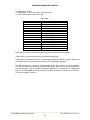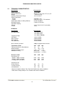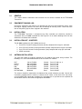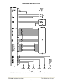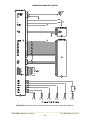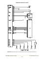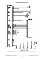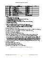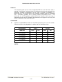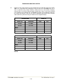
1
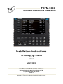
TDFM-9000
MULTIBAND P25 AIRBORNE TRANSCEIVER
Installation Instructions
TiL Document No. 11RE442
Rev. B
Issue 5
JULY 2013
Technisonic Industries Limited
240 Traders Boulevard, Mississauga, Ontario L4Z 1W7
Tel: (905) 890-2113 Fax: (905) 890-5338
www.til.ca
Copyright by Technisonic Industries Limited. All rights reserved.
TECHNISONIC INDUSTRIES LIMITED
REVISION HISTORY
[ 11RE442 ]
REV
SECTION
- PAGE -
DATE
EDITED
BY
A
2-5
Corrected Pin Numbers in Descriptions.
Mar 2013
SM
B
iv
Corrected DO-160 Version and Categories.
July 2013
SM
B–1
i
Updated TDFM-9000 Photo.
Aug 2013
SM
B–2
2-7 to 2-10
Figures 2.2 – 2.5 Corrected.
Oct. 28, 2013
AL
B–3
2-1
All
P/N in Section 2.4 Corrected.
Corrected Spelling & Grammar throughout
document.
Jan. 27, 2014
AL
B–4
iv
Changed STC Approval Note.
May 12, 2014
AL
Nov. 28, 2014
AL
1-2
1-2 and 2-7
B–5
DESCRIPTION
Added Special Order Band Codes.
Specified “Section 2.17 Configuration Menu”
Refers to TDFM-9000 Operating Instructions.
2-3
Added Antenna & Connector Locations as well as
Band Display Orientation.
All
Changed Format for Section Headers.
i
Corrected Issue Date.
TDFM-9000 Installation Instructions
TiL 11RE442 Rev. B Issue 5
ii
TECHNISONIC INDUSTRIES LIMITED
NOTES
ESD CAUTION
This unit contains static sensitive devices. Wear a grounded wrist strap and/or conductive gloves
when handling printed circuit boards.
FCC COMPLIANCE INFORMATION
This device complies with Part 15 of the FCC Rules. Operation is subject to the following two conditions:
(1) this device may not cause harmful interference and (2) this device must accept any interference
received, including interference that may cause undesired operation.
WARNING: For compliance with FCC RF Exposure Requirements the mobile transmitter
antenna installation shall comply with the following two conditions:
1. The transmitter antenna gain shall not exceed 3 dBi.
2. The transmitter antenna is required to be located outside of a vehicle and kept at a separation distance of 70
cm or more between the transmitter antenna of this device and persons during operation.
NOTE: This equipment has been tested and found to comply with the limits for a Class A digital device,
pursuant to Part 15 of the FCC Rules. These limits are designed to provide reasonable protection against
harmful interference when the equipment is operated in a commercial environment. This equipment
generates, uses, and can radiate radio frequency energy and, if not installed and used in accordance with
the instruction manual, may cause harmful interference to radio communications. Operation of this
equipment in a residential area is likely to cause harmful interference, in which case the user will be
required to correct the interference at his/her own expense.
WARNING AND DISCLAIMER
Changes or modifications not expressly approved by Technisonic Industries could void the user’s
authority to operate the equipment.
This manual is designed to provide information about the TDFM-9000. Every effort has been made to
make this manual as complete and accurate as possible.
WARRANTY INFORMATION
The Model TDFM-9000 Transceiver is under warranty for one year from date of purchase. Failed units
caused by defective parts or workmanship should be returned to:
Technisonic Industries Limited
240 Traders Boulevard
Mississauga, Ontario L4Z 1W7
Tel: (905) 890-2113
Fax: (905) 890-5338
TDFM-9000 Installation Instructions
TiL 11RE442 Rev. B Issue 5
iii
TECHNISONIC INDUSTRIES LIMITED
SUMMARY OF DO-160G ENVIRONMENTAL TESTING
Summary of DO-160G Environmental Testing for Technisonic Model TDFM-9000 Transceiver:
Conditions
Category
Temperature and Altitude
A2, B1, C4, D1
Temperature Variation
B
Humidity
A
Operational Shock and Crash Safety
A
Vibration
S, U
Magnetic Effect
Z
Power Input
B
Voltage Spike
B
Audio Frequency Susceptibility
B
Induced Signal Susceptibility
AC
Radio Frequency Susceptibility
T
Radio Frequency Emission
M
Electrostatic Discharge
A
INSTALLATION APPROVAL NOTE
Presently, no TSO standard exists for airborne FM transceivers. To make it easier for installation
agencies to provide their customers with an approved installation supported by an effective Airworthiness
Approval, Technisonic has secured Supplemental Type Certificate (STC) approval. The above referenced
DO-160G test data is also on file and available from Technisonic to support approval requirements in
airframes for which Technisonic does not possess an STC.
Approved aircraft types are listed in the attachments to the formal STC documents. These STCs are the
exclusive property of Technisonic and require the written authority of Technisonic for their use. To assist
Factory Authorized Technisonic Dealers in the certification process, we have placed copies of our
Canadian and US STCs on our website along with a letter of authorization for their use. These documents
may be downloaded and used as support for the technical submission to FAA or Transport Canada. Only
authorized factory dealers/installers are permitted to download and make use of these documents on
behalf of their customers (end users) in support of regulatory agency approval. Please refer to the
Technisonic website www.til.ca for the latest issue of available STCs and letter of authorization for use.
Trademark Notices
TDFM-9000 Transceivers contain two-way radio protocols licensed from Motorola, Inc.
© 1997, 1998 Motorola, Inc.
Motorola KVL 3000+® is a registered trademark of Motorola.
TDFM-9000 Installation Instructions
TiL 11RE442 Rev. B Issue 5
iv
TECHNISONIC INDUSTRIES LIMITED
TABLE OF CONTENTS
SECTION
SECTION 1
1.1
1.2
1.3
1.4
TITLE
PAGE
GENERAL DESCRIPTION B
INTRODUCTION .....................................................................................................................
DESCRIPTION ........................................................................................................................
MODEL VARIATION ...............................................................................................................
TECHNICAL CHARACTERISTICS .........................................................................................
1-1
1-1
1-1
1-3
SECTION 2 INSTALLATION INSTRUCTIONS B
2.1
2.2
2.3
2.4
2.5
2.6
2.7
2.8
2.9
2.10
2.11
2.12
2.13
2.14
2.15
2.16
2.17
2.18
2.19
2.20
2.21
2.22
GENERAL ...............................................................................................................................
EQUIPMENT PACKING LOG .................................................................................................
INSTALLATION .......................................................................................................................
INSTALLATION KIT – CONTENTS ........................................................................................
ANTENNA INSTALLATION ....................................................................................................
INSTALLATION – PIN LOCATIONS AND CONNECTIONS ..................................................
INSTALLATION – WIRING INSTRUCTIONS .........................................................................
MAIN GROUND – J1 PINS 1 AND 14 ....................................................................................
MAIN POWER + 28VDC – J1 PINS 2 AND 15 .......................................................................
MIC 1, 2, 3, 5, 6, AND 4 – J1 PINS 3, 6, 9, 19, 22, AND J6 PIN 6...........................................
MIC COMBINED 1 AND 2 – J6 PINS 7 AND 13 ....................................................................
AUDIO 1, 2, 3, 5, 6, AND 4 – J1 PINS 4, 7, 10, 20, 23, AND J6 PIN 5 ...................................
AUDIO COMBINED 1 AND 2 – J6 PINS 2 AND 10 ................................................................
PTT 1, 2, 3, 5, 6, AND 4 – J1 PINS 5, 8, 11, 21, 24, AND J6 PIN 3 .......................................
PTT COMBINED 1 AND 2 – J6 PINS 4 AND 12......................................................................
TX DATA AND RX DATA – J1 PINS 12 AND 13 .....................................................................
UP AND DOWN – J1 PINS 16 AND 17 ...................................................................................
CHANNEL/BAND – J1 PIN 18 .................................................................................................
PANEL BACKLIGHTING – J1 PIN 25......................................................................................
SPEAKER LO AND HI – J6 PINS 8 AND 9..............................................................................
ANTENNA SELECTION AND INSTALLATION CONSIDERATIONS......................................
POST INSTALLATION EMI TEST ..........................................................................................
2-1
2-1
2-1
2-1
2-1
2-4
2-6
2-6
2-6
2-6
2-6
2-6
2-6
2-7
2-7
2-7
2-7
2-7
2-7
2-7
2-13
2-13
APPENDIX A Support Notes ................................................................................................................ 2-24
WARRANTY ......................................................................................................................................... 2-25
TDFM-9000 Installation Instructions
TiL 11RE442 Rev. B Issue 5
v
TECHNISONIC INDUSTRIES LIMITED
LIST OF FIGURES
FIGURE
2.1
2.2
2.3
2.4
2.5
2.6
2.7
2.8
TITLE
PAGE
Outline Drawing ........................................................................................................................
TDFM-9000 Antenna & Connector Locations ..........................................................................
TDFM-9000 Band Display Orientation .....................................................................................
Wiring Connections for Individual Band Control with Separate Ground Returns .....................
Wiring Connections for Individual Band Control with a Single Ground Return ........................
Wiring Connections for Combined Band Control with Separate Ground Returns ....................
Wiring Connections for Combined Band Control with a Single Ground Return .......................
Wiring Connection Notes for the TDFM-9000 Transceiver ......................................................
2-2
2-3
2-3
2-8
2-9
2-10
2-11
2-12
LIST OF TABLES
TABLE
2.1
2.2
2.3
TITLE
PAGE
J1 25 Pin D Connections .......................................................................................................... 2-3
J6 15 Pin High Density D Connections .................................................................................... 2-4
J5 15 Pin High Density D Connections .................................................................................... 2-4
TDFM-9000 Installation Instructions
TiL 11RE442 Rev. B Issue 5
vi
TECHNISONIC INDUSTRIES LIMITED
SECTION 1: GENERAL DESCRIPTION
1.1
INTRODUCTION
This publication provides operating information on the TDFM-9000 airborne transceiver. The
exact configuration depends on which and how many RF modules are installed.
1.2
DESCRIPTION
The TDFM-9000 transceiver is an airborne multi-band radio capable of operation in conventional
analog and P25 digital FM systems, SmartNet/SmartZone trunking systems, and P25 9600
trunking systems. RF modules are available in single or dual bands that support VHF, UHF-LO,
UHF-HI, and 700-800 MHz bands. Up to 6 single or dual band modules can be supported.
These optional additional features include P25 9600 trunking Phase 1 and 2 that may be
combined with AES and/or DES-OFB encryption with OTAR in any of the available modules.
The TDFM-9000 is not normally frequency agile. In order to have the ability to change the
frequencies at the front panel, the FPP (front panel programming) option must be ordered for
each band. FPP is only available on the VHF and UHF modules.
1.3
MODEL VARIATION
There are several variations of the Model TDFM-9000 Transceiver. Each variation offers different
features and performance based on the type of RF modules and options installed.
RF Modules are mounted in trays of two (with up to 3 trays supported).
The following is a breakdown of the TDFM-9000 model variations:
P/N 101263-D-90-TBB-TBB-TBB-P9XXXX
(PRODUCT TYPE)-(D)-(9X)-(Tray 1)-(Tray2)-(Tray3)-(Project)
PRODUCT TYPE:
101263 = TDFM-9000 series, 3 trays, 2 – 6 modules
D= Display type:
1)
2)
Color TFT
Standard Green/NV
9X = TDFM-9000 series variant:
90 = TDFM-9000
TDFM-9000 Installation Instructions
TiL 11RE442 Rev. B Issue 5
1-1
TECHNISONIC INDUSTRIES LIMITED
Tray Breakdown: (TBB):
T= Module type: A= T30xx RF modules (Single or Dual)
B is Band code for each module in the tray.
Band Codes
1
2
3
4
A
B
C
D
E
F
*G
*H
*I
*J
*K
*L
VHF (136-174)
UHF LO (380-470)
UHF HI (450-520)
700/800 (764-870)
V/700/800
V/UHF LO
V/UHF HI
UL/UH
UL/700/800
UH/700/800
700/800/V
700/800/UL
700/800/UH
UHF LO/V
UHF HI/V
UH/UL
Band numbers indicate single band modules and letters indicate dual band modules.
* Band codes are special order and are not standard configuration.
Project Number: P9XXXX represents a 5-digit project number that identifies specific options that
are contained in each module and describes the full TDFM-9000 configuration.
All model variations are capable of supporting both 28 Volt and 5 Volt AC or DC back lighting.
The units are shipped set to operate on 28 Volt back lighting. Equipment can be set to operate on
5V back lighting by using the software based configuration menu. See Section 2.17 Configuration
Menu in the TDFM-9000 Operating Instructions available at www.til.ca. Damage will not occur if
the incorrect voltage is applied.
TDFM-9000 Installation Instructions
TiL 11RE442 Rev. B Issue 5
1-2
TECHNISONIC INDUSTRIES LIMITED
1.4
TECHNICAL CHARACTERISTICS
Specification
Characteristic
Model Designation:
Physical Dimensions:
Weight:
Operating Temperature Range:
Power Requirement:
Voltage:
Current:
Audio Output Power (including sidetone):
Microphone Inputs:
Panel Back Lighting:
Voltage:
Current:
TDFM-9000
Approx. (L) 8.0" x (W) 5.75" x (H) 4.5"
~7.0 Lbs (3.2 Kg)
-30° C to +60° C
28.0 VDC ± 15%
500 mA minimum / 7.5A maximum
65 mW into 600 Ω
Carbon or Equivalent
28 or 5 Volts AC or DC (selectable)
10 uA
RF Modules
Specification
Characteristic
RF Output Power:
1 or 6 Watts (VHF)
1 or 5 Watts (UHF)
1 or 3 Watts (700/800)
Frequency Range
VHF Band:
UHF LO Band:
UHF HI Band:
700 / 800 Bands:
136 to 174 MHz
380 to 470 MHz
450 to 520 MHz
764 to 870 MHz
No. of channels per band:
2000 pre-programmable channels
Transmitter section
FM Hum and noise in dB (wideband):
Audio Distortion:
Frequency Stability in ppm:
Modulation Limiting:
VHF
UHF
-48
-45
1%
1.0%
± 1.0 ± 1.0
Wide band
Narrow band
800
-45
1.0%
± 1.5
± 5 kHz
± 2.5 kHz
Receiver section
Sensitivity in uV:
* Digital 1% BER (12.5 kHz)
* Digital 5% BER (12.5 kHz)
** Analog with 12 dB SINAD
VHF
UHF
800
0.29
0.21
0.25
0.32
0.28
0.25
0.40
0.30
0.25
Selectivity in dB:
25 kHz Channel
12.5 kHz Channel
Intermodulation * **
-80
-70
-80
-78
-68
-80
-72
-67
-80
* Measured in digital mode per TIA / EIA IS 102.CAAA under nominal conditions.
** Measured in analog mode per TIA / EIA 603 under nominal conditions.
TDFM-9000 Installation Instructions
TiL 11RE442 Rev. B Issue 5
1-3
TECHNISONIC INDUSTRIES LIMITED
SECTION 2: INSTALLATION INSTRUCTIONS
2.1
GENERAL
This section contains information and instructions for the correct installation of the TDFM-9000
Transceiver.
2.2
EQUIPMENT PACKING LOG
Unpack the equipment and check for any damage that may have occurred during transit. Save
the original shipping container for returns due to damage or warranty claims. Check that each
item on the packing slip has been shipped in the container.
2.3
INSTALLATION
The TDFM-9000 Transceiver is designed to be Dzus mounted and should be installed in
conjunction with an IN-9000 installation kit. See Figure 2.1 for an outline drawing of the unit with
dimensions to facilitate the installation.
2.4
INSTALLATION KIT - CONTENTS
The IN-9000 installation kit (P/N 129292) consists of:
1. One 25 Pin Cannon D mating connector (female) complete with crimp pins and hood.
2. One 15 Pin HD Cannon D mating connector (female) complete with crimp pins and hood.
3. One 15 Pin HD Cannon D mating connector (male) complete with crimp pins and hood.
4. 6 BNC connectors.
2.5
ANTENNA INSTALLATION
The type and number of antennas depends on the model of transceiver being installed. The
following is a list of recommended antennas for the various RF modules:
VHF
UHFLO
UHFHI
800
800/700
VHF/UHF/800
136 to 174 MHz
403 to 470 MHz
450 to 520 MHz
800 to 870 MHz
764 to 870 MHz
Multiband
Comant
Comant
Comant
Comant
Comant
Rami
Part # CI-292-3 or -4
Part # CI-275
Part # CI-285
Part # CI-306
Part # CI-285
Part # AV-925
The antenna should be mounted on the bottom of the aircraft whenever possible. Consult with
instructions provided with the antenna. Connect the RF cables to the back of the transceiver
using the MALE BNC connectors provided in the installation kit. It is possible to use equivalent 50
ohm aviation antennas that cover the appropriate bandwidths.
TDFM-9000 Installation Instructions
TiL 11RE442 Rev. B Issue 5
2-1
TECHNISONIC INDUSTRIES LIMITED
FIGURE 2.1 Outline Drawing for Model TDFM-9000
TDFM-9000 Installation Instructions
TiL 11RE442 Rev. B Issue 5
2-2
TECHNISONIC INDUSTRIES LIMITED
ANT 5
ANT 6
ANT 1
ANT 2
J1
J5
ANT 4
J6
ANT 3
Figure 2.2 TDFM-9000 Antenna & Connector Locations
BANDS
1
2
3
4
5
6
Figure 2.3 TDFM-9000 Band Display Orientation
Band display corresponds to the antenna connector numbering and radio ports. Band 1 (top of
the display) is connected the ANT 1 and uses the Band 1 connections on the interface
connectors.
TDFM-9000 Installation Instructions
TiL 11RE442 Rev. B Issue 5
2-3
TECHNISONIC INDUSTRIES LIMITED
2.6
INSTALLATION - PIN LOCATIONS AND CONNECTIONS
J1 (25 Pin D Connections) - Use FEMALE Connector
Pin #
Description
1
2
3
4
5
6
7
8
9
10
11
12
13
14
15
16
17
18
19
20
21
22
23
24
25
Ground
Main Power +28 VDC
Mic 1
Audio 1
PTT 1
Mic 2
Audio 2
PTT 2
Mic 3
Audio 3
PTT 3
TX Data
RX Data
Ground
Main Power +28 VDC
Up
Down
Channel / Band
Mic 5
Audio 5
PTT 5
Mic 6
Audio 6
PTT 6
Panel Backlighting
TABLE 2.1 J1 (25 Pin D) Connections
TDFM-9000 Installation Instructions
TiL 11RE442 Rev. B Issue 5
2-4
TECHNISONIC INDUSTRIES LIMITED
J6 (15 Pin High Density D Connections) – Use FEMALE Connector
Pin #
Description
1
2
3
4
5
6
7
8
9
10
11
12
13
14
15
Ground
Audio Combined 1
PTT4
PTT Combined 1
Audio 4
Mic 4
Mic Combined 1
Speaker Lo
Speaker Hi
Audio Combined 2
Misc In
PTT Combined 2
Mic Combined 2
Misc In/Out
Audio Combined Ground 2
TABLE 2.2 J6 (15 Pin HDD) Connections
J5 (15 Pin High Density D Connections) – Use MALE Connector
Pin #
Description
1
2
3
4
5
6
7
8
9
10
11
12
13
14
15
Audio 2
Audio 5
Audio 6
Audio 3
Audio 4
Audio Ground 2
Audio Ground 5
Audio Ground 6
Audio Ground 3
Audio Ground 4
Audio 1
Audio Ground 1
Ground
Audio Combined Ground 1
Audio Combined 1
TABLE 2.3 J5 (15 Pin HDD) Connections
TDFM-9000 Installation Instructions
TiL 11RE442 Rev. B Issue 5
2-5
TECHNISONIC INDUSTRIES LIMITED
2.7
INSTALLATION - WIRING INSTRUCTIONS
Figure 2-2(a, b, and c) show all required connections and recommended wire sizes for the TDFM9000 transceiver. The TDFM-9000 allows for either a single audio output ground or separate
grounds for each audio output. If a single point ground is required for a pre-existing installation,
the dongle supplied in the installation kit must be plugged into J5. If this is a new installation, it is
recommended to use the isolated ground returns to the audio panel for reduced cross talk
between bands and airframe noise. The audio panel must have isolated grounds for each audio
input (such as Technisonic’s A710, A711, A711L, and TDAP-711) to take advantage of this
feature. There are receive audio, mic audio, and Push To Talk (PTT) lines for each band as well
as two sets of lines combining all six bands. The TDFM-9000 can be wired such that band
selection can be made on the audio panel. Up to 6 positions need to be available on the audio
panel; otherwise, the TDFM-9000 can be wired into one or two positions of the audio panel where
band selection and audio monitoring is done on the TDFM-9000 front panel. An installation can
be wired in a combination of both methods since all inputs and outputs are always active.
2.8
MAIN GROUND – J1 PINS 1 AND 14
Both pins should be connected to power ground. These pins are internally connected to the
chassis.
2.9
MAIN POWER + 28VDC – J1 PINS 2 AND 15
Both pins should be connected to +28 volts DC ± 15%.
2.10
MIC 1, 2, 3, 5, 6, AND 4 – J1 PINS 3, 6, 9, 19, 22, AND J6 PIN 6
The microphone input signals shall be connected using shielded wire with the shield connected to
ground (pin 1 or 14). For best results, it is recommended to leave the other end of the shield
floating to prevent ground currents unless you are connecting to an audio panel with floating hi
and lo inputs (like the Technisonic A710, A711, A711L, or TDAP-711) in which case the shield
must be connected to the lo input. These are individual inputs for each band.
2.11
MIC COMBINED 1 AND 2 – J6 PINS 7 AND 13
The combined mic inputs should be wired and shielded like the individual mic inputs above.
These mic inputs can be used for any band. Band selection is made at the TDFM-9000 front
panel.
2.12
AUDIO 1, 2, 3, 5, 6, AND 4 – J1 PINS 4, 7, 10, 20, 23, AND J6 PIN 5
These are individual audio outputs from each band. All outputs are 600 ohms impedance. The
output power is 65 mW maximum. Unused outputs do not have to be terminated and should be
left unconnected. These outputs are also found on J5 along with their respective grounds such
that a separate wire bundle can be run with only audio outputs, further reducing the possibility of
cross talk.
2.13
AUDIO COMBINED 1 AND 2 – J6 PINS 2 AND 10
These are combined audio outputs from all bands as selected from the front panel. The
specifications are the same as the individual outputs above.
TDFM-9000 Installation Instructions
TiL 11RE442 Rev. B Issue 5
2-6
TECHNISONIC INDUSTRIES LIMITED
2.14
PTT 1, 2, 3, 5, 6, AND 4 – J1 PINS 5, 8, 11, 21, 24, AND J6 PIN 3
There are individual PTT lines for each band. These lines should be floating when in receive and
grounded for transmit. The input has a pull up resistor to 5 volts. Connecting an audio panel that
wishes to see more may result in no receive audio. Connect a 1N4006 diode in series with the
cathode towards the audio panel in this case.
2.15
PTT COMBINED 1 AND 2 – J6 PINS 4 AND 12
These are combined PTT inputs to all bands as selected from the front panel. The specifications
are the same as the individual inputs above.
2.16
TX DATA AND RX DATA – J1 PINS 12 AND 13
These pins provide RS-232 serial communications for use with the RC-9000 remote control head
if installed. Consult the RC-9000 installation manual for details.
2.17
UP AND DOWN – J1 PINS 16 AND 17
These pins can be used to scroll up and down through the bands or channels for the band
currently selected depending on the band input below. The inputs normally floating are grounded
to activate. Two push buttons or a center off, SPDT, spring-loaded toggle switch are typically
used on these inputs.
2.18
CHANNEL/BAND – J1 PIN 18
The Channel / Band input determines the function of the up down inputs above. If left
unconnected, the inputs are for channel selection. If grounded, the input is for band selection.
2.19
PANEL BACKLIGHTING – J1 PIN 25
Connect to aircraft panel dimming bus. The transceiver is capable of supporting 28 VAC/DC or 5
VAC/DC backlighting circuits. Select 28 volts or 5 volts via the configuration menu (see Section
2.17 of the TDFM-9000 Operating Instructions). No damage will occur if the wrong setting is
made.
2.20
SPEAKER LO AND HI – J6 PINS 8 AND 9
Not normally connected in the aircraft. This output is 4 / 8 ohms at 1.1 watts max and has the
audio associated with Audio Combined 1. This output does not have to be terminated when not
used and should be left unconnected.
TDFM-9000 Installation Instructions
TiL 11RE442 Rev. B Issue 5
2-7
TECHNISONIC INDUSTRIES LIMITED
FIGURE 2.4 Wiring Connections for Individual Band Control with Separate Ground Returns
TDFM-9000 Installation Instructions
TiL 11RE442 Rev. B Issue 5
2-8
TECHNISONIC INDUSTRIES LIMITED
FIGURE 2.5 Wiring Connections for Individual Band Control with a Single Ground Return
TDFM-9000 Installation Instructions
TiL 11RE442 Rev. B Issue 5
2-9
TECHNISONIC INDUSTRIES LIMITED
FIGURE 2.6 Wiring Connections for Combined Band Control with Separate Ground Returns
TDFM-9000 Installation Instructions
TiL 11RE442 Rev. B Issue 5
2-10
TECHNISONIC INDUSTRIES LIMITED
FIGURE 2.7 Wiring Connections for Combined Band Control with a Single Ground Return
TDFM-9000 Installation Instructions
TiL 11RE442 Rev. B Issue 5
2-11
TECHNISONIC INDUSTRIES LIMITED
FIGURE 2.8 Wiring Connection Notes for the TDFM-9000 Transceiver
TDFM-9000 Installation Instructions
TiL 11RE442 Rev. B Issue 5
2-12
TECHNISONIC INDUSTRIES LIMITED
2.21
ANTENNA SELECTION AND INSTALLATION CONSIDERATIONS
Antenna installations will vary according to the number / type of bands installed in the TDFM9000, types of antennas selected, and space available on the aircraft. The materials list above
contains many but not all antennas available. If dual band RF modules are installed in the TDFM9000, it is suggested to use a single connector, multiband antenna for each of the RF modules
installed. When single band modules are installed, a single band antenna should be used. If the
TDFM-9000 has more than one single band module installed that are on different frequency
bands, a single multiband antenna with separate connectors or a multiband antenna with a
coupler can be used if the frequencies in use are not multiples of each other. For example,
transmitting near 150 MHz on VHF may interfere with frequencies near 450 MHz on the UHF
band. Antennas should be spaced as far as possible from each other with the Comm antennas on
the opposite side (top or bottom) from the FM antennas. See Technisonic’s Transceiver
Installation Guide and Antenna Selection Guide for more details.
2.22
POST INSTALLATION EMI TEST
PURPOSE
The purpose of this test is to identify any interference that the TDFM-9000 transceiver
may cause with existing aircraft systems.
TEST CONDITIONS
The TDFM-9000 transceiver should be installed and function tested. The antenna VSWR
should be checked. A forward/reverse power check with an in-line wattmeter should show
no more than 10% reflected power. For the following tests, ensure that the output power
is set to high.
METHODOLOGY
Most of the EMI tests can be accomplished on the ground. In some cases, flight testing is
required or is easier. If the aircraft is approved for IFR operations, then it is mandatory
that interference between the TDFM-9000 transceiver and the approach aids be checked
in flight.
The GPS should be operational and navigating with at least the minimum compliment of
satellites. The VHF comm should be set to the frequencies indicated with the squelch
open. VOR/DME receivers should be set to the frequencies indicated and selected for
display. If possible, set up a DME ramp test set on the frequencies indicated and adjust
the output until the flags are out of view. The transponder and encoder should be
monitored with ramp test equipment. Set the output of the transponder test set to 3db
above the output necessary to achieve 90% reply. If possible, set the ADF to a nearby
navigation station.
Modulate the TDFM-9000 transmitter on the indicated frequencies for at least 20 seconds.
Observe the GPS for any degradation in satellite status or availability or flags. Listen for
any noise or detected audio signals on the VHF comm(s). Listen for any noise or detected
audio signals on the VOR/LOC receiver audio; look for any moment of flags or needles on
the VOR/LOC/GS navigation display(s). Observe the transponder for any loss of reply or
spurious reply.
List the power plant, fuel, and other electric instruments in the chart provided and note
any anomalies that occur while transmitting. Assess the results.
If the aircraft is equipped with an autopilot or a stability augmentation system, then test fly
the aircraft and verify that operation of the TDFM-9000 transceiver does not have adverse
effects on these systems. After checking for gross effects at a safe altitude, fly an
approach with each of the different navigation systems coupled to the autopilot (ILS,
GPS, etc.) and look for any anomalies.
TDFM-9000 Installation Instructions
TiL 11RE442 Rev. B Issue 5
2-13
TECHNISONIC INDUSTRIES LIMITED
RESULTS
If the installed system passes all of the applicable EMI tests, then no further action is
required. If interference is observed, then the interference must be assessed against the
appropriate standards of airworthiness for the system in question. For example, it is
permissible for a VFR certified GPS to lose navigation capability while the TDFM-9000
unit is transmitting, providing that it recovers properly and promptly, but it is not
permissible for an IFR Approach certified GPS to be affected in the same way. A
complete discussion of all the standards of airworthiness to be applied in assessing EMI
effects is beyond the scope of this document.
PROCEDURE
A.
Operate the TDFM-9000 transmitter on the following frequency for at least 20 seconds.
Observe the GPS for any degradation in satellite status or availability or flags.
FREQUENCIES
TDFM-9000
GPS #1
PASS
GPS #2
FAIL
PASS
FAIL
143.2125 MHz
143.2250 MHz
157.5375 MHz
157.5500 MHz
512.0000 MHz
NOTES:
TDFM-9000 Installation Instructions
TiL 11RE442 Rev. B Issue 5
2-14
TECHNISONIC INDUSTRIES LIMITED
B.
Determine if the image frequency for the VHF Comm falls within the range of the TDFM9000. If so, select a set of frequencies that will cause the TDFM-9000 to be set as close
as possible to the image frequency. Any one of the many possible sets will suffice.
Record those values in the spaces provided in the following chart. Modulate the TDFM9000 transmitter on the following frequencies for at least 20 seconds. Listen for any noise
or detected audio signals on the VHF comm.
Example - Bendix/King KY 196A:
The first IF frequency is 11.4 MHz. The L.O. is above the received frequency (high side
injection); therefore, the image frequency is 22.8 MHz above the selected frequency. Set
the KY 196A to 120.000 MHz and the TDFM-9000 to 142.8000 MHz.
FREQUENCIES
RESULTS
VHF #1
TDFM-9000
135.975
136.0000
121.150
157.5000
131.250
157.5000
PASS
FAIL
Image:
FREQUENCIES
RESULTS
VHF #2
TDFM-9000
135.975
136.0000
121.150
157.5000
131.250
157.5000
PASS
FAIL
Image:
NOTES:
TDFM-9000 Installation Instructions
TiL 11RE442 Rev. B Issue 5
2-15
TECHNISONIC INDUSTRIES LIMITED
C.
Determine if the image frequency for the VOR/ILS Nav falls within the range of the TDFM9000. If so, select two sets of frequencies that will cause the TDFM-9000 to be set as
close as possible to the image frequency. Choose one set in the localizer frequency
range and one in the VOR frequency range. Record those values in the spaces provided
in the following chart. Modulate the TDFM-9000 transmitter on the following frequencies
for at least 20 seconds. Listen for any noise or detected audio signals on the receiver
audio; look for any moment of flags or needles on the navigation display.
FREQUENCIES
RESULTS
VOR/ILS #1
TDFM-9000
108.000
162.0000
108.100
162.1500
PASS
FAIL
Image:
FREQUENCIES
RESULTS
VOR/ILS #2
TDFM-9000
108.000
162.0000
108.100
162.1500
PASS
FAIL
Image:
NOTES:
TDFM-9000 Installation Instructions
TiL 11RE442 Rev. B Issue 5
2-16
TECHNISONIC INDUSTRIES LIMITED
D.
The following procedure checks for second harmonic interference to the glide slope
receiver from the TDFM-9000. All transceivers produce harmonics (multiples of the
wanted frequency) and while the TDFM-9000 far exceeds FCC requirements, interference
can still be experienced depending upon antenna position and separation. Furthermore,
other equipment in the aircraft and the structure of the aircraft can generate harmonics
where dissimilar metals make contact or where grounds are isolated, etc. This is also true
of aircraft hangars; therefore, testing should be done outside away from any structures
where possible.
With a portable glide slope generator, provide enough signal to firmly activate the
indicator needle and hide all flags. Increase the signal level by 3 dB. Modulate the TDFM9000 transmitter on the following frequencies for at least 20 seconds. Observe the Glide
Slope displays. Look for any movement of flags or needles on the navigation display. If an
interference condition is detected, then the installation will have to be flight tested
according to the following procedure. Using the table below, determine the glide slope
frequency based on the localizer frequency of the ILS to be used. Divide the glide slope
frequency by 2 and program into the TDFM-9000. Fly the aircraft to intercept the localizer
and glide slope (both needles centered) at 26 nm from the runway. Transmit on the
TDFM-9000 for 10 seconds and watch for any deflections or flags. Repeat the test every
2 nm until the indicators are not affected. If the distance is greater than 18 nm, then a
pass shall be recorded. Otherwise the TDFM-9000 shall be placarded “Do not transmit
while on ILS approach.”
Localizer
Glide slope
Localizer
Glide slope
108.10
108.15
108.30
108.35
108.50
108.55
108.70
108.75
108.90
108.95
109.10
109.15
109.30
109.35
109.50
109.55
109.70
109.75
109.90
109.95
334.70
334.55
334.10
333.95
329.90
329.75
330.50
330.35
329.30
329.15
331.40
331.25
332.00
331.85
332.60
332.35
333.20
333.05
333.80
333.65
110.10
110.15
110.30
110.35
110.50
110.55
110.70
110.75
110.90
110.95
111.10
111.15
111.30
111.35
111.50
111.55
111.70
111.75
111.90
111.95
334.40
334.25
335.00
334.85
329.60
329.45
330.20
330.05
330.80
330.65
331.70
331.55
332.30
332.15
332.90
332.75
333.50
333.35
331.10
330.95
TDFM-9000 Installation Instructions
TiL 11RE442 Rev. B Issue 5
2-17
TECHNISONIC INDUSTRIES LIMITED
FREQUENCIES
RESULTS
G/S #1
TDFM-9000
334.7 (108.1)
167.35
PASS
FREQUENCIES
FAIL
RESULTS
G/S #2
TDFM-9000
334.7 (108.1)
167.35
PASS
FAIL
NOTES:
E.
Operate the TDFM-9000 transmitter on the following frequency for at least 20 seconds.
Observe the Transponder for any spurious replies or loss of reply to test set.
FREQUENCIES
TDFM-9000
TRANSPONDER #1
PASS
FAIL
TRANSPONDER #2
PASS
FAIL
512 MHz
NOTES:
TDFM-9000 Installation Instructions
TiL 11RE442 Rev. B Issue 5
2-18
TECHNISONIC INDUSTRIES LIMITED
F.
Modulate the TDFM-9000 transmitter on the following frequencies for at least 20 seconds.
Observe the DME displays. Look for loss of distance information on the display.
FREQUENCIES
RESULTS
DME 1
TDFM-9000
978 (108.0)
489
1020 (112.1)
510
FREQUENCIES
PASS
FAIL
RESULTS
DME 2
TDFM-9000
978 (108.0)
489
1020 (112.1)
510
PASS
FAIL
NOTES:
TDFM-9000 Installation Instructions
TiL 11RE442 Rev. B Issue 5
2-19
TECHNISONIC INDUSTRIES LIMITED
G.
NOTE: For the following tests, select a frequency at the top, middle, and bottom of each
band of the TDFM-9000 transceiver.
136 to 174 MHz
Band
403 to 470 MHz
Band
450 to 512 MHz
Band
806 to 870 MHz
Band
Frequency #1
Frequency #2
Frequency #3
H.
At a safe altitude, engage the autopilot or stability augmentation system. Modulate the
TDFM-9000 transmitter on the above frequencies for at least 20 seconds. Observe any
effect on the autopilot or stability augmentation system.
Observations:
I.
Perform a coupled ILS approach to the aircraft's certified limits. Modulate the TDFM-9000
transmitter on the above frequencies for at least 20 seconds. Observe any effect on the
autopilot. Repeat for second flight director/autopilot if equipped.
Observations:
TDFM-9000 Installation Instructions
TiL 11RE442 Rev. B Issue 5
2-20
TECHNISONIC INDUSTRIES LIMITED
List the power plant, fuel and other electric instruments in the chart provided and note any
anomalies that occur while transmitting. Assess the results.
J.
STEP
1
SYSTEM
PASS
FAIL
NOTES
Com 1 & 2
(UHF Lo, UHF Hi, and 800 MHz)
2
Transponder & Encoder
(VHF, UHF Lo, and 800 MHz)
3
ADF 1 & 2
4
VG
5
Glideslope 1 & 2
(UHF Lo, UHF Hi, and 800 MHz)
6
VOR/LOC 1 & 2
(UHF Lo, UHF Hi, and 800 MHz)
7
Compass
8
Directional Gyro
9
Fuel Pressure
10
Oil Temp
11
Amps
12
Bus Voltage
TDFM-9000 Installation Instructions
TiL 11RE442 Rev. B Issue 5
2-21
TECHNISONIC INDUSTRIES LIMITED
13
Fuel %
14
Ng
15
TOT
16
Torque %
17
Annunciators
18
Digital Clock
19
Oil Pressure
20
DME 1 & 2
(VHF, UHF Lo, and 800 MHz)
21
GPS 1 & 2
(UHF Lo and 800 MHz)
TDFM-9000 Installation Instructions
TiL 11RE442 Rev. B Issue 5
2-22
TECHNISONIC INDUSTRIES LIMITED
STEP
SYSTEM
PASS
FAIL
NOTES
NOTES:
TDFM-9000 Installation Instructions
TiL 11RE442 Rev. B Issue 5
2-23
TECHNISONIC INDUSTRIES LIMITED
APPENDIX A
SUPPORT NOTES
•
For the latest Service Bulletin(s) refer to the Publication Index list under the section for this model
(login required).
•
For the latest Technical Information Bulletins refer to the Publication Index list under the section
for this model (login required).
•
For the latest Software Release(s) refer to the Publication Index list under the section for this
model’s software/firmware history index (login required).
NOTES
TDFM-9000 Installation Instructions
TiL 11RE442 Rev. B Issue 5
2-24
TECHNISONIC INDUSTRIES LIMITED
Technisonic Industries Limited
240 Traders Blvd., Mississauga, ON Canada L4Z 1W7
Tel: (905) 890-2113 Fax: (905) 890-5338
IMPORTANT
WARRANTY
All communication equipment manufactured by Technisonic Industries Limited is
warranted to be free of defects in Material or Workmanship under normal use for a period
of one year from Date of Purchase by the end user.
Warranty will only apply to equipment installed by a factory approved and/or authorized
facility in accordance with Technisonic published installation instructions. Equipment
falling under the following is not covered by warranty:
•
•
•
•
Equipment that has been repaired or altered in any way as to affect performance
Equipment that has been subject to improper installation
Equipment that has been used for purposes other than intended
Equipment that has been involved in any accident, fire, flood, immersion, or subject to
any other abuse.
Expressly excluded from this warranty are changes or charges relating to the removal and
re-installation of equipment from the aircraft. Technisonic will repair or replace (at
Technisonic's discretion) any defective transceiver (or part thereof) found to be faulty
during the Warranty Period.
Faulty equipment must be returned to Technisonic (or its authorized Warranty Depot) with
transportation charges prepaid. Repaired (or replacement) equipment will be returned to
the customer with collect freight charges. If the failure of a transceiver occurs within the
first 30 days of service, Technisonic will return the repaired or replacement equipment
prepaid.
Technisonic reserves the right to make changes in design, or additions to, or
improvements in its products without obligation to install such additions and
improvements in equipment previously manufactured. This Warranty is in lieu of any and
all other warranties express or implied, including any warranty of merchantability or
fitness, and of all other obligations or liabilities on the part of Technisonic.
This Warranty shall not be transferable or assignable to any other persons, firms, or
corporations.
For warranty registration, please complete the on-line
Warranty Registration Form found at www.til.ca.
TDFM-9000 Installation Instructions
TiL 11RE442 Rev. B Issue 5
2-25