1
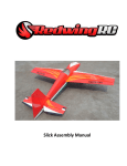
50cc EXTRA 260 ARF-QB
(Quick Build)
ASSEMBLY MANUAL
AEROWORKS
401 Laredo Unit “D”, Aurora, CO. 80011 - Phone 303-366-4205 - Fax 303-366-4203
E-mail - [email protected]
1
TABLE OF CONTENTS
Page
Aeroworks Contact Information ………………………………………………………………. 3
Introduction ……………………………………………………………………………………... 4
Kit Contents……………………………………………………………………………………… 5
Items Needed To Complete ……………………………………………………………………... 7
Tightening and Re-shrinking The Covering ………………………………………………….. 8
Check Seams and Overlaps for Good Seal ……………………………………………………. 9
Applying clear covering to the leading edges of wings and stabs ……………………………. 10
Wing Assembly………………………………………………………………….……………….. 13
Stab and Elevator Assembly……………………………………………………………………. 17
Rudder and Tail wheel Assembly ……………………………………………………………...
21
Main Landing Gear Assembly ……..…………………………………………………………... 33
Engine, Throttle, Muffler, and Canister or Pipe Installation………………………………..
39
Ignition Installation ……………………………………………………………………………... 63
Fuel Tank Installation………………..………………………………………………………….. 64
Cowl Installation…………………………………………………………………………………. 71
Radio Installation ………………………………………………………………………………... 77
Preflight Preparation …………………………………………………………………………….. 81
Finishing / Decal installation …………………………………………………………………….. 84
Center of Gravity (C.G.) / Control Throws …………………………………………… 89
2
401 Laredo Unit D
Aurora, CO 80011
Phone: (303) 366-4205
Fax: (303) 366-4203
Website: www.aero-works.net
E-mail: [email protected]
Thank you for choosing the Aeroworks 50cc EXTRA 260 ARF-QB. We put great effort
into making this plane the best model you will ever build and fly. We have provided you
with the highest quality kit and performance possible. We wish you great success in the
assembly and flying of your new Aeroworks 50cc EXTRA 260 ARF-QB.
!WARNING!
An R/C aircraft is not a toy! If misused, it can cause serious bodily harm and property
damage. Fly only in open areas, and AMA (Academy of Model Aeronautics) approved
flying sites. Follow all manufacturer instructions included with your plane, radio,
servo’s, batteries and engine.
Aeroworks manufacturing guarantees this kit to be free from defects in both material
and workmanship at the date of purchase. This warranty does not cover any component
parts damaged by use or modification. In no case shall Aeroworks liability exceed the
original cost of the purchased kit. Further, Aeroworks reserves the right to change or
modify this warranty without notice.
In that Aeroworks has no control over the final assembly or materials used for final assembly, No liability shall be assumed nor accepted for any damage resulting from the
use by the user of the final user-assembled product. By the act of using the userassembled product, the user accepts all resulting liability.
We, as the kit manufacturer, have provided you with a top quality, thoroughly tested
kit and instructions, but ultimately the quality and fly ability of your finished model
depends on how you build it; therefore, we cannot in any way guarantee the performance of your completed model, and no representations are expresses or implied as to
the performance or safety of your completed model.
3
INTRODUCTION
Your new 50cc EXTRA 260 ARF-QB is a highly aerobatic airplane. It is capable of both precision and 3-D maneuvers. The aircraft builds easily, quickly, and precisely due to its state
of the art CAD design, LASER cut technology, and high quality included hardware. We hope
you enjoy building and flying your 50cc EXTRA 260 ARF-QB.
Great care has been taken in both the design and manufacturing of the 50cc EXTRA 260
ARF-QB to allow for the strongest and lightest construction possible. Only the highest quality materials from the covering, paint, wood and hardware have been used in the construction
of this model.
The 50cc EXTRA 260 ARF-QB has been individually hand built, covered and painted by
trained and experienced craftsmen with over 25 years of manufacturing experience. Using
CAD design, laser cut technology and jig-built assures accuracy in all stages of production.
The 50cc EXTRA 260 ARF-QB is designed for gas engines in the 50cc category. The DA50cc engine is shown in the assembly instructions. The aircraft was tested with the DA-50cc
and has outstanding performance. The final choice of engine is left up to the builder. A
computer radio is recommended to allow the pilot to take advantage of the full capabilities of
this aerobatic aircraft.
IMPORTANT Please read through this manual carefully, before starting the assembly of
your new 50cc EXTRA 260 ARF-QB . Inventory and inspect all parts and hardware for any
imperfections or damage. Notify Aeroworks immediately if there are missing or damaged parts.
INTENDED USE
This plane should not be regarded as a toy. This is an aerobatic plane and is recommended for pilots
who are beyond the trainer-stage and are comfortable with flying an aerobatic sport plane.
!READ!
WARRANTY
!READ!
It is important to notify Aeroworks of any damage or problems with the model within 30
days of receiving your airplane to be covered under warranty. If you wish to return this aircraft for any reason a 15% restock fee will be charged to the customer. In addition the customer is responsible for all return shipping cost and all prior shipping cost will not be refunded. Parts will be exchanged or replaced once the original item is returned at the owner’s
expense. If you have any problems, please contact Aeroworks.
Aeroworks cannot insure the skill of the modeler and can not influence the builder during the
construction or use of this aircraft, and therefore, will not be accountable for any property
damage, bodily injury or death caused by this aircraft.
Aeroworks cannot insure the skill of the modeler and can not influence the builder during the
construction or use of this aircraft, and therefore,
The purchaser/operator accepts all responsibility of any and all structural or
mechanical failures.
4
KIT CONTENTS
(4) #6 bonded washers for the mounting of the
Canopy
(2) pull-pull exit tubes for rudder cable installed
(1) Antenna Tube installed
(1) engine box hatch cover, installed
50cc Extra 260 ARF-QB
Materials List
Basic Aircraft Parts
Fuselage with pre-installed vertical fin – covered,
Pre-installed and fuel-proofed firewall, pre drilled
for tail wheel assembly.
(4) 8-32 blind nuts installed for main landing gear
(4) 4-40 blind nuts installed for the mounting the
stab.
(6) 4-40 blind nuts installed for the mounting of
cowling.
(1) Hatch cover for the landing gear installed by (2)
T2.6 x 16mm PWA screws (2) flat washers.
Canopy base—painted with (4) 4-40 blind nuts installed
(1) Tinted Canopy—glued on the canopy base and
painted, installed on the fuselage by (4) 4-40 x 14
mm hex style bolts
Left Wing with Aileron – covered: pre drilled for control
horn mounting
(1) 8-32 blind nuts installed for the wing mounting.
(2) locater pins installed, pre drilled for cotter pin
(6) pin point hinges installed and glued
(1) Aileron servo string installed
Right Wing with Aileron – covered: pre drilled for
control horn mounting
(1) 8-32 blind nuts installed for the wing mounting.
(2) locater pins glued, pre drilled for cotter pin
(6) pin point hinges installed and glued
(1) Aileron servo string installed
5
#6:
(2) 4-40 3” two end threaded pushrod with nuts for
ailerons
(2) 4-40 4” two end threaded pushrod with nuts for
elevators.
(2) 4-40 x250mmThreaded pushrod - throttle and choke.
(2) 4-40 solder coupler - throttle and choke
(2) 4-40 metal clevis - throttle and choke
(2) 4-40 ball links - throttle and choke
Horizontal Stabilizer with elevator assembly with (8)
pin point hinges (glued)---covered, pre-drilled for control
horns.
Rudder with (5) pin point hinges (not glued) – covered,
pre-drilled for control horns.
SUB ASSEMBLIES
#7:
(2) 1x1100mm plastic coated pull-pull steel cable.
(4) 4-40 Metal R/C links with metal clevises and nuts
(4) 3.5x5mm brass pull-pull swaging tubes
(6) AL double control horns
(24) T2.6x16mm Phillips head mounting screws
(elevators, ailerons)
(12) T2.6X12mm Phillips head mounting screws
(rudder)
#1:
(1) Fiberglass Cowling—painted with (6) screws holes
(6) 4-40 x 16mm hex style bolts for mounting cowling
(6) 3mm split lock washers for mounting cowling
(6) #6 bonded washers for mounting cowling.
#2:
(1) 4mm 7075 Aluminum Main Landing Gear -- painted
(2) 5mm AL Axle Bolts
(2) M8 lock nuts
(4) 5mm i.d. Wheel Collars with set-screws
(2) 85mm Dia. Main Wheels (Lite Type)
(4) 4-40 x 16mm hex style bolts for mounting wheel
pants
(4) 3mm flat washer for mounting wheel pants
(4) 3mm split ring lock washer for mounting wheel
pants
(4) 8-32 x 20mm hex head bolts for mounting main
landing gear
(4) flat washers for mounting main landing gear
(4) split ring lock washers for mounting main landing
gear.
#8:
(1) 750cc (25 oz) Gas Fuel Tank assembly
(1) 450cc (15 oz) Smoke Tank assembly
4’ large gas fuel line
#3:
(2) Wheel Pants—1 Left and 1 Right---Painted
(4) 4-40 blind nuts installed on the wheel pants, 2 per
side.
#9:
(2) Servo mounting plates (throttle and choke)
(3) Engine mounting template (DA50, 3W50 and
blank for universal mounting)
(2) 1.6x102x610mm balsa sheet - pipe tunnel
(1) Plywood canister - pipe support former
(2) Balsa F3 former sheeting - canister (3 pcs/set)
(4) 11 o.d. x 20mm silicon tube - canister/pipe
(1) Plywood cover for tunnel entrance with AW logo
(4) T2.6x10mm screws for tunnel cover mounting
(1) 160x70x6mm foam for the Fuel tank.
(2) 300x80x8mm foam for the receiver and battery
(1) 610x20mm Velcro strap
#4:
(1) AL Tail Wheel Assembly – Medium
#10:
(24) 6mm aluminum engine stand offs.
#5:
(1) 32mm o.d. Anodized Aluminum Tube for wing
(2) 12.5mm o.d. Anodized. Aluminum Tubes for stab
one front and one rear.
(2) 8-32x25mm Hex head bolts for wing mounting
(2) #8 bonded washer for wing mounting
(2) #8 flat washers for wing mounting
(2) #8 split ring lock washer for wing mounting
(4) Hair pin for wing security - attachment
(4) 4-40x16mm Hex head bolts for stab mounting
(4) 3mm flat washer and (4) 3mm split ring lock washer
for stab mounting
(4) #6 bonded washers for stab mounting
#11
(10) 4-40 ball links / ailerons - elevators - rudder
(4) Brass spacers
#12
(1) Covering - White (small patching or repair)
(1) Covering - Red (small patching or repair)
(1) Covering - Blue (small patching or repair)
(1) Transparent covering - sealing hinge gaps
(2) Transparent covering strip - sealing of wing and
stab leading edges
#13
(1) AW - Custom throw meter - measure control
deflection
6
ITEMS NEEDED TO COMPLETE
Hardware:
•
•
•
•
•
•
•
•
•
•
•
•
•
•
•
•
•
•
•
•
•
•
•
•
•
•
•
•
•
•
•
•
•
50 CC Gas engine and ignition
Pitts style muffler or header with canister
muffler or tuned pipe
Engine mounting bolts, lock nuts, and washers.
3 1/2” Spinner and propeller of choice
2 x aileron servos (min 180 in./oz. Torque,
Digital, Metal geared)
1 x rudder servo (min 180 in./oz. Torque,
Digital, Metal geared)
2 x elevator servos (min 180 in./oz. Torque,
Digital, Metal geared)
1 x throttle servo (Fast / Reliable)
1 x choke servo (Fast / Reliable) optional
Servo extensions 2 x 6,” 3 x 12,” 2 x 18” 2 x 36”
1 x 8 channel receiver ( PCM recommended)
1 x receiver battery (min 6.0 volt / 1700ma)
1 x ignition battery (min 4.8 volt / 1700ma)
2 x switches with charge jacks
Allen wrenches US and Metric.
Dremel cutting disc and sanding drum tool
Electric drill and selection of bits
Razor saw
Flat head screwdriver
Hobby heat gun
Hobby iron and covering sock
Masking tape
Modeling knife
Needle nose pliers or crimping tool
Paper towels
Pen, pencil or felt tipped marker
Phillips screwdriver
Rubbing alcohol
Ruler and tape measure
Scissors
T pins
Waxed paper
Wire Cutters
Adhesives:
Tools:
•
•
•
•
•
•
•
15-30 Minute epoxy
Blue Loctite
Epoxy mixing cups, mixing sticks, brushes
CA kicker (optional)
Thick, Thin and Medium CA
Rubbing alcohol
Wipes
WARNING
Some rubbing alcohols
may attack painted parts.
7
TIGHTENING AND RE-SHRINKING THE COVERING
1. Open your kit slowly and take care not to damage any parts of the kit. Remove all parts from
their plastic protective covers for inspection.
Before doing any assembly or installation of any
decals it is very important to re-shrink or retighten the already applied covering. Due to the
shipping process, heat and humidity changes
from different climates, the covering may become lose and wrinkle in the sun. If you take the
time to re-tighten the covering, you will be rewarded with a long lasting beautifully covered
model.
3. If bubbles persist, use a small pin to punch holes
in the bubble to relieve trapped air and reheat.
4. Use your heat gun with extreme caution. Take
care not to apply too much heat to one area for
long periods of time. This may cause the trim
colors to over shrink and pull away leaving unsightly gaps on the color lines. The trim stripes
are especially vulnerable to over shrinking.
2. Using your covering iron with a soft sock, gently
apply pressure and rub in the covering. If any
bubbles occur, your iron may be to hot. Reduce
heat and work slowly.
5. You model is covered with Ultracote covering.
In case of repairs, the colors are:
Midnight Blue
Silver
True Red
White
#885
#881
#866
#870
Tightening and re-shrinking the covering is a
never ending process and needs to be checked
after each flying secession.
8
CHECKING SEAMS AND COLOR OVERLAPS FOR GOOD SEAL
1.
Go over all seams and color overlaps with
your sealing iron.
3. This is an optional step but is recommended.
Cut strips of the supplied clear covering to fit
the hinge gaps. Use covering iron to seal the
clear covering snugly into the bottom of the
hinge lines as shown for air tight hinge seals.
Note: Even if your models covering has no
wrinkles out of the box it is still very important
to go over all seams and overlaps to make certain they are sealed securely. This is especially important at the leading edges of the
wings and stabs. We recommend checking the
covering after each flying session.
2.
Use your covering iron to ensure all edges,
seams, and color overlaps are securely sealed.
IMPORTANT:
It is the users responsibility to check the
covering seams and overlaps for security
and a good seal. Aeroworks is not responsible for failure of covering seams or
overlaps during flight.
This is a never ending process that
must be done after each flying
secession. Due to varying temperatures and humidity changes from
day to day the covering will
continue to loosen and must be
maintained.
9
Applying clear covering to the leading edge of wings and stabs.
1.
In order to complete this step you will need:
3. Seal the top and bottom of the leading edge
carefully to insure the covering is securely
attached to the wood underneath.
Clear covering, Covering Iron, Scissors,
Rubbing Alcohol, and Paper towel.
2. Clean the leading edge of each wing thoroughly
4. Lay out one of the pieces of covering next to the
leading edge of the wing in order to find the
correct length for it to be cut to.
with rubbing alcohol in order to insure a clean
surface for the covering to stick to.
Note: Wing pictured in the following steps may
be a different color and model. However, the
procedure for applying the clear covering to
your model will be the same.
10
5. Cut the covering even with the wing tip being
careful not to cut it to short.
7. Remove the clear backing from the covering.
Note: Do not skip this step. There is a backing to
the covering. Take time to remove this backing to
get the correct adhesion to the already applied
covering.
6.
Save the excess covering from both wings in
order to seal the leading edge of the horizontal
stabs later.
8. Begin by tacking the covering in place at the
wing root. Pay close attention to insure that the
covering is centered top and bottom on the leading edge of the wing.
11
9. Using the same method as step 8 tack the covering to the tip of the wing once again keeping it
centered on the leading edge.
10.
11. Clear covering is now fully applied.
Note: Clear covering is centered on trim
colors. Using the same method complete
the remaining wing and stabs
Once the covering has been tacked in place
work from the center out to secure the covering to the leading edge of the wing.
IMPORTANT
It is the users responsibility to check the
covering seams and overlaps for security
and a good seal. Aeroworks is not responsible for failure of covering seams or
overlaps during flight.
This is a never ending process that
must be done after each flying
secession. Due to varying temperatures and humidity changes from
day to day the covering will
continue to loosen and must be
maintained.
12
WING ASSEMBLY
Aileron Servo Installation
1.
3.
Attach the 18” extension to the servo lead and
secure with safety wire, string, tape, or other
method. Ensure the plugs will not come apart
from vibration or light tension.
4.
Fasten the pull string from the servo hole to
the male plug of the servo extension. Secure
with tape so that the strings pulls from the
front end of the plug. Taper the tape to
The ailerons have been pre-hinged and glued
to the wing panels and are ready for flight. No
other steps are necessary for hinging.
Note: We have supplied clear Ultracote for
sealing the hinge gaps. This is an optional step
but is recommended
2.
Layout the servo on the wing to test fit the installation and ensure servo lead is the correct
length.
Note: 180 in. oz. digital, metal geared servos
are recommended. Servo selection can be the
difference between a great flying model and a
model that will crash. Always use brand name
high quality servos.
avoid hang-ups inside the wing.
13
5.
Draw the 18” servo extension through the
wing and pull through the wing root rib.
7.
Remove servo and use a 1/16 bit to drill servo
mounting holes.
6.
Install servo in servo well with the output arm
toward the leading edge of the wing and mark
locations of servo mounting holes.
8.
Install servo with servo mounting screws.
14
9.
Aileron servo mounted in bottom of wing.
2.
Assemble the pushrod and control horn assembly as shown. The ball link goes between the
left and right sides of the control horn sides
and is secured with a nylon lock nut. Start
with the center hole in the control horn. The
ball link may be moved up or down for more
or less control throw. Brass spacer goes between servo arm and ball link.
Aileron Control Linkage Installation
3.
Place the control horns over the predrilled
mounting holes.
1.
Gather the aileron control linkage parts as
shown below. 1 pushrod, 2 ball link assemblies, 1 brass spacer, 1 left and 1 right side
control horn, and 6 2.6 x 16mm wood screws
for each wing panel.
15
4.
Use a drop of thick CA glue on each screw as
shown.
6. Tape the trailing edge of the aileron to the trailing edge of the wing in the neutral position.
Plug the servo into the receiver and turn radio
on. Ensure the servo trim and sub trim is centered. Adjust the length of the pushrod so that
the servo arm is parallel to the aileron hinge line
when it is placed on the servo output shaft.
Screw servo arm on the servo output shaft.
Note: On metal geared servos use Loctite for all
Servo arm mounting screws.
5.
Securely fasten the control horn to the aileron
with six wood screws as shown.
7.
Ensure the servo does not bind at either end
point at full deflection. A 1” servo arm is recommended for best results. A 1 1/4” servo
arm is required for full deflection of the aileron
55º bevel.
8.
Repeat all the above steps for the other wing.
16
STAB AND ELEVATOR ASSEMBLY
Elevator Servo Installation
3.
Layout the servo on the fuse to test fit the installation and ensure servo lead is the correct
length.
4.
Feed the servo extension through the elevator
mounting hole into the fuse toward the nose as
shown.
1. The elevators have been pre-hinged and glued to
the stabs and are ready for flight. No other steps
are necessary for hinging.
Note: We have supplied clear Ultracote for sealing the hinge gaps. This is an optional step but is
recommended
Gather the stabs and elevators, two elevators servos, and two 36” servo extensions as shown below.
2. Attach the 36” extension to the servo lead and
secure with safety wire, string, tape, or other
method. Ensure the plugs will not come apart
from vibration or light tension.
Note: 180 in. oz. digital, metal geared servos are
recommended. Servo selection can be the difference between a great flying model and a model
that will crash. Always use brand name high
quality servos.
17
5. Install servo in servo cut out with the output
shaft toward the nose and mark locations of
servo mounting holes.
6.
7.
Remove servo and use a 1/16 bit to drill servo
mounting holes.
Install servo with servo mounting screws.
Elevator Control Linkage Installation
1.
18
Gather the elevator control linkage parts as
shown below. There are 2 pushrods, 4 ball
link assemblies, 2 brass spacers, 2 left and 2
right side control horns, and 12 2.6 x 16mm
wood screws for each stab and elevator.
2.
Assemble two pushrod and control horn assemblies with servo output arms as shown.
The ball link goes between the left and right
sides of the control horn sides and is secured
with a nylon lock nut. Start with the center
hole in the control horn. The ball link may be
moved up or down for more or less control
throw. A 1 1/2” servo arm is recommended to
achieve full deflection of the elevator bevel.
3. Brass spacer goes between servo arm and ball
link
4.
Place the control horn over the pre-drilled
mounting holes as shown.
19
5.
Use a drop of thick CA glue on each screw as
shown.
6.
Mount the control horn using six wood screws
as shown.
7.
Tape leading edge of the elevator balance tab
to the leading edge of the stab in the neutral
position. Plug the elevator servo into the receiver and turn radio on. Ensure the servo
trim is centered.
8.
Attach the stab and elevator to the fuse and
screw in place. Adjust the length of the elevator pushrod so that the servo arm is 90 degrees
to the servo case when it is placed on the servo
output shaft. Ensure the servo does not bind
at either end point at full deflection.
9.
Repeat the above steps for the other stab and
elevator.
20
RUDDER AND TAILWHEEL ASSEMBLY
Rudder Installation
1.
Gather the rudder, four hinges, rubbing alcohol, petroleum jelly and epoxy materials as
shown. Use 15-30 minute epoxy to ensure adequate working and cleanup time.
2.
Prep all hinges for installation by applying
Vaseline petroleum jelly or light oil to the
hinge joint. This ensures no epoxy gets into
the hinge during assembly.
21
3.
Mix epoxy in mixing cup and use a tapered
stick to apply the epoxy inside the pre-drilled
holes in the trailing edge of the fin. Apply
epoxy to one side of each hinge and insert the
hinge completely into the hole. Ensure the
hinge axis is vertical and parallel to the trailing
edge of the fin before epoxy cures. Wipe
away excess epoxy with alcohol wetted wipes.
4.
Epoxy the hinges into the fin first and allow
epoxy to fully cure.
5.
6.
Mix epoxy in mixing cup and use a tapered
stick to apply the epoxy inside the pre-drilled
holes in the leading edge of the rudder. Apply
epoxy to trailing edge of each hinge.
7. Ensure there is no gap between fin and rudder.
Allow epoxy to fully cure.
Note: We have supplied clear Ultracote for sealing the hinge gaps. This is an optional step but is
recommended
Carefully slide the rudder onto each hinge and
against the trailing edge of the fin. Wipe away
excess epoxy with alcohol wetted wipes.
Rudder Servos Installation
1. Gather one rudder servo with double output arm
as shown below. Note: 180 in. oz. digital, metal
geared servo is recommended. Servo selection
can be the difference between a great flying
model and a model that will crash. Always use
brand name high quality servos.
22
2. Install the rudder servo in the forward servo cutout with the output shaft to the rear.
4.
Install rudder servo with servo screws.
Your model may only have one rudder servo
cut out. Only one rudder servo is required for
full rudder performance.
3.
Mark and use a 1/16 bit to drill the rudder
servo mounting holes.
Rudder Pull-Pull Cable Installation
1.
23
Gather the rudder control linkage parts shown
below. Rudder cable, 2 ball link assemblies,
2 threaded metal RC links, 4 threaded couplers, 4 brass swaging tubes, 2 left and 2 right
side control horns, and 12 2.6 x 12mm wood
screws.
2.
Gather the rudder control linkage parts shown
below. 2 Rudder cables, 2 threaded metal RC
links, 4 threaded couplers, and 4 brass swaging tubes.
4.
Pull the rudder cables from rear of fuse to the
rudder servo tray.
3.
Feed one rudder cable through the pre installed
cable exit tube in the rear of the fuse toward
the front of the fuse. Repeat for other side.
5.
Insert rudder cable through the brass swage
tube, then through the threaded coupler hole,
and back through the brass swage tube as
shown.
24
6.
Loop the cable back through the brass swage
tube as shown.
8.
If additional crimping is needed a small CClamp may be used for additional crimping
pressure.
7.
Tighten the second loop through the brass
swage tube and crimp the brass tube with a
crimping tool or pliers.
9.
Cut off excess cable as shown
25
10.
A drop of thin CA may be applied to the
swage tube to help secure the cable. Attach a
metal threaded RC link to the threaded coupler.
11.
Repeat above steps for the other side rudder
cable.
12.
Attach the RC links to the rudder servo arm
and then attach the servo arm to the rudder
servo as shown.
Rudder Control Horn Installation
26
1.
Gather the rudder control horn parts as shown
below. 2 ball link assemblies, 2 left and 2
right side control horns. Assemble the ball
links between the control horns as shown.
Secure with nylon lock nut. Start with the center hole in the control horn. The ball link may
be moved up or down for more or less control
throw.
2.
Place the control horns over the predrilled
mounting holes.
3.
Use a drop of thick CA glue on each screw as
shown.
6. Plug the rudder servo into the rudder channel of
the receiver and power up. Turn on transmitter
to center rudder servo. Ensure servo trim and
sub trims are centered.
Note: On metal geared servos use Loctite for all
Servo arm mounting screws.
4.
Mount rudder control horns using six wood
screws.
5.
Repeat the above steps for mounting the other
side rudder control horn.
7.
27
Tape the rudder balance tab to the top leading
edge of the vertical fin in the neutral position
as shown. This ensures the rudder is straight
when the cables are attached.
8.
Remove ball links from the rudder control
horns. Attach two threaded couplers to ball
links as shown. Thread couplers halfway into
ball links to allow for correct adjustment.
10.
Attach ball link to rudder control horn on both
sides of the rudder. Thread the rudder cable
through a brass swage tube, then the threaded
coupler, and back through the brass swage
tube on both sides. Pull light tension on the
cable through the coupler on both sides as
shown. The loop through the coupler should
be approximately 1/2” long.
9.
Hold the threaded coupler below the cable attach holes to thread into the ball link as shown.
Do not hold coupler at the top where the cable
hole is located. This may cause burrs on the
coupler that can eventually cut the rudder pull
cable.
11
Loop the cable back through the brass swage
tube as shown.
28
12.
Tighten the second loop through the brass
swage tube as shown.
14.
Cut off excess cable. A drop of thin CA may
be applied to the swage tube to help secure the
cable.
13.
Crimp the brass tube with a crimping tool or
pliers.
15.
Hold the threaded coupler below the cable attach holes to thread into the ball link as shown.
Do not hold coupler at the top where the cable
hole is located. This may cause burrs on the
coupler that can eventually cut the rudder pull
cable. Thread coupler in or out at ball link end
to achieve correct length to fit into rudder control horn..
29
16.
17.
Re-attach ball link to rudder control horn on
both sides of the rudder.
Tail Wheel Installation
With radio on, and rudder centered, adjust rudder pull-pull cables to desired tension by
screwing in or out on the threaded couplers
and or ball links. Make all adjustments with
the rudder servo still powered up. Ensure the
servo does not bind at center or at either end
point.
30
1.
Gather the tail wheel parts shown below.
Tail wheel strut and leaf spring, 3 tail wheel
mounting screws, steering tiller, 2 tiller
mounting screws, and 2 steering springs.
2.
Apply a drop of thick CA to the tiller arm
mounting screws before inserting in the
pre-drilled holes.
3.
Mount the tail wheel steering tiller using two
wood screws.
5.
Mount the tail wheel struts and leaf spring
using three wood screws.
4.
Place the tail wheel leaf spring on top of the
tail wheel strut. Position the tail wheel and
spring on the bottom of the fuse. Place a drop
of thick CA on tail wheel strut mounting
screws before inserting in the pre-drilled
mounting holes on the bottom rear of the fuse.
6.
Attach the steering springs on both sides of the
tail wheel to the rudder tiller and tail wheel
tiller. Center the springs between both tillers.
31
7.
Use pliers to twist spring ends closed around
the tillers after desired tension and direction
adjustments are complete.
8.
Tail wheel final assembly is complete.
32
MAIN LANDING GEAR ASSEMBLY
Main Landing Gear Installation
1.
Gather the landing gear parts as shown below.
Landing gear strut, 4 mounting bolts, washers,
and lock washers, 2 wheels, 2 axles, and 4
wheel collars as shown below.
2.
Gather the gear strut, 4 mounting bolts, washers, and lock washers, as shown below.
33
3.
Remove landing gear cover screws.
4.
After screws are removed, remove the landing
gear cover.
5.
Note that the trailing edge of the landing gear
strut is tapered. The tapered edge goes toward
the rear of the fuse.
7.
Bolt landing gear strut to fuse with 4 bolts,
lock washers and flat washers. Ensure tapered
edge of the gear strut is facing toward the rear.
6.
Use a drop of blue Loctite on landing gear
bolts before attaching the landing gear.
8.
Reinstall the gear cover.
34
9.
Use a drop of blue Loctite and reinstall the
landing gear cover screws.
Wheels and Wheel Pants Installation
1.
Gather the wheels, axles, and wheel collars as
shown below.
35
2.
Use a drop of blue Loctite on landing gear axle
bolt before attaching the landing gear axle
with the nylon lock nut.
3.
Use two wrenches to screw the lock nut on the
wheel axle. Do not tighten securely yet.
4.
Align the flat sides of the axle bolt vertical and
snug the lock nut against the landing gear
strut. Do not tighten securely yet. Then
align the wheel pant slot over the axle bolt as
shown below. Slide the wheel pant slot over
the flat sides of the axle bolt and align the
wheel pant with the wheel pant mounting
holes.
6.
Now tighten the axle nut against the landing
gear strut with a small wrench while using the
wheel pant slot to hold the flat sides of the
axle bolt in alignment. Tighten the lock nut
enough so that the axle bolt will not rotate during final tightening.
5. Install and tighten the wheel pant mounting bolts
to hold the wheel pant in place.
7.
Now remove the wheel pant mounting bolts.
Note: Do not use Loctite at this time.
36
8.
Remove the wheel pant.
10.
Install the inner wheel collar next to the axle
bolt. Using Loctite, tighten the inner wheel
collar in place.
9.
Use wrenches to permanently tighten the axle
to the gear strut.
11.
Install the wheel and outer wheel collar. Use
blue Loctite on the wheel collar set screw before final tightening.
37
12.
Slide the lock washer then the flat washer on
the wheel pant mounting bolts. Use blue Loctite on the bolts before final tightening.
13.
Install wheel pants with two mounting bolts
and Loctite.
14.
38
Repeat above steps for other wheel and wheel
pant.
ENGINE, THROTTLE, MUFFLER, CANISTER OR PIPE INSTALLATION
Engine Installation
3.
To modify mounting template to accommodate
your engine of choice.. Line up the template
with the engine thrust lines.
4.
Mark the location of the engine mounting
holes on template.
1. The 50cc EXTRA 260 will accept a wide range
of engine types. The DA-50 rear carburetor and
the 3W-55 rear and side carburetor engines with
Pitts style mufflers, canisters, and pipes were
mounted. Illustrations for each type of installation are provided below.
NOTE: Distance from front of firewall to
engine prop hub is 6 1/4” to 6 3/8”.
Depending on your engine selection. The
only difference will be the gap between the
cowling and spinner back plate.
2. Locate the laser cut engine mounting template
for either the DA-50 or 3W-55. If other engines
are used the templates may be modified for any
mounting pattern.
39
5.
Use a 1/4 drill to drill the engine mounting
holes.
7. It is recommended to center punch the location
of the engine mounting holes prior to drilling.
6.
Align the template with the firewall and mark
the location of the engine mounting holes.
8.
40
Use a 1/4 drill to drill the engine mounting
holes in firewall.
3.
Rear Carburetor Engine Installation
1.
If installing canister muffler or tuned pipe,
skip to canister installation on page 43
The following instructions are for a rear carburetor style engine with Pitts style muffler.
The DA-50 rear carburetor with 2 1/2” stand
offs is shown in the following steps.
Securely tighten the engine to the firewall as
shown. We recommend using 1/4-20 bolts and
lock nuts for engine mounting. You may also
use blind nuts behind the firewall for engine
mounting.
Note: The use of large fender washers is recommended between the spacers and firewall to
distribute loads. Washers are Not Supplied!
Note: 2 1/2” stand offs are supplied with the
DA 50.
2. Mount the engine using the engine manufacturer
recommended bolts (not supplied) and blue Loctite.
4. Typical rear carburetor engine installation
DA 50 with 2 1/2” stand offs is pictured below.
Use the provided aluminum spacers to make the
front of the engine prop hub (back of spinner)
approximately 6 1/4”to 6 3/8”inches from the
front of firewall.
DA-50 with 2 1/2” standoffs = 6 1/4”
3W-55i with 2 6mm standoffs = 6 3/8”
41
5.
6.
Use blue Loctite to install the Pitts muffler
bolts. Remember to always use the engine
manufacturer suggested gasket for proper seal.
7. DA-50 with Pitts style muffler mounted.
Securely tighten the muffler bolts to the engine.
8. 3W-55i-US with Pitts style muffler mounted.
3W-55i with 2 6mm standoffs = 6 3/8”
Note: 2 1/2” aluminum stand offs used with no
other stand offs required.
Note: Two 6mm aluminum spacers used at each
mounting bolt to archive proper engine stand off
from front of firewall. Aeroworks provided.
42
Pipe or Canister Muffler Installation
1.
2.
Canister Tunnel Preparation
The 50cc EXTRA 260 can accept either a
tuned pipe or canister muffler installation.
Gather the pipe or canister muffler parts as
shown below. 1 header, Teflon coupler, 2
clamps, pipe or canister, and supplied silicon
tubing and plywood mount.
The canister muffler installation will be illustrated first. If the canister muffler will be
used, gather the canister muffler parts shown
below.
43
1.
Iron the bottom covering to ensure it is tight
and well sealed to the wood.
2.
Use a hobby knife to remove the covering
from the bottom of the fuse between the two
formers and inside stringers as shown below.
3.
Bottom covering removed between the fuse
formers and stringers shown.
5. Insert the silicon tube insulators in the slots of
the wood canister holding bracket as shown.
Note: It may be necessary to cut the silicon tube into
4 separate pieces at 1” lengths.
4.
Gather the plywood canister holding bracket
and silicone tube insulators as shown.
6. Apply thick CA glue to the front of the canister
holding bracket where it will contact the front
former.
Note: It is recommended to test fit bracket prior to
gluing to ensure good fit.
44
7.
Inset the canister holding bracket against the
rear side of the front former and apply CA
glue to the top and bottom where it contacts
the fuse former and fuse floor.
9.
Gather the pre-cut balsa sheeting for closing
off the rear section of the canister tunnel.
8.
Canister holding bracket shown installed behind front former.
10.
Rear former shown where sheeting will be
installed.
45
11. Using thick CA, glue in place one half section of
balsa sheeting to the front side of rear former.
13.
Canister tunnel rear balsa sheeting shown installed. Glue in securely around all edges.
14.
Turn the fuse right side up. Run the elevator
and rudder servo wires through the small hole
in the former forward of the rudder servo as
shown.
Note: It is recommended to test fit balsa sheeting
prior to gluing to ensure good fit.
12. Glue in the other half section of balsa sheeting to
rear former.
Note: It is recommended to test fit balsa sheeting
prior to gluing to ensure good fit.
46
15.
Dry fit the top balsa sheeting to front side of
former and mark the location for the antenna
guide tube. Drill a 1/8” hole for the antenna
tube to pass through the balsa sheet. Using
thick CA, glue sheeting to front of former.
Canister and Header Installation
1. Assemble the canister to the header pipe with the
Teflon coupler and clamps in accordance with
manufactures instructions.
Note: It is easier to install the canister, header
assembly prior to installing the engine.
16.
Pass the antenna tube through guide hole and
press sheeting tight against former as shown.
Ensure the servo wires pass through the bottom notch as shown.
2.
47
Insert the canister into the tunnel and through
the canister holding bracket insulators.
3.
Canister and header inserted into the tunnel.
5.
Securely tighten the engine mounting bolts to
the firewall.
4.
Install engine, refer to pages 39-40 for engine
installation. Use blue Loctite on all engine
bolts.
6.
Use blue Loctite to secure header pipe bolts to
engine. Remember to always use the engine
manufacturer suggested gasket for proper seal
48
7.
Securely tighten header pipe bolts to engine.
9. Top view of the DA-50 and final canister
muffler installation.
Note: When top hatch is secured in place the
fuselage will be sealed for proper air flow.
Additional balsa sheeting can be applied to the
underside of the radio floors if desired. We
have also used Ultracote on the top side of the
radio floors to seal the lighting holes in
the fuselage.
8.
Bottom view of the DA-50 and final canister
muffler installation.
Tuned Pipe Tunnel Preparation
1.
49
If the tuned pipe will be used, gather the
header and tuned pipe parts as shown below.
1 header, coupler, 2 clamps, and tuned pipe
assembly.
2.
Iron the bottom covering to ensure it is tight
and well sealed to the wood.
4.
Use a hobby knife to remove the covering
from the inside edges between the middle and
front formers and bottom stringers in the pipe
tunnel opening.
3.
Use a hobby knife to remove the covering
from the inside edges between the middle and
rear formers and bottom stringers in the pipe
tunnel opening.
5.
Bottom covering removed from the inside
edges of the bottom pipe opening.
50
6. Gather the pipe holding bracket and silicone
tube insulators as shown.
8.
Ensure the elevator servo wires are routed
through the small holes in the former just behind the rudder servo.
9.
It will be necessary to lightly sand the tabs in
the former to get a good flush fit of the canister holding bracket against the fuselage former.
Note: It may be necessary to cut the silicon tube into
4 separate pieces at 1” lengths.
7.
Insert the silicon tube insulators in the slots of
the wood pipe holding bracket as shown.
51
10. Apply thick CA glue to the rear of the pipe
holding bracket where it will contact the front of
the fuselage former.
12.
Securely glue the pipe holding bracket to the
fuselage former.
13.
Canister holding bracket shown installed in
front of former.
Note: It is recommended to test fit bracket prior to
gluing to ensure good fit.
11. Insert the pipe holding bracket against the front
former and hold in place until glue dries.
Note: Holding bracket fits to top of former and
notches in holding bracket fit between bottom
stringers.
52
14.
15.
Use supplied Ultracote to recover the front
bottom pipe opening.
Tuned Pipe Installation
Rear bottom pipe opening is left open for pipe
stinger and air flow exit.
53
1.
Insert pipe into tunnel.
2.
Insert pipe through pipe holding bracket insulators as shown. Pipe stinger should exit
through the opening in the bottom of the fuse.
3.
Bottom view of the tuned pipe installation.
5.
Tuned pipe and header pipe inserted into the
tunnel.
4.
Assemble the tuned pipe to the header pipe
with the Teflon coupler and clamps in accordance with manufactures' instructions.
6.
Install engine, refer to engine installation on
pages 39-40. Use blue Loctite on engine bolts.
54
7. Top view of DA-50 and final tuned pipe installation.
Throttle Servo and Choke Installation
1.
Note: Additional balsa sheeting can be applied to the
underside of the radio floors to help with
proper air flow and exit. We have also used
Ultracote on the top side of the radio floors to
seal the lighting holes in the fuselage.
8.
Gather the left and right plywood throttle and
choke servo mounting trays, the throttle and
choke servos and pushrod parts as shown
below.
2 x 4-40 metal rods thread at one end
2 x 4-40 ball inks
2 x 4-40 threaded solder couplers
2 x 4-40 threaded quick links
3W-55 with tuned pipe and header installed.
2.
55
Use a 1/4” bit to drill a pushrod exit hole in the
firewall in line with the engine carburetor
throttle arm.
3.
It is recommended to remove the top engine
mounting hardware from the same side as your
throttle arm. This will make attaching the ball
link to your throttle arm much easier.
5.
Dry fit the servo tray to the fuselage. The
throttle servo is mounted on the side of the
fuse that aligns with the engine carburetor
throttle arm. Use the throttle pushrod to help
line up proper mounting position
Note: If properly lined up with hole in engine
box cover will allow easy access to servo arm
and servo mounting screws
6.
4. Temporally Attach the ball link to the throttle
pushrod and secure to the carburetor throttle arm
with a 4-40 bolt and nylon lock nut.
Note: Do not Loctite at this step
56
Drill throttle servo mounting holes and install
throttle servo to mounting tray.
7. With fuel tank temporarily laid in position trail
fit servo tray to fuselage. Ensure throttle servo
mounting tray does not interfere with fuel tank
installation.
9. Ensure the throttle servo and servo tray are in
the correct position to allow the throttle pushrod
to actuate the carburetor throttle arm with out
binding or rubbing against the hole in the firewall.
Note: If positioned properly you will be able to
access servo mounting screws through top
hatch and back of former.
8.
10.
Mark the location of the servo mounting tray
on the fuse side.
57
Mark the locations on the servo tray where the
fuse sides contact the servo tray to show where
to place the epoxy when gluing the tray inside
the fuse.
11.
Prepare to epoxy the servo mounting tray to
the fuse side. Remove the servo from the servo
tray to protect against getting any glue onto
the servo
13.
Install the servo mounting tray to the fuse side
aligned with the marks. Hold in place until the
epoxy cures.
12.
Apply epoxy to side of servo tray that will
contact the fuse side on the locations previously marked.
14.
Reinstall throttle servo to tray.
58
15.. Thread the quick link half way onto the
threaded coupler then install the quick link
onto the throttle servo arm. Position the throttle servo arm at center travel and the carburetor arm at center travel. With the quick link
attached to the throttle servo arm., mark the
location to cut the throttle pushrod to correct
length.
17.
16.
18. Using sand paper remove any paint from pushrod at location of solder joint. This will give you
a stronger solder joint. Place the threaded
coupler over the pushrod. Solder coupler to
throttle pushrod.
Remove ball link from throttle arm and remove the throttle pushrod.
Cut throttle push rod to correct length.
Note: It is recommended to use a good quality silver
solder for a secure solder joint.
59
19.
Attach the ball link to the throttle pushrod and
secure to the carburetor throttle arm with a
4-40 bolt and nylon lock nut.
21.
Ensure the throttle pushrod operates smoothly
and does not bind or rub against the hole in the
firewall.
22.
Reattach the engine mounting if previously
removed.
Note: Use Loctite to prevent ball link from
vibrating loose
20.
Attach quick link to throttle servo arm.
60
23.
1.
Front view of throttle pushrod installed.
2.
If a manual choke will be installed gather the
choke pushrod, ball link, wheel collar and nylon ties as shown. Wheel collar and ties are
not supplied.
Servo Actuated or Manual Choke
3.
We recommend installing the carburetor choke
pushrod as shown. Use nylon ties to provide
support and holding friction for the choke
pushrod. Place silicon fuel tubing over the
wire pushrod to prevent damage from vibration and provide holding friction. Place a
wheel collar on the end of the pushrod to provide a finger grip.
You can install a choke servo if desired. Use
the same mounting steps as the throttle servo
with the supplied hardware shown below.
61
4. Position the pushrod to allow easy access
through the front of the cowl air intake as
shown.
This is a easy, effective and light weight method for
operating the engine choke.
62
IGNITION INSTALLATION
Ignition Installation
1.
Gather the ignition and installation parts as
shown below.
2.
Position the engine ignition on the side of the
engine mounting box and mark the location of
the nylon tie holes as shown.
63
3.
Use a 1/8” drill bit to drill the ignition mounting holes.
4.
Mount the engine ignition module using nylon
ties and foam rubber as shown. Route the ignition wire to the engine as shown and secure
with nylon ties as necessary. Install the ignition battery and regulator if required as desired. A typical ignition installation is shown
below. Secure all wiring from excess vibration.
FUEL TANK INSTALLATION
3. Insert the rubber stopper into the tank with the
vent tube at the top of the tank. Secure the stopper with the screw as shown.
Fuel Tank Assembly
1. Gather the fuel tank parts as shown below. Fuel
tank and hardware, fuel tubing, foam rubber and
nylon ties.
Note: Take care not to over tighten screw and strip
rear metal stopper cap.
2. Place the rubber stopper between front and rear
metal stopper caps and insert the screw do not
tighten. Assemble the fuel pick up tube with
clunk and vent tube as shown into the stopper.
Secure both ends of the fuel pick up tube with
nylon ties as shown.
Note: It is highly recommended you solder a brass
barb to the end of the fuel pick up tube to prevent the
fuel line from coming loose due to the weight of the
fuel clunk. (brass barb not supplied)
4. After the tank is assembled, gather the parts as
shown below to install the tank inside the fuse.
Fuel tank, foam rubber, fuel line, fuel “ T “, fuel
filler dot and large nylon ties.
Note: Fuel “ T ” and fuel filler dot are not included.
64
3.
Fuel Tubing Installation
Cut the fuel line to the length required to attach to the carburetor fuel intake nipple.
1. Attach the fuel line to the fuel pick up tube on
the tank as shown.
Note: It is highly recommended you solder a brass
barb to the end of the fuel pick up tube to prevent the
fuel line from coming loose ( brass barb not supplied)
2.
Place the fuel tank inside the fuse as shown.
Run the fuel line forward through the firewall
hole toward the engine as shown.
4. Remove the tank and cut the fuel line just forward of the tank stopper as shown for preparation of installing fuel “ T “.
Note: Fuel “ T “ is not included.
65
5. Install the “ T “ fitting on the fuel line as shown.
Use a heat gun to very slightly heat and soften
the fuel tubing if necessary to insert the nipple.
7. Cut the fuel supply line just forward of the
“ T “ and install an inline fuel filter as shown.
Note: Fuel filter is not supplied
Note: Glass cleaner or soapy water can also be used
to help slide fuel line over fittings.
6.
Assemble the fuel supply line as shown below.
8. Gather the fuel filler dot parts as shown below.
Note: fuel filler dot is not supplied
66
9. Install the fuel filling dot as desired on the side
of the fuse.
11.
Install the fuel filler dot as shown. Place the
nylon washers on the outside and inside of the
fuse and secure with nut inside the fuse as
shown.
12.
Install the remaining fuel line on the remaining
nipple of the fuel “ T “ as shown.
Do not allow the fuel dot to interfere with the
leading edge of the wing.
Use a smaller size drill bit to drill the pilot hole for
the fuel dot.
10. Then using from small to larger sized drill bits
finish drilling the fuse side for the fuel dot.
Note: Starting with a small drill bit then gradually
going to a larger drill bit size will prevent the
fuse side from splitting.
67
13.
Place the fuel tank inside the fuse and run the
fill line through the fuel dot installed on the
fuse side as shown. Cut the line 2-3” outside
the fuse side to allow it to pull out for filling.
15.
Secure all fuel line joints with the small nylon
ties as shown. Trim away excess nylon ties.
14.
Remove the tank from the fuse. Install the
remaining fuel line to the vent tube on the tank
as shown. Locate the small nylon ties as
shown.
16.
The final tank assembly prior to installation
into the fuse.
68
Fuel Tank Installation
1.
Install two long nylon ties under the fuel tank
mounting floor as shown.
2.
Place the foam rubber pad on the fuel tank
mounting floor as shown
69
3.
Install the tank. Run the feed line to the engine
and the fill line out of the fuel filler dot as
shown. Secure the tank with the two long
nylon ties as shown. Trim away excess nylon
tie as shown.
4.
Install the fuel dot plug in the fill line and insert into the fuel dot in the fuse side as shown.
5.
Route the vent line on top of the fuel tank and
secure with small nylon ties as shown. This
will stop excess fuel from draining out the
vent line during an extended down line or
when lifting the tail.
6.
Drill a 1/4” hole in the bottom of the engine
box to allow the vent line to exit through the
bottom of the engine box as shown.
7.
70
Secure the vent line to the bottom of the front
former as shown.
COWL INSTALLATION
1.
Gather the following material for making a
cowl cutout template. Use a large envelope or
cardboard file folder for template material.
3.
Measure 3/8” from the edge of the template as
shown.
2.
Measure and mark the center of the template
as shown.
4.
Draw a line 3/8” from the edge of the template
as shown. This will allow for the overhang of
the cowling behind the front former.
71
5.
Mark the fuse centerline on the bottom of the
front former as shown.
7.
Ensure there is a 3/8” overlap behind the front
former as shown.
6.
Tape the template to the bottom of the fuse
3/8” back from the front former and on centerline as shown.
8.
Hold the template up to the exhaust stacks and
trace around the location of both of the exhaust stacks as shown.
72
9. Use a hobby knife to cut out the tracing around
both of the exhaust stacks as shown,
11.
Use a hobby knife to cut out the cylinder head
opening as shown.
12.
Pull up the template and ensure the cutouts
will clear the exhaust stacks and cylinder head
as shown. Trim as necessary to achieve approximately 1/8” to 1/4” clearance around the
cylinder head. Remove the template from fuse.
Note: This hole is only for allowing the template
to pull up to the cylinder head and will be
enlarged later for a cooling air exit.
10.
Pull up the template to the engine cylinder
head. Trace around the engine cylinder so that
they can extend below the template after the
tracing is cut out.
73
13.
Mark a centerline onto the bottom of the cowl
as shown.
15.
Tape the template to the cowl as shown.
14.
Align the paper template with the cowl as
shown. Ensure the center lines are aligned and
the 3/8”overlap line is on the aft edge of the
cowl.
16.
Draw a larger cooling air exit hole on the paper template that is aligned with the leading
edge of the exhaust stacks. Ensure all the holes
will have approximately 2-3 times the area as
the intake holes on the front of the cowl
74
17.
Use a hobby knife to cut out the cooling air
exit in the paper template as shown.
19.
Use a felt tip marker to transfer the template
cutout patterns to the cowl as shown. Ensure
all the holes will have approximately 2-3 times
the area as the intake holes on the front of the
cowl
18.
Cylinder head and cooling air exit cutouts
completed in paper template.
20.
Use a rotary tool disc cutting wheel to rough
cut the holes in the bottom of the cowl.
75
21.
Use a rotary tool drum sander to finish cut and
round out the corners from the rough cut.
22.
Final cuts should look similar to this in the
bottom of the cowl.
23.
76
Trial fit the cowl to the fuse and trim sand as
necessary to achieve approximately 1/8” to
1/4” clearance from all engine parts. Ensure
all the holes will have approximately 2-3 times
the area as the intake holes on the front of the
cowl
RADIO INSTALLATION
1.
Gather the switches and mounting hardware to
be used. We used two switches, one for receiver battery, and one for ignition battery, and
regulators for lithium ion batteries. The installation steps are similar for all types of
switches.
3.
Use a modeling knife to cut out the switch
holes.
2. Switch location is at the discretion of the
builder. We chose to place the switches toward
the front of the fuse on each side. Mark location
for switches using switch back mounting plate as
a template.
4.
Slide switch wires inside fuse through the
switch cutout.
Note: Make sure switch does not interfere with
leading edge of wing.
77
5.
Mount switches in accordance with the switch
instructions and hardware.
7.
Mount the radio components as desired using
the radio tray cutouts. Ensure all wires and
plugs are secure and not subject to chafing
when routed through the radio tray and formers.
6.
Gather the radio mounting hardware as shown
below. Foam rubber, Velcro straps, and nylon
ties.
8.
Typical installation of ignition batteries on
side of engine box using foam rubber base
and nylon ties.
78
9.
Ensure all radio plugs are secured with tape
and will not come loose under light tension
and vibration.
11. Slide the receiver antenna wire into the antenna
tube in the fuse as shown.
Note: Using talcum powder will help to slide
antenna through tubing.
10.
Typical installation of receiver battery and
regulator in fuse using Velcro and foam rubber
for battery and screws for the regulator.
12.
79
Secure the antenna wire to the tube with tape
to prevent it from sliding back out from engine
vibration as shown.
13.
Secure the receiver to the radio tray with foam
rubber base and nylon tie as shown.
14.
Typical RC installation viewed from top.
15.
80
Typical ignition installation viewed from the
top.
PRE-FLIGHT PREPARATION
1.
Gather (2) 8-32 wing mounting bolts, (2) #8
rubber backed washers and (4) hairpins for
preparation of mounting the wings.
3.
Install hairpins into both front and rear
aluminum anti-rotation wing dowels for a
second method of wing attachment.
2.
Slide the wing tube in the fuse wing tube
sleeve. Slide the wings on the wing tube and
plug in the aileron servo plugs. Slide the rubber backed washers on the wing mounting
bolts and insert bolts through the fuse side and
into the wing root blind nuts. Tighten snugly
but do not over tighten and crack the fuse or
wing root wood.
4.
Gather (4) 4-40 stab mounting bolts and (4)
#6 small rubber backed washers.
81
5.
Slide the stab tubes in the fuse stab tube
sleeves. Slide the stabs on the stab tubes and
plug in the elevator servo plugs. Slide the rubber backed washers on the stab mounting bolts
and insert bolts through the stab mounting tabs
and into the fuse blind nuts. Tighten snugly
but do not over tighten and crack the stab
mounting tabs or the fuse sides.
7.
Mount the cowl using the cowl mounting bolts
and rubber backed washers. The rubber backed
washers are to prevent the fiberglass cowl
from cracking and to prevent mounting bolts
from loosing from normal engine vibration.
6.
Gather (6) 4-40 cowl mounting bolts and (6)
#6 small rubber backed washers.
8.
Remove the tape holding in the canopy bulkhead hatch.
Note: Shown below are only (4) mounting bolts and
washers. You will use (6) mounting bolts and
washers for securing the cowl.
82
9. Remove the canopy bulkhead hatch as shown. If
desired an optional instrument panel and pilot
may be installed.
11. Gather the (4) 4-40 hatch mounting bolts and (4)
#6 small rubber backed washers.
Note: It is highly recommended you apply thin CA
glue to the front hold down dowels. This is a High
vibration area and can loosen the front dowels.
Note: Instrument panel and pilot are not supplied in
the kit but may be purchased separately from
Aeroworks.
Always check the front dowels are secure before
each flying session
Us thin CA to
secure front
hatch hold
down dowels
10. Reinstall the canopy frame hatch and glue in
place as shown. Use care not to get glue on the
clear plastic canopy.
12.
Note: Epoxy or thick CA glues are recommended.
83
Slide the rubber backed washers on the hatch
mounting bolts and insert bolts through the
hatch mounting holes and into the fuse blind
nuts. Tighten snugly but do not over tighten
and crush the hatch or the fuse sides.
FINISHING
DECAL INSTALLATION
3. Factory placement of decals shown.
Decal installation
1. Decals supplied with the kit may vary from the
photos below.
Gather supplied decals, transfer tape, ruler, scissors, hobby knife, plastic squeegee or credit
card, Windex or Application fluid like Rapid
Tac. Also, a solution of 1 drop of dish detergent
to a cup of water sprayed on the model will assist in proper positioning.
Note: clean surface and tighten all covering before
any decals are applied.
2. Factory placement of decals shown.
84
4. Factory placement of decals shown.
6.
5. Cut transfer tape to accommodate decal size.
Remove backing from Clear transfer tape.
7.
Note: Transfer tape will be reused. DO NOT throw
away any transfer tape until decal
placement is complete.
85
Apply clear transfer tape over top of
decal.
8. Press transfer tape to top of decal.
10.
9. Peel backing from decal.
11.
86
Spray model surface with application fluid,
Windex or soapy water solution.
Spray back side of decal with
application fluid, Windex or soapy
water solution.
12. Position decal in proper location. Application
fluid will allow decal to be moved slightly.
14.
Pull transfer tape from top of decal. Take
care not to pull away or damage decal.
13. Using a plastic squeegee or credit card. Spread
decal smooth and remove all excess application
fluid. Let decal set until dry enough to be able
to remove transfer tape with out removing
decal. Do not leave until completely dry or
transfer tape will be difficult to remove.
15.
Let decal dry before applying top decal.
87
16. Repeat installation process of bottom decal for
top decal installation. Use application fluid for
easier installation
18.
Pull transfer tape from top of decal. Take
care not to pull away or damage decal.
17. Place top decal over bottom decal. Position evenly
and centered on bottom decal. Press top decal onto
bottom decal and squeegee out excess application
fluid. Let decal dry until transfer tape can be lifted
without removing decal.
19.
Finished decal installation. Work slowly
and carefully and you will be rewarded
with a beautifully finished model.
88
CENTER OF GRAVITY - CONTROL THROWS
Center of Gravity
3” Back from wing L.E. at wing tip
3. Start at recommended CG until you are comfortable with the flight characteristics of the aircraft.
You may find this a bit nose heavy at first but
that is fine to start with. After you are comfortable adjust the CG to suit your flying style in
small steps, especially when shifting the CG toward the tail. Move the battery or add small
stick on weights to the nose or tail as necessary.
1. Warning, do not skip this step!
The recommended CG is 3” back from the
wing leading edge at the wing tip as shown.
4. For aerobatic flying a more aft balance point is
better. For smooth sport flying a more forward
CG is better. An aircraft that is too nose heavy
does not fly well and is difficult to land. A tail
heavy aircraft is uncontrollable and will likely
crash.
Control Throws
1. The amount of control throw should be adjusted
using mechanical means as much as possible and
then electronically with the radio. The control
throws are shown in degrees and inches of deflection measured at the widest point of the control surface for both low and high rates.
2. Balance the 50cc EXTRA 260 ARF-QB without
fuel in the tank with the batteries installed and
ready to fly. The engine, radio, servos, and battery you use will determine the final weight and
locations of equipment. Try to balance the
model by moving the battery and receiver before
adding any ballast.
.
2. Use the widest part of the aileron as shown to
measure the aileron throw in inches.
89
3.
Use the widest part of the elevator as shown to
measure the elevator throw in inches.
5. Use the supplied flight control deflection meter
to measure the throws in degrees. Prop up the
tail of the aircraft until the fuselage is
parallel to the table top.
4. Rudder throw measured in inches.
6.
Use the widest part of the elevator to
measure the elevator throw in degrees..
Hint: Taping a pencil or pen to the trailing edge
of the rudder will help you to see the correct
amount of rudder travel
7.
90
Location for throw meter to measure Aileron
throw in degrees.
Control Throw Deflection Table
Low Rate
Preflight Checks
Center of Gravity: Check CG is set properly.
High Rate
Aileron
2 1/2” or 25˚ up
3” or 30˚ up
2 1/2” or 25˚ down 3” or 30˚ down
Rudder
2 1/2” or 35˚ left
2 1/2” or 35˚ right
Engine: The engine should run smoothly at all
throttle settings with smooth transition from
idle to full throttle without stalling or hesitation. Do not fly an unreliable engine. Read
engine instructions including break in and tuning completely.
3 1/2” or 40˚ left
3 1/2” or 40˚ right
Elevator 1 3/8” or 12˚ up
2” or 18˚ up
1 5/8” or 16˚ down 2 1/4” or 24˚ down
Prop balancing: Ensure prop is properly balanced
prior to mounting on engine.
Flight Controls: Ensure all flight controls are
free from binding and are centered. Check
that all hinges are tight and will not pull out.
Control linkages must be rigid and tight and
have no slop. Confirm proper direction of ailerons, rudder, and elevator. Experienced flyers have lost airplanes due to reversed ailerons. Right roll is right up, left down. Left roll
is left up, right down.
For 3D flying use the following throws:
3D Rate
Aileron
3 1/2” or 35˚ up
3 1/2” or 35˚ down
Rudder
6” or 45˚ left
6” or 45˚ right
Batteries: Transmitter, ignition and receiver batteries are fully charged.
Elevator 4 1/2” or 45˚ up
4 1/2” or 45˚ down
Fasteners: Check all engine bolts, wing bolts,
hatch bolts, servo screws, control horn bolts,
wheel collars, and clevis keepers are tight and
secure.
We recommend 15% Expo on low rates, 30%
expo on high rates, and 60% expo on 3D rates as
a starting point. You a can adjust from there to
suit your own flying style.
Covering: Check all covering and seams are
sealed and secure.
Radio: Check trims set to neutral and controls
centered. Check rate and condition switches
set properly. Check the receiver antenna is
fully extended and not reversed on it self.
Range check: Do a range check with and without
the engine running in accordance with the radio manufacturer instructions. If there is insufficient range or a large reduction with the
engine running, do not fly until it is resolved!
Fuel: Fill the fuel tank before each flight.
91
Aerobatics
The 50cc EXTRA 260 ARF-QB is capable of any
aerobatic maneuver. After you gain some confidence and little experience flying the airplane you
can cut loose and perform any maneuver you can
think of. Here is a list of some of the more popular
aerobatic and 3D maneuvers you can try:
•
•
•
•
•
•
•
•
•
•
•
•
Loops and rolls
Knife edge flight
Stall turns
Snap rolls
2, 4, and 8 point rolls
Slow rolls
Spins upright and inverted
Flat Spins upright and inverted
Harriers upright and inverted
Water falls
Torque Rolls
Rolling circles
The sky and your imagination are you only limits.
FLY and ENJOY!
AEROWORKS
92
50 cc EXTRA 260 ARF-QB NOTES
___________________________________________________________________________
___________________________________________________________________________
___________________________________________________________________________
___________________________________________________________________________
___________________________________________________________________________
___________________________________________________________________________
___________________________________________________________________________
___________________________________________________________________________
___________________________________________________________________________
___________________________________________________________________________
___________________________________________________________________________
___________________________________________________________________________
___________________________________________________________________________
___________________________________________________________________________
___________________________________________________________________________
___________________________________________________________________________
___________________________________________________________________________
___________________________________________________________________________
___________________________________________________________________________
___________________________________________________________________________
__________________________________________________________________________
93