1
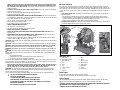
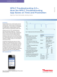
INSTRUCTION MANUAL
D28710-XE
HEAVY-DUTY 355 mm (14") CHOP SAW
• SECURE THE WORKPIECE. Use clamps or a vise to hold the workpiece on the table and against the fence
or when your hand will be dangerously close to the blade (within 6"). It is safer than using your hand and it
frees both hands to operate tool.
• DON’T OVERREACH. Keep proper footing and balance at all times. Loss of balance may cause personal
injury.
• MAINTAIN TOOLS WITH CARE. Keep tools sharp and clean for best and safest performance. Follow
instructions for lubricating and changing accessories. Poorly maintained tools and machines can further
damage the tool or machine and/or cause injury.
• TURN THE MACHINE “OFF”, AND DISCONNECT THE MACHINE FROM THE POWER SOURCE before
installing or removing accessories, before adjusting or changing set-ups, when making repairs or changing
locations. An accidental start-up can cause injury. Do not touch the plug’s metal prongs when unplugging or
plugging in the cord.
• REDUCE THE RISK OF UNINTENTIONAL STARTING. Make sure that the switch is in the “OFF” position
before plugging in the power cord.
• USE PROPER EXTENSION CORD. Make sure your extension cord is in good condition. If your product is
equipped with a cordset, use only 3-wire extension cords that have 3-prong grounding-type plugs and 3-pole
receptacles that accept the tool’s plug. When using an extension cord, be sure to use one heavy enough to
carry the current your product will draw. An undersized cord will cause a drop in line voltage resulting in loss
of power and overheating. The following table shows the correct size to use depending on cord length and
nameplate ampere rating. If in doubt, use the next heavier gage. The smaller the gage number, the heavier the
cord.
MINIMUM GAUGE FOR CORD SETS
For Cable length (m):
7.5
15
25
30
45
60
Use Cable with minimum rating (Amperes)
Tool Amperes
0 - 3.4
7.5
7.5
7.5
7.5
7.5
7.5
3.5 - 5.0
7.5
7.5
7.5
7.5
10
15
5.1 - 7.0
10
10
10
10
15
15
7.1 - 12.0
15
15
15
15
20
20
12.1 - 20.0
20
20
20
20
25
–
• CHECK FOR DAMAGED PARTS. Before further use of the tool, a guard or other part that is damaged should
be carefully checked to determine that it will operate properly and perform its intended function—check for
alignment of moving parts, binding of moving parts, breakage of parts, mounting and any other conditions
that may affect its operation. A guard or other part that is damaged should be properly repaired or replaced.
Do not use tool if switch does not turn it on and off.
• USE RECOMMENDED ACCESSORIES. Use only accessories that are recommended by the manufacturer for
your model. Accessories that may be suitable for one tool may be hazardous when used on another tool.
Consult the instruction manual for recommended accessories. The use of improper accessories may cause
risk of injury to persons.
• NEVER STAND ON TOOL. Serious injury could occur if the tool is tipped or if the cutting tool is unintentionally
contacted.
• NEVER LEAVE TOOL RUNNING UNATTENDED. TURN POWER OFF. Don’t leave tool until it comes to a
complete stop. Serious injury can result.
• DO NOT OPERATE ELECTRIC TOOLS NEAR FLAMMABLE LIQUIDS OR IN GASEOUS OR EXPLOSIVE
ATMOSPHERES. Motors in these tools may spark and ignite fumes.
• STAY ALERT, WATCH WHAT YOU ARE DOING, AND USE COMMON SENSE. DO NOT USE THE MACHINE
WHEN YOU ARE TIRED OR UNDER THE INFLUENCE OF DRUGS or ALCOHOL. A moment of inattention while
operating power tools may result in injury.
Definitions: Safety Guidelines
The definitions below describe the level of severity for each signal word. Please read the manual
and pay attention to these symbols.
DANGER: Indicates an imminently hazardous situation which, if not avoided, will result in death
or serious injury.
WARNING: Indicates a potentially hazardous situation which, if not avoided, could result in death
or serious injury.
CAUTION: Indicates a potentially hazardous situation which, if not avoided, may result in minor
or moderate injury.
NOTICE: indicates a practice not related to personal injury which, if not avoided, may result in
property damage.
IF YOU HAVE ANY QUESTIONS OR COMMENTS ABOUT THIS OR ANY DEWALT TOOL, CALL US AT: 1800 444 224
(Aust) or 0800 339 258 (NZ).
Important Safety Instructions
WARNING: Read all instructions before operating product. Failure to follow all instructions listed below
may result in electric shock, fire and/or serious injury.
READ ALL INSTRUCTIONS
Double Insulation
Double insulated tools are constructed throughout with two separate layers of electrical insulation or one double
thickness of insulation between you and the tool’s electrical system. Tools built with this insulation system are not
intended to be grounded.
NOTE: Double insulation does not take the place of normal safety precautions when operating this tool. The
insulation system is for added protection against injury resulting from a possible electrical insulation failure within
the tool.
CAUTION: WHEN SERVICING USE ONLY IDENTICAL REPLACEMENT PARTS. Repair or replace damaged cords.
Safety Instructions For All Tools
This miter saw accepts the DEWALT worklight and laser attachments.
WARNING: To reduce the risk of eye injury, ALWAYS use eye protection when operating the miter saw.
• KEEP GUARD IN PLACE and in working order.
• REMOVE ADJUSTING KEYS AND WRENCHES. Form habit of checking to see that keys and adjusting
wrenches are removed from spindle before turning tool on. Tools, scrap pieces, and other debris can be
thrown at high speed, causing injury.
• KEEP WORK AREA CLEAN. Cluttered areas and benches invite accidents.
• DO NOT USE THE MACHINE IN A DANGEROUS ENVIRONMENT. The use of power tools in damp or wet
locations or in rain can cause shock or electrocution. Keep your work area well-lit to avoid tripping or placing
arms, hands, and fingers in danger.
• KEEP CHILDREN AWAY. All visitors should be kept at a safe distance from work area. Your shop is a
potentially dangerous environment.
• MAKE WORKSHOP CHILDPROOF with padlocks, master switches, or by removing starter keys. The
unauthorized start-up of a machine by a child or visitor may result in injury.
• DON’T FORCE TOOL. It will do the job better and be safer at the rate for which it was designed.
• USE RIGHT TOOL. Don’t force tool or attachment to do a job for which it was not designed. Using the
incorrect tool or attachment may result in personal injury.
• WEAR PROPER APPAREL. No loose clothing, gloves, neckties, rings, bracelets, or other jewelry to get
caught in moving parts. Non-slip footwear is recommended. Wear protective hair covering to contain long
hair. Air vents may cover moving parts and should also be avoided.
• ALWAYS USE SAFETY GLASSES. Everyday eyeglasses are NOT safety glasses. Also use face or dust mask
if cutting operation is dusty. ALWAYS WEAR CERTIFIED SAFETY EQUIPMENT:
• ANSI Z87.1 eye protection (CAN/CSA Z94.3),
• ANSI S12.6 (S3.19) hearing protection,
• NIOSH/OSHA/MSHA respiratory protection.
Additional Safety Rules For Chop Saw
WARNING: Do not allow familiarity (gained from frequent use of your saw) to replace safety rules. Always
remember that a careless fraction of a second is sufficient to inflict severe injury.
• Always wear proper eye and respiratory protection.
• Before using, inspect the cutting wheel for cracks or flaws. If such a crack or flaw is evident, discard the
wheel. The wheel should also be inspected whenever you think the tool may have been dropped. Flaws may
cause wheel breakage.
1
Electrical Connection
• When starting the tool with a new or replacement wheel or if you are unsure of the condition of the wheel,
hold the tool in a well protected area and let it run for one minute. If the wheel has an undetected crack or
flaw, it should burst in less than one minute. Never start the tool with a person in line with the wheel. This
includes the operator.
• In operation, avoid bouncing the wheel or giving it rough treatment. If this occurs, stop the tool and inspect
the wheel for cracks or flaws.
• Clean your chop saw periodically following the procedure in this manual.
• Do not remove wheel guards or base.
• ALWAYS USE THE VISE OR SPECIAL FIXTURE TO CLAMP WORK SECURELY. Other aids such as spring, bar,
or C-clamps may be appropriate for certain sizes and shapes of workpiece. Use care in selecting and placing
these clamps and make a dry run before making a cut.
• Use only 14" type 1 wheels rated at 4100 rpm or higher.
• Allow cut off parts to cool before handling.
• Do not attempt to cut wood or plastic with this tool.
• NEVER CUT MAGNESIUM WITH THIS TOOL.
• Use chop saw in a well-ventilated area.
• Turn chop saw off before removing any pieces from the base.
• DO NOT CUT ELECTRICALLY LIVE MATERIAL.
• DO NOT USE CIRCULAR SAW BLADES OR ANY OTHER TOOTHED BLADES WITH THIS TOOL. Serious
injury may result.
• DO NOT OPERATE THIS TOOL NEAR FLAMMABLE LIQUIDS, GASES OR DUST. Sparks or hot chips from
cutting or arcing motor brushes may ignite combustible materials.
• Do not use the side of the abrasive wheel as a deburring grinder. This will substantially weaken the wheel
creating an unsafe condition. The wheel may come apart.
CAUTION: Spark deflector will get hot. Avoid touching or adjusting while hot. Keep cordset and materials away
from spark deflector.
CAUTION: Do not connect unit to electrical power source until complete instructions are read and understood.
WARNING: Always wear proper personal hearing protection that conforms to ANSI S12.6 (S3.19) during
use. Under some conditions and duration of use, noise from this product may contribute to hearing loss.
WARNING: NEVER MAKE ANY CUT UNLESS THE MATERIAL IS SECURED ON THE TABLE AND AGAINST THE
FENCE.
WARNING: Some dust created by power sanding, sawing, grinding, drilling, and other construction activities
contains chemicals known to cause cancer, birth defects or other reproductive harm. Some examples of these
chemicals are:
• lead from lead-based paints,
• crystalline silica from bricks and cement and other masonry products, and
• arsenic and chromium from chemically-treated timber.
Your risk from these exposures varies, depending on how often you do this type of work. To reduce your exposure
to these chemicals: work in a well ventilated area, and work with approved safety equipment, such as those dust
masks that are specially designed to filter out microscopic particles.
• Avoid prolonged contact with dust from power sanding, sawing, grinding, drilling, and other construction
activities. Wear protective clothing and wash exposed areas with soap and water. Allowing dust to get
into your mouth, eyes, or lay on the skin may promote absorption of harmful chemicals.
WARNING: Use of this tool can generate and/or disburse dust, which may cause serious and permanent
respiratory or other injury. Always use NIOSH/OSHA approved respiratory protection appropriate for the dust
exposure. Direct particles away from face and body.
For your convenience and safety, the following warnings are on your Heavy-Duty 14" (355 mm) Chop Saw:
FOR SAFE OPERATION READ THE INSTRUCTION MANUAL.
DO NOT USE TOOTHED BLADES.
USE ONLY REINFORCED WHEELS RATED 4100 RPM OR HIGHER.
WHEN SERVICING, USE ONLY IDENTICAL REPLACEMENT PARTS.
ALWAYS WEAR EYE PROTECTION, USE GUARDS, CLAMP WORK IN VISE, USE PROPER
RESPIRATORY PROTECTION.
DO NOT EXPOSE TO RAIN OR USE IN DAMP LOCATIONS.
The electric motor has been designed for one voltage only. Always check that the power supply corresponds
to the voltage on the rating plate. 230 V AC means your tool will operate on alternating current. As little as 10%
lower voltage can cause loss of power and can result in overheating. All DEWALT tools are factory tested; if this
tool does not operate, check the power supply. Your DEWALT tool is double insulated, therefore no earth wire is
required.
• Young children and the infirm. This appliance is not intended for use by young children or infirm persons
without supervision.
– This appliance is not intended for use by persons (including children) with reduced physical, sensory
or mental capabilities, or lack of experience and knowledge, unless they have been given supervision or
instruction concerning use of the appliance by a person responsible for their safety.
– Children should be supervised to ensure that they do not play with the appliance.
• Replacement of the supply cord. If the supply cord is damaged, it must be replaced by the manufacturer or
an authorised DEWALT Service Centre in order to avoid a hazard.
FIG. 1
N
O
L
C
K
J
M
P
A
I
H
C
B
D
E
F
G
Description (fig. 1)
A.
B.
C.
D.
E.
F.
G.
H.
I.
Chain lock
Spark deflector screw
Spark deflector
Base
Fence
Vise
8 mm hex wrench
Crank
Vise lever
J.
K.
L.
M.
N.
O.
P.
Q.
Wheel
Guard
Wheel lock lever
Depth stop bolt
Trigger switch
Padlock hole
Jam nut
Fence bolts
Power Supply
Be sure your power supply agrees with the nameplate marking.
A voltage decrease of more than 10% will cause a loss of power and overheating.
Cutting Capacity
The wide vise opening and high pivot point provide cutting capacity for many large pieces. Use the cutting
capacity chart to determine total maximum size of cuts that can be made with a new wheel.
WARNING: CERTAIN LARGE, CIRCULAR OR IRREGULARLY SHAPED OBJECTS MAY REQUIRE ADDITIONAL
HOLDING MEANS IF THEY CANNOT BE HELD SECURELY IN VISE.
WARNING: DO NOT CUT MAGNESIUM WITH THIS TOOL.
2
Spark Deflector Adjustment (Fig. 1)
MAXIMUM CUTTING CAPACITY
NOTE: Capacity shown on chart assumes no wheel wear and optimum fence position.
To best deflect sparks away from surrounding persons and materials, loosen the screw (B), adjust the spark
deflector (C) and then retighten screw. Do not allow cordset to come into contact with deflector or sparks as
damage to cordset may occur.
Vise Operation (Fig. 4)
Workpiece Shape:
90° Cutting Angle
A = 130 mm
(5")
AxB
115 mm x 130 mm
(4.5" x 5")
A = 120 mm
(4.75")
The vise (F) has a quick-travel feature. To release the vise when it is clamped tightly, turn the crank (H)
counterclockwise one or two times to remove clamping pressure. Lift vise lever (I) up. Pull crank assembly out as
far as desired. Vise may be pushed forward into work without cranking. Lower vise lever (I) then tighten vise (F)
on work by using crank (H).
A = 137 mm
(5-3/8")
FIG. 4
102 mm x 194 mm
(4" x 7-5/8")
E
Q
FORWARD
45° Cutting Angle
A = 115 mm
(4.5")
A = 107 mm
(4.25")
115 mm x 107 mm
(4.5" x 4.25")
I
F
76 mm x 229 mm
(3" x 9")
H
A = 115 mm
(4.5")
Standard Equipment
1 355 mm (14") metal cutting abrasive wheel
1 Wheel wrench
1 Instruction manual
Fence Operation
To Carry (Fig. 1)
WARNING: To reduce the risk of serious personal injury, turn tool off and disconnect tool from power
source before making any adjustments or removing/installing attachments or accessories. Be sure the trigger
switch is in the OFF position.
The fence (E) can be adjusted two ways: to change desired cutting angle and to change spacing between the
fence and vise.
TO CHANGE THE DESIRED CUTTING ANGLE (FIG. 5, 6)
Use the wrench provided to loosen (do not remove) the two fence bolts (Q). Align the desired angle indicator line
with the slot line (R) in the base (D). Securely tighten both fence bolts before use.
Fold down unit to position where you can carry the saw. Use the chain lock (A) to lock arm down.
Unlocking (Fig. 1)
To unlock tool and raise head, depress motor arm slightly and unlock the chain lock (A). Motor arm will then pivot
upward.
Material Clamping and Supporting
• Angles are best clamped and cut with both legs resting against base.
• A spacer block slightly narrower than the workpiece can be used to increase wheel utilization (Fig. 2).
• Long workpieces must be supported by a block so it will be level with top of base (Fig. 3). The cut-off end
should be free to fall downward to avoid wheel binding.
FIG. 2
FIG. 5
Q
DIAMETER OF WORKPIECE
E
G
D
F
R
SPACER BLOCK
FIG. 6
Q
J
E
WIDTH OF SPACER BLOCK
FIG. 3
R
CUT-OFF END
E
For more accurate square cuts, disconnect the power supply, loosen the two fence bolts, push arm down until
wheel extends into base. Place a square against the wheel and adjust fence against the square. Securely tighten
both fence bolts before use.
BLOCK
3
When making a miter cut, the vise (F) may not clamp securely, depending on the thickness of the workpiece and
the miter angle. Other aids (such as spring, bar or C-clamps) will be necessary to secure the workpiece to the
fence when making these cuts.
TO CHANGE SPACING BETWEEN THE FENCE AND VISE
Using the wrench provided, loosen and remove the two fence bolts (Q). Adjust the fence (E) to desired locations.
Insert both fence bolts in provided locations. Securely tighten both fence bolts before use.
FIG. 9
FIG. 10
Depth Stop (Fig. 1)
Depth stop is set at the factory for a new 355 mm (14") wheel to prevent wheel from cutting into the supporting
surface. To allow more depth of cut, use the 8 mm hex wrench (G) provided to loosen the depth stop bolt (M) and
raise bolt to desired height and then turn jam nut (P) clockwise until seated firmly on the casting. Securely tighten
the depth stop bolt before use.
CAUTION: When changing to a new wheel, readjust depth stop to original position to prevent cutting into
supporting surface.
Trigger Switch (Fig. 1)
Mounting (Fig. 9, 10)
To start the tool, depress the trigger switch (N). To turn the tool off, release the trigger switch. Keep hands and
material from wheel until it has coasted to a stop.
To prevent unauthorized use of tool, install a standard padlock (not included) into the padlock hole (O) located in
the trigger.
CAUTION: Tool must be supported on stable, level, non-skid surface to prevent unexpected movement when
operating.
PROCEDURE FOR PERMANENT MOUNTING
1. Drill two holes 8 mm (5/16") through the work surface (Fig. 9).
2. Insert 1/4–20 screws down through the holes in the base and through holes in mounting surface. The
approximate length of the screws should be the thickness of the mounting surface plus 102 mm (4").
3. Tighten both screws securely.
CRADLE MOUNTING (FIG. 10)
1. Cut two boards approximately 508 x 50.8 x 101.6 mm (20" long x 2" high x 4" wide).
2. Place the chop saw at desired work location.
3. Place boards tightly alongside and nail to work surface.
Removal and Installation of Wheels (Fig. 1, 7, 8)
WARNING: To reduce the risk of serious personal injury, turn tool off and disconnect tool from power
source before making any adjustments or removing/installing attachments or accessories. Be sure the trigger
switch is in the OFF position. Do not make any adjustment while the wheel is in motion. Do not make any
adjustment while chop saw is plugged into power supply.
1. Push in wheel lock lever (L) and rotate wheel (J) by hand until wheel lock lever engages slot in inside flange
(S) to lock wheel. Loosen the bolt (T) counterclockwise in the center of the abrasive wheel with the 8 mm hex
wrench (G). Bolt has right-hand thread.
2. Remove the bolt (T), washer (U), outside flange (V) and old wheel (J).
3. Make sure flange surfaces are clean and flat. Install the new abrasive wheel by reversing the above steps.
4. Do not overtighten bolt.
Operation Tips for More Accurate Cuts
• Allow the wheel to do the cutting. Excessive force will cause the wheel to glaze reducing cutting efficiency
and/or to deflect causing inaccurate cuts.
• Properly adjust fence angle.
• Make sure material is laying flat across base.
• Properly clamp material to avoid movement and vibration.
FIG. 7
MAINTENANCE
WARNING: To reduce the risk of serious personal injury, turn tool off and disconnect tool from power
source before making any adjustments or removing/installing attachments or accessories. Be sure the trigger
switch is in the OFF position.
L
FIG. 11
WARNING: Check the work surface that the chop saw rests on when replacing with a new abrasive wheel. It is
possible that the wheel may contact ANY ITEMS OR STRUCTURE THAT EXTENDS ABOVE work surface (under the
base) when the arm is fully lowered.
FIG. 8
J
W
V
T
S
X
6mm
(.2")
X
Motor Brush Inspection and Replacement (Fig. 11)
U
Brushes should be regularly inspected for wear. To inspect brushes, remove brush cap (W). Brushes (X) should
slide freely in brush box. If brushes are worn down to 6 mm (.2") as shown in Figure 10, they should be replaced.
To reinstall, push new brush back into brush box. If replacing existing brush, maintain same orientation as when
removed. Replace the brush cap (do not overtighten).
4
Cleaning
TROUBLESHOOTING GUIDE
WARNING: Blow dirt and dust out of all air vents with clean, dry air at least once a week. To minimize the risk
of eye injury, always wear AS/NZS51337 approved eye protection when performing this.
WARNING: Never use solvents or other harsh chemicals for cleaning the non-metallic parts of the tool. These
chemicals may weaken the plastic materials used in these parts. Use a cloth dampened only with water and mild
soap. Never let any liquid get inside the tool; never immerse any part of the tool into a liquid.
TROUBLE! TOOL WILL NOT START
WHAT’S WRONG?
1. Tool not plugged in.
2. Fuse blown or circuit breaker tripped.
3. Cord damaged.
4. Brushes worn out.
Repairs
To assure product SAFETY and RELIABILITY, repairs, maintenance and adjustment (including brush inspection and
replacement) should be performed by certified service centers or other qualified service organizations, always
using identical replacement parts.
WHAT TO DO…
1. Plug in saw.
2. Replace fuse or reset circuit breaker.
3. Have cord replaced by authorized service center.
4. Replace brushes.
TROUBLE! TOOL MAKES UNSATISFACTORY CUTS
Lubrication
Closed-type, grease-sealed ball bearings are used throughout. These bearings have sufficient lubrication packed in
them at the factory to last the life of the chop saw.
WHAT’S WRONG?
1. Glazed wheel.
2. Workpiece incorrectly placed or clamped.
ACCESSORIES
TROUBLE! BLADE DOES NOT COME UP TO SPEED
WARNING: Since accessories, other than those offered by DEWALT, have not been tested with this product, use
of such accessories with this tool could be hazardous. To reduce the risk of injury, only DEWALT recommended
accessories should be used with this product.
Use only high-strength Type 1 organic bonded wheels rated 4100 rpm or higher.
Recommended accessories for use with your tool are available at extra cost from your local service center. If you
need any assistance in locating any accessory, please contact Stanley Black & Decker, 82 Taryn Drive, Epping,
VIC 3076 Australia or call 1800 444 224 or (NZ) 0800 339 258.
WHAT’S WRONG?
1. Extension cord too light or too long.
2. Low voltage.
3. Low generator voltage.
WHAT TO DO…
1. Dress the wheel or replace with a new one.
2. Firmly clamp and support workpiece.
WHAT TO DO…
1. Replace with adequate size cord. See chart on
page 1.
2. Contact your electric company.
3. Check generator output voltage. Reduce number of
tools powered by the generator.
TROUBLE! TOOL VIBRATES EXCESSIVELY DURING CUT
Service Information
WHAT’S WRONG?
1. Tool not mounted securely to stand or work bench.
2. Damaged wheel.
3. Workpiece not clamped properly.
Please have the following information available for all service calls:
Model Number ______________________________________ Serial Number __________________________
Date and Place of Purchase __________________________________________________________________
Repairs
To assure product SAFETY and RELIABILITY, repairs, maintenance and adjustment should be performed by a
DEWALT factory service center, a DEWALT authorized service center or other qualified service personnel. Always
use identical replacement parts.
WHAT TO DO…
1. Tighten all mounting hardware.
2. Replace wheel.
3. Refer to Material Clamping and Supporting,
page 3
TROUBLE! DOES NOT MAKE ACCURATE CUTS
WHAT’S WRONG?
1. Fence not adjusted correctly.
2. Wheel is not square to fence.
3. Excessive force used to make cut.
4. Workpiece moving.
WHAT TO DO…
1. Check and adjust. See Fence Operation on page 3.
2. Check and adjust.
3. Reduce cutting force; let the wheel do the work.
4. Clamp workpiece securely. See Material Clamping
and Supporting, page 3. Make sure material is
laying flat against the base.
TROUBLE! CANNOT MOVE ARM
WHAT’S WRONG?
1. Chain lock is engaged.
WHAT TO DO…
1. Push down slightly on the arm, unlock the chain
lock and raise arm.
TROUBLE! MATERIAL MOVES DURING CUT
WHAT’S WRONG?
1. Fence slipping or workpiece incorrectly placed or
clamped.
2. Vise too loose.
3. Excessive cutting force.
5
WHAT TO DO…
1. See Material Clamping and Supporting, page 3.
2. Tighten vise clamping.
3. Reduce cutting force.
Stanley Black & Decker
701 East Joppa Road, Baltimore, MD 21286 • 82 Taryn Drive, Epping, VIC 3076 Australia
1800 444 224 (Aust) or 0800 339 258 (NZ)
www.dewalt.com.au • www.dewalt.com.nz
(NOV11)
Part No. N140356
D28710-XE
Copyright © 2011 DEWALT
The following are trademarks for one or more DEWALT power tools: the yellow and black color scheme; the “D” shaped air intake grill; the array of pyramids on the handgrip; the kit box configuration; and the array of lozenge-shaped
humps on the surface of the tool.