1
INVERTER 3000
t 1 408 987 6359
www.xantrex.com/support
Owner's Guide
975-0444-01-01 REV. A
Printed in China
Dur_Inverter_3000_Owners_Guide.book Page i Tuesday, June 3, 2008 11:51 AM
INVERTER 3000
Owner’s Guide
Dur_Inverter_3000_Owners_Guide.book Page ii Tuesday, June 3, 2008 11:51 AM
About Xantrex
Xantrex Technology Inc. is a world-leading supplier of advanced power electronics and controls with
products ranging from small mobile units to utility-scale systems for wind, solar, batteries, fuel cells,
microturbines, and backup power applications in both grid-connected and stand-alone systems. Xantrex
products include inverters, battery chargers, programmable power supplies, and variable speed drives
that convert, supply, control, clean, and distribute electrical power.
Trademarks
DURACELL® is a registered trademark of The Gillette Company, used under license. All rights
reserved. XANTREX is a registered trademark of Xantrex International.
Other trademarks, registered trademarks, and product names are the property of their respective owners
and are used herein for identification purposes only.
Notice of Copyright
Duracell® Inverter 3000 Owner’s Guide © May 2008 Duracell. All rights reserved.
Exclusion for Documentation
UNLESS SPECIFICALLY AGREED TO IN WRITING, XANTREX TECHNOLOGY INC. (“XANTREXTM”)
(A) MAKES NO WARRANTY AS TO THE ACCURACY, SUFFICIENCY OR SUITABILITY OF ANY TECHNICAL OR
OTHER INFORMATION PROVIDED IN ITS MANUALS OR OTHER DOCUMENTATION.
(B) ASSUMES NO RESPONSIBILITY OR LIABILITY FOR LOSSES, DAMAGES, COSTS OR EXPENSES, WHETHER
SPECIAL, DIRECT, INDIRECT, CONSEQUENTIAL OR INCIDENTAL, WHICH MIGHT ARISE OUT OF THE USE OF
SUCH INFORMATION. THE USE OF ANY SUCH INFORMATION WILL BE ENTIRELY AT THE USER ’S RISK; AND
(C) REMINDS YOU THAT IF THIS MANUAL IS IN ANY LANGUAGE OTHER THAN ENGLISH, ALTHOUGH
STEPS HAVE BEEN TAKEN TO MAINTAIN THE ACCURACY OF THE TRANSLATION, THE ACCURACY CANNOT
BE GUARANTEED. APPROVED XANTREX CONTENT IS CONTAINED WITH THE ENGLISH LANGUAGE
VERSION WHICH IS POSTED AT WWW.XANTREX.COM.
Date and Revision
May 2008 Revision A
Part Number
975-0444-01-01
Product Number
813-3007
Contact Information
Telephone: 1 408 987 6359
Website:
www.xantrex.com/support
Dur_Inverter_3000_Owners_Guide.book Page iii Tuesday, June 3, 2008 11:51 AM
About This Guide
Purpose
The purpose of this Owner’s Guide is to provide explanations and
procedures for operating, maintaining, and troubleshooting the Duracell
Inverter 3000.
Scope
The Guide provides safety guidelines, as well as information about
operating and troubleshooting the inverter. It does not provide details
about particular brands of batteries. You need to consult individual
battery manufacturers for this information.
This Guide does not provide installation instructions. Installation should
be handled by qualified installers including licensed technicians and
electricians. Qualified installers have knowledge and experience in
installing electrical equipment, knowledge of the applicable installation
codes, and awareness of the hazards involved in performing electrical
work and how to reduce those hazards.
Qualified installers are to use the Duracell Inverter 3000 Installation
Guide (doc. part number: 975-0445-01-01).
Audience
The Guide is intended for users and operators of the Duracell Inverter
3000.
iii
Dur_Inverter_3000_Owners_Guide.book Page iv Tuesday, June 3, 2008 11:51 AM
About This Guide
Organization
This Guide is organized into four chapters and one appendix.
Chapter 1 describes the standard features of the Duracell Inverter 3000, as
well as its protection features.
Chapter 2 provides information on the different parts of the Duracell
Inverter 3000.
Chapter 3 describes the operational procedures for using the Duracell
Inverter 3000.
Chapter 4 contains information and procedures for troubleshooting the
Duracell Inverter 3000.
Appendix A contains physical and electrical specifications of the Duracell
Inverter 3000.
Conventions Used
The following conventions are used in this guide.
WARNING
Warnings identify conditions that could result in personal injury or loss of life
CAUTION
Cautions identify conditions or practices that could result in damage to the unit or
other equipment.
Important: These notes describe things which are important for you to know,
but not as serious as a caution or warning.
Related Information
You can find more information about Xantrex Technology Inc. as well as
its products and services at www.xantrex.com
iv
975-0444-01-01
Dur_Inverter_3000_Owners_Guide.book Page v Tuesday, June 3, 2008 11:51 AM
Important Safety Instructions
IMPORTANT: Read and save this Owner’s Guide for
future reference.
This chapter contains important safety instructions for the Duracell
Inverter 3000.
WARNING: Shock, fire, and heat hazard. Risk of
injury to persons.
1. Before using the Duracell Inverter 3000, READ ALL instructions and
cautionary markings on or provided with the Duracell Inverter 3000,
the batteries, and all appropriate sections of this guide.
2. DO NOT OPERATE this product unless it has been installed by a
qualified installer in accordance with the Duracell Inverter 3000
Installation Guide.
3. Do not expose the Duracell Inverter 3000 to rain, snow, spray, or
bilge water. To reduce risk of fire hazard, do not cover or obstruct the
ventilation openings. Overheating may result.
4. To avoid a risk of fire and electric shock, make sure that wiring is in
good condition, adequately rated, and not undersized. Do not operate
the Duracell Inverter 3000 with damaged or substandard wiring.
5. Do not operate the Duracell Inverter 3000 if it has received a sharp
blow, been dropped, or otherwise damaged in any way. If the
Duracell Inverter 3000 is damaged, see the Warranty section.
6. Do not disassemble the Duracell Inverter 3000. It contains no userserviceable parts. See Warranty for instructions on obtaining service.
Attempting to service the Duracell Inverter 3000 yourself may result
in a risk of electrical shock or fire. Internal capacitors remain charged
after all power is disconnected.
7. To reduce the risk of electrical shock, disconnect DC power from the
Duracell Inverter 3000 before attempting any maintenance or
cleaning or working on any circuits connected to the Duracell
Inverter 3000. Turning off controls will not reduce this risk.
v
Dur_Inverter_3000_Owners_Guide.book Page vi Tuesday, June 3, 2008 11:51 AM
Safety
Precautions When Working With Batteries
WARNING: Explosion or fire hazard
1. Follow all instructions published by the battery manufacturer and the
manufacturer of the equipment in which the battery is installed to
reduce the risk of battery explosion.
2. Working in the vicinity of lead-acid batteries is dangerous. Batteries
generate explosive gases during normal operation. Therefore, you
must read this guide and follow the instructions exactly before
installing or using your Duracell Inverter 3000.
3. This equipment contains components which tend to produce arcs or
sparks. To prevent fire or explosion, do not operate the Duracell
Inverter 3000 in compartments containing batteries or flammable
materials, or in locations that require ignition-protected equipment.
This includes any space containing gasoline-powered machinery, fuel
tanks, as well as joints, fittings, or other connections between
components of the fuel system.
4. Make sure the area around the battery is well ventilated.
5. Never smoke or allow a spark or flame near the engine or batteries.
6. Use caution to reduce the risk or dropping a metal tool on the battery.
It could spark or short circuit the battery or other electrical parts and
could cause an explosion.
7. If you need to remove a battery, always remove the ground terminal
from the battery first. Make sure all accessories are off so you don’t
cause a spark.
WARNING: Risk of personal injury due to burns or
battery acid
8. Remove all metal items, like rings, bracelets, and watches when
working with lead-acid batteries. Lead-acid batteries produce a short
circuit current high enough to weld metal to skin, causing a severe
burn.
9. Have someone within range of your voice or close enough to come to
your aid when you work near a lead-acid battery.
vi
975-0444-01-01
Dur_Inverter_3000_Owners_Guide.book Page vii Tuesday, June 3, 2008 11:51 AM
Safety
10. Have plenty of fresh water and soap nearby in case battery acid
contacts skin, clothing, or eyes.
11. Wear complete eye protection and clothing protection. Avoid
touching your eyes while working near batteries.
12. If battery acid contacts skin or clothing, wash immediately with soap
and water. If acid enters your eye, immediately flood it with running
cold water for at least twenty minutes and get medical attention
immediately.
Precautions for Using Rechargeable Appliances
CAUTION: Risk of equipment damage
The output of the Duracell Inverter 3000 is not sinusoidal and may not be
compatible with all loads. Follow the recommendations below.
Most rechargeable battery-operated equipment uses a separate charger or
transformer that is plugged into an AC receptacle and produces a low
voltage charging output.
Some chargers for small rechargeable batteries can be damaged if
connected to the Duracell Inverter 3000. Do not use the following with
the Duracell Inverter 3000:
•
•
975-0444-01-01
Small battery-operated appliances like flashlights, razors, and night
lights that can be plugged directly into an AC receptacle to recharge.
Some chargers for battery packs used in power hand tools. These
affected chargers display a warning label stating that dangerous
voltages are present at the battery terminals.
vii
Dur_Inverter_3000_Owners_Guide.book Page viii Tuesday, June 3, 2008 11:51 AM
viii
Dur_Inverter_3000_Owners_Guide.book Page ix Tuesday, June 3, 2008 11:51 AM
Contents
Important Safety Instructions
Precautions When Working With Batteries - - - - - - - - - - - - - - - - - - - - - - - - - - - - - vi
Precautions for Using Rechargeable Appliances - - - - - - - - - - - - - - - - - - - - - - - - - -vii
1 Introduction
Quality Power - - - - - - - - - - - - - - - - - - - - - - - - - - - - - - - - - - - - - - - - - - - - - - - - 1–1
Ease of Use - - - - - - - - - - - - - - - - - - - - - - - - - - - - - - - - - - - - - - - - - - - - - - - - - - 1–2
Comprehensive Protection - - - - - - - - - - - - - - - - - - - - - - - - - - - - - - - - - - - - - - - - 1–2
2 Features
AC Panel - - - - - - - - - - - - - - - - - - - - - - - - - - - - - - - - - - - - - - - - - - - - - - - - 2–2
DC Panel - - - - - - - - - - - - - - - - - - - - - - - - - - - - - - - - - - - - - - - - - - - - - - - - 2–4
Remote Switch - - - - - - - - - - - - - - - - - - - - - - - - - - - - - - - - - - - - - - - - - - - - 2–5
3 Operation
Turning the Inverter On and Off - - - - - - - - - - - - - - - - - - - - - - - - - - - - - - - - - - - - 3–1
Operating Several Loads at Once - - - - - - - - - - - - - - - - - - - - - - - - - - - - - - - - - - - 3–2
Display Screen - - - - - - - - - - - - - - - - - - - - - - - - - - - - - - - - - - - - - - - - - - - - - - - - 3–2
Operating Limits - - - - - - - - - - - - - - - - - - - - - - - - - - - - - - - - - - - - - - - - - - - - - - 3–3
Power Output - - - - - - - - - - - - - - - - - - - - - - - - - - - - - - - - - - - - - - - - - - - - - 3–3
Input Voltage - - - - - - - - - - - - - - - - - - - - - - - - - - - - - - - - - - - - - - - - - - - - - - 3–3
Inverter Loads - - - - - - - - - - - - - - - - - - - - - - - - - - - - - - - - - - - - - - - - - - - - - - - - 3–4
High Surge Loads - - - - - - - - - - - - - - - - - - - - - - - - - - - - - - - - - - - - - - - - - - - 3–4
Trouble Loads - - - - - - - - - - - - - - - - - - - - - - - - - - - - - - - - - - - - - - - - - - - - - 3–4
Routine Maintenance- - - - - - - - - - - - - - - - - - - - - - - - - - - - - - - - - - - - - - - - - - - - 3–5
Recharging Your Batteries - - - - - - - - - - - - - - - - - - - - - - - - - - - - - - - - - - - - - - - - 3–5
Recycling - - - - - - - - - - - - - - - - - - - - - - - - - - - - - - - - - - - - - - - - - - - - - - - - - - - 3–5
975-0444-01-01
ix
Dur_Inverter_3000_Owners_Guide.book Page x Tuesday, June 3, 2008 11:51 AM
Contents
4 Troubleshooting
Common Problems - - - - - - - - - - - - - - - - - - - - - - - - - - - - - - - - - - - - - - - - - - - - Buzz in Audio Equipment - - - - - - - - - - - - - - - - - - - - - - - - - - - - - - - - - - - - Television Reception - - - - - - - - - - - - - - - - - - - - - - - - - - - - - - - - - - - - - - - Troubleshooting Reference - - - - - - - - - - - - - - - - - - - - - - - - - - - - - - - - - - - - - - -
A
4–1
4–1
4–1
4–2
Specifications
Electrical Performance - - - - - - - - - - - - - - - - - - - - - - - - - - - - - - - - - - - - - - - - - -A–1
Physical Specifications - - - - - - - - - - - - - - - - - - - - - - - - - - - - - - - - - - - - - - - - - -A–2
Accessory - - - - - - - - - - - - - - - - - - - - - - - - - - - - - - - - - - - - - - - - - - - - - - - - - - -A–2
Warranty and Return Information - - - - - - - - - - - - - - - - - - - - - - - - - - - WA–1
x
975-0444-01-01
Dur_Inverter_3000_Owners_Guide.book Page 1 Tuesday, June 3, 2008 11:51 AM
1
Introduction
The Duracell Inverter 3000 has been designed to give you quality power,
ease of use, and reliability.
Please take a few moments to read this chapter to familiarize yourself
with the main performance features and protection features.
Quality Power
The Duracell Inverter 3000 is designed for use in recreational vehicles
(RVs), light and heavy duty truck applications, and other in-vehicle
applications.
• The inverter provides up to 2500 W of continuous power. It is
designed to handle loads such as microwaves, refrigerators, freezers,
circular saws, and small air compressors.
• The inverter’s high surge capability lets you handle many hard-tostart loads, including large TVs, refrigerators, and freezers.
• The cooling fan in the inverter is thermally activated and comes on
when the inverter becomes warm. The fan turns off automatically
after the inverter has cooled.
1–1
Dur_Inverter_3000_Owners_Guide.book Page 2 Tuesday, June 3, 2008 11:51 AM
Introduction
Ease of Use
Superior features and rugged durability have been combined with ease of
use:
• The inverter is compact, lightweight, and easy to operate.
• Loads can be powered directly from the AC outlets.
• Easy-to-read indicators on the front panel let you monitor system
performance at a glance.
• Remote On/Off switch (part number: 100-0864-01-01) lets you
control the inverter from a convenient location—up to 20 feet (6 m)
away—while the inverter itself is mounted out of sight.
Comprehensive Protection
The inverter is equipped with numerous protection features to guarantee
safe and trouble-free operation:
Low battery alarm Alerts you if the battery has become discharged to
11.0 V or lower.
Low battery voltage shutdown Shuts the inverter down automatically
if the battery voltage drops below 10.5 V. This feature will limit battery
discharge.
High battery voltage shutdown Shuts the inverter down automatically
if the input voltage rises to 15 V or more.
Overload and short-circuit shutdown Shuts the inverter down
automatically if a short-circuit is detected in the load connected to the
inverter’s output, or if the loads connected to the inverter exceed the
inverter’s operating limits.
Over-temperature shutdown Shuts the inverter down automatically if
its internal temperature rises above an acceptable level.
1–2
975-0444-01-01
Dur_Inverter_3000_Owners_Guide.book Page 1 Tuesday, June 3, 2008 11:51 AM
2
Features
Chapter 2, “Features” describes the main features of the Duracell Inverter
3000. Familiarize yourself with them before operating the inverter.
2–1
Dur_Inverter_3000_Owners_Guide.book Page 2 Tuesday, June 3, 2008 11:51 AM
Features
AC Panel
6
7
5
4
3
2
8
1
9
10
11
12
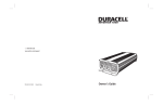
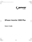
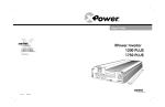
Figure 2-1 AC Panel
2–2
Feature
Description
1
On/Off Switch turns the inverter’s control circuit on and off. This
switch is not a power disconnect switch. Disconnect AC and DC
power before working on any circuits connected to the inverter.
2
Fault light (red): indicates the inverter has shut down due to
inverter overload or over-temperature.
3
Power light (green): indicates the inverter is operating.
4
Display Function Button Press this to display battery voltage,
battery current and AC output power.
5
Status indicator lights: VOLTAGE, CURRENT, AC POWER
When lit, each light indicates which status is being displayed.
975-0444-01-01
Dur_Inverter_3000_Owners_Guide.book Page 3 Tuesday, June 3, 2008 11:51 AM
975-0444-01-01
Feature
Description
6
Status Display: Shows Voltage, Current or AC Power.
VOLTAGE: Indicates battery power at the input terminal of the
inverter in volts (V).
CURRENT: Indicates current drawn from the battery by the inverter
in amps (A).
AC POWER: Indicates the output power from the inverter as a
percentage of total available watts (kW) being utilized.
7
Two 15 A supplementary (overcurrent) protectors
8
3-Prong AC Outlets: Each outlet is protected by a 15-amp breaker.
9
AC Knockout: For hardwiring the inverter.
10
Remote On/Off Connector Port: For connecting the Remote On/
Off Switch.
11
Mounting Flanges (front and rear) allow you to mount the inverter
permanently.
12
Ventilation Openings must not be obstructed for the proper
operation of the inverter. When the inverter is mounted, the
ventilation opening on the DC panel must not point up or down.
2–3
Dur_Inverter_3000_Owners_Guide.book Page 4 Tuesday, June 3, 2008 11:51 AM
Features
DC Panel
3
2
4
5
1
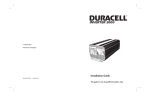
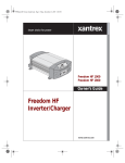
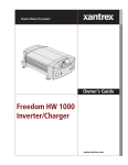
Figure 2-2 DC Panel
2–4
Feature
Description
1
Chassis Ground Lug connects to vehicle chassis, DC grounding
bus or to engine’s negative bus.
2
Ventilation Opening must not be obstructed for the proper
operation of the inverter. When the inverter is mounted, the
ventilation opening on the DC panel must not point up or down.
3
Negative DC Cabling Terminal always connects to the cable
connected to the negative terminal of the battery.
4
Positive DC Cabling Terminal always connects to the cable
connected to the positive terminal of the battery.
5
Serial number of your inverter.
975-0444-01-01
Dur_Inverter_3000_Owners_Guide.book Page 5 Tuesday, June 3, 2008 11:51 AM
Remote Switch
2
1
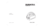
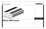
Figure 2-3 Remote Switch
975-0444-01-01
Feature
Description
1
Remote On/Off Switch turns the inverter’s control circuit on and
off. This switch is not a power disconnect switch. Disconnect DC
power before working on any circuits connected to the inverter.
2
Communications Cable is 20 feet (6 m) long.
2–5
Dur_Inverter_3000_Owners_Guide.book Page 6 Tuesday, June 3, 2008 11:51 AM
2–6
Dur_Inverter_3000_Owners_Guide.book Page 1 Tuesday, June 3, 2008 11:51 AM
3
Operation
Chapter 3 explains how to operate the inverter efficiently and effectively.
Specifically, this chapter:
• Gives procedures for operating the inverter from the front panel
• Discusses operating limits and inverter loads
• Discusses battery charging frequency
• Provides information about routine maintenance and recycling
Turning the Inverter On and Off
The On/Off switch on the inverter’s front panel turns the control circuit in
the inverter on and off.
To turn the inverter on and off from its front panel:
• Move the On/Off switch to the On position to turn the inverter on.
• Move the On/Off switch to the Off position to turn the inverter off.
When the switch is Off, the inverter draws a very low current from
the battery.
To turn the inverter on and off from the remote switch:
• Move the On/Off switch to the On position to turn the inverter on.
• Move the On/Off switch to the Off position to turn the inverter off.
When the switch is Off, the inverter draws a very low current from
the battery.
Important: TURNING THE INVERTER OFF WHEN NOT IN USE.
The inverter draws less than 600 mA from the battery with the On/Off switch
turned on and no load connected, but draws far less than this with the switch
turned off. If the switch is left on, even with no loads the inverter will eventually
discharge the battery.
To prevent unnecessary battery discharge, turn the inverter off when you are not
using it.
WARNING: Shock and energy hazard
The inverter’s On/Off switch (on the front panel and remote switch) does not
disconnect DC battery power from the inverter. You must disconnect DC power
before working on any circuits connected to the inverter.
3–1
Dur_Inverter_3000_Owners_Guide.book Page 2 Tuesday, June 3, 2008 11:51 AM
Operation
Operating Several Loads at Once
If you are going to operate several loads from the inverter, turn them on
separately after you have turned the inverter on.
Turning loads on separately helps to ensure that the inverter does not have
to deliver the starting current for all the loads at once, and will help
prevent an overload shutdown.
Display Screen
Battery Voltage
Indicator
Battery Current
Indicator
Output Power
Indicator
3–2
You can monitor important status information on the LED (light emitting
diode) display screen.
To select which information the screen displays, press the Display
Function button. The VOLTAGE, CURRENT and AC POWER lights indicate
what information the screen is showing.
The BATTERY VOLTAGE INDICATOR indicates the DC voltage at the input
terminals of the inverter. At low input currents, this voltage is very close
to the battery voltage. At high input currents, this voltage is lower than the
battery voltage because of the voltage drop across the cable and DC
connections.
The BATTERY CURRENT INDICATOR displays the current draw from the
battery in amps. It will not indicate current draw from other loads
connected to the battery.
The OUTPUT POWER INDICATOR indicates the AC output power in kW.
975-0444-01-01
Dur_Inverter_3000_Owners_Guide.book Page 3 Tuesday, June 3, 2008 11:51 AM
Operating Limits
Operating Limits
Power Output
The Duracell Inverter 3000 can deliver up to 2500 W continuous and up
to 3000 W for five minutes.
Input Voltage
The allowable inverter input (battery) voltage ranges are shown in the
following table:
975-0444-01-01
Operating Condition
Voltage Range
Comment
Normal
10.5–15 V
Optimum
Performance
12.0–13.0 V
Low Voltage Alarm
11.0 V or less
Low Voltage
Shutdown
less than 10.5 V The inverter shuts down to protect the
battery from being over-discharged.
High Voltage
Shutdown
15 V or more
The audible low battery alarm
sounds.
The inverter shuts down to protect
itself from excessive input voltage.
Note: Although the inverter
incorporates over-voltage protection,
it can still be damaged if input
voltage exceeds 16 V.
3–3
Dur_Inverter_3000_Owners_Guide.book Page 4 Tuesday, June 3, 2008 11:51 AM
Operation
Inverter Loads
The inverter will operate most AC loads continuously within its power
rating of 2500 W. However, some appliances and equipment may be
difficult to operate, and other appliances may actually be damaged if you
try to operate them with the inverter. Please read “High Surge Loads” and
“Trouble Loads” carefully.
High Surge Loads
Some induction motors used in freezers, pumps, and other motor-operated
equipment require high surge currents to start. The inverter may not be
able to start some of these motors even though their rated current draw is
within the inverter’s limits. The inverter will normally start single-phase
motors rated at ¾ hp or less.
If a motor refuses to start, observe the BATTERY VOLTAGE INDICATOR
while trying to start the motor. If the indicator drops below 11 V while the
inverter is trying to start the motor, this low voltage condition may be
why the motor won’t start. Make sure that the battery connections are
good and that the battery is fully charged. If the connections are good and
the battery is charged, but the voltage still drops below 11 V, you may
need to use a larger battery or DC input cables that are larger gauge and/or
shorter length.
Trouble Loads
CAUTION: Equipment damage
Some equipment may be damaged by the inverter’s modified sine wave output.
Some appliances, including the types listed below, may be damaged if
they are connected to the inverter:
• Electronics that modulate RF (radio frequency) signals on the AC line
will not work and may be damaged.
• Speed controllers found in some fans, power tools, kitchen
appliances, and other loads may be damaged.
• Some chargers for small rechargeable batteries can be damaged. See
“Precautions for Using Rechargeable Appliances” on page vii for
details.
• Metal halide arc (HMI) lights can be damaged.
If you are unsure about powering any device with the inverter, contact the
manufacturer of the device.
3–4
975-0444-01-01
Dur_Inverter_3000_Owners_Guide.book Page 5 Tuesday, June 3, 2008 11:51 AM
Routine Maintenance
Routine Maintenance
WARNING: Shock and energy hazard
Disconnect DC power before performing any routine maintenance work or
before working on any circuits connected to the inverter.
Minimal maintenance is required to keep your inverter operating
properly. Periodically you should:
• Clean the exterior of the inverter with a damp cloth to prevent the
accumulation of dust and dirt.
• Ensure that the DC cables are secure and fasteners are tight.
• Make sure ventilation openings on the AC and DC panels of the
inverter are not obstructed by blankets and similar items and/or
clogged with accumulated dust and dirt.
Recharging Your Batteries
When possible, recharge your batteries when they are about 50%
discharged or earlier. This gives the batteries a much longer life cycle than
recharging when they are more deeply discharged.
The Duracell Inverter 3000 has a battery low voltage shutdown at
10.5Vdc. With moderate to heavy loads, this will protect against overdischarging the battery. If the inverter is running only light loads it is
advisable to recharge before the inverter low voltage shutdown point is
reached.
Recycling
If it’s rechargeable, it’s recyclable!
Xantrex recognizes its responsibility as a global citizen and is continually
striving to reduce the environmental impact of the work we do and the
products we create. We have taken a step forward to limit our impact on
the natural environment by initiating a battery recycling program.
Xantrex is a licensee of the Rechargeable Battery Recycling Corporation
(“RBRC”), a non-profit public service organization dedicated to recycling
used rechargeable batteries. Through RBRC’s national program and the
975-0444-01-01
3–5
Dur_Inverter_3000_Owners_Guide.book Page 6 Tuesday, June 3, 2008 11:51 AM
Operation
availability of recycling depots for Pb batteries, Xantrex customers can
recycle rechargeable batteries in a convenient and environmentally
friendly way.
If one of your Xantrex battery-integrated products has reached the end of
its useful life, we urge you to dispose of the product correctly and safely.
Xantrex recommends taking the following steps to recycle your product
depending on battery chemistry and size.
Ni-MH, Li-ion or small Pb Batteries (up to 2 lbs. or 1 kg)
If you are recycling a product that contains a Ni-MH, Li-ion or small Pb
battery (up to 2 lbs. or 1 kg) then you can simply drop it off at the battery
drop-box located at any one of the following major retailers.
In Canada: Battery Experts, Battery Plus, Bell World, FIDO, Future
Shop, The Home Depot, Home Hardware, London Drugs, Makita Factory
Service Centers, Personal Edge, Revy, Sears, The Sony Store, The Source
by Circuit City, TELUS Mobility and Zellers
In the USA: Alltel, Batteries Plus, Black & Decker, Cingular Wireless,
Circuit City, The Home Depot, Lowe's, Milwaukee Electric Tool, Office
Depot, Orchard Supply, Porter Cable Service Centers, RadioShack,
Remington Product Company, Sears, Staples, Target, US Cellular and
Verizon Wireless
If you are not sure of the drop-box nearest you, simply call 1-877-2RECYCLE to find the retail collection nearest you.
Pb Batteries (larger than 2 lbs. or 1 kg)
If you need to recycle a Pb battery that is larger than 2lbs. (1kg) then you
may take one of the following three steps to recycle your battery:
•
•
•
dispose of your battery product 'as is' at a battery disposal location or
waste disposal location nearest you.
visit www.xantrex.com and search for "Recycling" to find out
shipping instructions and the current ship-to address of a Xantrex
battery recovery depot.
dispose of the battery inside your product, by first removing it (simple
disassembly may be required) and then taking it to a Sears
Automotive Facility in your area where it can be dropped off for
proper recycling.
* If you are not sure of a Sears Automotive Facility nearest you simply go
to www.Sears.com and select store locator.
3–6
975-0444-01-01
Dur_Inverter_3000_Owners_Guide.book Page 1 Tuesday, June 3, 2008 11:51 AM
4
Troubleshooting
Chapter 4 will help you identify the source of most problems that can
occur with the inverter.
If you have a problem with the inverter, please review this chapter before
contacting place of purchase.
If you are unable to solve a problem and need to contact place of
purchase, record the information in the form “Information About Your
System” on page WA–5.
Common Problems
Buzz in Audio Equipment
Some inexpensive stereo systems may emit a buzzing noise from their
loudspeakers when operated from the inverter. This occurs because the
power supply in the audio system does not adequately filter the modified
sine wave produced by the inverter. The only solution is to use a sound
system that has a higher quality power supply.
Television Reception
When the inverter is operating, it can interfere with television reception
on some channels. If interference occurs, try the following:
1. Make sure that the chassis ground screw on the rear of the inverter is
solidly connected to the ground system of your vehicle.
2. Make sure that the television antenna provides an adequate (“snowfree”) signal, and that you are using good quality cable between the
antenna and the television.
3. Keep the cables between the battery and the inverter as short as
possible, and ensure that the positive and negative cables are run very
close to each other. This minimizes radiated interference from the
cables.
4. Move the television as far away from the inverter as possible.
5. Do not operate high power loads with the inverter while the television
is on.
4–1
Dur_Inverter_3000_Owners_Guide.book Page 2 Tuesday, June 3, 2008 11:51 AM
Troubleshooting
Troubleshooting Reference
WARNING: Electrical shock and burn hazard
Do not disassemble the inverter. It does not contain any user-serviceable parts.
Attempting to service the inverter yourself could result in an electrical shock or
burn.
Some of the following Solutions should be referred to a qualified electrician or
electrical service person.
Table 4-1
#
1
2
Troubleshooting Reference
Error/Warning
Code on Display
AL1: Flashing
Alarm: Beeping
Problem
Possible Cause
Solution
Inverter's Input
Under Voltage
Warning Alarm is
on.
Poor battery condition
Charge the battery.
Install a new battery.
Poor DC wiring
Use proper cable size and
lengths and make solid
connections.
For more information, refer to
“Selecting Cable Sizes” starting
on page 2-6 of the Installation
Guide.
AL2: Flashing
Internal over
Inverter ventilation
Fault LED: Flashing temperature warning openings are obstructed.
Alarm: Beeping
alarm is on.
Ambient temperature is
too high.
Improve ventilation.
Make sure the inverter’s
ventilation openings are not
obstructed.
Reduce the ambient
temperature.
Load applied is above the Reduce the load if continuous
continuous operation
operation is required.
limit.
3
4–2
E01: Steady
Fault LED: Solid
Alarm: Beeping
Inverter is in
undervoltage
shutdown.
AL1 warning code is
ignored. (See possible
causes under error # “1”
in this table).
See solution under error # 1 in
this table.
975-0444-01-01
Dur_Inverter_3000_Owners_Guide.book Page 3 Tuesday, June 3, 2008 11:51 AM
Troubleshooting Reference
Table 4-1
#
4
Troubleshooting Reference
Error/Warning
Code on Display
Problem
Possible Cause
Solution
E02: Steady
Fault LED: Solid
Alarm: Beeping
Inverter is in
overvoltage
shutdown.
High input voltage
Make sure the inverter is
connected to a 12 V battery.
Check the voltage regulation of
the charging system.
5
E03: Steady
Fault LED: Solid
Alarm: Beeping
Inverter is in
Load applied is above the Reduce the load if continuous
overload shutdown. continuous operation
operation is required.
limit.
6
E04: Steady
Fault LED: Solid
Alarm: Beeping
Inverter is in internal AL2 warning code is
over temperature
ignored. (See possible
shutdown.
causes under error # 2 in
this table).
See solution under error # 2 in
this table.
7
E05: Steady
Fault LED: Solid
Alarm: Beeping
Inverter is in short
circuit shutdown.
Disconnect DC power to the
inverter. Have a qualified
electrician check the AC output
connections, wiring, and
appliances for indications of
short circuits.
8
N/A
Low output voltage You are using a voltmeter Use a true RMS reading
(96 VAC–104 VAC) that cannot accurately
voltmeter such as the Fluke 87.
read the RMS voltage of a
modified sine wave.
9
N/A
Low output voltage
on a true RMS
reading voltmeter.
Inverter has shortcircuited.
Low input voltage and the Check the connections and DC
load is close to maximum cables and check if the battery
allowable power.
is fully charged. Recharge the
battery if it is low.
Reduce the load.
10
N/A
No AC output
The inverter is off.
Turn the inverter on.
voltage; no DC input
voltage indication. No power to the inverter. Check if the DC cables are
connected from battery to the
inverter.
Battery disconnect switch Close battery disconnect switch
or breaker is off.
or breaker.
975-0444-01-01
4–3
Dur_Inverter_3000_Owners_Guide.book Page 4 Tuesday, June 3, 2008 11:51 AM
Troubleshooting
Table 4-1
Troubleshooting Reference
#
Error/Warning
Code on Display
11
N/A
Problem
Possible Cause
No AC output
Inverter fuse open.
voltage; there is DC
input voltage
indication.
Solution
Inverter fuses are not
user-replaceable. Return the
inverter. See the Warranty
section for return information.
The inverter could have The inverter has been damaged.
been connected with
Return the inverter. See the
reverse DC input polarity. Warranty section for return
information.
NOTE: Damage caused by
reverse polarity is not covered
by the warranty.
4–4
975-0444-01-01
Dur_Inverter_3000_Owners_Guide.book Page 1 Tuesday, June 3, 2008 11:51 AM
A
Specifications
Appendix A contains electrical performance and physical specifications,
for the inverter.
Important: Specifications are subject to change without notice.
Electrical Performance
Output power at 25ºC (77ºF) ambient
temperature and 12 Vdc input:
• Maximum continuous output power 2500 W
• 5 minute rating
3000 W
Output power at 40ºC (104ºF) ambient
temperature and 12 Vdc input:
• Maximum continuous output power 1900 W
Output current:
• Maximum continuous output
• 5 minute rating
20 Adc
25 Adc
Output voltage range
120 Vac RMS ± 10%
Output waveform
Modified sine wave
Output frequency
60 Hz
Input voltage range
10.5–15 Vdc (12.0 Vdc nominal)
Input current:
• Maximum continuous output
• 5 minute rating
260 A
300 A
Low battery alarm
11.0 V
Low battery cutout
10.5 V
Peak efficiency
90%
No load current draw (switch is on)
<0.6 Adc
A–1
Dur_Inverter_3000_Owners_Guide.book Page 2 Tuesday, June 3, 2008 11:51 AM
Specifications
Physical Specifications
Length
18 1/2" (47 cm)
Width
8" (20 cm)
Height
6 1/4" (16 cm)
Weight
20 lb. (9 kg)
Remote On/Off switch with 20-foot
communications cable
Part number: 100-0864-01-01
Accessory
A–2
975-0444-01-01
Dur_Inverter_3000_Owners_Guide.book Page 1 Tuesday, June 3, 2008 11:51 AM
Warranty and Return
Information
Warranty
What does this warranty cover and how long does it last? This Limited Warranty is provided
by Xantrex Technology Inc. ("Xantrex") and covers defects in workmanship and materials in your
Duracell Inverter 3000. This Warranty Period lasts for 12 months from the date of purchase at the point
of sale to you, the original end user customer, unless otherwise agreed in writing. You will be required
to demonstrate proof of purchase to make warranty claims.
This Limited Warranty is transferable to subsequent owners but only for the unexpired portion of the
Warranty Period. Subsequent owners also require original proof of purchase as described in "What
proof of purchase is required?"
What will Xantrex do? During the Warranty Period Xantrex will, at its option, repair the product
(if economically feasible) or replace the defective product free of charge, provided that you notify
Xantrex of the product defect within the Warranty Period, and provided that Xantrex through inspection
establishes the existence of such a defect and that it is covered by this Limited Warranty.
Xantrex will, at its option, use new and/or reconditioned parts in performing warranty repair and
building replacement products. Xantrex reserves the right to use parts or products of original or
improved design in the repair or replacement. If Xantrex repairs or replaces a product, its warranty
continues for the remaining portion of the original Warranty Period or 90 days from the date of the
return shipment to the customer, whichever is greater. All replaced products and all parts removed from
repaired products become the property of Xantrex.
Xantrex covers both parts and labor necessary to repair the product, and return shipment to the customer
via a Xantrex-selected non-expedited surface freight within the contiguous United States and Canada.
Alaska, Hawaii and outside of the United States and Canada are excluded. Contact Xantrex Customer
Service for details on freight policy for return shipments from excluded areas.
How do you get service? If your product requires troubleshooting or warranty service, contact your
merchant. If you are unable to contact your merchant, or the merchant is unable to provide service,
contact Xantrex directly at:
Telephone: 1 408 987 6359
Website:
www.xantrex.com/support
Direct returns may be performed according to the Xantrex Return Material Authorization Policy
described in your product manual. For some products, Xantrex maintains a network of regional
Authorized Service Centers. Call Xantrex or check our website to see if your product can be repaired at
one of these facilities.
What proof of purchase is required? In any warranty claim, dated proof of purchase must
accompany the product and the product must not have been disassembled or modified without prior
written authorization by Xantrex.
975-0444-01-01
WA–1
Dur_Inverter_3000_Owners_Guide.book Page 2 Tuesday, June 3, 2008 11:51 AM
Warranty and Return Information
Proof of purchase may be in any one of the following forms:
• The dated purchase receipt from the original purchase of the product at point of sale to the end
user; or
• The dated dealer invoice or purchase receipt showing original equipment manufacturer (OEM)
status; or
• The dated invoice or purchase receipt showing the product exchanged under warranty.
What does this warranty not cover? Claims are limited to repair and replacement, or if in
Xantrex's discretion that is not possible, reimbursement up to the purchase price paid for the product.
Xantrex will be liable to you only for direct damages suffered by you and only up to a maximum
amount equal to the purchase price of the product.
This Limited Warranty does not warrant uninterrupted or error-free operation of the product or cover
normal wear and tear of the product or costs related to the removal, installation, or troubleshooting of
the customer's electrical systems. This warranty does not apply to and Xantrex will not be responsible
for any defect in or damage to:
a) the product if it has been misused, neglected, improperly installed, physically damaged or altered,
either internally or externally, or damaged from improper use or use in an unsuitable environment;
b) the product if it has been subjected to fire, water, generalized corrosion, biological infestations, or
input voltage that creates operating conditions beyond the maximum or minimum limits listed in
the Xantrex product specifications including high input voltage from generators and lightning
strikes;
c) the product if repairs have been done to it other than by Xantrex or its authorized service centers
(hereafter "ASCs");
d) the product if it is used as a component part of a product expressly warranted by another
manufacturer;
e) the product if its original identification (trade-mark, serial number) markings have been defaced,
altered, or removed;
f) the product if it is located outside of the country where it was purchased; and
g) any consequential losses that are attributable to the product losing power whether by product
malfunction, installation error or misuse.
Disclaimer
Product
THIS LIMITED WARRANTY IS THE SOLE AND EXCLUSIVE WARRANTY PROVIDED BY XANTREX IN
CONNECTION WITH YOUR XANTREX PRODUCT AND IS, WHERE PERMITTED BY LAW, IN LIEU OF ALL OTHER
WARRANTIES, CONDITIONS, GUARANTEES, REPRESENTATIONS, OBLIGATIONS AND LIABILITIES, EXPRESS
OR IMPLIED, STATUTORY OR OTHERWISE IN CONNECTION WITH THE PRODUCT, HOWEVER ARISING
(WHETHER BY CONTRACT, TORT, NEGLIGENCE, PRINCIPLES OF MANUFACTURER'S LIABILITY, OPERATION
OF LAW, CONDUCT, STATEMENT OR OTHERWISE), INCLUDING WITHOUT RESTRICTION ANY IMPLIED
WARRANTY OR CONDITION OF QUALITY, MERCHANTABILITY OR FITNESS FOR A PARTICULAR PURPOSE.
ANY IMPLIED WARRANTY OF MERCHANTABILITY OR FITNESS FOR A PARTICULAR PURPOSE TO THE EXTENT
REQUIRED UNDER APPLICABLE LAW TO APPLY TO THE PRODUCT SHALL BE LIMITED IN DURATION TO THE
PERIOD STIPULATED UNDER THIS LIMITED WARRANTY.
IN NO EVENT WILL XANTREX BE LIABLE FOR: (a)ANY SPECIAL, INDIRECT, INCIDENTAL OR CONSEQUENTIAL
DAMAGES, INCLUDING LOST PROFITS, LOST REVENUES, FAILURE TO REALIZE EXPECTED SAVINGS, OR
OTHER COMMERCIAL OR ECONOMIC LOSSES OF ANY KIND, EVEN IF XANTREX HAS BEEN ADVISED, OR HAD
WA–2
975-0444-01-01
Dur_Inverter_3000_Owners_Guide.book Page 3 Tuesday, June 3, 2008 11:51 AM
REASON TO KNOW, OF THE POSSIBILITY OF SUCH DAMAGE, (b) ANY LIABILITY ARISING IN TORT, WHETHER
OR NOT ARISING OUT OF XANTREX'S NEGLIGENCE, AND ALL LOSSES OR DAMAGES TO ANY PROPERTY OR
FOR ANY PERSONAL INJURY OR ECONOMIC LOSS OR DAMAGE CAUSED BY THE CONNECTION OF A PRODUCT
TO ANY OTHER DEVICE OR SYSTEM, AND (c), ANY DAMAGE OR INJURY ARISING FROM OR AS A RESULT OF
MISUSE OR ABUSE, OR THE INCORRECT INSTALLATION, INTEGRATION OR OPERATION OF THE PRODUCT.
Exclusions
If this product is a consumer product, federal law does not allow an exclusion of implied warranties. To
the extent you are entitled to implied warranties under federal law, to the extent permitted by applicable
law they are limited to the duration of this Limited Warranty. Some states, provinces and jurisdictions
do not allow limitations or exclusions on implied warranties or on the duration of an implied warranty
or on the limitation or exclusion of incidental or consequential damages, so the above limitation(s) or
exclusion(s) may not apply to you. This Limited Warranty gives you specific legal rights. You may
have other rights which may vary from state to state, province to province or jurisdiction to jurisdiction.
Return Material Authorization Policy
Before returning a product directly to Xantrex you must obtain a Return Material Authorization (RMA)
number and the correct factory "Ship To" address. Products must also be shipped prepaid. Product
shipments will be refused and returned at your expense if they are unauthorized, returned without an
RMA number clearly marked on the outside of the shipping box, if they are shipped collect, or if they
are shipped to the wrong location.
When you contact Xantrex to obtain service, please have your instruction manual ready for reference
and be prepared to supply:
• The serial number of your product
• Information about the installation and use of the unit
• Information about the failure and/or reason for the return
• A copy of your dated proof of purchase
Record these details on page WA-5.
Return Procedure
Package the unit safely, preferably using the original box and packing materials. Please ensure that your
product is shipped fully insured in the original packaging or equivalent. This warranty will not apply
where the product is damaged due to improper packaging.
Include the following:
• The RMA number supplied by Xantrex Technology Inc. clearly marked on the outside of the
box.
• A return address where the unit can be shipped. Post office boxes are not acceptable.
• A contact telephone number where you can be reached during work hours.
• A brief description of the problem.
Ship the unit prepaid to the address provided by your Xantrex customer service representative.
If you are returning a product from outside of the USA or Canada In addition to the above,
you MUST include return freight funds and are fully responsible for all documents, duties, tariffs, and
deposits.
975-0444-01-01
WA–3
Dur_Inverter_3000_Owners_Guide.book Page 4 Tuesday, June 3, 2008 11:51 AM
Warranty and Return Information
If you are returning a product to a Xantrex Authorized Service Center (ASC) A Xantrex
return material authorization (RMA) number is not required. However, you must contact the ASC prior
to returning the product or presenting the unit to verify any return procedures that may apply to that
particular facility and that the ASC repairs this particular Xantrex product.
Out of Warranty Service
If the warranty period for your product has expired, if the unit was damaged by misuse or incorrect
installation, if other conditions of the warranty have not been met, or if no dated proof of purchase is
available, your unit may be serviced or replaced for a flat fee.
To return your product for out of warranty service, contact Xantrex Customer Service for a Return
Material Authorization (RMA) number and follow the other steps outlined in "Return Procedure" on
page WA-3.
Payment options such as credit card or money order will be explained by the Customer Service
Representative. In cases where the minimum flat fee does not apply, as with incomplete units or units
with excessive damage, an additional fee will be charged. If applicable, you will be contacted by
Customer Service once your unit has been received.
WA–4
975-0444-01-01
Dur_Inverter_3000_Owners_Guide.book Page 5 Tuesday, June 3, 2008 11:51 AM
Information About Your System
As soon as you open your Duracell Inverter 3000 package, record the following information and be sure
to keep your proof of purchase.
❐ Serial Number
_________________________________
❐ Product Number
813-3007
❐ Purchased From
_________________________________
❐ Purchase Date
_________________________________
If you need to contact Customer Service, please record the following details before calling. This
information will help our representatives give you better service.
❐ Type of installation (e.g. RV, truck)
___________________________
❐ Length of time inverter has been installed
___________________________
❐ Battery/battery bank size
___________________________
❐ Battery type (e.g. flooded, sealed gel cell, AGM)
___________________________
❐ DC wiring size and length
___________________________
❐ Alarm sounding?
___________________________
❐ Description of indicators on front panel
____________________________
❐ Appliances operating when problem occurred
___________________________
❐ Description of problem
___________________________
______________________________________________________________________________
______________________________________________________________________________
975-0444-01-01
WA–5
Dur_Inverter_3000_Owners_Guide.book Page 6 Tuesday, June 3, 2008 11:51 AM
WA–6