1
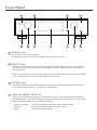
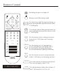
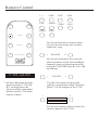
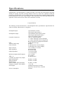
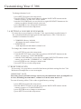
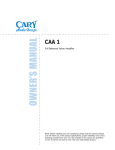
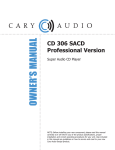
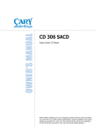
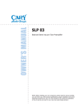
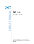
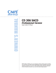
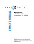
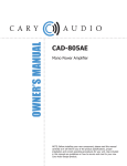
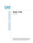
o o o o o o o o o o o o o o o o o o o o o o o o o o o o o o o o o o o o o o o o o o o o o o o o o o o o o o o o o o o o o o o o o o o o o o o o o
OWNER’S MANUAL
o o o o o o o o o o o o o o o o o o o o o o o o o o o o o o o o o o o o o o o o o o o o o o o o o o o o o o o o o o o o o o o o o o o o o o o o o
C 306
Reference Preamplifier
NOTE: Before installing your new component, please read this manual carefully
as it will inform you of the product specifications, proper installation and correct
operating procedures for your unit. Also included in this manual are guidelines
on how to service and care for your new Cary Audio Design product.
C 306
REFERENCE PREAMPLIFIER
C 306
POWER
PREAMPLIFIER
SETUP
MUTE
ENTER
POLARITY
DISPLAY
VOLUME
SELECT
RECORD OUTPUTS
RECORD OUTPUTS
CARY AUDIO DESIGN, INC.,
C 306 PREAMPLIFIER
S/N:
[ ] 117V 50~60Hz
[ ] 220V 50~60Hz
AC MAINS
1
2
IR input
RS 232
Trigger output
2
1
RIGHT CHANNEL INPUTS
LEFT CHANNEL INPUTS
MAIN OUTPUTS
1
2
3
4
5
6
RIGHT CHANNEL
LEFT CHANNEL
6
5
4
3
2
1
Front Panel, Rear Panel & Remote Control
P4-9
Specifications
P.10
Installation
P.11
Customizing your C 306
Operation
Service, Care and Warranty
P.12-14
P.15
P.16-17
IMPORTANT SAFETY INSTRUCTIONS
WARNING: To reduce the risk of fire or electric shock, do
not expose this appliance to rain or moisture. The lightning
flash with arrowhead symbol within an equilateral triangle is
intended to alert the user to the presence of un-insulated
dangerous voltage within the product’s enclosure that may
be of sufficient magnitude to constitute a risk of electric
shock to persons.
CAUTION: To reduce the risk of electric shock, do not remove the cover. There are no user serviceable parts inside.
Please refer to qualified personnel for service.
ALERT: The exclamation point within an equilateral triangle is intended to alert the user of the presence of important
operating and maintenance (servicing) instructions in the literature accompanying the component.
1.
READ ALL INSTRUCTIONS: All the safety and operating instructions of your Cary Audio equipment should be read
before power is applied to the equipment.
2.
RETAIN OWNER'S MANUAL: These safety and operating instructions should be retained for future reference.
3.
HEED WARNING: All warnings on the unit and in the operating instructions should be adhered to.
4.
FOLLOW INSTRUCTIONS: All operating and use instructions should be followed.
5.
CLEANING: Unplug the unit from the wall outlet before cleaning. The unit should be cleaned only as recommended
by the manufacturer.
6.
ATTACHMENTS: Do not use attachments not recommended by the unit manufacturer as they may cause hazards.
7.
WATER AND MOISTURE: Do not use the unit near water - for example, near a bath tub, wash bowl, kitchen sink,
or laundry tub; in a wet basement; or near a swimming pool.
8.
ACCESSORIES: Do not place the unit on an unstable cart, stand, tripod, bracket, or table. The unit may fall,
causing serious injury to a child, an adult, or damage to the unit. Mounting of the unit should follow the
manufacturer's instructions and should use a mounting accessory recommended by the manufacturer.
9.
VENTILATION: Slots and openings in the cabinet are provided for ventilation to ensure reliable operation of the
unit and to protect it from overheating. These openings must not be blocked or covered. The top or bottom panel
openings should never be blocked by placing the unit on a bed, sofa, rug, or other similar surface. The unit should
not be installed in a built-in location such as a bookcase or rack unless proper ventilation is provided. There should
be free space of at least 6 inches (16cm) above the unit and an opening behind the unit.
10. GROUNDING OR POLARIZATION: The unit may be equipped with a polarized alternating current line plug (a
plug having one blade wider than the other). This plug will fit into the power outlet only one way. This is a safety
feature. If you cannot insert the plug fully into the outlet, try reversing the plug. If the plug should fail to fit, contact
a licensed electrician to replace your obsolete outlet. Do not defeat the safety purpose of the polarized plug.
11. POWER SOURCES: The unit should be operated only from the type of power source indicated on the marking
label. If you are not sure of the type of power supplied to your home, consult your unit dealer or local power
company.
12. POWER CORD PROTECTION: Power supply cords should be routed so that they are unlikely to be walked on or
pinched by items placed on or against them. Pay close attention to cords where they enter a plug, or a convenience
receptacle, and the point where they exit from the unit.
13. OUTDOOR ANTENNA GROUNDING: If an outside antenna or cable system is connected to the unit, be sure the
antenna or cable system is grounded so as to provide protection against voltage surges and built-up static charges.
Article 810 of the National Electrical Code, NSI/NFPA 70, provides information regarding proper grounding of the
mast and supporting structure, grounding of the lead-in wire to an Antenna-discharge unit, size of grounding
conductors, location of antenna-discharge unit, connection to grounding electrodes, and requirements for the
grounding electrode.
IMPORTANT SAFETY INSTRUCTIONS
14. LIGHTNING: For added protection for the unit during a lightning storm, or when it is left unattended and unused
for long periods of time, unplug it from the wall outlet and disconnect the antenna or cable system. This will prevent
damage to the unit due to lightning and power line surges.
15. POWER LINES: An outside antenna system should not be located in the vicinity of overhead power lines or other
electric light or power circuits, or where it can fall into such power lines or circuits. When installing an outside
antenna system, take extreme care to keep from touching such power lines or circuits as contact with them might be
fatal.
16. OVERLOADING: Do not overload wall outlets, extension cords, or integral convenience receptacles as this can
result in a risk of fire or electric shock.
17. OBJECT AND LIQUID ENTRY: Never push objects of any kind into the unit through openings as they may touch
dangerous voltage points or short-out parts that could result in a fire or electric shock. Never spill liquid of any kind
on the unit.
18. SERVICING: Do not attempt to service the unit yourself as opening or removing covers may expose you to
dangerous voltage or other hazards. Refer all servicing to qualified service personnel.
19. REPLACEMENT PARTS: When replacement parts are required, be sure the service technician has used
replacement parts specified by the manufacturer or have the same characteristics as the original part. Unauthorized
substitutions may result in fire, electric shock or other hazards.
20. SAFETY CHECK: Upon completion of any service or repairs to the unit, ask the service technician to perform safety
checks to determine that the unit is in proper operating condition.
21. WALL OR CEILING MOUNTING: The unit should be mounted to a wall or ceiling only as recommended by the
manufacturer.
22. HEAT: The unit should be situated away from heat sources such as radiators, heat registers, stoves, or other units
(including amplifiers) that produce heat.
23. IMPORTANT SAFETY NOTE: Before connecting a new component such as the DVD 7 to your audio or home
theater system it is always good practice to make certain that all components are turned off, and preferably
unplugged from their AC power source. Many modern electronics products feature automatic turn-on circuits that
may be activated during an installation, causing the potential for damage to electronic components and/or speakers.
Such damage is not covered by product warranties and Cary Audio specifically disclaims responsibility for any such
damage.
Power Cord: The removable power cord that is shipped with the player is specifically designed to be used with this
product. Other AC cords may be used, so consult your dealer for advice on AC power cords and high quality wire in
your system.
AC Fuse: The fuse is located inside the chassis and is not user serviceable. If power does not
come on, contact your authorized service representative.
Wiring: Cables that run inside of walls should have the appropriate markings to indicate compliance with, and listing
by the UL, CSA or other standards required by the UL, CSA, NEC or your local building code. Questions about cables
inside of walls should be referred to a qualified custom installer, or a licensed electrician or low-voltage contractor.
Do Not Open the Cabinet: There are no user serviceable components inside this product. Opening the cabinet
may present a shock hazard, and any modification to the product will void your warranty. If water or any metal
object, such as a paper clip, coin, or staple accidentally falls inside the unit, disconnect it from the AC power source
immediately and contact Cary Audio for further instructions.
24. RECORDING COPYRIGHT: Recording of copyrighted material for other than personal use is illegal without
permission of the copyright holder.
25. NOTE TO CATV SYSTEM INSTALLER: This reminder is provided to call the CATV system installer's attention to
article 820-40 of the NEC, ANSI/NFPA 70, which provides guidelines for proper grounding and, in particular, specifies
that the cable ground shall be connected to the grounding system of the building, as close to the point of cable entry
as practical.
IMPORTANT SAFETY INSTRUCTIONS
26. FCC INFORMATION FOR USER:
CAUTION: ANY changes or modifications not expressly approved by the party responsible
for compliance could void the user's authority to operate the equipment.
NOTE: This equipment has been tested and found to comply with the limits for a Class B digital device pursuant to
Part 15 of the FCC Rules.
These limits are designed to provide reasonable protection against harmful interference in a residential installation.
This equipment generates and can radiate radio frequency energy and, if not installed and used in accordance with
the instructions, may cause harmful interference to radio communications. However, there is no guarantee that
interference will not occur in a particular installation. If this equipment does cause harmful interference to radio or
television reception, which can be determined by turning the equipment off and on, the user is encouraged to try to
correct the interference by one or more of the following measures:
- Reorient or relocate the receiving antenna.
- Increase the separation between the equipment and receiver.
Connect the equipment into an outlet on a circuit different from where the receiver is connected.
27.
OUTDOOR ANTENNA INSTALLATION/SAFE ANTENNA AND CABLE
CONNECTION: If an outside antenna or cable system is connected to
the equipment, be sure the antenna or cable system is grounded so as to
provide protection against built up static charges and voltage surges,
Section 810 of the national Electrical Code, ANSI/NFP A70 (in Canada,
part 1 of the Canadian Electrical Code) provides information with respect
to proper grounding of the mast and supporting structure, grounding of
the lead-in wire to an antenna discharge unit, size of grounding
conductors, location of antenna discharge unit, connection to grounding
electrodes and requirements for the grounding electrode.
Keep Antenna Clear of High Voltage Power Lines or Circuits
An outside antenna system should be located well away from power lines, electric light or power circuits and where
it will never come into contact with these power sources if it should happen to fall. When installing an outside
antenna, extreme care should be taken to avoid touching power lines, circuits or other power sources as this could
be fatal. Because of the hazards involved, antenna installation should be left to a professional.
Front Panel
9
10
11
C 306
POWER
PREAMPLIFIER
SETUP
MUTE
ENTER
POLARITY
1
2
DISPLAY
VOLUME
SELECT
1
8
3
4
5
6
7
POWER button:
* Press once to turn the power on.
* Press again to set to the"OFF" position and turn the power off.
2
SELECT knob:
* This knob is normally used to select among the various inputs of the C 306, with the
resulting selections being shown in the display window, immediately to the right of
the select knob.
* The select knob is also used during setup to select among various menu items available
( the volume knob is used to actually adjust those items).
3
ENTER button:
* Press this button in conjunction with the setup button; the enter button allows you to
save changes made to the C 306 while in setup mode.
4
ALPHANUMERIC DISPLAY:
* This twenty-character display provides a wide range of information concerning the
operation of the C 306. The information displayed depends on what the C 306 is doing.
* The information displayed is summarized below:
normal operation
balance
setup
selected (audible) input name and volume setting
direction and magnitude of balance offset
setup menus and settings
Front Panel
POLARITY button:
5
* Press this button to invert the polarity ( sometimes called "absolute phase"of the
outputs of the C 306.
6
VOLUME knob:
* This control is normally used to adjust the listening volume. When in BALANCE mode,
this knob is used to vary the relative output of the Left and Right channels. It is also used
during setup for various adjustments.
DISPLAY button:
7
* Press this button to select four levels brightness (including "off" ) for the display,
allowing adjustment for various ambient lighting conditions. When "off" , the display
will turn on for a few seconds when ever a setting is changed.
DISPLAY indicator:
8
* This indicator lights when the display is switched off.
9
MUTE button:
* Pressing this button will reduce the main output level of the preamplifier by a
used-selectable amount, ranging from 1 to 3 decibels. Pressing the MUTE button
a second time without selecting the volume will return it to its previous setting.
10
SETUP button:
* Pressing this button to select the SETUP mode. While in setup mode, the display is
used to show a series of menu choices that allow you to customize the C 306 rather
extensively, to better suit your system's needs and personal preferences.
11
POWER indicator:
* This indicator lights when the player is switched off.
Rear Panel
1
3
2
5
4
1
RECORD OUTPUTS
RECORD OUTPUTS
CARY AUDIO DESIGN, INC.,
C 306 PREAMPLIFIER
S/N:
[ ] 117V 50~60Hz
[ ] 220V 50~60Hz
AC MAINS
1
2
IR input
Trigger output
RS 232
2
1
RIGHT CHANNEL INPUTS
LEFT CHANNEL INPUTS
MAIN OUTPUTS
1
2
3
6
1
4
5
7
6
RIGHT CHANNEL
8
9
LEFT CHANNEL
9
8
6
5
4
3
7
2
1
6
ANALOG RECORD OUTPUT JACK (RCA UNBALANCED):
* Use these jacks for connection to the right-channel and left-channel tape
inputs of your recorder.
2
IR INPUT JACK:
* Use this jack to connect external IR sensors.
3
RS-232 PORT:
* The RS-232 port is used in conjunction with an external controller to control the
operation of the C 306.(This is for custom installation use. Consult your dealer
for more information.)
4
POWER INPUT ( AC IN):
* Connect to an AC power supply using the included power supply cord.
5
DC TRIGGER OUTPUT TERMINALS:
* Connect a device that needs to be triggered by DC + 12V.(Power Amplifiers, CD player...)
Rear Panel
6
BALANCED INPUTS 1-3:
* Accepts right-channel and left-channel balanced signals from source equipment
with balanced outputs.
* The pin assignments of these XLR-type female input are:
2
3
1
Pin 1: Signal ground
Pin 2: Signal + (non-inverting)
Pin 3: Signal - (inverting)
Connector ground lug: chassis ground
Refer to the operating manuals of your balanced-output line-level sources
to verify that the pin assignments of their output connectors correspond to
the C 306. If not, wire the cable so that the appropriate output pin connects
to the equivalent input pin.
7
SINGLE-ENDED INPUTS 4-6:
* Accepts right-channel and left-channel (RCA) inputs from line-level source equipment
such as tuners, CD player, and SACD player.
8
BALANCED MAIN OUTPUTS:
* If your power amplifier is equipped with balanced inputs, it is generally best to use the
balanced outputs on your C 306. A balanced signal from preamplifier to power amplifier
will offer the highest possible performance with the best immunity from common-mode
noise, such as radio frequency interference (RFI). The balanced output signal is made
available by way of precision male XLR connectors (requiring female XLRs on the
preamplifier end of the interconnecting cable).
* The pin assignments of these XLR-type male outputs are:
1
3
2
Pin 1: Signal ground
Pin 2: Signal + (non-inverting)
Pin 3: Signal - (inverting)
Connector ground lug: chassis ground
Refer to your power amplifier's operating manual to verify that the pin
assignments of its input connectors correspond to the C 306. If not, wire
the cable so that the appropriate output pin connects to the equivalent
input pin.
9
SINGLE-ENDED MAIN OUTPUTS:
* Use these jacks for connection to the power amplifiers.
Remote Control
Switching the power on and off.
Muting sound. Resuming sound.
ENTER
DISPLAY
Use the left or right Navigation buttons to
move through menu options shown on the
C 306 Display.
SETUP
-
< SELECTOR >
VOLUME +
1-->
2 ABC
3 DEF
4 GHI
5 JKL
6 MNO
7 PQRS
8 TUV
9 WXYZ
0 a/A
+ 10
CLEAR
L
_
BALANCE
POLARITY
Use the up or down Navigation buttons to
move through menu options shown on the
C 306 Display.
ENTER Use this button to save changes to menu
items in the C 306 from your listening
position.
R
+
DISPLAY Use this button to cycle among four
2
1
1
levels of brightness (including "OFF")
for the display, allowing adjustment
for various ambient lighting conditions.
2
4
3
3
4
5
6
5
6
SETUP
Use this button to access menu functions
of the C 306 from your listening position.
< SELECTOR >
Use this buttons for remote selection of
the various inputs of the C 306.
C 306 main-R/C
-
VOLUME +
Use this buttons to adjust the volume of
the C 306 from Vol. 0 to Vol. 99.
Remote Control
MUTE
1-->
2 AB C
3 DEF
4 GH I
5 JK L
6 MNO
7 PQRS
8 TUVI
9 WXYZ
0 a/A
POWER
VOLUME
+
<
BALANCE
<
Use the ten buttons to create a name
of your own choosing, up to twenty
characters long.
<
INPUT SELECTOR
<
L
BALANCE
R
Use the two buttons to fine-tune the
relative balance of the Left and Right
channel from your listening position
using the VOLUME buttons, in 0.1 dB
increments.
_
C 306 sub-R/C
* All the same name buttons
function on the C 306 subR/C are duplicates the
function of the same name
buttons on the C 306 main
remote control.
POLARITY
+
Use the two buttons to invert the
polarity (sometimes called "absolute
phase" ) of the outputs of the C 306.
1
2
1
2
Use the six buttons to direct select the
various inputs of the C 306.
Specifications_________________________________________
Operating the C 306 Preamplifier is a simple procedure, since each unit is designed for long term
stability in virtually any home operating situation. However, if the unit is operated outside the
parameters outlined in this owner’s manual, damage may result. Please read this manual carefully
before putting your new Cary Audio Design C 306 in operation. The following definitions are
applicable to this manual. Please follow these definitions carefully.
1.1 Specifications
The following section describes the C 306 Preamplifier basic specifications. Specifications are
subject to change without notice or obligation.
Preamplifier Input
Preamplifier Output
Controller Connectors
Gain
Volume control range
Gain resolution
Input overload
Input impedance
Output impedance
Maximum output (MAIN outputs)
THD + N
Crosstalk, any input to any output,
Input unterminated
Input terminated
Residual noise
20Hz to 20kHz, input terminated
Frequency response, 5Hz-100kHz
Power Input
Power Consumption
3 pair balanced on XLR
3 pair single-ended on RCA
1 pair balanced main output on XLR
1 pair single-ended main on RCA
2 pair record outputs on RCA
1 IEC AC mains receptacle
1 - 3.5mm “mini plug” jack for IR input
3 - 3.5mm “mini plug” jack for trigger out
RS 232 full remote configuration interface
18 dB in the line stage
80.0 dB
0.1 dB steps above 50.0 in display
1.0 dB steps below 50.0 in display
12 V on XLR, 6 V on RCA
100 k Ω on RCA
200 k Ω on XLR
< 4.4 k Ω on XLR
< 2.2 k Ω on RCA
16 V on XLR
8 V on RCA
less than 0.001%
less than –120 dB
less than –140 dB
less than –120 dB
+/- 0.1 dB
Configured at factory for either
100-120 or 200-240 VAC, 50-60 Hz
95 Watts
Installation_____________________________________________
This section describes the unpacking and installation procedures for the C 306 Preamplifier.
WARNING
MAKE NO ATTEMPT TO PUT THE C 306 PREAMPLIFIER IN SERVICE WITH
THE TOP COVER REMOVED. CONTACT WITH HIGH VOLTAGE INSIDE THE
C 306 PREAMPLIFIER CAN BE FATAL !!!!!
2.1
Unpacking
All shipping containers have been specifically designed to protect their contents and special care
has been taken to prevent damage under normal shipping conditions. Mishandling should be
evident upon inspection of the shipping container. If the C 306 Preamplifier mechanism or other
damage is found after unpacking and visual inspection, take care not to destroy the evidence so
that the shipping agent may inspect the damage. If necessary, document the damage with
photographs and contact the shipping company immediately.
Carefully remove your C 306 Preamplifier from its packing carton and examine it closely for
signs of shipping damage. It is highly recommended to save all original packing cartons to
protect your C 306 from damage should you wish to store it or ship it for after-sales service.
Replacement cartons and packing are available at a nominal charge from Cary Audio Design, if
ever required.
2.2
Placement
In general, the location of your new C 306 is not critical. However, certain precautions must be
taken to ensure optimum performance. Avoid extremely hot locations such as near radiators or
other heating units. Avoid getting it wet or using it near water. Do not stack the C 306 on top of
a power amplifier. Allow 4-6 inches (10-15cm) above the unit for proper ventilation.
2.3
Power Requirement
The C 306 Preamplifier is designed to operate from AC mains current. The design AC voltage is
either 100-120V /or 200-240Volts AC at 50-60 Hz.
2.4
Connections
Balanced Inputs 1-3 : Accepts right-channel and left-channel balanced signals from source
Equipment with balanced outputs.
Single-ended Inputs 4-6 : Accepts right-channel and left –channel (single-ended) inputs from
Line-levels source equipment such as tuners, CD player.
Balanced Main Outputs :These are for connection to the XLR input jacks of an accompanying
power amplifier or electronic crossovers.
Single-ended Outputs : There are for connection to the RAC input jacks of an accompanying
power amplifier or electronic crossovers.
Customizing Your C 306
3.1 SETUP OVERVIEW:
The C 306 Preamplifier has many provisions for custom-tailoring the system's
operation to match your preferences. The method for modifying any of these
settings is to:
* press the SETUP button on either the front panel or the remote control
to enter the setup mode, accessing the C 306 menu system:
* navigate among different menu items using SELECT knob or the remote
control's NAVIGATE buttons;
* change the value of the selected menu item using either the VOLUME
knob or NAVIGATE buttons on the remote.
* move up or down a level within a menu, or save the change by pressing
ENTER on either the front panel or the remote control.(You can avoid
saving an unwanted change by leaving the menu without pressing ENTER,
by pressing SETUP instead.)
This four-step process gives you extensive control over a wide variety of
setup options, and provides positive feedback that your changes have been
accepted and saved for future use.
3.2 THE MENU SYSTEM:
The complete C 306 Setup menu is shown below for your reference:
CHANNEL 1 RENAME
CHANNEL 2 RENAME
CHANNEL 3 RENAME
CHANNEL 4 RENAME
CHANNEL 5 RENAME
CHANNEL 6 RENAME
MUTE LEVEL-----------> Vol. off ---> Vol. 1---> Vol. 2 ---> Vol.3
VOLUME MODE--------> COMMON ---> INDIVIDUAL
LOAD DEFAULT
EXIT MENU
The C 306's extensive menu system allows you to customize the way the
preamplifier operates, to better suit the needs of your system and your
personal preferences. We will review the following information in more
detail in the coming pages, on an item-by-item basis.
3.3 RENAME:
To facilitate operation in complex multisource systems, the C 306 is capable of
displaying a wide variety of names for each of its six inputs. The available names
are listed below.
CHANNEL 1-6
CD Player 1-3
Surround Processor 1-3
Customizing Your C 306
Equalizer 1-3
Digital Audio Tape 1-3
VCR 1-3
Cassette 1-3
Mine-Dise Player 1-3
CD Recorder 1-3
Phono 1-3
Tuner 1-3
Auxiliary Input 1-3
DA Converter 1-3
CARY CD player 1-3
CARY DVD player 1-3
CARY DA Converter 1-3
CARY Tuner 1-3
Input a new name....._
3.4 CHANGING INPUT NAMES:
To change an input name, use the SETUP menu:
* press SETUP to enter the setup menu
* turn the SELECT knob (or use the up or down NAVIGATE buttons on the
remote) to move to whatever input you want to edit
* turn the VOLUME knob (or use the left or right NAVIGATE buttons on the
remote) to choose the name you want from the list.
* press ENTER to save change to menu items
* press SETUP to exit the setup menu
If none of the default names seems quite right for a given source, you may create
a name of your own choosing, up to twenty characters long. To do so
* press SETUP to enter the setup menu
* turn the SELECT knob (or use the up or down NAVIGATE buttons on the
remote ) to move to whatever input you want to edit
* turn the VOLUME knob (or use the left or right NAVIGATE buttons on the
remote ) to move to "Input a new name....._"
* use the CHARACTER button to select each character in turn, when you
enter the twenty character, you are done
* press ENTER to save change to menu items
* press SETUP to exit the setup menu
(Blank spaces count as 1--> button)
3.5 SELECT A MUTE LEVEL:
There are four mute level modes available in the C 306:
Vol off (factory default)
Vol. 1 (you may prefer to reduce the volume by -60dB when MUTE is pressed)
Vol. 2 (you may prefer to reduce the volume by -59dB when MUTE is pressed)
Vol. 3 (you may prefer to reduce the volume by -58dB when MUTE is pressed)
Customizing Your C 306
To change the mute level:
* press SETUP to enter the setup menu
* turn the SELECT knob (or use the up or down NAVIGATE buttons on the
remote) to move to "MUTE LEVEL" mode
* turn the VOLUME knob (or use the left or right NAVIGATE buttons on the
remote) to choose the mute mode you want
* press ENTER to save change the menu items
* press SETUP to exit the setup menu
3.6 SETTING A VOLUME LEVEL MODE:
You may also set a volume level for the C 306, a particularly useful feature if
the system had different input gain for the input source. The C 306 has two
volume level modes for select:
* COMMON (factory default)
all inputs use same volume level
* INDIVIDUAL
each input has an individual volume level
To change the volume level mode:
* press SETUP to enter the setup menu
* turn the SELECT knob (or use the up or down NAVIGATE buttons on the
remote ) to move to "VOLUME MODE"
* turn the VOLUME knob (or use the left or right NAVIGATE buttons on the
remote ) to select the "COMMON" or " INDIVIDUAL
* press ENTER to save change to menu items
* press SETUP to exit the setup menu
3.7 RESET DEFAULTS:
If necessary, it is possible to reset all of the factory default settings for the C 306
Reference Preamplifier so as to start again.
IMPORTANT NOTE:
Resetting factory default settings caused any customization of the preamplifier to
be lost, including custom names, volume level mode, mute mode. etc.
To reset all setting of the C 306 to the original factory setting:
* press SETUP to enter the setup menu
* turn the SELECT knob (or use the up or down NAVIGATE buttons on the
remote) to move to "LOAD DEFAULT"
* press ENTER to save change to menu items
* press SETUP to exit the setup menu
Operation
C 306
POWER
PREAMPLIFIER
SETUP
MUTE
ENTER
POLARITY
1
1
DISPLAY
VOLUME
SELECT
3
1
NORMAL OPERATION:
The majority of time you spend with your C 306 will be spent in normal operation.
During normal operation, the display indicates the name of the input you have
selected and listening volume. The VOLUME knob increases or decreases the
volume in 0.1dB increments above 50 ( and in 1.0 dB steps below this low level).
The SELECT knob selects the source to be listened to at any point in time. In short,
in normal operation, the C306 acts precisely as you would expect a preamplifier to
act.
2
THE BALANCE:
The BALANCE give you extremely fine control over the relative volume of the left
and right channels, by changing the volume of one relative to the other in increments
of 0.1 dB, up to 10 dB.
3
THE FUNCTION OF POLARITY:
The C 306 allows you to invert the polarity of the music to which you are listening
with the press of a button. People vary in their sensitivity to this aspect of the sound,
and the difference frequently ranges from subtle to inaudible, depending on
microphone technique and other factors in the recording itself. However, some
recordings simply sound correct in one position, and wrong to the other.
We encourage you to experiment with the polarity feature to see what you think works
best for any given recording, understanding that the recordings themselves are not
consistent.
4
THE DC TRIGGER:
The C 306 allows you to use the DC TRIGGER output on the rear panel of the C 306
Controller to turn on some other component automatically when the C 306 itself is on.
You have three trigger outputs, either a 12V level voltage that is present whenever
the C 306 is operational, or absent when the C 306 is in standby.
If you are not sure what the receiving component needs for a trigger signal,
please ask your Cary Audio dealer for assistance.
Service and Care
5.1
C 306 Preampfilier Care and Cleaning
The cabinet housing and front panel of the C 306 may be cleaned with a soft cloth and
Windex® or a mild window cleaner. The frequency of cleaning will be governed by the
operating environment cleanliness. Do not use benzene, harsh or abrasive chemicals to clean the
front or rear panel as they may remove or damage the labels.
5.2
Factory Service
Careful consideration has been given to the design of your C 306 Preamplifier to keep
maintenance problems to a minimum. Any service problems should be referred to our Customer
Service Department phone number (919) 355-0010 from 1-5 PM US East Coast Time Zone. DO
NOT return the C 306 to the factory without a return authorization number (RA) from the
Customer Service Department.
Cary Audio Design, Inc. will assume no responsibility if the shipping company refuses to pay
a damage due to your improper packing or lack of insurance should the unit be lost or damaged
in shipment. Please retain and always use the original shipping carton for the C 306 in the event
that you move or after service is needed.
WARNINGS
MAKE NO ATTEMPT TO PUT THE C 306 INTO SERVICE
WITH
THE
COVER
REMOVED.
CONTACT
WITH THE
POWER SUPPLY SECTION FOUND INSIDE THE UNIT
CAN
BE
FATAL!!
COMPLETELY
REMOVE
THE
AC
POWER PLUG FROM THE WALL BEFORE SERVICING
THE PLAYER.
CAUTIONS
NEVER REMOVE OR INSERT THE
PLUG WHEN THE UNIT IS ON OR
PLUGGED INTO THE WALL.
BACK PANEL AC
THE AC CORD IS
!!PLEASE OBSERVE THE SAFETY DIRECTIONS IN THIS MANUAL!!
UNITED STATES LIMITED WARRANTY
Cary Audio Design warrants to the original United States purchaser for use in the United States that Cary
Audio Design vacuum tube or solid state power amplifiers, surround sound processors or preamplifiers shall
be free from defects in parts or workmanship for three (3) years from the date of the original purchase.
Vacuum tubes, if any are used in the component, are offered a 90 day from purchase date exchange policy
against defects with the exception of the CAVT 300B vacuum tube which has a (1) one year from purchase
date exchange policy. Any digital drive design, whether a Cary Audio Design CD or SACD player or a Cary
Cinema DVD player, has a limited one year parts and labor warranty against defects in manufacture. This is
a limited warrant, for the original purchaser only and does not transfer to any subsequent owner.
During the limited warranty period, Cary Audio Design or an authorized Cary Audio Design service facility
will provide free of charge both parts and labor necessary to correct any defects in material or
workmanship.
To obtain such warranty service, the original purchaser must:
1. Complete and send in the warranty Registration Card within 15 days of purchase.
2. If claiming service the owner must send a fully filled in copy of the original sales receipt along with
any unit sent in for service showing the AUTHORIZED CARY AUDIO DESIGN DEALER’S name, the
new selling price, the buyer’s name, e-mail or phone number and address on the receipt. Blank
receipts will NOT validate the limited warranty for service.
3. Notify Cary Audio Design as soon as possible after the discovery of a possible defect and submit
the following information to determine eligibility for warranty:
(a) The model number and serial number;
(b) A fully filled in copy of the original sales receipt showing the original selling price, purchasers
name and address filled in by an AUTHORIZED CARY AUDIO DESIGN DEALER with the original
date of purchase shown on the form;
(c) a detailed description of the problem.
4. Deliver the product to Cary Audio Design or the nearest authorized service facility or ship with all
freight and insurance charges prepaid, in its original packing container or equivalent, to Cary
Audio.
Correct maintenance, repair and use are important to obtain performance from this product. Therefore,
please carefully read the Operating Manual. This warranty does not apply to any defect that Cary Audio
Design in its sole discretion determines is due to:
1. Improper maintenance or repair, including the installation of parts or accessories that do not
conform to the quality and the specifications of the original parts.
2. Misuse, abuse, neglect or improper installation.
3. Accidental or incidental damage.
WARRANTY DISCLAIMER
Except for the express warranties stated herein, Cary Audio Design disclaims all other warranties including,
without limitation, all implied warranties of merchantability and fitness for a particular purpose. The
foregoing constitutes Cary Audio Design’s entire obligation with respect to this product, and the original
purchaser and any user or owner shall have no other claim for incidental or consequential damages. Some
states do not allow the exclusion or limitation of incidental or consequential damages, so the above
limitation and exclusion may not apply to you. This warranty gives legal rights and you may also have other
rights, which vary from state to state.
EXCLUSIVE REMEDY
Notwithstanding the foregoing, the purchaser’s exclusive remedy for any breach of warranty, express or
implied, is limited to the repair or replacement of the defective unit or the refund of the purchase price, at
the option of Cary Audio Design. Under no circumstances is Cary Audio Design liable for incidental or
consequential damages. Any implied warranties imposed by law terminate one (1) year from the date of
purchase.
INTERNATIONAL PURCHASERS (Export markets)
Cary Audio Design warrants its merchandise to purchasers within the United States exclusively for use within
the United States of America. It provides no other warranties, expressed or implied. If you are living
outside the USA, please consult with your local dealer or distributor to determine the details of your local
warranty.
1020 Goodworth Drive, Apex, NC 27539
phone 919-355-0010
fax 919-355-0013
www.caryaudio.com
o o o o o o o o o o o o o o o o o o o
CARY AUDIO DESIGN
o o o o o o o o o o o o o o o o o o o o o o o o o o o o o o o o o o o o o o o o o o o o o o o o o o o o o o o o o o o o o o o o o o o o o o o o o