1
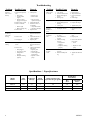
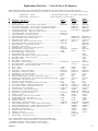
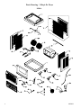
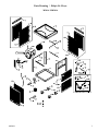
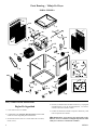
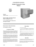
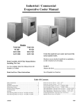
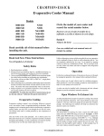
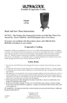
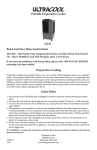
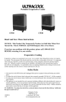
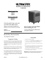
MOBILE EVAPORATIVE
COOLER
Manual Control Units
M201A
M301A
M401A
Remote Control Units
RM301A
RM401A
Circle the model of your cooler and
record the serial number below.
Encierre con un circulo el modelo de su
enfriador y escribe el número de serie abajo.
Read Carefully All Of This Manual
Before Installing The Unit.
Serial #
Lea Con Cuidado Todo Este Manual Antes
De Instalar La Unidad.
Número De Serie
Read And Save These Instructions
Vea el Español en el interior
Safety Rules
Evaporative Cooling
1. Read these instructions carefully.
Evaporative cooling is nature’s way of cooling. When air is moved
over a wet surface, water is evaporated and heat is absorbed. When
stepping out of a swimming pool with the wind blowing, evaporative
cooling makes you feel cool, even though the air may be warm.
The human body itself is cooled primarily by the evaporation of
perspiration.
This unit works on the same principle. Air is drawn across wet
filter pads where the air is cooled by evaporation and then circulated
throughout the building. It is this combination of cooled air and the
movement of air over the skin which makes it feel cool.
Unlike refrigeration systems which recirculate the air, an evaporative
cooler continually brings in fresh air while exhausting old air. You
are completely replacing the air every 2 to 4 minutes by opening
windows or doors or a combination of both. The air is always fresh,
not stale, laden with smoke and odors as happens with refrigerated
air conditioning.
110522-1
2. Unit must be in the Off Position and Unplugged from power
receptacle when installing or performing any maintenance.
3. This cooler will run on 120 volt A.C., 60 Hz (cycle) current
only.
4. Motor and pump are grounded and have an automatic thermal
overload switch which will shut motor off if it overheats. The
motor will restart automatically when it cools down.
5. Pump receptacle is for grounded evaporative cooler pump only.
Do not plug anything else into receptacle.
WARNING: To reduce the risk of fire or electric shock, do not
use this fan with any “solid-state fan speed control device.”
www.championcooler.com
1-09
Operation
Exhaust Air
Manual Control Units
• Pump setting. The rotary switch has 6 settings. The “Pump”
setting will operate the pump without the blower. For best results
turn the switch to “Pump” for a few minutes to wet the pads before
operating the fan.
• High and low cool settings. The “High Cool” and “Low Cool” settings operate both the pump and the blower. Turn the unit to “Low
Cool” when possible. This lower speed allows the air to stay longer
in the wet pads and therefore increases it’s cooling efficiency.
• High and low vent settings. The “High Vent” and “Low Vent”
settings operate the blower without the pump. This is useful on
cool nights or at times when just a fan is desired.
Remote Control Units
These units may be controlled using the 3 buttons on the front panel
of the cooler or with the remote control.
• PUMP button. Pressing this button toggles the pump on and off.
When the LED is lit, the pump is running. For best results turn
on the pump for a few minutes to wet the pads before operating
the fan. The pump must be on while operating the fan for cooling.
You may also want the pump turned off at times when just a fan is
desired.
If the unit is used in an enclosed area, open windows or doors to
ensure adequate exhaust. Without an outlet to exhaust the air,
humidity will build up in the enclosed space and the unit will not
cool adequately.
Cooler Installation
Installing Casters
Note: The installation kit
includes (2) swivel casters with brake, (2) swivel
casters without brake, (16)
tinnerman nuts and (16)
1/4-20 x 1/2 screws.
• Place the unit on its side.
Place the tinnerman nuts on
the caster bracket on the bottom pan as shown in figure
1.
• Attach the casters to the
brackets with the screws provided.
Fig. 1
Connecting Water
• FAN button. Pressing this button will cycle the fan through High
Speed / Low Speed / Off. The LED’s on the front of the control
indicate wether the fan is on high speed, low speed or off (no LED’s
lit). Note: There will be a 2 second delay between a button press
and the operation of the fan.
• Install drain assembly. Place the
nipple through the hole in the pan,
with the rubber washer between the
pan and the head of the drain nipple
(Fig. 2). Thread nut onto nipple and
draw up tight against bottom of pan.
Thread the drain cap to the nipple and
tighten water tight.
• ON/OFF button. Pressing this button while the pump or fan is on
will turn everything off. Pressing it again while in the off state will
return the fan and pump to their previous operating settings. When
first plugging in the cooler or after power has been interrupted,
pressing the On/Off button will start the cooler in the default state
which is with the pump on and the fan on high.
• Install float valve. Refer to figure 3. Install the valve in the provided hole in the corner post ((R)M301A, (R)M401A) or louvered
side (M201A) using the provided washer and nut. Install the
included garden hose adapter to the float as shown if attaching a
garden hose to the unit. A 1/4 inch water line may also be used to
supply a continuous amount of water to the unit.
• Remote Control. To operate the cooler with the remote you must
be within 20 feet and in sight of the cooler. Aim the remote at the
front panel. The buttons on the remote control have the same functions as the buttons on the front panel of the cooler. The remote
uses two AAA alkaline batteries which are included. A holder for
mounting on a wall is also included with the unit.
• Fill pan with water. You may fill the pan manually for up to 3
hours of cooling. For automatic filling you may attach a garden
hose to the garden hose adapter or a 1/4 inch water line to the float
valve.
Nipple
Rubber Washer
Bottom Pan
Nut
Drain Cap
Fig. 2
Wiring Diagrams
Manual Control
Remote Control
Blower
Motor
Green
2
Green
Pump
Motor
Blower Motor
Switch
Black-Hi
Black
3
Red-Lo 1
White-Com.
Green-Ground
Control
Blower Panel
White-Com.
4
B
2
A
Plain
Hi
Low
Gnd
Com.
Black
Red
Green
White
Ground
Screw
Ground
Wire
Junction Box
(RM301A)
Ribbed-Com.
Pump
Motor
110522-1
Note: Do Not Overfill. Fill water to a maximum height of 2 1/2
inches (approximately 1 inch from the top of the bottom pan). If
using a garden hose, the float will need to be adjusted to maintain
this water level. This can be accomplished by bending the float
rod.
Nut
Float Body
Garden Hose
Adapter
Washer
Float Rod
Fig. 3
Maintenance
WARNING: Before doing any maintenance be sure power is
off and unit is unplugged. This is for your safety.
Annual Maintenance
• Oil bearings. The blower bearings (M401A & RM401A only)
and cooler motor in this unit should be oiled with a few drops of
non-detergent 20/30 weight oil once each year. The motor does
not need oil if it has no oil lines for oiling. Motors that have no oil
lines are lifetime oiled at the factory and require no further oiling
for the life of the unit.
CAUTION: Do not over oil. Over oiling can cause motor burn
out, due to excessive oil getting into motor winding.
• Change Pads. Pads should be replaced once or twice a season,
depending upon the length of the season. At the beginning and at
mid season a clean pad is more absorbent and efficient and will
deliver substantially more cool air.
• Check belt and belt tension. This applies only to models
(R)M401A which are belt driven. Models M201A and (R)M301A
have direct drive motors. Check the belt for any cracks or wear and
replace if necessary. Check the tension on the belt. A 3 lb. force should
deflect the belt 3/4 inches (see Fig.
4). Readjust belt if needed.
3 Lb.
3/4 Inches
Fig. 4
• Clean pump. Cleaning the pump
is necessary once a year at start-up.
For your safety, turn unit off and unplug unit and pump. Remove
the pump from the mount slot. Remove the base of the pump (Fig.
5). Clean the pump and turn the impeller to ensure free operation.
Remove the pump spout and check for any blockage. After cleaning, reinstall the base onto the
pump. Press firmly to make sure
Remove
it is secure. Reattach the pump
Base
to the mount in the cooler using
the plastic retainer to ensure that
the pump will not overturn. Do
not forget to replace the spout
Impeller
and water delivery tube onto the
pump outlet.
Fig. 5
Routine Maintenance
• Drain water. It is recommended to drain the water from the
cooler at least once a week. Keeping fresh water in the pan will
help prevent scale and mineral deposits accumulation on the pads.
Always drain all of the water out of the cooler when not in use for
prolonged periods, and particularly at the end of the season.
• Unplug unit from power supply during extended periods of
non-use.
• Cover unit or store inside when not in use.
By following the operating, installation, and maintenance suggestions
as outlined, you can get many years of efficient and satisfactory
service from your cooler. In the event additional information is
desired, your dealer will be more than glad to assist you in every
possible way.
Register your product online at www.championcooler.com/eac/onlineregistration-eac.htm
Limited Warranty
This warranty is extended to the original purchaser of an evaporative cooler installed and used under normal conditions. It does not cover damages incurred through accident, neglect, or abuse by the owner. We do not authorize any person or representative to assume for us any other or different liability
in connection with this product.
Terms And Conditions Of The Warranty
For Two Years from date of purchase, we will replace any original component provided by Champion Cooler which fails due to any defect in material or
factory workmanship only.
Exclusions From The Warranty
We are not responsible for replacement of cooler pads. These are disposable components and should be replaced periodically. We are not responsible for
any incidental or consequential damage resulting from any malfunction.
We are not responsible for any damage received from the use of water softeners, chemicals, descale material, plastic wrap, or if a motor of a higher horsepower than what is shown on the serial plate is used in the unit.
We are not responsible for the cost of service calls to diagnose cause of trouble, or labor charge to repair and/or replace parts.
How To Obtain Service Under This Warranty
Contact the Dealer where you purchased the evaporative cooler. If for any reason you are not satisfied with the response from the dealer, contact the Customer Service Department: Champion Cooler, 5800 Murray Street, Little Rock, Arkansas 72209. 1-800-643-8341. [email protected].
This limited warranty applies to the original purchaser only.
110522-1
3
Troubleshooting
Problem
Failure to
start or no air
delivery
Possible Cause
1. No electrical power to
unit
• Fuse blown
• Circuit breaker
tripped
• Electric cord unplugged or damaged
2. Belt too loose or tight
3. Motor overheated
• Belt too tight
• Blower bearings dry
4. Motor locked
Inadequate
air delivery
with cooler
running
1. Insufficient air exhaust
2. Belt too loose
3. Pads plugged
Inadequate
cooling
1. Inadequate exhaust in
house
2. Pads not wet
• Pads plugged
• Open spots in pads
• Trough holes
clogged
• Pump not working
properly
Remedy
Problem
1. Check power
1. Open windows or
doors to increase air
flow
2. Adjust belt tension or
replace if needed
3. Replace pads
1. Open windows or
doors to increase air
flow
2. Check water distribution system
• Replace pads
• Repack pads
• Clean trough and
unplug holes
• Replace or clean
pump
Remedy
Motor cycles
on and off
1. Low voltage
2. Excessive belt tension
3. Blower shaft tight or
locked
4. Bearings dry
1. Check voltage
2. Adjust belt tension
3. Oil or replace bearings
4. Oil bearings
Noisy
1. Bearings dry
2. Wheel rubbing blower
housing
3. Loose parts
1. Oil bearings
2. Inspect and realign
Excessive
humidity in
house
1. Inadequate exhaust
1. Open doors or windows
Musty or
unpleasant
odor
1. Stale or stagnate water
in cooler
2. Pads mildewed or
clogged
3. Pads not wetting
properly
• Trough holes
clogged
• Pump not working
properly
1. Drain pan and clean
pads
2. Replace pads
1. Float arm not adjusted
properly
2. Drain assembly leaking
1. Adjust float
• Replace fuse
• Reset breaker
• Plug in cords or
replace if damaged
2. Adjust belt tension
3. Determine cause of
overheating
• Adjust belt tension
• Oil blower bearings
4. Replace motor
Possible Cause
Water draining from
cooler
3. Tighten loose parts
3. Check water distribution system
• Clean
• Replace or clean
pump
2. Tighten nut and drain
cap.
Specifications / Especificaciones
4
Model
Modelo
Volts
Voltios
Amperage
Ameraje
Speed
Velocidad
Water Capacity (gal)
Capacidad de Agua (galón)
M201A
M301A / RM301A
M401A / RM401A
115
115
115
4.7
7.9
10.5
2
2
2
4.8
9.2
11.3
Weight (lbs.)
Peso (libras)
Dry
Operating
Seco
Lleno
62
102
107
184
169
263
110522-1
Replacement Parts List / Lista De Piezas De Repuesto
When ordering parts, please be sure to furnish the following information on all orders. Failure to do so may delay your order. /
Al pedir piezas, incluya toda la información siguiente con su pedido. El no proporcionar toda esta información resultará en una demora.
1. Model number / Modelo
2. Serial number / Número de serie
3. Description and part number / Descripción y número de pieza
4. Date of purchase / Fecha de compra
No.
M301A
M401A
N° Description / Descripción
M201A
RM301A
RM401A
1.
Bottom Pan / Base De La Caja.......................................................................................322902-503
322904-504
322903-508
2.
Top Pan / Tapa ................................................................................................................110844-1
110844-2
110844-3
3.
Blower Support Panel / Panel De Soporte Para El Soplador ........................................222908-004
322908-005
322908-006
4.
Corner Post, With Float Hole / Poste De Esquina, Con Agujero Para Flotador ...........224003-022
224003-032
5.
Corner Post, For Pump Mount / Poste De Esquina, Para Montar La Bomba ...............224003-046
224003-047
6.
Top Support Bracket, Side / Soporte De La Tapa, Lado ................................................218170-002 (3)
218170-002 (2)
7.
Top Support Bracket, Back / Soporte De La Tapa, Posterior ........................................218170-001
218170-003
8.
Louvered Side, Right / Reja Lateral, Derecha ...............................................................324102-112
9.
Louvered Side, Left / Reja Lateral, Izquierda ................................................................324102-212
10. Louvered Side Assembly / Montaje De Reja Lateral .....................................................324006-403 (3)
324006-206 (2)
11. Water Trough, Side / Canal De Agua, Lateral ...............................................................226003-001 (3)
226003-001 (2)
12. Filter, Side / Filtro, Lateral.............................................................................................110131-1 (2)
110131-3 (3)
110131-4 (2)
13. Pad Retainer, Side / Soporte Para El Filtro, Lateral......................................................3PW-1 (4)
3PW-3 (9)
3PW-3 (6)
14. Louvered Back Assembly / Montaje De Reja Posterior ................................................324102-303
324007-305
15. Water Trough, Back / Canal De Agua, Posterior ...........................................................226003-002
16. Filter, Back / Filtro, Posterior ........................................................................................110131-2
110131-5
17. Pad Retainer, Back / Soporte Para El Filtro, Posterior .................................................3PW-2 (2)
3PW-5
18. Blower Housing / Caja De La Rueda .............................................................................324102-008
324120-001
324103-009
19. Blower Wheel, Left / Rueda, Izquierda ..........................................................................110747
110764
15BW
19A. Blower Wheel, Right / Rueda, Derecha .........................................................................110748
20. Shaft, Blower Wheel / Eje De La Rueda ........................................................................110182
21. Bearings, Blower Wheel Shaft / Cojinetes Del Eje De La Rueda ..................................110351 (2)
22. Pulley, Blower Wheel / Polea De La Rueda...................................................................110275
23. Drive Belt / Correa .........................................................................................................110212
24. Pulley, Motor / Polea Del Motor ....................................................................................110273
25. Motor Mount / Montura Del Motor................................................................................216002-001 (2)
218109-001 (2)
314003-025
26. Motor Rail Grommet / Arandela De Goma Para La Montura Del Motor .....................110731 (4)
27. Motor Mount Clips / Seguros Para Montar Motor ........................................................314005-001
28. Motor / Motor .................................................................................................................110441-C
110441-2
110447
29. Pump / Bomba ................................................................................................................110436
110436
110436
30. Pump Screen / Malla Para La Bomba ............................................................................281001-001
281001-001
281001-001
31. Pump Mount / Montura De La Bomba ...........................................................................218001-032
218001-031
218001-031
32. Pump Retainer / Sujetador De La Bomba ......................................................................110714
110714
110714
33. Tube, Water Delivery / Tubo De Agua............................................................................310716
310716
310716
34. Water Distributor Assembly / Sistema Del Distribuidor De Agua .................................3D-1
3D-2
3D-3
35. Retaining Clip, Water Distributor / Retén Plástico Para El Distribuidor De Agua .......110723 (5)
110723 (6)
110723 (6)
36. Drain Assembly / Montaje De Desagüe .........................................................................3DA-1
3DA-1
3DA-1
37. Float Valve / Válvula Del Flotador ................................................................................FL-C
FL-C
FL-C
38. Garden Hose Adapter / Adaptador Para Manguera De Jardín ......................................110824
110824
110824
39. Swivel Caster w/ Brake / Rueda Giratoria Con Freno ..................................................110822-5 (2)
110822-5 (2)
110822-5 (2)
40. Swivel Caster w/o Brake / Rueda Giratoria Sin Freno ..................................................110822-2 (2)
110822-2 (2)
110822-2 (2)
41. Tinnerman Nut / Tuerca Tinnerman ...............................................................................110916 (16)
110916 (16)
110916 (16)
42. Lower Front Panel / Panel Delantero Inferior ...............................................................110844-6
110844-5
110844-5
43. Mounting Clip / Sujetador De Panel Delantero .............................................................110844-7 (2)
110844-7 (2)
44. †Switch Box / Caja Para El Interruptor ..........................................................................222010-002
222010-002†
222010-002†
45. †Switch / Interruptor ......................................................................................................110425
110425†
110425†
46. †Pump Receptacle / Tomacorriente De La Bomba.........................................................110395-1
110395-1†
110395-1†
47. †Electrical Power Cord / Cable Eléctrico ......................................................................110394
110394†
110394†
48. †Electrical Motor Cord / Cable Eléctrico Del Motor .....................................................110366†
49. †Bushing / Pasacable .....................................................................................................110705
110705†
110705†
50. †Knob, Switch / Perilla Del Interruptor ........................................................................110839-006
110839-006†
110839-006†
51. †Grill Assembly, Manual Units / Rejilla Completa, Control Manual ............................110844-41
110844-41†
110844-41†
51. ‡Grill Assembly, Remote Units / Rejilla Completa, Control A Distancia......................110844-42‡
110844-42‡
52. ‡Electrical Control Assembly / Montaje De Control Electrónico ...................................110400‡
110400‡
53. ‡Dress Ring / Anillo Decorativo......................................................................................110403‡
110403‡
54. ‡Remote Control / Mando A Distancia ...........................................................................110401-1‡
110401-1‡
55. ‡Bushing / Pasacable .....................................................................................................110733‡
110733‡
56. ‡Junction Box / Caja De Conexiones .............................................................................281004-002‡
57. ‡Junction Block / Bloque De Conexiones ......................................................................110404‡
NOTE: Standard hardware items may be purchased from your local hardware store.
NOTA: Artículos de uso corriente pueden comprarse en la ferretería de su localidad.
† For Manual Control units. / Para las unidades de control manual.
‡ For Remote Control units. / Para las unidades de control a distancia.
110522-1
5
Parts Drawing / Dibujo De Piezas
M201A
6
110522-1
Parts Drawing / Dibujo De Piezas
M301A / RM301A
110522-1
7
Parts Drawing / Dibujo De Piezas
M401A / RM401A
Lea y Conserve Estas Instrucciones
Reglas De Seguridad
4. El motor y la bomba están conectados con la tierra, y se apagarán
automáticamente en caso de sobrecalentamiento. Los motores
volverán a funcionar cuando se enfrían.
1. Lea las instrucciones con cuidado.
2. La unidad debe estar Apagada y Desconectada de la electricidad
cuando se instale o haga cualquier mantenimiento.
3. Su enfriador funciona sólo con corriente alterna de 120 voltios,
60 Hz. (ciclos).
8
5. Enchufe una bomba del enfriador evaporativo solamente y nada
más al receptáculo de la bomba.
ADVERTENCIA: Para reducir el riesgo de incendio o toques
eléctricos, no use este ventilador con ningún “dispositivo de estado
sólido para controlar la velocidad del ventilador.”
110522-1