1
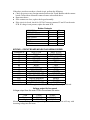
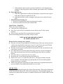
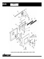
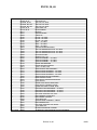
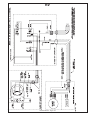
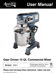
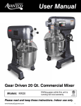
Raised Vent
RV30, 36, 46
Service Manual
RVC
RVR
Issued By:
Technical Service
Date Issued:
4-2004
Page
Distribution:
Service/Parts
Subject:
Service Issue
Product Type:
Ventilation
Model No:
RV
1
of
1
Supercedes:
Bulletin No:
04-07
RV Speed Control
RV30, 36 & 48 produced after 1/30/04: units equipped with the 12A control board
part # 72881, the mounting screw for the main terminal board could be in contact
with the heat sink on the control board. If the board is touching the heat sink
symptoms will include: inability to change speeds at the touch pad, and the blower
operating as soon as the unit is prompted to rise.
In some cases, the board may be damaged, however, preventing the screw from
contacting the heat sink will usually correct the malfunction.
Units affected are RV 30, 36, & 48 with serial # prefix of 0405 and above. If you
have questions, please contact Technical Service 800-35-DACOR.
Theory of Operation
When keypad up/down button is pushed, contacts on the main PCB close between #12
and #13. Closing these contacts activates the triac for the sleeve motor which is
connected to terminals L3 and N3 on the main PCB. The motor then raises the intake
assembly until contact is made with the up stroke limit switch opening the circuit and
reversing the electronic switch on the main PCB. When pressed again, the cycle reverses
itself and stops in the retracted position.
VENT PCB DIAGNOSIS (ALL MODELS)
Warning – With the motor disconnected, and the vent in the down position, 120VAC will
be present between terminals L2 and N2 on the main PCB. When testing for a load, the
motor must be connected to these terminals.
Vent in Down position
120 Volts AC
Zero Volts AC
120 Volts AC
120 Volts AC
120 Volts AC
Vent in up position and under
load with motor connected:
120 Volts AC
Zero
120
Expected Voltage Reading:
across L2 and N2 with no load (wires
disconnected from motor)
Voltage reading across L2 and N2 with
motor connected (under load)
Reading from L2 to Ground with motor
connected
Reading from N2 to Ground with Motor
connected
Reading from L2 to Ground with Motor
disconnected
From L2 to Ground
From N2 to Ground
Reading across L2 and N2
Keypad Diagnosis
(All Models)
Of all the returned keypads the most common problem is poor electrical contact between
the Touch Pad and the Contact Board. In the majority of these cases the Keypad
Assembly is replaced unnecessarily. Before replacing the Keypad Assembly check for a
foreign material between the Touch Pad and the Contact Board. Examples of foreign
material include grease, cooking residue, moisture, or residue from cleaning agents.
Circuit board cleaner or equivalent (available from electronic supply stores) should be
used to clean the keypad assembly.
To diagnose the keypad:
1. Disconnect the Keypad Molex plug at the Main PCB and attach leads of an ohmmeter
to pins #12 and #13.
2. Push the UP/DOWN button. This must show a closed circuit.
If the above test does not show a closed circuit, perform the following.
♦ Check for grease or any foreign material between the Touch Buttons and the contact
board. Clean with an electronic contact cleaner as described above.
♦ Repeat test above.
♦ If the contacts are clear, replace the keypad assembly.
♦ If the circuit is closed, check for 120VAC between contacts N3 and L3 on the main
PCB. If voltage is not present, replace the main PCB.
Button Contacts
UP/DOWN
12
HIGH SPEED
11
MEDIUM SPEED
5
LOW SPEED
12
DELAY
14
STOP
12
CLEAN
11
13
10
10
10
5
14
14
KEYPAD – CIRCUIT BOARD MOLEX PLUG WIRING ORDER
TERMINAL #
OLD STYLE
NEW STYLE
#1
BROWN
DARK GREEN
#2
RED
BRN W/WHITE
#3
ORANGE
BLUE
#4
YELLOW
BROWN
#5
GREEN
GRAY
#6
BLUE
RED
#7
PURPLE
PURPLE
#8
BRN W/WHITE
PINK
#9
RED W/WHT
WHITE
#10
ORANGE W/BLACK
ORANGE
#11
YELLOW W/BLACK
BLACK W/WHITE
#12
GREEN W/BLACK
BLACK
#13
BLUE W/BLK
BLACK
#14
PURPLE W/WHITE
LT GREEN
Wires Are Numbered 1 Through 14 And The Molex Plug Is Physically Numbered.
Voltage output for fan speed
Voltage output from the main PCB to the exhaust fan motor:
Low
77VAC
87VAC
Medium
94VAC
101VAC
High
115VAC
115VAC
Measurements of voltage are average readings, as actual measurements will vary with
incoming voltage into the home.
Possible Failures
A. Unit dead on arrival
1. Check the keypad to be sure that the Lockout Mode has not been activated (look
for the two LED’s) To disable press and hold the HIGH and LOW button for a
minimum of 1.0 second.
2. Check voltage between N1 and L1 on the main PCB. The voltage should be
120VAC. If voltage is not present check the incoming power supply and all
wiring connections. A miswired unit may cause the PCB to fail.
3. Check the Keyboard wiring harness and Molex receptacle for open or loose wires.
Make sure that the Molex plug is securely attached to the main PCB.
B. Unit will not raise or Lower:
1. Check limit switches and the connecting wiring.
2. Check main PCB between L3 and N3 for 120 VAC when the UP/DOWN key is
pressed. If voltage is not present check between terminals #12 and #13 on the
PCB for continuity when the up/down key is depressed. If there is no voltage or
continuity the PCB is defective and must be replaced.
C. Vent will go up but motor will not run:
1. Check for proper wiring to the exhaust motor. The majority of motors failing to
operate on new units are the result of incorrect installation wiring.
2. Look for miswired or defective limit switches. Review the functional and
operational descriptions of the limit switches.
3. Check voltage output to exhaust motor. This should be 120VAC on the highspeed setting.
4. Raise the vent or press the high-speed button. Spin the exhaust motor, if motor
runs check capacitor.
5. Check for defective PCB. See section on PCB Diagnosis.
D. Vent will not stop, goes up and down continuously:
1. Check for misaligned or defective limit switches.
2. Check wiring between the limit switches and main PCB.
E. Blower runs only when the vent is down.
1. Check for proper wiring at the PCB
2. Check for defective limit switches
3. Check for defective PCB. See section on PCB Diagnosis.
F. Vent only goes part way up; user must push keypad repeatedly.
1. Check for a loose wiring harness or loose wire connections.
2. Check for dirt or grease on the Touchpad and Contact board. See section on
KeyPad diagnosis.
3. Check for defective PCB. See section on PCB diagnosis.
G. Vent operates by itself:
For this to occur the main PCB is detecting some type of electrical interference. Check
for the following:
1. The installation instructions require a correctly grounded and dedicated
circuit. If the unit is connected to a non-dedicated circuit refer the customer
back to the installer and inform them that they will be responsible for future
repairs until the wiring is corrected.
2. If the problem can be traced or associated with the use of an electronic gas
cooktop (of any design) then a filter assembly (part number 86325) should be
installed.
H. Filter light stays on:
1. If the filter light remains on after the filter button is depressed remove power
to the unit to deposit to replace the P.C.B
2. If the light remains on after resetting the microprocessor, replace the main
PCB
I. Main PCB keeps shorting out:
1. Check for reversed polarity on the incoming power supply.
2. Check for possible miswire of the exhaust motor.
Quick Check – Main PCB:
If the vent is not working at all
♦ Check the fuse on the main PCB
♦ If the fuse is good check for continuity between the fuse and L3 (drive motor
terminal)
♦ If this circuit is open the PCB is bad and must be replaced.
When reassembling please be sure all the wiring is correct.
KEYPAD, KEYBOARD REPLACEMENT
RV SERIES RAISED VENT
Removal of the cooktop is not required.
♦ Raise the vent sleeve by pressing the UP/DOWN button. If the unit is dead, raise the
vent by removing the black motor sleeve wires L3 and N3 from the main PCB and
hook direct to a power source (Auxiliary power cord, pigtail etc)
♦ With the vent in up position turn off the electrical power to the vent and remove the
vent electric cover plate.
♦ If a cabinet blower is used, disconnect the blower from the vent by loosening the
three wing nuts located above the blower and lifting up on the blower retaining
bracket.
♦ If a remote blower is used remove the cover plate.
♦ Disconnect the 14 wire Molex plug from the main PCB.
♦ Remove the screws, 1 on each side of the sleeve. Lift topcap assembly from the
sleeve assembly. Guide the Molex plug through the electric box and through the
channel in the sleeve assembly.
♦ Remove the right end cap (pressed in). Slide out the bezel, keypad and keyboard as
one unit. Replace desired part and reinstall in reverse order.
OFF BUTTON
Pressing and releasing this button will switch off the fan motor. The fan speed indicators
will be switched off and the OFF LED will be switched on. The OFF LED will only be
switched on to indicate the fan motor is switched of whenever the UPPER LIMIT switch
is closed.
If DELAY OFF function is on, this will also be cancelled by pressing the OFF button.
DELAY OFF BUTTON
This button has a toggle action. Pressing and releasing this button will enable the fiveminute DELAY OFF function. Pressing and releasing this button again will cancel the
selected DELAY OFF function.
When the DELAY OFF function is selected, the fan will continue to operate at the
selected speed for five minutes and then turn off automatically.
During this five-minute interval the fan speed can be changed by pressing and releasing
the HIGH, MEDIUM, or the LOW button.
FAN SPEED – LOW BUTTON
Pressing and releasing this button will select the low speed for the fan. The LOW speed
LED indicator will be on indicating the selected fan speed. Both the MEDIUM and
HIGH LED will be off.
FAN SPEED – MEDIUM BUTTON
Pressing and releasing this button will select the medium speed for the fan. The
MEDIUM speed LED indicator will be on and both the LOW and HIGH LED will be off.
FAN SPEED -HIGH BUTTON
Pressing and releasing this button will select the HIGH speed for the fan. The HIGH
speed LED indicator will be on and the LOW and MEDIUM LED will be off.
CLEAN FILTER BUTTON
When the total number of hours that the fan has operated exceeds 10 hours, the FILTER
CLEAN LED will be on indicating the fan has accumulated over 10 operating hours.
Pressing and releasing the FILTER button enables this 10-hour timer to reset, and turns
off the FILTER CLEAN LED. This button only becomes operational after the FILTER
CLEAN LED is on.
UP/DOWN BUTTON
This button is used to control the sleeve motor. Pressing and releasing this button will
stop the fan motor and cancel the DELAY OFF function (if selected). However, this
button can carry out three different operations to the sleeve motor.
If the sleeve motor is in its upright position, pressing and releasing this button will start
the sleeve motor and lower the vent.
Pressing and releasing this button again before the vent has lowered to its lowest position
will stop the sleeve motor. After the vent has stopped, pressing and releasing this button
again will start to lower the vent until the LOWER LIMIT switch is closed or the
UP/DOWN BUTTON is pressed again.
UPPER LIMIT SWITCH
When this limit switch is closed during the sleeve’s upward motion, the sleeve motor will
be switched off. This indicates the sleeve is in its full upright. At this instance the fan
motor will automatically select HIGH SPEED. Furthermore, the FAN SPEED buttons
and the delay off button will then become operational.
LOWER LIMIT SWITCH
When this limit switch is closed during the sleeve’s downward motion, the sleeve motor
will be switched off automatically. This indicates the sleeve is in its lowest position.
LOCKOUT FUNCTION
Pressing and holding the LOW button and the HIGH speed button for more than 0.5
seconds will select the clean function. ONCE THIS FUNCTION IS ACTIVATED, ALL
THE BUTTONS WILL BE DISABLED UNTIL THIS FUNCTION IS ENABLED BY
AGAIN PRESSING AND HOLDING THE TWO SPEED BUTTONS FOR 0.5
SECONDS. This function will permit the cleaning of the unit without accidentally
activating the unit.
INITIAL POWER UP
On power up, the controller will not assume any status of the two limit switches. It is
assumed that the sleeve motor will either be in its upright position or its lowest position.
If the UPPER LIMIT switch is closed, the controller will automatically select the high
fan speed and operate the fan at that speed.
On the other hand, if the lower limit switch is selected, the controller will switch off both
the fan motor and the sleeve motor. ALL LED indicators will be switched off indicating
the current status of the controller.
However, if both of the UPPER LIMIT and the LOWER LIMIT switches are off,
pressing and releasing the UP/DOWN button will either raise or lower the vent
depending on the mechanical set up of the vent, until either one of the limit switches are
closed. Depending on which limit switch is closed, the vent will respond to the
corresponding switch.
Furthermore, the controller will learn the current status of the limit switches and the
direction of the sleeve motor. However if both limit switches are closed during any stage
of operation, the controller will only be able to operate the sleeve motor.
FAILURE MODE, PCB PROGRAMMING
The software for the vent is designed so that when the sleeve motor is travelling upwards,
it will only look for the UPPER LIMIT switch. The software is designed this way so that
the mechanical arrangement of the limit switch will not be a determining factor of the
sleeve’s operation.
However in the situation when the UPPER LIMIT switch fails to close due to either
broken wire connection or malfunctioning of the limit switch, the sleeve motor will
continue to operate until either the UP/DOWN is pressed again or the power is switched
off.
To prevent the above situation from occurring, two timers are incorporated into the
software. The sleeve will take 8 seconds to travel from its lowest position to its fully
raised position; hence a 15 and a 30-second timer are used.
IF THE 15 SECOND TIMER TIMES OUT BEFORE THE CORRESPONDING LIMIT
SWITCH, THE MICROPROCESSOR WILL ASSUME THE LIMIT SWITCH FAILS
TO CLOSE. IT WILL ASSUME THE SLEEVE MOTOR IS NOW MOVING IN THE
OPPOSITE DIRECTION THAN IT WAS BEFORE, DUE TO THE MECHANICAL
SET UP OF THE SLEEVE, THEREFORE THE MICROPROCESSOR WILL TRY TO
DETECT THE OTHER LIMIT SWITCH. IF THE 30 SECOND TIMER HAS TIMED
OUT BEFORE THE LIMIT SWITCH COLOSES, THE MICROPROCESSOR WIL
STOP THE SLEEVE MOTOR AND ALL OPERATION WILL BE DISABLED UNTIL
A POWER RESET IS APPLIED.
R V - RAISED VENT
# 7, #9 Use * After S/N RE0000000
*Order As Kit, 700991
700991, Control Board, Asy.
Part# Decription
- Qty.
72881 - Control Board, 12a - 1
83538 - PCB Support, Nylon - 4
Ref.
1
2*
3*
*
4
5
6
Description
Top Cap
End Cap - Left
End Cap - Right
Colors A,B,R,C,S
Bezel
Keypad
Keyboard, P.C.B.
7
*
8
9
*
10
11
12
13
14
15
16
17
18
19
20
21
22
23
24
25
26
Grill
G rill
F ilte r
Sleeve Front
Sleeve Front
Sleeve Side
Sleeve Side
End Cap Angle - RH
End Cap Angle - L H
Sleeve Rear Panel
Bracket, Filter Retainer
Plenum Trim
Felt Wiper
Plenum Angle - RH
Plenum Angle - LH
Sleeve Arm
Rear Plenum Weldment
Plenum Front
Plenum Duct Hole Cover
Electrical Box Cover
Support Leg - RH
Support Leg - LH
86100 Board uses
R V30
R V36
R V46
82740B/R/S 82741B/R/S 82742B/R/S
82997
82996
82997
82996
82997
82996
82754
82757
82633
82754
82757
82633
82754
82757
82633
13081
82794
82766
82737
82791
82762
82762
82940
82941
26621
82182
82746
62235
82753
82749
82721
27440
27443
26626
26620
26521
26522
13082
82795
82767
82738
82792
82762
82762
82940
82941
26622
82183
82747
62236
82753
82749
82721
27441
27444
26626
26620
26521
26522
13083
82796
82768
82739
82793
82762
82762
82940
82941
26623
82184
82748
62237
82753
82749
82721
27442
27445
26626
26620
26521
26522
Ref.
27
28
29
30
31
32
Description
RV30
Adjustable Channel 26627
26627
Counter Seal
62232
Slide, RV Sleeve
82717
Electrical Box Weldment
27447
Motor Mounting Box
26653
Limit Switch Mounting
B ra c k e t
26652
33
Motor, Sleeve Drive
62198
34
Drive Arm Weldment
82244
35
Control Board, 12Amp
72881*
36
Limit Switch
82713
37
Red, Limit Switch Wire
14362
38
Blue, Limit Switch Wire
14361
39
White, Limit Switch Wire
14363
40
Ground Wire
12085
41
Terminal Strip Bracket
26043
42
Terminal Strip
82143
F1
Drive Arm Stud
82243
F2
Wing Nut, # 10-24
83035
F3
Washer # 10
83008
F4
Spring Clip
83173
F5
Washer 1/4 - 20 Flat
83203
F6
Nut, Hex Keps 1/4-20
83049
F7
PCB Support
83538
F8
Set Screw 1/4 - 28
83070
F9
Bushing, Wire Protector
83056
F10
Foam Tape
62238
5 Amp Fuse
62245
**Not Shown**
SleeveDrive Motor
76457
**Not Shown**
Wire Harness
62634
62245- 5 amp Fuse - 72028 board uses
DACOR Technical Service
P.O. Box 6530 Diamond Bar, CA 91765 800-353-2267 - Fax: 909-612-1702
62886- 15 amp fuse
RV36
RV46
26627
62233
62234
82717
82717
27447
27447
26653
26653
26652
26652
62198
62198
82244
82244
72881* 72881*
82713
82713
14362
14362
14361
14361
14363
14363
12085
12085
26043
26043
82143
82143
82243
82243
83035
83035
83008
83008
83173
83173
83203
83203
83049
83049
83538
83538
83070
83070
83056
83056
62239
62240
62245
62245
76457
76457
62634
62634
RVC
PARTS
RVC30, 36, 46
REF#
1
2
2
2
3
4
5
6
7
8
8
8
9
9
9
10
11
11
11
12
13
14
14
14
15
16
17
18
19
19
19
20
21
22
23
24
25
26
27
27
27
28
29
30
31
32
33
34
35
36
NOT SHOWN
PART #
82708A, B, W
82705AS, B, WS
82706AS, BS, WS
82707AS, BS, WS
82709A, B, W
82710A, B, W
82711
86347
83038
82766
82767
82768
82702
82703
82704
26516
13227
13228
13229
83008
83532
86320
86321
86322
82723
82726
83017
86323
27375
27376
27377
13226
82725
26502
82713
14362
14363
14361
27381
27382
27383
26522
26500
86100
83009
12085
26501
26521
83035
26292
83049
DESCRIPTION
LEFT END CAP
TOP CAP, 30" VENT
TOP CAP, 36" VENT
TOP CAP, 46" VENT
RIGHT END CAP
KEYPAD BEZEL
KEYPAD
CIRCUIT BOARD
CABLE TIE
FILTER - 30" VENT
FILTER - 36" VENT
FILTER - 46" VENT
GRILL - 30" VENT
GRILL - 36" VENT
GRILL - 46" VENT
CIRCUIT BOARD RETAINER
TOP CAP RETAINING PLATE - 30" VENT
TOP CAP RETAINING PLATE - 36" VENT
TOP CAP RETAINING PLATE - 46" VENT
#10 SAE WASHER
SCREW, 8-32 X 1/4
SLEEVE ASSEMBLY - 30" VENT
SLEEVE ASSEMBLY - 36" VENT
SLEEVE ASSEMBLY - 46" VENT
UPPER ARM BUSHING
UPPER BUSHING SPACER
10-24 X 1/4 PHIL TRS
SLEEVE DRIVE ARM ASSEMBLY
REAR PLENUM ASSEMBLY - 30" VENT
REAR PLENUM ASSEMBLY - 36" VENT
REAR PLENUM ASSEMBLY - 46" VENT
SLEEVE DRIVE MOTOR ASSEMBLY
DRIVE MOTOR COVER
LIMIT SWITCH MOUNTING BRACKET
LIMIT SWITCH
UPPER LIMIT SWITCH WIRE, RED
LIMIT SWITCH COMMON, WHITE
DOWN LIMIT SWITCH WIRE, BLUE
PLENUM COVER WELDMENT - 30" VENT
PLENUM COVER WELDMENT - 36" VENT
PLENUM COVER WELDMENT - 46" VENT
RVC VENT SUPPORT LEG, LEFT
ELECTRONICS COVER BOX
ELECTRONIC CONTROL
10-24 KEPS NUT
GROUND WIRE ASSEMBLY, GREEN
ELECTRONICS BOX
RVC VENT SUPPORT LEG, RIGHT
10-24 WING NUT
BLOWER MOUNTING CHANNEL
1/4 KEPS NUT FOR SUPPORT LEG ATTACHMENT
RVC30, 36, 46
8/2/01
RVR
PARTS
RVR30, 36, 46
REF#
1
2
2
2
3
4
5
6
7
8
8
8
9
9
9
10
11
11
11
12
13
14
14
14
15
16
17
18
19
19
19
20
21
22
23
24
25
26
27
27
27
28
29
30
31
32
33
34
35
NOT SHOWN
PART #
82708A, B, W
82705AS, B, WS
82706AS, BS, WS
82707AS, BS, WS
82709A, B, W
82710A, B, W
82711
86347
83038
82766
82767
82768
82702
82703
82704
26516
13227
13228
13229
83008
83532
86320
86321
86322
82723
82726
83017
86323
27375
27376
27377
13226
82725
26502
82713
14362
14363
14361
27384
27385
27386
26524
26513
26523
26500
86100
83009
12085
26501
83049
BACK
DESCRIPTION
LEFT END CAP
TOP CAP, 30" VENT
TOP CAP, 36" VENT
TOP CAP, 46" VENT
RIGHT END CAP
KEYPAD BEZEL
KEYPAD
CIRCUIT BOARD
CABLE TIE
FILTER - 30" VENT
FILTER - 36" VENT
FILTER - 46" VENT
GRILL - 30" VENT
GRILL - 36" VENT
GRILL - 46" VENT
CIRCUIT BOARD RETAINER
TOP CAP RETAINING PLATE - 30" VENT
TOP CAP RETAINING PLATE - 36" VENT
TOP CAP RETAINING PLATE - 46" VENT
#10 SAE WASHER
SCREW, 8-32 X 1/4
SLEEVE ASSEMBLY - 30" VENT
SLEEVE ASSEMBLY - 36" VENT
SLEEVE ASSEMBLY - 46" VENT
UPPER ARM BUSHING
UPPER BUSHING SPACER
10-24 X 1/4 PHIL TRS
SLEEVE DRIVE ARM ASSEMBLY
REAR PLENUM ASSEMBLY - 30" VENT
REAR PLENUM ASSEMBLY - 36" VENT
REAR PLENUM ASSEMBLY - 46" VENT
SLEEVE DRIVE MOTOR ASSEMBLY
DRIVE MOTOR COVER
LIMIT SWITCH MOUNTING BRACKET
LIMIT SWITCH
UPPER LIMIT SWITCH WIRE, RED
LIMIT SWITCH COMMON, WHITE
DOWN LIMIT SWITCH WIRE, BLUE
PLENUM COVER WELDMENT - 30" VENT
PLENUM COVER WELDMENT - 36" VENT
PLENUM COVER WELDMENT - 46" VENT
RVR VENT SUPPORT LEG, LEFT
DUCT ADAPTOR PLATE
RVR VENT SUPPORT LEG, RIGHT
ELECTRONICS BOX COVER
ELECTRONIC CONTROL
10-24 KEPS NUT
GROUND WIRE ASSEMBLY, GREEN
ELECTRONICS BOX
1/4-20 KEPS NUT
RVR30, 36, 46
8/2/01
RV
Technical Manual - Page 135