1
Table of Contents
Table of Contents
General Information................................................................................... 4
Package Contents............................................................................................ 4
Important Safety Instructions...................................................................... 4
Front Panel View............................................................................................... 5
Rear Panel View................................................................................................. 6
Installing the Modem................................................................................. 7
Installation Diagram................................................................................... 9
Configuring Your Computer....................................................................10
Windows® XP....................................................................................................10
Mac......................................................................................................................11
Log in to the Modem . ..............................................................................12
Quick Setup................................................................................................13
Device Info .................................................................................................19
Summary...........................................................................................................19
WAN....................................................................................................................20
Statistics.............................................................................................................21
LAN.............................................................................................................21
WAN...........................................................................................................21
ATM............................................................................................................22
ADSL..........................................................................................................23
Route..................................................................................................................24
ARP......................................................................................................................25
DHCP...................................................................................................................26
D-Link DSL-520B ADSL2+ Modem User Manual
Advanced Setup.........................................................................................27
WAN....................................................................................................................27
ATM PVC Configuration.................................................................28
Connection Type..............................................................................29
PPP over Ethernet (PPPoE)...........................................................30
Network Address Translation Settings (PPPoE)....................31
WAN Setup – Summary (PPPoE)................................................32
DHCP........................................................................................................33
Network Address Translation Settings (MER/DHCP)................34
WAN Setup – Summary (MER/DHCP).............................................35
Bridging....................................................................................................36
WAN Setup – Summary (Bridging)..................................................37
LAN......................................................................................................................38
NAT......................................................................................................................39
Port Triggering.......................................................................................43
DMZ Host.................................................................................................44
Security..............................................................................................................45
IP Filtering................................................................................................45
Outgoing............................................................................................46
Incoming............................................................................................47
MAC Filtering..........................................................................................48
Parental Control.....................................................................................49
Quality of Service......................................................................................50
QoS Configuration................................................................................52
Queue Classification............................................................................54
Routing..............................................................................................................58
2
Table of Contents
Default Gateway....................................................................................58
Static Route.............................................................................................59
RIP...............................................................................................................60
DNS......................................................................................................................61
Server Configuration............................................................................61
Dynamic DNS..........................................................................................62
Add dynamic DNS.................................................................................62
DSL......................................................................................................................63
Advanced Settings................................................................................64
MAC Clone........................................................................................................65
Check your IP address...................................................................................81
Check your MAC address.............................................................................81
Statically Assign an IP address...................................................................82
Contacting Technical Support.................................................................83
Warranty......................................................................................................84
Registration................................................................................................88
Diagnostics.................................................................................................66
Management..............................................................................................67
Settings..............................................................................................................67
Backup......................................................................................................67
Update......................................................................................................68
Restore Default......................................................................................69
System Log.......................................................................................................70
System Log Configuration.................................................................71
TR-069 Client....................................................................................................72
Internet Time...................................................................................................73
Access Control—Services...................................................................74
Access Control—IP Address..............................................................75
Access Control—Passwords..............................................................76
Update Software...................................................................................77
Save and Reboot...................................................................................78
Troubleshooting........................................................................................79
Networking Basics.....................................................................................81
D-Link DSL-520B ADSL2+ Modem User Manual
3
Section 1 - General Information
General Information
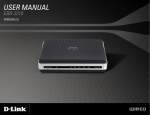
The D-Link DSL-520B is an ADSL2+ modem that offers the convenience of Ethernet connections. This user manual provides a simple and easy-tounderstand format to install and configure your modem.
Package Contents
• ADSL2+ Modem
• 12VDC, 500mA DC CEC-compliant switching power adapter
• RJ-11 telephone cable
• RJ-45 Ethernet cable
• Quick Install Guide
• Installation CD-ROM
Note: Using a power supply with a different voltage rating than the one included with the DSL-520B will cause damage and void the warranty for this product.
Important Safety Instructions
• Place your modem on a flat surface close to the cables in a location with sufficient ventilation.
• To prevent overheating, do not obstruct the ventilation openings of this equipment.
• Plug this equipment into a surge protector to reduce the risk of damage from power surges and lightning strikes.
• Operate this equipment only from an electrical outlet with the correct power source as indicated on the adapter. • Do not open the cover of this equipment. Opening the cover will void any warranties on the equipment.
• Unplug equipment first before cleaning. A damp cloth can be used to clean the equipment. Do not use liquid/aerosol cleaners or
magnetic/static cleaning devices.
• To reduce the risk of fire, use only No. 26 AWG (or larger diameter/smaller AWG) RJ-11 telephone cable.
D-Link DSL-520B ADSL2+ Modem User Manual
4
Section 1 - General Information
Front Panel View
4
1
2
3
• A solid green light indicates the unit is powered on.
• A red light indicates a malfunction.
1
Power LED
2
LAN LED
• A solid light indicates a connection to an Ethernet-enabled computer. This LED
blinks during data transmission.
DSL LED
• A solid light indicates the DSL is synchronized
• A flashing LED indicates the modem is attempting to synchronize with the DSL
provider.
3
• A solid green light indicates that the modem has an IP address and is connected
to the Internet.
4
Internet LED
• A red light indicates that the modem does not have an IP address or authentication
has failed
• No light indicates that an ADSL connection is not present or the modem is in
bridge mode.
D-Link DSL-520B ADSL2+ Modem User Manual
5
Section 1 - General Information
Rear Panel View
1
2
3
4
5
1
2
DSL Line
• Connect to an active telephone line (RJ-11).
LAN Port
• Connect Ethernet devices such as computers, switches, and hubs.
3
Reset
4
5
ON/OFF
Power Receptor
D-Link DSL-520B ADSL2+ Modem User Manual
• Pressing the Reset button for 5 seconds restores the modem to its original factory
default settings.
• Press this button to turn the unit ON or OFF.
• Receptor for the supplied power adapter.
6
Section 2 - Installing The Modem
Installing the Modem
Connect the ADSL and Telephone Lines
• Connect an RJ-11 cable between the wall phone jack and the DSL port on the rear panel of the modem.
Connect the PC to the Modem
• To use the Ethernet connection, connect the Ethernet cable from the computer directly to the modem. Connect one end of the
Ethernet cable to the port labeled LAN on the back of the modem and attach the other end to the Ethernet port of your computer.
• If your LAN has more than one computer, you can attach one end of an Ethernet cable to a hub or a switch and the other to the
Ethernet port (labeled LAN) on the modem. Note that either a crossover or straight-through Ethernet cable can be used. The
modem automatically recognizes the type of connection that is required.
D-Link DSL-520B ADSL2+ Modem User Manual
7
Section 2 - Installing The Modem
Connect the Power Adapter
• Complete the process by connecting the supplied 12V, 500mA power adapter to the POWER connector on the back of the device
and plug the adapter into a wall outlet or power strip. Then turn on and boot up your PC and any LAN devices, such as hubs or
switches, and any computers connected to them.
D-Link DSL-520B ADSL2+ Modem User Manual
8
Section 3 - Installation Diagram
Installation Diagram
DSL-520B Modem
Desktop Computer
LAN
D-Link DSL-520B ADSL2+ Modem User Manual
LAN
RESET ON/OFF
5V - - - 3A
9
Section 4 - Configuring Your Computer
Configuring Your Computer
Prior to accessing the modem through the LAN or USB port, note the following necessary configurations:
• Your PC’s TCP/IP address: 192.168.1.x (where “x” is any number between 2 and 254)
• The modem’s default IP address: 192.168.1.1
• Subnet mask: 255.255.255.0
Below are the procedures for configuring your computer. Follow the instructions for the operating system that you are using.
Windows® XP
1. In the Windows taskbar, click on the Start button then go to Control Panel and then click Network Connections.
2. In the Network Connections window, right-click on the Local Area Connection icon and click on Properties.
3. Listed in the Local Area Connection window are the installed network components. Make sure the box for Internet Protocol (TCP/
IP) is checked and then click on Properties.
4. In the Internet Protocol (TCP/IP) Properties dialog box, click on the radio buttons labeled Obtain an IP address automatically and
Obtain DNS server address automatically.
5. Click on OK twice to save your changes and then close the Control Panel.
D-Link DSL-520B ADSL2+ Modem User Manual
10
Section 6 - Quick Setup
Mac
These are instructions for configuring your Mac OS X operating system
1.
2.
3.
4.
5.
In the Mac OS X Dock, click on the System Preferences icon.
Under Internet & Network, click Network. In the Show menu, select Built-in Ethernet or Ethernet (Depending on your Mac OS version.)
Click the TCP/IP tab.
In the Configure menu, select Using DHCP.
Click Apply Now and Save if your computer prompts you to save changes.
D-Link DSL-520B ADSL2+ Modem User Manual
11
Section 6 - Quick Setup
Log in to the Modem
This section will explain how to log in to your modem using the following steps:
1. Launch your web browser.
2. Enter the URL http://192.168.1.1 in the address bar and press Enter.
A login screen like the one below will be displayed after you connect to the user interface.
Note: Use admin/admin as a default for
username and password.
• The admin account can perform all
functions
(username / password: admin / admin).
Note: Passwords can be changed at any
time.
3. Enter your user name and password, and then click OK to display the user interface.
Note: This manual has been prepared using the admin user name.
D-Link DSL-520B ADSL2+ Modem User Manual
12
Section 6 - Quick Setup
Quick Setup
Quick Setup will be the first page you see when you log in to the router. Verify the box is checked next to DSL Auto-connect. Please prepare your
account information provided by your Internet Service Provider (ISP).
Click Next to begin setup.
Note: Quick Setup will allow you to configure a PPPoE
connection. For more information on PPPoE and other
connection types, please see the Advanced Setup section
in this user manual.
D-Link DSL-520B ADSL2+ Modem User Manual
13
Section 6 - Quick Setup
The router will automatically perform a PVC scan in order to detect your DSL connection.
If the scan is unsuccessful, you must manually enter account settings. For these settings, please refer to your account information provided by
your ISP.
D-Link DSL-520B ADSL2+ Modem User Manual
14
Section 6 - Quick Setup
When the PVC scan is complete, you will be prompted to enter your username and password as provided by your ISP. Advanced users can configure optional settings on this page.
Click Next to continue setup.
D-Link DSL-520B ADSL2+ Modem User Manual
15
Section 6 - Quick Setup
The router will automatically verify your username and password.
D-Link DSL-520B ADSL2+ Modem User Manual
16
Section 6 - Quick Setup
This page allows you to adjust the Local Area Network settings. No changes are required on this page. Click Next to continue.
D-Link DSL-520B ADSL2+ Modem User Manual
17
Section 6 - Quick Setup
Verify your settings are correct and click Save/Reboot. The router will save your settings and reboot itself. Please do not unplug any cables during
this process.
D-Link DSL-520B ADSL2+ Modem User Manual
18
Section 7 - Device Info
Device Info
The Device Info page shows details of the modem such as the version of the software, bootloader, LAN IP address, etc. It also displays the current
status of your DSL connection.
Summary
A summary of your device’s information is provided in this section. The information will reflect your DSL’s connection status.
D-Link DSL-520B ADSL2+ Modem User Manual
19
Section 7 - Device Info
WAN
The WAN Info screen displays WAN connections previously set up in the Home section. There is an extra “Status” column used for connection status
information, displaying either ADSL Link Down or ADSL Link Up.
D-Link DSL-520B ADSL2+ Modem User Manual
20
Section 7 - Device Info
Statistics
LAN
The LAN section shows received and transmitted packet information
for the Ethernet interface. Click on Reset Statistics to renew the
information.
WAN
The WAN section shows received and transmitted packet information
for the WAN connections that you have set up. Click on Reset
Statistics to renew the information.
D-Link DSL-520B ADSL2+ Modem User Manual
21
Section 7 - Device Info
ATM
The ATM section displays statistical values for your ATM interface as well as for AAL5 and AAL5 VCC. Click on Reset Statistics to reset the values.
D-Link DSL-520B ADSL2+ Modem User Manual
22
Section 7 - Device Info
ADSL
Information contained in the ADSL screen is useful for troubleshooting and diagnosing connection problems.
D-Link DSL-520B ADSL2+ Modem User Manual
23
Section 7 - Device Info
Route
The Route Info section displays route information showing the IP addresses of the destination, gateway, and subnet mask as well as other route
information.
D-Link DSL-520B ADSL2+ Modem User Manual
24
Section 7 - Device Info
ARP
This section allows you to query the MAC and IP address information of the equipment attached to the modem.
D-Link DSL-520B ADSL2+ Modem User Manual
25
Section 7 - Device Info
DHCP
The DHCP server is enabled by default for the router’s Ethernet LAN interface. DHCP service will supply IP settings to computers configured to
automatically obtain IP settings that are connected to the router though the Ethernet port. When the router is used for DHCP it becomes the default
gateway for DHCP client connected to it. Keep in mind that if you change the IP address of the router, you must change the range of IP addresses
in the pool used for DHCP on the LAN.
D-Link DSL-520B ADSL2+ Modem User Manual
26
Section 9 - Advanced Setup
Advanced Setup
This section of the setup is an advanced version of the quick setup. If you want to make specific configurations to your modem such as creating a
SNMP, etc., consider going through this advanced setup for a more comprehensive configuration.
WAN
Configure the DSL settings as provided by your ISP.
Click the Add button if you want to add a new connection
for the WAN interface and to proceed to the ATM PVC
Configuration screen on the following page. The ATM PVC
Configuration screen allows you to configure an ATM PVC
identifier (VPI and VCI) and select a service category.
D-Link DSL-520B ADSL2+ Modem User Manual
27
Section 9 - Advanced Setup
ATM PVC Configuration
VPI/VCI: These values are required for all DSL connection types and are provided by your ISP.
Service Category: Use the default setting unless otherwise instructed by your ISP.
Enable QoS: Use the default setting unless otherwise instructed by your ISP. For more information about QoS, see the Quality of Service section
in this user manual.
Click Next
D-Link DSL-520B ADSL2+ Modem User Manual
28
Section 9 - Advanced Setup
Connection Type
This screen shows the types of network protocols and encapsulation modes that can be configured.
Connection Type: Select the connection type that your ISP has instructed to use. • PPP over ATM (PPPoA)
• PPP over Ethernet (PPPoE)
• MAC Encapsulation Routing (MER)/DHCP
• IP over ATM (IPoA)
• Bridging
PPPoE, MER (also referred to as DHCP) and
Bridging are the most common connection types
in North America. To set up a PPPoE, MER or
Bridging connection, follow the instructions on
the following pages of this user manual. PPPoA
and IPoA are more widely utilized in other regions.
Setup for PPPoA and IPoA are similar to PPPoE and
MER, respectively.
Encapsulation Mode: Use the default setting
unless otherwise instructed by your ISP.
Note: These settings are ISP dependant. For
information regarding proper configuration, contact
your ISP.
D-Link DSL-520B ADSL2+ Modem User Manual
29
Section 9 - Advanced Setup
PPP over Ethernet (PPPoE)
This page allows you to configure your PPPoE connection.
PPP Username: Enter your username as provided by
your ISP.
PPP Password: Enter your password as provided by
your ISP.
PPP Service Name: Enter any name that will help you
identify your connection. This field will not affect your
connection.
Dial on demand (with idle timeout timer): Allows
you to manually connect to the Internet so you are not
permanently connected. Idle timeout timer is included.
PPP IP extension: Used by some ISPs. Check with your
ISP to see if it is required.
Use Static IP Address: Select if your ISP has provided
you with a static IP address. If selected, you will be asked
to enter the static IP address.
Retry PPP password on authentication error: Select if you want the router to automatically retry your PPP username and password when there
is an authentication error on your DSL line.
Enable PPP Debug Mode: Select if you want to keep a log of connection negotiation transactions. This option is used for troubleshooting connection
issues.
Bridge PPPoE Frames Between WAN and Local Ports (Default Enabled): Use the default setting unless otherwise instructed by your ISP.
MTU: Use the default setting of 1492 unless otherwise instructed by your ISP.
Click Next.
D-Link DSL-520B ADSL2+ Modem User Manual
30
Section 9 - Advanced Setup
Network Address Translation Settings (PPPoE)
Enable NAT: Select if you would like to share your internet connection. Sharing your connection may also require an Ethernet switch to connect
multiple computers.
Enable Firewall: Select if you would like to utilize the firewall to help protect you from unwanted internet threats.
Enable IGMP Multicast: Use the default setting unless otherwise instructed by your ISP.
Enable WAN Service: This option is Enabled by default. Deselecting this option will cause your DSL connection to be disabled.
Service Name: Enter any name that will help you identify your connection. This field will not affect your connection.
Click Next.
D-Link DSL-520B ADSL2+ Modem User Manual
31
Section 9 - Advanced Setup
WAN Setup – Summary (PPPoE)
Confirm the settings on this page match the settings provided by your ISP. To make any changes, click Back.
If your settings are correct, click Save.
Note: After clicking Save, you will have to reboot the modem in order to activate your connection.
D-Link DSL-520B ADSL2+ Modem User Manual
32
Section 9 - Advanced Setup
MAC Encapsulation Routing (MER) or DHCP
This page allows you to configure your MER/DHCP connection.
Obtain an IP address automatically: This is the default option. If your ISP has provided you with a static IP address, select Use the following IP
address. Enter the IP address and Subnet Mask that your ISP has provided.
Obtain default gateway automatically: This is the default option. If your ISP has provided you with a static default gateway, select Use the following
default gateway. Select Use IP Address and enter the default gateway that your ISP has provided. Alternately, you may choose to select Use WAN
Interface.
Obtain DNS server addresses automatically: This is the default option. If your ISP has provided you with static DNS server addresses, select Use
the following DNS server addresses. Enter the Primary and Secondary (if available) DNS server addresses that you ISP has provided.
Click Next.
D-Link DSL-520B ADSL2+ Modem User Manual
33
Section 9 - Advanced Setup
Network Address Translation Settings (MER/DHCP)
Enable NAT: Select if you would like to share your internet connection. Sharing your connection may also require an Ethernet switch to connect
multiple computers.
Enable Firewall: Select if you would like to utilize the firewall to help protect you from unwanted Internet threats.
Enable IGMP Multicast: Use default setting unless otherwise instructed by your ISP.
Enable WAN Service: This option is Enabled by default. Deselecting this option will cause your DSL connection to be disabled.
Service Name: Enter any name that will help you identify your connection. This field will not affect your connection.
Click Next.
D-Link DSL-520B ADSL2+ Modem User Manual
34
Section 9 - Advanced Setup
WAN Setup – Summary (MER/DHCP)
Confirm the settings on this page match the settings provided by your ISP. To make any changes, click Back.
If your settings are correct, click Save.
Note: After clicking Save, you will have to reboot the modem in order to activate your connection.
D-Link DSL-520B ADSL2+ Modem User Manual
35
Section 9 - Advanced Setup
Bridging
Enable WAN Service: This option is Enabled by default. Deselecting this option will cause your DSL connection to be disabled.
Service Name: Enter any name that will help you identify your connection. This field will not affect your connection.
Click Next.
D-Link DSL-520B ADSL2+ Modem User Manual
36
Section 9 - Advanced Setup
WAN Setup – Summary (Bridging)
Confirm the settings on this page match the settings provided by your ISP. To make any changes, click Back.
If your settings are correct, click Save.
Note: After clicking Save, you will have to reboot the modem in order to activate your connection.
D-Link DSL-520B ADSL2+ Modem User Manual
37
Section 7 - Device Info
LAN
You can configure the DSL Modem IP address and Subnet
Mask for the LAN interface.
The Save button only saves the LAN configuration data,
but does not apply the configurations. Select the Save/
Reboot button to save the LAN configuration data, then
reboot the modem and apply the new configuration.
D-Link DSL-520B ADSL2+ Modem User Manual
38
Section 7 - Device Info
NAT
Note: You must enable the NAT service when you configure the WAN connection at first, the NAT item appears in the Advanced Setup
directory. In the pure bridging mode, there is no NAT service.
Overview - Setting up the NAT Function
The DSL router is equipped with the network address translation (NAT) function. With address mapping, several users in the
local network can access the Internet via one or more public IP addresses. All the local IP addresses are assigned to the public
IP address of the router by default.
One of the characteristics of NAT is that data from the Internet is not allowed into the local network unless it is explicitly
requested by one of the PCs in the network. Most Internet applications can run behind the NAT firewall without any problems.
For example, if you request Internet pages or send and receive e-mails, the request for data from the Internet comes from a PC
in the local network, and so the router allows the data to pass through. The router opens one specific port for the application.
A port in this context is an internal PC address, via which the data is exchanged between the Internet and a client on a PC in
the local network. Communicating via a port is subject to the rules of a particular protocol (TCP or UDP).
If an external application tries to send a call to a PC in the local network, the router blocks it. There is no open port via which
the data could enter the local network. Some applications, such as games on the Internet, require several links (that is, several
ports), so that players can communicate with each other. In addition, these applications must also be permitted to send requests
from other users on the Internet to users in the local network. These applications cannot run if NAT is activated.
D-Link DSL-520B ADSL2+ Modem User Manual
39
Section 7 - Device Info
Using port forwarding (the forwarding of requests to particular ports), the router is forced to send requests from the Internet
for a certain service, for example, a game, to the appropriate port(s) on the PC on which the game is running. Port triggering
is a special variant of port forwarding. Unlike port forwarding, the DSL router forwards the data from the port block to the PC
which has previously sent data to the Internet via a certain port (trigger port). This means that approval for the data transfer
is not tied to one specific PC in the network, but rather to the port numbers of the required Internet service.
Where configuration is concerned, you must define a so-called trigger port for the application and also the protocol (TCP or
UDP) that this port uses. You then assign the public ports that are to be opened for the application to this trigger port. The
router checks all outgoing data for the port number and protocol. If it identifies a match of port and protocol for a defined
trigger port, then it opens the assigned public ports and notes the IP address of the PC that sent the data. If data comes back
from the Internet via one of these public ports, the router allows it to pass through and directs it to the appropriate PC. A trigger
event always comes from a PC within the local network. If a trigger port is addressed from outside, the router simply ignores it.
Note:
• An application that is configured for port triggering can only be run by one user in the local network at a time.
• After public ports are opened, they can be used by unauthorized persons to gain access to a PC in the local network.
• When the DSL router is supplied, the NAT function is activated. For example, all IP addresses of PCs in the local network are converted
to the public IP address of the router when accessing the Internet. You can use NAT settings to configure the DSL router to carry out
the following tasks.
• For functions described as follows, IP addresses of the PCs must remain unchanged. If the IP addresses of the PCs are assigned via
the DHCP server of the DSL router, you must disable DHCP server as the settings in the local network menu entry for the lease time
or assign static IP addresses for the PCs.
• You can enable or disable the NAT function. By default, the NAT function is enabled.
D-Link DSL-520B ADSL2+ Modem User Manual
40
Section 7 - Device Info
NAT - Virtual Server Setup
By default, DSL router blocks all external users from connecting to or communicating with your network. Therefore, the system
is safe from hackers whom may try to intrude into the network and damage it.
However, you may want to expose your network to the Internet in limited and controlled ways in order to enable some
applications to work from the LAN (for example, game, voice, and chat applications) and to enable Internet access to servers
in the home network. The port forwarding feature supports both functions. This topic is also referred as Local Servers.
The port forwarding page is used to define applications that require special handling by DSL router. All you need to do is to
select the application protocol and the local IP address of the computer that is using or providing the service. If required, you
may add new protocols in addition to the most common ones provided by DSL router.
For example, if you wanted to use a file transfer protocol (FTP) application on one of your PCs, you would simply select FTP
from the list and enter the local IP address or host name of the designated computer. All FTP-related data arriving at DSL router
from the Internet henceforth is forwarded to the specific computer.
Similarly, you can grant Internet users access to servers inside your home network, by identifying each service and the PC that
provide it. This is useful, for example, if you want to host a Web server inside your home network. When an Internet user points
his/her browser to DSL router external IP address, the gateway forwards the incoming HTTP request to your Web server. With
one external IP address (DSL router main IP address), different applications can be assigned to your LAN computers, however
each type of application is limited to use one computer.
For example, you can define that FTP uses address X to reach computer A and Telnet also uses address X to reach omputer A.
But attempting to define FTP to use address X to reach both computer A and B fails. DSL router, therefore, provides the ability
to add additional public IP addresses to port forwarding rules, which you must obtain from your ISP, and enter into the IP
addresses pool. Then, you can define FTP to use address X to reach computer A and address Y to reach computer B.
D-Link DSL-520B ADSL2+ Modem User Manual
41
Section 7 - Device Info
Additionally, port forwarding enables you to redirect traffic to a different port instead of the one to which it was designated.
For example, if you have a Web server running on your PC on port 8080 and you want to grant access to this server to any one
who accesses DSL router via HTTP. To accomplish this, do as follows:
Step 1
Define a port forwarding rule for the HTTP service, with the PC IP or host name.
Step 2
Specify 8080 in the Forward to Port field.
All incoming HTTP traffic is forwarded to the PC running the Web server on port 8080. When setting a port forwarding service,
ensure that the port is not used by another application, which may stop functioning. A common example is when using SIP
signaling in Voice over IP, the port used by the gateway VoIP application (5060) is the same port, on which port forwarding is
set for LAN SIP agents.
Note: Some applications, such as FTP, TFTP, PPTP and H323, require the support of special specific application level gateway (ALG)
modules in order to work inside the home network. Data packets associated with these applications contain information that allows
them to be routed correctly. An ALG is needed to handle these packets and ensure that they reach their intended destinations. DSL
router is equipped with a robust list of ALG modules in order to enable maximum functionality in the home network. The ALG is
automatically assigned based on the destination port.
Virtual servers are configured for this purpose.
D-Link DSL-520B ADSL2+ Modem User Manual
42
Section 7 - Device Info
Port Triggering
If you configure port triggering for a certain application, you must determine a so-called trigger port and the protocol (TCP
or UDP) that this port uses. You then assign the public ports that are to be opened for the application to this trigger port. You
can select known Internet services or manually assign ports or port blocks.
D-Link DSL-520B ADSL2+ Modem User Manual
43
Section 7 - Device Info
DMZ Host
The demilitarized (DMZ) host feature allows one local computer to be exposed to the Internet. This function is applicable for:
• Users who want to use a special-purpose Internet service, such as an on-line game or video conferencing program, that is
not in the port forwarding list and for which no port range information is available.
• Users who are not concerned with security and wish to expose one computer to all services without restriction.
Note: A DMZ host is not protected by the firewall and may be vulnerable to attack. This may also put other computers in the home
network at risk. Hence, when designating a DMZ host, you must consider the security implications and and take the appropriate
precautions.
You can set up a client in your local network as a DMZ host. Your device then forwards all incoming data traffic from the
Internet to this client. You can, for example, operate your own Web server on one of the clients in your local network and make
it accessible to Internet users. As the exposed host, the local client is directly visible to the Internet and therefore particularly
vulnerable to attacks (for example, hacker attacks). Enable this function only when necessary (for example, to operate a Web
server) and when other functions (for example, port forwarding) are inadequate. In this case, you should take appropriate
measures for the clients concerned.
Note: Only one PC per public IP address can be set up as an exposed host.
D-Link DSL-520B ADSL2+ Modem User Manual
44
Section 7 - Device Info
Security
IP Filtering
Click Security > IP Filtering and the following interface appears. By default, the firewall is enabled. The firewall is used to block
document transmissions between the Internet and your PC. It serves as a security gate and permits only authorized traffic to
be sent to the LAN.
Note: If the modem is configured to bridge mode only, IP filtering is disabled and the IP filtering interface does not appear.
If the modem does not configure a PVC of Bridge mode, MAC filtering is disabled and the MAC Filtering interface does not
appear.
D-Link DSL-520B ADSL2+ Modem User Manual
45
Section 7 - Device Info
Outgoing
Click Security > IP Filtering > Outgoing and the following page will appear.
By default, all outgoing IP traffic from LAN is allowed, but some IP traffic can be blocked by setting up filters.
Click Add and the page for defining the IP filtering rule appears. In this page, you can create a filter rule to identify outgoing
IP traffic by specifying a new filter name and at least one condition. All specified conditions in the filtering rule must comply
with the rule to take effect.
Click Save/Apply to save and activate the filter.
D-Link DSL-520B ADSL2+ Modem User Manual
46
Section 7 - Device Info
Incoming
Click Security > IP Filtering > Incoming.
By default, all incoming IP traffic from the WAN is blocked when the firewall is enabled. However, some IP traffic can be accepted
by setting up filters.
Click Add, the following page appears. In this page, you can create a filter rule to identify incoming IP traffic by specifying a
new filter name and at least one condition. All specified conditions in this filter rule must comply with the rule. Click Save/
Apply to save and activate the filter.
You should select at least one WAN interface to apply this rule.
D-Link DSL-520B ADSL2+ Modem User Manual
47
Section 7 - Device Info
MAC Filtering
Click Security > MAC Filtering.
MAC Filtering is only effective on ATM PVCs configured in Bridge mode. Forwarded means that all MAC layer frames are
forwarded except those matching any of the specified rules in the following table. Blocked means that all MAC layer frames
are blocked except those matching with any of the specified rules in the following table.
Click Change Policy and the following page will appear. Then you can change the MAC Filtering Global Policy from FORWARDED
to BLOCKED.
Read the warning information. Click Yes to change the MAC filtering global policy from Forwarded to Blocked. Click No to cancel.
D-Link DSL-520B ADSL2+ Modem User Manual
48
Section 7 - Device Info
Parental Control
Click Security > Parental Control.
Click Add and the following page will appear.
On this page, you can add time of day restriction to a particular LAN device connected to the Router. The Browser’s MAC Address
automatically displays the MAC address of the LAN device where the browser is running. To restrict other LAN device, click
Other MAC Address and enter the MAC address of the another LAN device. To obtain the MAC address of a Windows based
PC, enter ipconfig /all in the DoS window.
D-Link DSL-520B ADSL2+ Modem User Manual
49
Section 9 - Advanced Setup
Quality of Service
Many communication and multimedia applications require large, high-speed bandwidths to transfer data between the local network and the internet.
However, for many applications there is often only one internet connection available with limited capacity. QoS divides this capacity between the
different applications and provides undelayed, continuous data transfer in situations where data packets with higher priority are given preference.
Click Quality of Service and the following page will appear. Under Quality of Service, there are two network share modes: Queue Config and QoS
Classification.
Network QoS is an industry-wide set of standards and mechanisms for ensuring high-quality performance for critical applications. By using QoS
mechanisms, network administrators can use existing resources efficiently and ensure the required level of service without reactively expanding
or over-provisioning their networks.
Traditionally, the concept of quality in networks meant that all network traffic was treated equally. The result was that all network traffic received
the network’s best effort, with no guarantees for reliability, delay, variation in delay, or other performance characteristics. With best-effort delivery
service, however, a single bandwidth-intensive application can result in poor or unacceptable performance for all applications. The QoS concept
of quality is one in which the requirements of some applications and users are more critical than others, which means that some traffic needs
preferential treatment.
D-Link DSL-520B ADSL2+ Modem User Manual
50
Section 9 - Advanced Setup
Enabling QoS
In this page, you can perform QoS queue management configuration. By default, the system enables QoS and sets a default DSCP mark to automatically
mark incoming traffic without reference to particular classifier.
Select Advanced Setup > Quality of Service and the following page will appear.
Select Enable QoS to enable QoS and set the default DSCP mark. Click Save/Apply to activate QoS.
D-Link DSL-520B ADSL2+ Modem User Manual
51
Section 9 - Advanced Setup
QoS Configuration
The queuing in packet QoS goes into effect only when a packet is forwarded to a QoS-enabled PVC. Packet forwarding
is determined by IP routing or bridging, not under control of the packet QoS.
Click Queue Config, and the following page will appear. In this page, you
can configure QoS queue. A maximum of 16 entries can be configured.
QoS Queue Configuration can allocate four queues. Each of the queues
can be configured for a precedence value (Lower integer values for
precedence imply higher priority for this queue relative to others). The
queue entry configured is used by the classifier to place ingress packets
appropriately.
Note: Lower integer values for precedence imply higher priority for this
queue relative to others.
For example, add a QoS queue entry and allocate it to a specific network
interface (PVC 0/0/35). Set integer values for queue precedence to 1.
D-Link DSL-520B ADSL2+ Modem User Manual
52
Section 9 - Advanced Setup
Step 1
Click Add, and the following page will appear.
Queue Configuration Status: set to enable or disable
a QoS queue.
Queue: Select a specific network interface. When you
have already selected a network interface, the specific
network interface selected automatically allocates to
the queue.
Queue Precedence: Select an integer value for queue
precedence. After you select an integer value, the queue
entry appropriately places to ingress packets. Lower
integer values for precedence imply higher priority for
this queue relative to others.
Step 2
Add a QoS queue entry and assign it to a specific network interface (PVC 0/0/35), and set integer values for queue precedence
to 1. See the following figure:
Step 3
After proper modifications, click Save/Apply and the following page will appear. This configuration takes effect immediately.
To delete a certain queue, disable it, select it, and then click Remove. After the queue is configured, you can create several
traffic class rules to classify the upstream traffic.
D-Link DSL-520B ADSL2+ Modem User Manual
53
Section 9 - Advanced Setup
QoS Classification
Some applications require specific bandwidth to ensure its data be forwarded in time. QoS classification can creates traffic class rule to classify
the upstream traffic. Assign queue which defines the precedence and the interface and optionally overwrite the IP header DSCP byte. After QoS
classification, QoS divides capacity between different applications and provides undelayed, continuous data transfer where data packet with higher
priority is given preference.
Click QoS Classification and the following page will appear.
In this page, you can configure network traffic classes.
Click Add to continue.
D-Link DSL-520B ADSL2+ Modem User Manual
54
Section 9 - Advanced Setup
Traffic Class Name: Enter a name of the class.
Rule Order: Select order for queue.
Rule Status: Enable or disable this traffic class rule.
Assign Classification Queue: Select a classification queue.
Assign Differentiated Service Code Point (DSCP) Mark:
Select a mark service that modifies the original packet IP
header if all rules defined within the classification class are
matched.(CS-Mark IP Precedence, AF-Assured Forwarding,
EF-Expedited
Forwarding)
Mark 802.1p if 802.1q is Enabled: Select an 802.1p priority
number that serves as the 802.1p value.
There are two sets of classification rules. Set-1 is based on
different fields within TCP/UDP/IP layer plus physical LAN
port. Set-2 is based on MAC layer IEEE 802.1p priority field.
Set-1 Rules contain the following:
Physical LAN Port: Select one among Ethernet ports and
D-Link DSL-520B ADSL2+ Modem User Manual
55
Section 9 - Advanced Setup
wireless port.
Protocol: Select one among TCP/UDP TCP UDP or ICMP protocols.
Source IP Address
Source Subnet Mask
UPD/TCP Source Port
Destination IP Address
Destination Subnet Mask
UPD/TCP Destination Port or a Range of Ports
Source Mac Address
Source Mac Mask
Destination Mac Address
Destination Mac Mask
Set-2 Rules contain the following:
802.1p Priority: the 802.1p header includes a 3-bit prioritization field, which allows packets to be grouped into eight
levels of priority (0-7), where level 7 is the highest one.
D-Link DSL-520B ADSL2+ Modem User Manual
56
Section 9 - Advanced Setup
QoS-DSCP Setting
In order to understand Differentiated Services Code Point (DSCP), you should be familiar with the differentiated services model (Diffserv).
Diffserv is a Class of Service (CoS) model that enhances best-effort Internet services by differentiating individual user traffic, service requirements
and other criteria. Packets are specifically marked, allowing network nodes to provide different levels of service via priority queuing or bandwidth
allocation, or by choosing dedicated routes for
specific traffic flows.
As displayed in following diagram, the IPV4 packet has a TOS field. Diffserv defines TOS field in IP packet headers
referred to as DSCP. Hosts or routes that pass traffic to a Diffserv-enabled network typically mark each transmitted
packet with an appropriate DSCP. The DSCP markings are used by Diffserv network routers to appropriately
classify packets and to apply particular queue handing or scheduling behavior.
D-Link DSL-520B ADSL2+ Modem User Manual
57
Section 9 - Advanced Setup
Routing
Default Gateway
In this page, you can modify the default gateway
settings. If you select Enable Automatic Assigned
Default Gateway, this router can accept the first received
default gateway assignment from one of the PPPoA,
PPPoE or MER/DHCP enabled PVC(s). If the check box is
not selected, you must enter the static default gateway
and/or a WAN interface. Then, click Save/Apply.
Note: If the Automatic Assigned Default Gateway check
box is changed from deselected to selected, you must
reboot the router to obtain the automatic assigned
default gateway.
D-Link DSL-520B ADSL2+ Modem User Manual
58
Section 9 - Advanced Setup
Static Route
In this page you can modify the static route settings. You
can query the preset static routes, delete an existing static
route, or add a new static route. By default, the system has
no static route information.
Destination: The IP address to which packets are
transmitted.
Subnet Mask: The subnet mask of the destination IP
address.
Gateway: The gateway that the packets pass by during
transmission.
Interface: The interface that the packets pass through
on the
modem.
Click Add and the following page will appear. Enter the
destination network address, subnet mask, gateway AND/
OR available WAN interface, then click Save/Apply to add
the entry to the routing table.
D-Link DSL-520B ADSL2+ Modem User Manual
59
Section 9 - Advanced Setup
RIP
To activate RIP for the device, select the Enabled radio button for Global RIP Mode. To configure an individual interface, select
the desired RIP version and operation, followed by placing a check in the Enabled checkbox for the interface. Click the Save/
Apply button to save the configuration, and to start or stop RIP based on the Global RIP mode selected.
D-Link DSL-520B ADSL2+ Modem User Manual
60
Section 9 - Advanced Setup
DNS
Server Configuration
In this page, you can modify the DNS server settings. If Enable Automatic Assigned DNS is selected, this router accepts the first received DNS
assignment from one of the PPPoA, PPPoE or MER/DHCP enabled PVC(s) during the connection establishment. If the checkbox is not selected, enter
the primary and secondary (optional) DNS server IP addresses. The interface is as follows. Click Save to save the new configuration.
Note: You must reboot the router to make the new configuration take effect.
D-Link DSL-520B ADSL2+ Modem User Manual
61
Section 9 - Advanced Setup
Dynamic DNS
In this interface, you can modify the Dynamic DNS settings.
The Dynamic DNS service allows you to alias a dynamic IP address
to a static hostname in any of the many domains, allowing your
DSL router to be more easily accessed from various locations on
the Internet.
Click Add to add Dynamic DNS
Add dynamic DNS
Enter your information in the spaces provided and click Save.
D-Link DSL-520B ADSL2+ Modem User Manual
62
Section 9 - Advanced Setup
DSL
The DSL settings page contains modulation and capability settings.
Consult your ISP to determine the correct settings. Click Apply if you
are finished or click on Advanced Settings if you want to configure
other advanced settings.
D-Link DSL-520B ADSL2+ Modem User Manual
63
Section 9 - Advanced Setup
Advanced Settings
The test mode can be selected from the ADSL Advanced Settings page.
Test modes include normal, reverb, medley, no retrain, and L3. After you
make your selection, click on Apply to save these settings first before
you go to Tone Selection.
The frequency band of ADSL is split into 256 separate tones, each
spaced 4.3125 kHz apart. Each tone carries separate data, so the modem
operates as if 256 separate modems were running in parallel. The tone
range is from 0 to 31 for upstream and from 32 to 255 for downstream.
Do not change these settings unless directed by your ISP.
D-Link DSL-520B ADSL2+ Modem User Manual
64
Section 9 - Advanced Setup
MAC Clone
This page allosw you to clone the MAC address on your router. This is needed when adding a router to your network in order to share your internet
connection.
D-Link DSL-520B ADSL2+ Modem User Manual
65
Section 10 - Diagnostics
Diagnostics
The diagnostics screen allows you to run diagnostic tests to check your DSL connection. The results will show test results of two connections:
• Connection to your local network
• Connection to your DSL service provider
Click Run Diagnostic Tests to begin.
D-Link DSL-520B ADSL2+ Modem User Manual
66
Section 11 - Management
Management
Settings
Backup
The Backup Settings button allows you to save your router configuration to a file on your computer so that it may be accessed
again later. This feature is useful if you have changed the configuration on the router, but would like to revert to a previous
configuration.
To save your current configuration, click the Backup Settings button. The following pop-up screen will appear with a prompt
to open or save the file to your computer.
D-Link DSL-520B ADSL2+ Modem User Manual
67
Section 11 - Management
Update
To load a previously saved configuration file onto your router, click Browse, select the file on your computer and then click on
Update Settings.
The router will restore settings and reboot to activate the restored settings.
D-Link DSL-520B ADSL2+ Modem User Manual
68
Section 11 - Management
Restore Default
Restore Default Settings will delete all current settings and restore the router to factory default settings. Click on the Restore
Default Settings button to proceed. The following confirmation dialog will appear confirming your decision to restore default
settings. Click on OK to continue.
D-Link DSL-520B ADSL2+ Modem User Manual
69
Section 11 - Management
System Log
Click View System Log to show the following interface. The system log dialog allows you to view the system log and configure the system log options.
Click Configure System Log to show the following interface. You can enable or disable the system log and then select the Log Level, Display Level
and Mode, and click Apply to end your configurations.
Both the log level and display level have eight choices. The default log level is Debugging and the default display level is Error. The mode options
are Local, Remote, and Both. The default is Local.
If you select Remote or Both, all events are transmitted to the
specified UDP port of the specified log server.
D-Link DSL-520B ADSL2+ Modem User Manual
70
Section 11 - Management
System Log Configuration
From the configuration screen, set the log to Enable, select the Log Level, Display Level and Mode. If the selected mode is “Remote” or “Both”, events
will be sent to a specified IP address and UDP port of a remote system log server. If the selected mode is “Local” or “Both”, events will be recorded
and viewed locally. Select the desired values and click Apply to save the system log options.
D-Link DSL-520B ADSL2+ Modem User Manual
71
Section 11 - Management
TR-069 Client
WAN Management Protocol (TR-069) allows a Auto-Configuration Server (ACS) to perform auto-configuration, provision, collection and diagnostics
to this device.
If you wish to enable this protocol, then select enable. Contact your ISP to determine the ACS URL, ACS User Name, and ACS Password. You must
click on the Save/Reboot button for the change to take place.
D-Link DSL-520B ADSL2+ Modem User Manual
72
Section 11 - Management
Internet Time
The Time Settings page allows you to automatically synchronize your time with a time server on the Internet. To set the modem’s time, click on the
automatically synchronize with Internet time servers checkbox. Additional time settings will appear below the checkbox.
Select from the list of NTP (Network Time Protocol) time servers. Then select the time zone that you are in and click Apply to save.
D-Link DSL-520B ADSL2+ Modem User Manual
73
Section 11 - Management
Access Control—Services
From this page you can enable/disable certain services from passing through your modem. Services that can be enabled/disabled on the LAN/WAN
are FTP, HTTP, ICMP, SNMP, Telnet, and TFTP.
FTP: (File Transfer Protocol) Used for file transfer.
HTTP: (Hyper Text Transfer Protocol) A communications
protocol that enables Web browsing.
ICMP: (Internet Control Message Protocol) supports
packets containing er ror, control, and
informational messages.
Telnet: A standard Internet protocol for accessing remote
systems.
TFTP: (Trivial File Transfer Protocol) A very simple form
of the File Transfer Protocol (FTP).
D-Link DSL-520B ADSL2+ Modem User Manual
74
Section 11 - Management
Access Control—IP Address
Web access to the modem can be limited when Access Control Mode is enabled.
Add the IP address to the IP address list by clicking on the Add
button, then select Enabled to enable Access Control Mode.
If Access Control Mode is disabled, any workstation connected
locally to your modem can access the web interface provided
the correct username and password is supplied at log on.
Enter the IP address of the management station permitted
to access the local configuration and click Apply. This will
return you to the previous screen where you can enable
access control.
D-Link DSL-520B ADSL2+ Modem User Manual
75
Section 11 - Management
Access Control—Passwords
Access to your DSL router is controlled through three user accounts: Admin, Support, and User. “Admin” has unrestricted access to change and
view configuration. “Support” is used to allowed an ISP technician to access your DSL router for maintenance and to run diagnostics. For “User”, the
user name can access the DSL router to view configuration settings, statistics, and update router’s software. To change or create passwords, use the
fields below and enter up to 16 characters.
D-Link DSL-520B ADSL2+ Modem User Manual
76
Section 11 - Management
Update Software
You can update your software through this screen. Follow the screen’s steps. Select Browse to search for your software file and Update Software.
D-Link DSL-520B ADSL2+ Modem User Manual
77
Section 11 - Management
Save and Reboot
When clicking the Save/Reboot button, it will save all configuration changes made on the modem and restart the device. All new configuration
settings will take effect when the modem starts up again.
D-Link DSL-520B ADSL2+ Modem User Manual
78
Section 12 - Troubleshooting
Troubleshooting
This chapter provides solutions to problems that can occur during the installation and operation of the DSL-520B. Read the following descriptions
if you are having problems. (The examples below are illustrated in Windows® XP. If you have a different operating system, the screenshots on your
computer will look similar to the following examples.)
1. Why can’t I access the web-based configuration utility?
When entering the IP address of the D-Link modem (192.168.1.1 for example), you are not connecting to a website on the Internet or have to be
connected to the Internet. The device has the utility built-in to a ROM chip in the device itself. Your computer must be on the same IP subnet to
connect to the web-based utility.
• Make sure you have an updated Java-enabled web browser. We recommend the following:
• Internet Explorer 6.0 or higher
• Firefox 3.0 or higher
• Verify physical connectivity by checking for solid link lights on the device. If you do not get a solid link light, try using a different cable or connect
to a different port on the device if possible. If the computer is turned off, the link light may not be on.
• Disable any internet security software running on the computer. Software firewalls such as Zone Alarm, Black Ice, Sygate, Norton Personal Firewall,
and Windows® XP firewall may block access to the configuration pages. Check the help files included with your firewall software for more information
on disabling or configuring it.
D-Link DSL-520B ADSL2+ Modem User Manual
79
Section 12 - Troubleshooting
• Configure your Internet settings:
• Go to Start > Settings > Control Panel. Double-click the Internet Options Icon. From the Security tab, click the button to restore
the settings to their defaults.
• Click the Connection tab and set the dial-up option to Never Dial a Connection. Click the LAN Settings button. Make sure nothing
is checked. Click OK.
• Go to the Advanced tab and click the button to restore these settings to their defaults. Click OK three times.
• Close your web browser (if open) and open it.
• Access the web management. Open your web browser and enter the IP address of your D-Link modem in the address bar. This should open the
login page for your the web management.
• If you still cannot access the configuration, unplug the power to the modem for 10 seconds and plug back in. Wait about 30 seconds and try
accessing the configuration. If you have multiple computers, try connecting using a different computer.
2. What can I do if I forgot my password?
If you forgot your password, you must reset your modem. Unfortunately this process will change all your settings back to the factory defaults.
To reset the modem, locate the reset button (hole) on the rear panel of the unit. With the modem powered on, use a paperclip to hold the button
down for 10 seconds. Release the button and the modem will go through its reboot process. Wait about 30 seconds to access the modem. For
information about logging into the modem see page 16.
D-Link DSL-520B ADSL2+ Modem User Manual
80
Appendix A - Networking Basics
Networking Basics
Check your IP address
After you install your new D-Link device, by default, the TCP/IP settings should be set to obtain an IP address from a DHCP server (i.e. wireless
modem) automatically. To verify your IP address, please follow the steps below.
Click on Start > Run. In the run box type cmd and click OK.
At the prompt, type ipconfig and press Enter.
This will display the IP address, subnet mask, and the default gateway
of your adapter.
If the address is 0.0.0.0, check your device installation, security settings,
and the settings on your modem. Some firewall software programs
may block a DHCP request on newly installed device.
If you are connecting to a wireless network at a hotspot (e.g. hotel, coffee shop, airport), please contact an employee or administrator to verify
their wireless network settings.
Check your MAC address
Click on Start > Run. In the run box type cmd and click OK.
At the prompt, type ipconfig /all and press Enter.
This will display information about all installed adapters on your computer. Your MAC address is listed as the “Physical Address” and should look
like xx-xx-xx-xx-xx-xx or xx:xx:xx:xx:xx:xx
D-Link DSL-520B ADSL2+ Modem User Manual
81
Appendix A - Networking Basics
Statically Assign an IP address
If you are not using a DHCP capable gateway/modem, or you need to assign a static IP address, please follow the steps below:
Step 1
Windows® XP - Click on Start > Control Panel > Network Connections.
Windows® 2000 - From the desktop, right-click My Network Places > Properties.
Step 2
Right-click on the Local Area Connection which represents your D-Link network adapter and select Properties.
Step 3
Highlight Internet Protocol (TCP/IP) and click Properties.
Step 4
Click Use the following IP address and enter an IP address that is on the same subnet as your
network or the LAN IP address on your modem.
Example: If the modem´s LAN IP address is 192.168.1.1, make your IP address 192.168.1.X where X is a
number between 2 and 99. Make sure that the number you choose is not in use on the network. Set
Default Gateway the same as the LAN IP address of your modem (192.168.1.1).
Set Primary DNS the same as the LAN IP address of your modem (192.168.1.1). The Secondary DNS is
not needed or you may enter a DNS server from your ISP.
Step 5
Click OK twice to save your settings.
D-Link DSL-520B ADSL2+ Modem User Manual
82
Appendix B - Contacting Technical Support
Contacting Technical Support
U.S. and Canadian customers can contact D-Link technical support through our web site or by phone.
Before you contact technical support, please have the following ready:
• Model number of the product (e.g. DSL-520B)
• Hardware Revision (located on the label on the bottom of the modem (e.g. rev T1))
• Serial Number (s/n number located on the label on the bottom of the modem).
You can find software updates and user documentation on the D-Link website as well as frequently asked questions and answers to technical
issues.
For customers within the United States:
For customers within Canada:
Phone Support:
(877) 453-5465
Internet Support:
http://support.dlink.com
Phone Support:
(800) 361-5265
Internet Support:
http://support.dlink.ca
D-Link DSL-520B ADSL2+ Modem User Manual
83
Appendix C - Warranty
Warranty
Subject to the terms and conditions set forth herein, D-Link Systems, Inc. (“D-Link”) provides this Limited Warranty:
• Only to the person or entity that originally purchased the product from D-Link or its authorized reseller or distributor, and
• Only for products purchased and delivered within the fifty states of the United States, the District of Columbia, U.S. Possessions or Protectorates,
U.S. Military Installations, or addresses with an APO or FPO.
Limited Warranty: D-Link warrants that the hardware portion of the D-Link product described below (“Hardware”) will be free from material defects
in workmanship and materials under normal use from the date of original retail purchase of the product, for the period set forth below (“Warranty
Period”), except as otherwise stated herein.
• Hardware (excluding power supplies and fans): One (1) year
• Power supplies and fans: One (1) year
• Spare parts and spare kits: Ninety (90) days
The customer's sole and exclusive remedy and the entire liability of D-Link and its suppliers under this Limited Warranty will be, at D-Link’s option,
to repair or replace the defective Hardware during the Warranty Period at no charge to the original owner or to refund the actual purchase price
paid. Any repair or replacement will be rendered by D-Link at an Authorized D-Link Service Office. The replacement hardware need not be new
or have an identical make, model or part. D-Link may, at its option, replace the defective Hardware or any part thereof with any reconditioned
product that D-Link reasonably determines is substantially equivalent (or superior) in all material respects to the defective Hardware. Repaired or
replacement hardware will be warranted for the remainder of the original Warranty Period or ninety (90) days, whichever is longer, and is subject to
the same limitations and exclusions. If a material defect is incapable of correction, or if D-Link determines that it is not practical to repair or replace
the defective Hardware, the actual price paid by the original purchaser for the defective Hardware will be refunded by D-Link upon return to D-Link
of the defective Hardware. All Hardware or part thereof that is replaced by D-Link, or for which the purchase price is refunded, shall become the
property of D-Link upon replacement or refund.
Limited Software Warranty: D-Link warrants that the software portion of the product (“Software”) will substantially conform to D-Link’s then current
functional specifications for the Software, as set forth in the applicable documentation, from the date of original retail purchase of the Software for
a period of ninety (90) days (“Software Warranty Period”), provided that the Software is properly installed on approved hardware and operated as
contemplated in its documentation. D-Link further warrants that, during the Software Warranty Period, the magnetic media on which D-Link delivers
the Software will be free of physical defects. The customer’s sole and exclusive remedy and the entire liability of D-Link and its suppliers under this
Limited Warranty will be, at D-Link’s option, to replace the non-conforming Software (or defective media) with software that substantially conforms
to D-Link’s functional specifications for the Software or to refund the portion of the actual purchase price paid that is attributable to the Software. D-Link DSL-520B ADSL2+ Modem User Manual
84
Appendix C - Warranty
Except as otherwise agreed by D-Link in writing, the replacement Software is provided only to the original licensee, and is subject to the terms and
conditions of the license granted by D-Link for the Software. Replacement Software will be warranted for the remainder of the original Warranty
Period and is subject to the same limitations and exclusions. If a material non-conformance is incapable of correction, or if D-Link determines in
its sole discretion that it is not practical to replace the non-conforming Software, the price paid by the original licensee for the non-conforming
Software will be refunded by D-Link; provided that the non-conforming Software (and all copies thereof ) is first returned to D-Link. The license
granted respecting any Software for which a refund is given automatically terminates.
Non-Applicability of Warranty: The Limited Warranty provided hereunder for Hardware and Software portions of D-Link’s products will not be
applied to and does not cover any refurbished product and any product purchased through the inventory clearance or liquidation sale or other sales
in which D-Link, the sellers, or the liquidators expressly disclaim their warranty obligation pertaining to the product and in that case, the product
is being sold “As-Is” without any warranty whatsoever including, without limitation, the Limited Warranty as described herein, notwithstanding
anything stated herein to the contrary.
Submitting A Claim: The customer shall return the product to the original purchase point based on its return policy. In case the return policy
period has expired and the product is within warranty, the customer shall submit a claim to D-Link as outlined below:
• The customer must submit with the product as part of the claim a written description of the Hardware defect or Software nonconformance in
sufficient detail to allow D-Link to confirm the same, along with proof of purchase of the product (such as a copy of the dated purchase invoice
for the product) if the product is not registered.
• The customer must obtain a Case ID Number from D-Link Technical Support at 1-877-453-5465, who will attempt to assist the customer in resolving
any suspected defects with the product. If the product is considered defective, the customer must obtain a Return Material Authorization
(“RMA”) number by completing the RMA form and entering the assigned Case ID Number at https://rma.dlink.com/.
• After an RMA number is issued, the defective product must be packaged securely in the original or other suitable shipping package to ensure that
it will not be damaged in transit, and the RMA number must be prominently marked on the outside of the package. Do not include any manuals
or accessories in the shipping package. D-Link will only replace the defective portion of the product and will not ship back any accessories.
• The customer is responsible for all in-bound shipping charges to D-Link. No Cash on Delivery (“COD”) is allowed. Products sent COD will either be
rejected by D-Link or become the property of D-Link. Products shall be fully insured by the customer and shipped to D-Link Systems, Inc., 17595
Mt. Herrmann, Fountain Valley, CA 92708. D-Link will not be held responsible for any packages that are lost in transit to D-Link. The repaired or
replaced packages will be shipped to the customer via UPS Ground or any common carrier selected by D-Link. Return shipping charges shall
be prepaid by D-Link if you use an address in the United States, otherwise we will ship the product to you freight collect. Expedited shipping is
available upon request and provided shipping charges are prepaid by the customer.
D-Link DSL-520B ADSL2+ Modem User Manual
85
Appendix C - Warranty
D-Link may reject or return any product that is not packaged and shipped in strict compliance with the foregoing requirements, or for which an
RMA number is not visible from the outside of the package. The product owner agrees to pay D-Link’s reasonable handling and return shipping
charges for any product that is not packaged and shipped in accordance with the foregoing requirements, or that is determined by D-Link not to
be defective or non-conforming.
What Is Not Covered: The Limited Warranty provided herein by D-Link does not cover: Products that, in D-Link’s judgment, have been subjected to
abuse, accident, alteration, modification, tampering, negligence, misuse, faulty installation, lack of reasonable care, repair or service in any way that
is not contemplated in the documentation for the product, or if the model or serial number has been altered, tampered with, defaced or removed;
Initial installation, installation and removal of the product for repair, and shipping costs; Operational adjustments covered in the operating manual
for the product, and normal maintenance; Damage that occurs in shipment, due to act of God, failures due to power surge, and cosmetic damage; Any hardware, software, firmware or other products or services provided by anyone other than D-Link; and Products that have been purchased
from inventory clearance or liquidation sales or other sales in which D-Link, the sellers, or the liquidators expressly disclaim their warranty obligation
pertaining to the product. While necessary maintenance or repairs on your Product can be performed by any company, we recommend that you
use only an Authorized D-Link Service Office. Improper or incorrectly performed maintenance or repair voids this Limited Warranty.
Disclaimer of Other Warranties: EXCEPT FOR THE LIMITED WARRANTY SPECIFIED HEREIN, THE PRODUCT IS PROVIDED “AS-IS” WITHOUT ANY
WARRANTY OF ANY KIND WHATSOEVER INCLUDING, WITHOUT LIMITATION, ANY WARRANTY OF MERCHANTABILITY, FITNESS FOR A PARTICULAR
PURPOSE AND NON-INFRINGEMENT. IF ANY IMPLIED WARRANTY CANNOT BE DISCLAIMED IN ANY TERRITORY WHERE A PRODUCT IS SOLD, THE
DURATION OF SUCH IMPLIED WARRANTY SHALL BE LIMITED TO THE DURATION OF THE APPLICABLE WARRANTY PERIOD SET FORTH ABOVE. EXCEPT
AS EXPRESSLY COVERED UNDER THE LIMITED WARRANTY PROVIDED HEREIN, THE ENTIRE RISK AS TO THE QUALITY, SELECTION AND PERFORMANCE
OF THE PRODUCT IS WITH THE PURCHASER OF THE PRODUCT.
Limitation of Liability: TO THE MAXIMUM EXTENT PERMITTED BY LAW, D-LINK IS NOT LIABLE UNDER ANY CONTRACT, NEGLIGENCE, STRICT LIABILITY
OR OTHER LEGAL OR EQUITABLE THEORY FOR ANY LOSS OF USE OF THE PRODUCT, INCONVENIENCE OR DAMAGES OF ANY CHARACTER, WHETHER
DIRECT, SPECIAL, INCIDENTAL OR CONSEQUENTIAL (INCLUDING, BUT NOT LIMITED TO, DAMAGES FOR LOSS OF GOODWILL, LOSS OF REVENUE OR
PROFIT, WORK STOPPAGE, COMPUTER FAILURE OR MALFUNCTION, FAILURE OF OTHER EQUIPMENT OR COMPUTER PROGRAMS TO WHICH D-LINK’S
PRODUCT IS CONNECTED WITH, LOSS OF INFORMATION OR DATA CONTAINED IN, STORED ON, OR INTEGRATED WITH ANY PRODUCT RETURNED TO
D-LINK FOR WARRANTY SERVICE) RESULTING FROM THE USE OF THE PRODUCT, RELATING TO WARRANTY SERVICE, OR ARISING OUT OF ANY BREACH
OF THIS LIMITED WARRANTY, EVEN IF D-LINK HAS BEEN ADVISED OF THE POSSIBILITY OF SUCH DAMAGES. THE SOLE REMEDY FOR A BREACH OF
THE FOREGOING LIMITED WARRANTY IS REPAIR, REPLACEMENT OR REFUND OF THE DEFECTIVE OR NON-CONFORMING PRODUCT. THE MAXIMUM
LIABILITY OF D-LINK UNDER THIS WARRANTY IS LIMITED TO THE PURCHASE PRICE OF THE PRODUCT COVERED BY THE WARRANTY. THE FOREGOING
EXPRESS WRITTEN WARRANTIES AND REMEDIES ARE EXCLUSIVE AND ARE IN LIEU OF ANY OTHER WARRANTIES OR REMEDIES, EXPRESS, IMPLIED
OR STATUTORY.
Governing Law: This Limited Warranty shall be governed by the laws of the State of California. Some states do not allow exclusion or limitation of
incidental or consequential damages, or limitations on how long an implied warranty lasts, so the foregoing limitations and exclusions may not
apply. This Limited Warranty provides specific legal rights and you may also have other rights which vary from state to state.
D-Link DSL-520B ADSL2+ Modem User Manual
86
Appendix C - Warranty
Trademarks: D-Link is a registered trademark of D-Link Systems, Inc. Other trademarks or registered trademarks are the property of their respective
owners.
Copyright Statement: No part of this publication or documentation accompanying this product may be reproduced in any form or by any means
or used to make any derivative such as translation, transformation, or adaptation without permission from D-Link Corporation/D-Link Systems,
Inc., as stipulated by the United States Copyright Act of 1976 and any amendments thereto. Contents are subject to change without prior notice.
Copyright 2008-2009 by D-Link Corporation/D-Link Systems, Inc. All rights reserved.
CE Mark Warning: This is a Class B product. In a domestic environment, this product may cause radio interference, in which case the user may be
required to take adequate measures.
FCC Statement: This equipment has been tested and found to comply with the limits for a Class B digital device, pursuant to part 15 of the FCC
Rules. These limits are designed to provide reasonable protection against harmful interference in a residential installation. This equipment generates,
uses, and can radiate radio frequency energy and, if not installed and used in accordance with the instructions, may cause harmful interference
to radio communication. However, there is no guarantee that interference will not occur in a particular installation. If this equipment does cause
harmful interference to radio or television reception, which can be determined by turning the equipment off and on, the user is encouraged to try
to correct the interference by one or more of the following measures:
•
•
•
•
Reorient or relocate the receiving antenna.
Increase the separation between the equipment and receiver.
Connect the equipment into an outlet on a circuit different from that to which the receiver is connected.
Consult the dealer or an experienced radio/TV technician for help.
For detailed warranty information applicable to products purchased outside the United States, please contact the corresponding local D-Link
office.
D-Link DSL-520B ADSL2+ Modem User Manual
87
Appendix D - Registration
Registration
Product registration is entirely voluntary and failure to complete or return this form will not diminish your warranty rights.
Version 1.0
July 29, 2010
D-Link DSL-520B ADSL2+ Modem User Manual
88