1
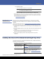
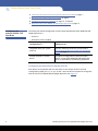
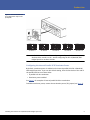
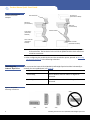
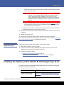
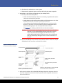
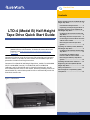
Product Line
Contents
Before Installing the LTO-4 (Model B) HalfHeight Tape Drive ...................................2
Preinstallation Requirements .............2
Unpacking and Inspecting the Drive..3
LTO-4 (Model B) Half-Height
Tape Drive Quick Start Guide
Installing the Internal LTO-4 (Model B)
Half-Height Tape Drive............................3
Configuring the Internal Parallel SCSI
Tape Drive ...........................................4
Mounting the Internal Tape Drive ......6
Connecting the Internal Drive Interface
and DC Power Cables .........................7
Restarting the Internal Tape Drive
System ................................................9
Note: The LTO-4 (Model B) tape drive can ONLY be used with the LTO-4
(Model B) drivers and firmware. To obtain the correct driver and
firmware, visit http://www.quantum.com/ServiceandSupport/
Index.aspx.
Quantum LTO Ultrium tape drives leverage LTO technology and Quantumexclusive features to provide the most reliable and affordable tape data
protection to medium and large businesses.
Quantum LTO-4 (Model B) Half-Height Tape Drives, models TC-L42AX-BR-B
and TC-L42AN-BR-B (internal), TC-L42BX-EY-B and TC-L42BN-EY-B
(tabletop), and TC-L43CX-EY-B and TC-43CN-EY-B (rackmount), are the
most reliable Ultrium drives on the market, delivering reliability features to
extend media life, and Variable-speed Transfer to automatically match the
host's data transfer rate.
Installing the Tabletop LTO-4 (Model B)
Half-Height Tape Drive............................9
Configuring the Tabletop Parallel SCSI
Tape Drive .........................................10
Connecting the Tabletop Drive
Interface and AC Power Cables ........11
Restarting the Tabletop Tape Drive
System ..............................................14
Installing the LTO Driver Software .......14
Registering the LTO-4 (Model B) HalfHeight Tape Drive .................................15
Safety Compliances ..............................15
Electromagnetic Compatibility (EMC)
Compliances .........................................16
Figure 1 Internal Drive
www.quantum.com
Product Name Quick Start Guide
Before Installing the LTO-4 (Model B) Half-Height Tape Drive
Handling Precautions
and Installation
Guidelines
Always observe the following precautions and guidelines when handling and installing
LTO-4 (Model B) Half-Height Tape Drives:
• Internal, at all times
• Tabletop, when removed from its free-standing enclosure
Handling Precautions
• Internal drives have exposed components that are
sensitive to static electricity. To reduce the possibility of
damage from static discharge, the drives are packaged
in a protective antistatic bag. Do not remove the drive
from the antistatic bag until you are ready to install it.
• Wear an ESD-preventive grounding wrist strap or
observe similar ESD precautions when working with the
drive. Be sure the wrist strap makes good skin contact.
Do not remove the wrist strap until you finish working
with the drive.
Also, avoid contact between the drive, other equipment,
and clothing. The wrist strap only protects the
equipment from ESD voltages on the body; ESD
voltages on clothing can still cause damage.
• Before removing the drive from the antistatic bag, touch
a grounded metal surface to discharge any static
electricity buildup from your body.
• Handle the drive by its sides rather than by the top cover
to reduce the risk of dropping the drive or damaging it
during installation.
• Either lay the drive on a nonconductive surface or put it
back inside the protective antistatic bag to reduce the
chance of damage from static discharge
Installation Guidelines
Preinstallation
Requirements
• Due to the high speed of the LTO-4 (Model B) HalfHeight Tape Drive, do not connect more than one LTO-4
(Model B) drive to the same host bus adapter (HBA).
Before installing the LTO-4 (Model B) Half-Height Tape Drive, make sure you have:
• A host bus adapter (HBA) installed and properly configured in the host computer:
• Parallel SCSI HBA for a parallel SCSI drive
• Serial SCSI HBA for a SAS drive
• Interface components:
• For a parallel SCSI drive, either internal or tabletop, a 68-pin parallel SCSI cable
and terminator
2
Before Installing the LTO-4 (Model B) Half-Height Tape Drive
Product Line
• For a SAS drive, either:
• 29-pin SFF-8482 SAS cable for an internal drive
Note: Power is not integrated with the SAS connector. Power is provided
via a separate 4-pin Molex® connector.
• 26-pin SFF-8088 mini-SAS style interface cable for a tabletop drive
• Backup application software that supports the tape drive. For a list of the backup
software applications that have been tested with the LTO-4 (Model B) Half-Height
Tape Drive, please visit our website at:
www.quantum.com/support
Unpacking and
Inspecting the Drive
Although each LTO-4 (Model B) Half-Height Tape Drive is inspected and carefully
packaged at the factory, damage can occur in shipment or when the drive is being
unpacked.
Observe the handling precautions in Handling Precautions and Installation Guidelines,
and carefully unpack and inspect the LTO-4 (Model B) Half-Height Tape Drive as follows:
1 Visually inspect the shipping container and notify your carrier immediately of any
damage.
2 Place the shipping container on a flat, clean, stable surface and carefully remove the
contents.
3 Visually inspect the LTO-4 (Model B) Half-Height Tape Drive and notify your
Quantum representative immediately of any damage.
4 Always save the shipping container and packing materials for any future
reshipment.
Installing the Internal LTO-4 (Model B) Half-Height Tape Drive
To install the internal LTO-4 (Model B) Half-Height Tape Drive, complete the following
procedures in the order presented:
1 Depending on the interface configuration of the drive:
IF the drive interface is . . .
THEN . . .
parallel Small Computer
System Interface (SCSI),
proceed to Configuring the Internal Parallel SCSI
Tape Drive in the following subsection to configure
the parallel SCSI ID and bus terminator power.
serial-attached SCSI (SAS),
there is no need to configure the SCSI ID or bus
termination, as SAS is a point-to-point
architecture. Skip to Mounting the Internal Tape
Drive on page 6
Installing the Internal LTO-4 (Model B) Half-Height Tape Drive
3
Product Name Quick Start Guide
2 Connecting the Internal Drive Interface and DC Power Cables on page 7
3 Restarting the Internal Tape Drive System on page 9
4 Installing the LTO Driver Software on page 14, if required
5 Registering the LTO-4 (Model B) Half-Height Tape Drive on page 15
Configuring the
Internal Parallel SCSI
Tape Drive
The factory-set default configuration of the internal parallel SCSI LTO-4 (Model B) HalfHeight Tape Drive is:
• SCSI ID: 6
• Terminator power: enabled
IF the default parallel SCSI ID
configuration is . . .
THEN you can . . .
compatible with your system
SCSI bus,
skip the following subsection and proceed to
Configuring the Internal Parallel SCSI Terminator
Power on page 5.
already assigned to another
device,
change the configuration of either the other
device, or the LTO-4 (Model B) Half-Height Tape
Drive, as described in the following subsection.
Configuring the Internal Drive Parallel SCSI ID
Each device on the parallel SCSI bus must have its own unique SCSI ID. Use SCSI
configuration jumper pins 1–2, 3–4, 5–6, and 7–8 on the drive back panel to change the
SCSI ID of the LTO-4 (Model B) Half-Height Tape Drive (see figure 2).
4
Installing the Internal LTO-4 (Model B) Half-Height Tape Drive
Product Line
Figure 2 Internal Parallel SCSI
ID Configuration Jumper Pins
(Examples)
TP NC 8 4 2 1
TP NC 8 4 2 1
TP NC 8 4 2 1
SCSI ID 2
SCSI ID 3
SCSI ID 5
TP NC 8 4 2 1
SCSI ID 9
TP NC 8 4 2 1
SCSI ID 13
Note: Parallel SCSI controllers and host adapters generally use ID 7. In some systems,
the boot drive uses ID 0 or ID 1. Avoid configuring the LTO-4 (Model B) HalfHeight Tape Drive to these SCSI IDs.
Configuring the Internal Parallel SCSI Terminator Power
By default, terminator power is enabled on the internal parallel SCSI LTO-4 (Model B)
Half-Height Tape Drive. If you use this default setting, then the last device at the end of
the parallel SCSI bus must have either:
• A parallel SCSI bus terminator
• Terminator power enabled
See figure 3 for examples of internal parallel SCSI bus termination.
To disable terminator power, remove the termination power (TP) jumper (see figure 2).
Installing the Internal LTO-4 (Model B) Half-Height Tape Drive
5
Product Name Quick Start Guide
Figure 3 Internal Parallel
SCSI Bus Termination
Examples
SCSI device
(termination enabled)
SCSI terminator
Tape drive
(no termination)
Tape drive
(no termination)
SCSI terminator
SCSI device
(termination
disabled)
SCSI controller
(termination
enabled)
SCSI controller
(termination enabled)
Note: The internal parallel SCSI LTO-4 (Model B) Half-Height Tape Drive does not provide
SCSI termination. The last device at the end of the parallel SCSI bus chain must have
a SCSI bus terminator.
6 After configuring the parallel SCSI ID and bus termination power, proceed to Mounting
the Internal Tape Drive in the following subsection.
Mounting the
Internal Tape Drive
You can mount the internal LTO-4 (Model B) Half-Height Tape Drive either horizontally or
vertically, but not upside down (see figure 4).
IF you mount the drive . . .
THEN the . . .
horizontally,
base of the drive must be within 15 degrees of
horizontal.
vertically,
side of the drive must be within 5 degrees of
horizontal.
Figure 4 Acceptable
Mounting Orientations
YES
6
YES
YES
NO
Installing the Internal LTO-4 (Model B) Half-Height Tape Drive
Product Line
Mount the internal drive in a 5.25-inch, half-height drive bay as follows:
1 As required:
a Save and close your open files and terminate all running applications.
b Shut down the workstation or server system.
c Disconnect the system AC power cord from the facility AC power receptacle.
2 Remove the cover from the workstation or server system.
Note: See your computer manufacturer’s instructions for the proper procedures to
remove the cover.
3 Select an available 5.25-inch half-height bay and, if required, remove the bay cover.
4 Position the drive in the bay and align either the upper or lower mounting holes—
whichever is appropriate—with the holes in the chassis (see figure 5).
5 Secure the drive using two M3.0 X 3 metric screws on each side
Caution: Using screws longer than 3 mm can damage the drive.
Do not use screws longer than 3 mm to secure the internal LTO-4 (Model B)
Half-Height Tape Drive.
After mounting the internal LTO-4 (Model B) Half-Height Tape Drive, proceed to
Connecting the Internal Drive Interface and DC Power Cables in the following
subsection.
Figure 5 Internal Tape Drive
Mounting Hole Locations
Upper mounting holes
Lower mounting holes
Connecting the Internal
Drive Interface and DC
Power Cables
As shown in figure 6, the rear panel of the internal LTO-4 (Model B) Half-Height Tape
Drive has connectors for:
• Either a 68-pin parallel SCSI or a 29-pin SFF-8482 serial-attached SCSI (SAS) interface
cable
• A serial library interface cable
Installing the Internal LTO-4 (Model B) Half-Height Tape Drive
7
Product Name Quick Start Guide
• The internal drive DC power cable
Figure 6 Internal SCSI Drive
Interface and DC Power
Connectors
68-pin SCSI cable
Figure 7 Internal SAS Drive
Interface and DC Power
Connectors
DC power connector
29-pin SFF-8482 SAS connector
DC power connector
Connect the interface and DC power cables to the internal drive as follows:
1 Verify that the system is shut down and the AC power cord is disconnected from the
facility AC power receptacle.
2 Depending on the interface configuration of your internal drive:
a For the parallel SCSI internal drive:
8
Installing the Internal LTO-4 (Model B) Half-Height Tape Drive
Product Line
• Attach the internal SCSI interface cable to the 68-pin parallel SCSI connector
on the back of the drive.
Caution: The LTO-4 (Model B) Half-Height Tape Drive with the parallel SCSI
interface is a low voltage differential (LVD) SCSI device. Install it
only in LVD environments. Plugging an LVD drive into a high
voltage differential (HVD) bus makes the entire bus nonfunctional
and may permanently damage the drive or other SCSI devices on
the bus.
• See the internal parallel SCSI bus termination examples in figure 3 on page 6
to check/verify the system SCSI bus configuration and install a 68-pin LVD
SCSI bus terminator, as required.
b For the SAS internal drive, attach the internal SAS interface cable to the 29-pin
SFF-8482 SAS connector on the back of the drive.
3 Connect the internal drive DC power cable to the DC power connector on the back
of the drive.
4 Reinstall the system cover.
5 Reconnect the system AC power cord to the facility AC power receptacle.
After connecting the internal drive interface and DC power cables, proceed to Restarting
the Internal Tape Drive System in the following subsection.
Restarting the Internal
Tape Drive System
After connecting the internal drive interface and DC power cables:
1 Restart the workstation or server system.
2 Verify that the internal LTO-4 (Model B) Half-Height Tape Drive comes on and
completes the Power On Self Test (POST) functions.
3 As required, proceed to either:
• Installing the LTO Driver Software on page 14
• Registering the LTO-4 (Model B) Half-Height Tape Drive on page 15
Installing the Tabletop LTO-4 (Model B) Half-Height Tape Drive
To install the tabletop LTO-4 (Model B) Half-Height Tape Drive, complete the following
procedures in the order presented:
1 Depending on the interface configuration of the drive:
IF the drive interface is . . .
THEN . . .
parallel Small Computer
System Interface (SCSI),
proceed to Configuring the Tabletop Parallel SCSI
Tape Drive in the following subsection to configure
the SCSI ID.
Installing the Tabletop LTO-4 (Model B) Half-Height Tape Drive
9
Product Name Quick Start Guide
IF the drive interface is . . .
THEN . . .
serial-attached SCSI (SAS),
there is no need to configure the SCSI ID, as SAS is
a point-to-point architecture. Skip to Connecting
the Tabletop Drive Interface and AC Power Cables
on page 11.
1 Configuring the Tabletop Parallel SCSI Tape Drive
2 Connecting the Tabletop Drive Interface and AC Power Cables on page 11
3 Restarting the Tabletop Tape Drive System on page 14
4 Installing the LTO Driver Software on page 14, if required
5 Registering the LTO-4 (Model B) Half-Height Tape Drive on page 15
Configuring the
Tabletop Parallel SCSI
Tape Drive
The factory-set default configuration of the tabletop parallel SCSI LTO-4 (Model B) HalfHeight Tape Drive is:
• SCSI ID: 6
• Terminator power: enabled
IF the default parallel SCSI ID
configuration is . . .
THEN you can . . .
compatible with your system
SCSI bus,
skip the following subsection and proceed to
Configuring the Internal Parallel SCSI Terminator
Power on page 5.
already assigned to another
device,
change the configuration of either the other
device, or the LTO-4 (Model B) Half-Height Tape
Drive, as described in the following subsection.
Note: You cannot disable terminator power on a tabletop parallel SCSI drive.
Configuring the Tabletop Drive Parallel SCSI ID
Each device on the parallel SCSI bus must have its own unique SCSI ID. Use the pushbutton SCSI ID selector switch on the drive back panel to change the SCSI ID of the
tabletop LTO-4 (Model B) Half-Height Tape Drive (see figure 8).
10
Installing the Tabletop LTO-4 (Model B) Half-Height Tape Drive
Product Line
Figure 8 Tabletop Parallel SCSI
ID Selector Switch
Parallel SCSI ID selector switch
Note: Parallel SCSI controllers and host adapters generally use ID 7. In some systems,
the boot drive uses ID 0 or ID 1. Avoid configuring the LTO-4 (Model B) HalfHeight Tape Drive to these SCSI IDs.
6 After configuring the parallel SCSI ID, proceed to Connecting the Tabletop Drive
Interface and AC Power Cables in the following subsection.
Connecting the
Tabletop Drive Interface
and AC Power Cables
As shown in figure 9 and figure 10, the rear panels of the tabletop LTO-4 (Model B) HalfHeight Tape Drives have connectors for:
• Either a 68-pin parallel SCSI cable (two connectors), or a 26-pin SFF-8088 mini-SAS
style interface cable
• The AC power cable
For the tabletop parallel SCSI drive, either SCSI connector can be used as a SCSI IN or
SCSI OUT connection. This means you can use either connector to attach the drive to a
host computer or to another parallel SCSI device.
Installing the Tabletop LTO-4 (Model B) Half-Height Tape Drive
11
Product Name Quick Start Guide
Figure 9 Tabletop SCSI Drive
Interface and AC Power
Connectors
68-pin parallel SCSI connectors
AC power switch
AC power connector
Figure 10 Tabletop SAS Drive
Interface and AC Power
Connectors
26-pin SFF-8088 mini-SAS connector
AC power switch
AC power connector
Connect the interface and AC power cables to the tabletop drive as follows:
1 As required:
a Save and close your open files and terminate all running applications.
12
Installing the Tabletop LTO-4 (Model B) Half-Height Tape Drive
Product Line
b Shut down the workstation or server system.
c Disconnect the system AC power cord from the facility AC power receptacle.
2 Depending on the interface configuration of your tabletop drive:
a For the parallel SCSI tabletop drive:
• Attach the SCSI IN interface cable to one of the 68-pin parallel SCSI interface
connectors on the back of the drive.
• Attach either the SCSI OUT interface cable or a SCSI terminator to the other
parallel SCSI interface connector on the back of the drive.
If the tabletop LTO-4 (Model B) Half-Height Tape Drive is the last or only
device in a SCSI chain, you must install a 68-pin low voltage differential
(LVD) terminating plug on the unused parallel SCSI connector.
See figure 11 for tabletop parallel SCSI bus termination examples.
Caution: The LTO-4 (Model B) Half-Height Tape Drive with the parallel SCSI
interface is a low voltage differential (LVD) SCSI device. Install it
only in LVD environments. Plugging an LVD drive into a high
voltage differential (HVD) bus makes the entire bus nonfunctional
and may permanently damage the drive or other SCSI devices on
the bus.
b For the SAS tabletop drive, attach the external SAS interface cable to the 26-pin
SFF-8088 mini-SAS connector on the back of the drive.
Figure 11 Tabletop Parallel
SCSI Bus Termination Examples
SCSI terminators
External tape drive
External SCSI
device
SCSI controller
(termination
enabled)
Example 1: SCSI termination in a system
that has only external SCSI devices.
External SCSI device
External tape drive
SCSI controller (termination
disabled)
Internal SCSI device (termination
enabled
Example 2: SCSI termination in a system that has
both internal and external SCSI devices.
3 Verify that the tabletop LTO-4 (Model B) Half-Height Tape Drive AC power switch is
set to the off position, and connect the AC power cord to the power connector on
the back of the drive.
Installing the Tabletop LTO-4 (Model B) Half-Height Tape Drive
13
Product Name Quick Start Guide
4 Connect the drive AC power cord to the facility AC power receptacle.
5 Reconnect the workstation or server system AC power cord to the facility AC power
receptacle.
After connecting the tabletop drive interface and AC power cables, proceed to
Restarting the Tabletop Tape Drive System in the following subsection.
Restarting the Tabletop
Tape Drive System
After connecting the tabletop drive interface and AC power cables:
1 Set the tabletop drive AC power switch to the on position.
2 Restart the workstation or server system.
3 Verify that the tabletop LTO-4 (Model B) Half-Height Tape Drive comes on and
completes the Power On Self Test (POST) functions.
As required, proceed to either:
• Installing the LTO Driver Software
• Registering the LTO-4 (Model B) Half-Height Tape Drive
Installing the LTO Driver Software
Note: The LTO-4 (Model B) tape drive can ONLY be used with the LTO-4 (Model B)
drivers and firmware. To obtain the correct driver and firmware, visit http://
www.quantum.com/ServiceandSupport/Index.aspx.
If you intend to use the LTO-4 (Model B) Half-Height Tape Drive with the Microsoft®
native backup applet on a Windows 2000, Windows Server® 2003, Windows XP®, or
Windows Vista operating system, install the appropriate version of the LTO driver
software. (See the Downloads page for LTO-4 (Model B) drivers under Standalone Tape
Drives on the Quantum support website at: www.quantum.com/support.)
Note: The LTO driver software is not necessary with commercial backup application
software.
14
Installing the LTO Driver Software
Product Line
Registering the LTO-4 (Model B) Half-Height Tape Drive
After installing the LTO-4 (Model B) Half-Height Tape Drive, be sure to register it via the
Quantum website at:
www.quantum.com/registration
Registering the drive ensures that you will receive the latest technical information about
the drive, as well as other product, service, and support information.
Safety Compliances
The LTO-4 (Model B) Half-Height Tape Drives are safety compliant with the following
regulatory organizations and codes in the countries indicated:
Country
Regulatory Organization
Compliant to:
Canada
Canadian Standards Association
(CSA)
UL/CSA 60950-1
EU member nations
Comité Europèen de Normalisation
Electrotechnique – the European
Committee for Electrotechnical
Standardization (CENELEC)
EN 60950-1, 1st
edition
IECEE member
nations*
IECEE International Electrotechnical
Commission on Electrical
Equipment (IECEE) for Mutual
Recognition of Test Certificates for
Electrical Equipment “CB Scheme”
CB Scheme per IEC
60950-1 with details
and exceptions for
each member country
Israel
SII
CB Scheme
Taiwan
BSMI
BSMI certification, CNS
14336
United States
Underwriters Laboratories (UL)
UL/CSA 60950-1
* IECEE member nations include: Argentina, Austria, Australia, Belgium, Brazil,
Canada, China (PR), Czech Republic, Denmark, Finland, France, Germany, Hungary,
India, Ireland, Israel, Italy, Japan, (South) Korea, Montenegro, Netherlands, Norway,
Poland, Russian Federation, Serbia, Singapore, Slovakia, Slovenia, South Africa, Spain,
Switzerland, Turkey, United Kingdom, and USA.
Registering the LTO-4 (Model B) Half-Height Tape Drive
15
Product Name Quick Start Guide
Electromagnetic Compatibility (EMC) Compliances
The LTO-4 (Model B) Half-Height Tape Drives are EMC compliant with the following
regulatory organizations and codes in the countries indicated:
Country
Regulatory Organization
Compliant to:
Australia
Australian Communications and
Media Authority (ACMA)
AS/NZS 3548 (same as
CISPR 22)
Canada
Industry Canada Digital Apparatus Interference-Causing Equipment
Standard
(ICES-003)
ICES-003 Digital
Apparatus
EU member nations
CE
Emissions per CISPR
22, EN55022 and
Immunity per CISPR
24, EN55024
Israel
SII
CISPR 22 and CISPR 24
Japan
Voluntary Control Council for
Interface (VCCI)
VCCI
New Zealand
Australian Communications and
Media Authority (ACMA)
AS/NZS 3548 (same as
CISPR 22)
South Korea
MIC
CISPR 22 and CISPR 24
Taiwan
Bureau of Commodity Inspection
and Quarantine (BSMI)
BSMI EMC
certification, CNS
14338
United States
Federal Communications
Commission (FCC)
Title 47: Code of
Federal Regulations,
Part 15, Subpart B
(47CFR15B),
Note: Use these drives only in equipment where the combination has been
determined to be suitable by an appropriate certification organization (for
example, Underwriters Laboratories Inc. or the Canadian Standards Association
in North America).
You should also consider the following safety points:
• Install the drive in an enclosure that limits the user’s access to live parts, gives
adequate system stability, and provides the necessary grounding for the drive.
• Provide the correct voltages (+5 VDC and +12 VDC) based on the regulation
applied—Extra Low Voltage (SEC) for UL and CSA, and Safety Extra Low Voltage for
BSI and VDE (if applicable).
16
Electromagnetic Compatibility (EMC) Compliances
Product Line
Electromagnetic Compatibility (EMC) Compliances
17
Product Name Quick Start Guide
*6-66847-01*
18
6-66847-01 Rev A, January 2010
For assistance, contact the Quantum Customer Support Center:
USA:
800-284-5101 (toll free) or 949-725-2100
EMEA: 00800-4-782-6886 (toll free) or +49 6131 3241 1164
APAC:
+800 7826 8887 (toll free) or +603 7953 3010
Worldwide: http://www.quantum.com/ServiceandSupport
Backup. Recovery. Archive. It’s What We Do.
©2010 Quantum Corporation. All rights reserved. Quantum, the Quantum logo, and all
other logos are registered trademarks of Quantum Corporation or of their respective owners.
Protected by Pending and Issued U.S. and Foreign Patents, including U.S. Patent No. 5,990,810.
About Quantum
Quantum Corp. (NYSE:QTM) is the leading global storage company
specializing in backup, recovery and archive. Combining focused
expertise, customer-driven innovation, and platform independence,
Quantum provides a comprehensive range of disk, tape, media and
software solutions supported by a world-class sales and service
organization. This includes the DXi™-Series, the first disk backup
solutions to extend the power of data deduplication and replication
across the distributed enterprise. As a long-standing and trusted
partner, the company works closely with a broad network of
resellers, OEMs and other suppliers to meet customers’ evolving
data protection needs.