1
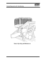
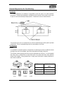
Owner’s Manual Using the Ducted Evaporative Air Conditioning with Your Manual Control Operating, Installation & Maintenance Please keep this important manual in a safe place. It is the owner’s responsibility to ensure that regular maintenance is carried out on this Ducted Evaporative Air Conditioner. Failure to do so will void all guarantees beyond statutory and legal requirements. www.climatetechnologies.com.au PNE2002 Series Control Manual Comfort Control Notes Introduction Congratulations on your choice We are delighted you have chosen an air conditioning product from Climate Technologies to cool your home. It’s an air conditioner we’re very proud of. Designed and made in Australia by Climate Technologies, a 100% Australian owned company, it contains the latest advances in Fresh Air Conditioning technology in a stylish, attractive cabinet. Climate Technologies is constantly researching and developing improved product features and therefore reserves the right to change specifications without notice. E.&O.E. PNE2002 Series Control Page 2 Manual Comfort Control Notes INTRODUCTION ................................................................................................2 CONGRATULATIONS ON YOUR CHOICE ......................................................................... 2 DUCTED EVAPORATIVE AIR CONDITIONING ...............................................5 INTRODUCTION .......................................................................................................... 6 UNIT OPERATION ....................................................................................................... 6 Exhaust...............................................................................................................................................6 Bleed-off .............................................................................................................................................7 OPERATING THE CONTROLS .........................................................................8 CONTROL FUNCTIONS ................................................................................................ 8 Using the Fan Mode............................................................................................................................8 Using the Cool Mode ..........................................................................................................................8 Pre-Cool..............................................................................................................................................8 CONTROL INSTALLATION & SETUP ..............................................................9 INSTALLING THE CONTROL ......................................................................................... 9 Before Starting....................................................................................................................................9 Installation...........................................................................................................................................9 SETTING UP THE CONTROL ...................................................................................... 10 Setting Minimum Fan Speed.............................................................................................................10 Setting Maximum Fan Speed............................................................................................................10 Setting up the Dump Valve (Where Fitted) .......................................................................................10 PROBLEM SOLVING .................................................................................................. 11 COMMISSIONING CHECK LIST.................................................................................... 12 General .............................................................................................................................................12 Unit - Ducted Evaporative Air Conditioner ........................................................................................12 Ductwork...........................................................................................................................................13 Site....................................................................................................................................................13 Customer Hand Over ........................................................................................................................13 DUCTED EVAPORATIVE AIR CONDITIONER MAINTENANCE ...................14 GENERAL ................................................................................................................ 14 FILTER PADS ........................................................................................................... 14 WATER TANK ........................................................................................................... 14 WATER LEVEL / FLOAT VALVE................................................................................... 15 MOTOR AND FAN ...................................................................................................... 15 ELECTRICAL............................................................................................................. 15 BLEED OFF .............................................................................................................. 15 PUMP ...................................................................................................................... 15 WATER DISTRIBUTION .............................................................................................. 15 WARRANTY.....................................................................................................16 WARRANTY STATEMENT. .......................................................................................... 16 Conditions And Exclusions ...............................................................................................................16 WARRANTY ON REPLACEMENTS PARTS. ................................................................... 17 PERIOD OF W ARRANTY – YEARS .............................................................................. 17 PROOF OF PURCHASE ............................................................................................. 18 DEALER / PRODUCT INFORMATION ............................................................................ 18 SERVICE..........................................................................................................19 PNE2002 Series Control Page 3 Manual Comfort Control Notes PNE2002 Series Control Page 4 Manual Comfort Control Ducted Evaporative Air Conditioning Ducted Evaporative Air Conditioning Owners Operating and Maintenance PNE2002 Series Control Page 5 Manual Comfort Control Ducted Evaporative Air Conditioning Introduction Your ducted evaporative air conditioner is engineered to meet the rigors of our harsh Australian environment. Operated and maintained in accordance with this manual, it will provide you with years of quiet, cool and environmentally friendly operation. Please take the time to read this manual. The principal of your unit is to introduce fresh air, which is washed through the filter pads to provided cool fresh air. The air is exhausted taking with it any heat loading on the home. Unit Operation Exhaust It is essential for successful operation of evaporative air-conditioning that there be sufficient exhaust openings in the area to be ventilated. Open doors and windows will usually provide this. The minimum exhaust opening should be as per the table guide set out below. It is recommended that ceiling vents or exhaust fans be used where there is any doubt about there being sufficient exhaust area available. Ceiling exhaust fans or ceiling vents should have a capacity equivalent to that of the air conditioner. MODEL MINIMUM EXHAUST AREA Small Medium Large PNE2002 Series Control 0.85 m² 1.19 m² to 1.48 m² 2.02 m² Page 6 Manual Comfort Control Ducted Evaporative Air Conditioning Bleed-off All evaporative air conditioners need some water bleed-off to prevent build-up of mineral deposits in the system. The correct setting of the bleed rate will ultimately govern the life of the unit. With normal town water supply, bleed rate should be adjusted so that the discharge is not less than approximately 10 litres per hour. Increased water hardness may require a higher bleed rate and increased maintenance. The method for setting the bleed rate is to adjust the patented DIALFLO unit located externally on the unit. It is recommended to plumb the bleed-off away from the unit to a down pipe in situations where the discharge may cause unsightly stains, e.g. Colorbond Roofs. If dump valve fitted and dumping cycles activated, bleed off may not be required. Note: To control water volume to filter pad rotate filter anti-clockwise for more water and clockwise for less water. To control bleed-off rate rotate bleed dial clockwise for more water and anti-clockwise for less water. PNE2002 Series Control Page 7 Manual Comfort Control Operating the Controls Operating the Controls Control Functions The MANUAL control is a simple low voltage controller that allows you to operate each function of the product as required to keep you home cool. As there is no thermostat in the Manual control it can be located anywhere that is convenient to the customer and the installer. To use the control you will need to turn the fan ON, or the fan and cool switches ON to operate . Using the Fan Mode Using the fan mode on the Manual control the unit will operate the fan only providing ventilation in the building. 1. To activate the room air fan, turn the Fan ON / OFF switch on by toggling the switch to the right. 2. To adjust the speed of the fan, rotate the Fan Speed control knob. Clockwise will increase the air and anti-clockwise will decrease the air. Your product is fitted with a variable speed fan motor and therefore can be adjusted to your desired level of air. 3. To turn the fan OFF toggle the Fan ON / OFF switch to the left. The fan will now stop. Using the Cool Mode Using the cool mode introduces the pump. When the pump is turned ON water will be pumped around the water distribution system saturating the filter pads. 1. To activate the pump, turn the Cool ON/OFF switch on by toggling the switch to the right. The pump will now pump water around the water distributor saturating the filter pads. 2. To turn the pump OFF, toggle the Cool switch to the left and the pump will stop. Pre-Cool As the Manual control does not have a pre-cool function, this can be simulated by: 1. Turn ON the Cool switch first and allow the pump to operate for 3 to 5 minutes. This will allow the filter pads to be saturated with water before the fan starts. 2. After the 3 to 5 minutes is complete, turn ON the Fan switch. The unit will deliver cool fresh air with in seconds of the fan starting. If you do not wish to wait for the pre-cool period, the fan can be turned on at the same time as the pump and the air will eventually become cool as the filters saturate. NOTE: Normally during the first 10 days of operation a slight odor will be present from the CELDEK filter pads. This 'new smell' is quite normal, and will quickly disappear as your unit is operated. PNE2002 Series Control Page 8 Manual Comfort Control Control Installation & Setup Control Installation & Setup Installing The Control Before Starting Before attempting to locate the control, check that the 20 metre cable supplied will reach between the air conditioner and the proposed wall control position. For the unit to function a jumper supplied with the wall control must be fitted to the air conditioner control box. NOTE: Do not run the low voltage loom in long parallel runs with 240V mains cables. Keep the low voltage loom 200mm away from any long runs of mains wiring. Cross over mains wiring at right angles. Do not use existing access holes in wall cavities where 240V mains wiring exists. Drill a new access hole 200mm from the existing hole. Installation As the MANUAL control has no thermostat, the control can be installed anywhere that is suitable to the customer and installer. • Fit the communication cable through the dropper duct when installing the unit on the roof. • Connect cable to one of the communication ports in the control box. • Drill an access hole through wall where the control will be positioned. • Pull the low voltage cable down the wall and through the access hole. • Fit the MANUAL wall control base plate to the wall. • Connect the communication cable to either port in the control box. • Connect the communication cable to the port in the wall control. • Fit the wall control to the base. • Fit the black jumper provided to pins 1 & 2 in the air conditioner control box. See wiring diagram . • Connect the 240V power to the unit. • Turn the unit isolating switch on. The unit is now ready for operation. NOTE: Check the jumper has been fitted to pins 1 & 2 on the unit control board. If a service call results in a jumper not being fitted, the customer will receive a charge for the service call out. PNE2002 Series Control Page 9 Manual Comfort Control Control Installation & Setup Setting Up The Control The MANUAL control does not come with any maintenance functions to set the high or low fan speeds. To set the high or low fan speeds an RF/LV digital control is required to set and save the settings in the unit control. Setting Minimum Fan Speed 1. Using the MANUAL/AUTO button set the unit to MANUAL 2. Using the HEAT/COOL/FRESH AIR button set the unit to COOL FRESH AIR 3. Adjust the fan speed to the minimum fan speed level and press ENTER. 4. Press the ENTER and ECONOMY/ BOOST buttons together for approximately 10 seconds pressing the ENTER button first. 5. The words FAN SPEED and a number under the room temperature will flash. 6. Adjust minimum fan speed to a number suitable to the system design. Ensure that the motor does not over-temp if setting the fan speed lower. 7. Press ENTER to keep new fan speed. Setting Maximum Fan Speed Maximum fan speed can only be access after the minimum fan speed has been checked. 1. Using the MANUAL/AUTO button ensure MANUAL is still selected. 2. Using the ECONOMY/BOOST button set the unit to BOOST. Press ENTER. 3. Press the ENTER and ECONOMY/ BOOST buttons together for approximately 10 seconds pressing the ENTER button first. 4. The words FAN SPEED and a number under the room temperature will flash. 5. Adjust maximum fan speed to 35 or a number to suit the system design. 6. Press ENTER to keep new fan speed. Setting up the Dump Valve (Where Fitted) A dump valve can be fitted to a unit using the MANUAL control. There are no timer control functions available with this control. The dump valve solenoid is activated or deactivated when the pump operation is used. PNE2002 Series Control Page 10 Manual Comfort Control Control Installation & Setup Problem Solving PROBLEM Unit fails to start Pump fails to start Water leaking from overflow Water Droplets in air stream Excessive humidity Inadequate Cooling Unpleasant Odor Rapid formation of white deposits on pads PROBABLE CAUSE REMEDY a Black – out a Wait b Tripped Circuit Breaker b Reset c Blown Fuse c Replace d Electrical Fault d Call Climate Technologies Service Provider a Pump Seized a Isolate power and then take off top of pump and try to free it. Some lubricant may help. b Pump Burnt Out b Call Climate Technologies Service Provider a Float Valve Leaking a Check adjustment or replace seal b Drain from Celdek Pads b Normal Operation a Loose Delivery Tube a Check and tighten b Break in tubing b Replace as necessary c Pump Delivers Excessive Water to Pads c Adjust the Dialflo to reduce the flow a Inadequate Exhaust a Provide more open area to exhaust stale air b Outside humidity high b Turn pump off. a Dirty Filters a Clean b Dry Filters b Check water delivery system. Adjust if necessary. c Dialflo not set correctly c Adjust Dialflo so that the pads have even saturation. a Unit located near odor source a Remove source b New Celdek filter smell b Smell will disappear after a period of operation. High Mineral Content Bleed off should be set at maximum. More regular maintenance may be required. THIS TROUBLE SHOOTING GUIDE IS A REFERENCE ONLY. FOR SERVICE OR WARRANTY REQUIREMENTS PLEASE REFER TO THE END OF THESE INSTRUCTIONS PNE2002 Series Control Page 11 Manual Comfort Control Control Installation & Setup Commissioning Check List General All equipment ordered by the customer is installed. The unit is level and secure. The mains and control wiring are complete and the circuit breaker and GPO are turned ON. All Controller functions for the appliance operate. All electrical or water connections are to manufacturers specifications and the relevant electrical or plumbing standards and codes. Unit - Ducted Evaporative Air Conditioner The water supply line has been flushed to clear swarf and debris and is free of leaks. The tank is free of foreign matter and debris and the water isolating tap is turned ON. Water drainpipe work is completed and sealed. The water basin fills with water and the float valve closes correctly when the water level is 6570mm below the overflow level. The water pump operates correctly when turned ON at the controller. The Dialflo water bleed rate is adjusted to suit local water conditions. The Superclean Dump Valve (option). The tank drains correctly when unit turns off. The fan deck is correctly located and the fan blade spins freely. The fan operates through the entire speed range. The minimum fan speed is correctly set. Water distribution is even with the filter pads fitted and the air conditioner operating pump and fan. Areas of high water pressure (Exceeding 500Kpa) a water pressure limiting valve must be fitted in accordance with AS3500. Consequential damage from high water pressure is not covered by warranty. PNE2002 Series Control Page 12 Manual Comfort Control Control Installation & Setup Ductwork All ductwork is completed to plan, correctly supported and airtight, with no bend less than 1.5 x the ductwork diameter. Air distribution checked, dampers are adjusted and all outlets correctly adjusted and wiped clean. All roof penetrations are fully sealed and watertight. Man hole cover replaced. Site All rubbish has been removed from inside and on the roof. Customer Hand Over The operation of the Controller. The need to open windows and doors for the correct operation of Fresh Air Conditioning The operation of the bleed or dumping system and it’s importance to operate all the time in ducted fresh air conditioning Maintenance requirements PNE2002 Series Control Page 13 Manual Comfort Control Unit Mantenance DUCTED EVAPORATIVE AIR CONDITIONER MAINTENANCE General All Ducted Evaporative Air Conditioners benefit from some general maintenance to ensure continued cooling efficiency and a long life. Maintenance is carried out at the beginning and end of summer to start up and close down your unit. We recommend that all maintenance work be undertaken by our fully trained and accredited Service Technicians or an authorized Climate Technologies Service Provider. The frequency of general maintenance will depend on local operating conditions such as water quality, air borne dust and pollen. It is essential that your evaporative air conditioner is maintained in accordance with this manual. Failure to do so will effect the life of the product and reduce the level of efficiency. For service Australia wide refer to the details on the rear of the manual. NOTE: The manufacturer and it's service providers reserve the right to refuse service unless safety and accessibility to the unit can be guaranteed. The cost of any extra equipment required to provide access to the unit for servicing is the responsibility of the owner. SAFETY: Prior to commencing any maintenance isolate the unit at the power source. Ensure the roof is safe to access, your ladder is securely positioned and you're wearing suitable, sturdy non-slip footwear. Filter Pads Visually check CELDEK pads for damage or blockage. Hose down pads from both sides to remove any build up of salts, dust and pollen. In dusty areas more regular cleaning is recommended. Check the water distributor, making sure it is clear and free from blockage. Failure to do so may lead to uneven water distribution and therefore less efficient operation. Water Tank It is important to keep the water tank clean and free from sediment and algae growth. To clean the tank, use a soft brush or similar. Wipe all surfaces in the tank while it is full of water (DO NOT FORGET THE PUMP STRAINER). Turn off the water inlet to the unit (an Isolation Valve should be fitted to the water inlet before the Float Valve). Drain the tank by removing the 40mm standpipe. It may be necessary to repeat this procedure if the tank is very dirty. Safety: Wet roofs are dangerous – Take Care When Draining Tank. PNE2002 Series Control Page 14 Manual Comfort Control Unit Mantenance Water Level / Float Valve The water level should be set at nominal 65-70mm from the top of the overflow before filter pads are saturated. After run off from the operating pump / filters the level from the top of the overflow fitting should be 25 – 30mm. The float valve is a mechanical type and is factory set. If it requires adjustment keep bends tight. If the valve is leaking the seal may require cleaning or replacing. 9 Turn the water off 9 Remove the split pin and then float arm. 9 Remove piston and clean or turn seal. 9 Flush system 9 Replace piston, float arm and split pin. Note: Water supply line to float valve must be flushed before connecting. Note: Some discharge from the overflow may be experienced after shut down due to water draining back from the Celdek pads. This is normal. Motor and Fan Check that the fan spins freely and that there is no build up on the blades. Electrical No general maintenance is required to the electrical system. A Qualified Electrician should only carry out electrical connections and maintenance. Bleed Off The bleed rate should be checked to ensure it is adequate and that there is no build up of mineral deposits in or on your air conditioner. White deposits indicate high mineral content and the Bleed Rate should be increased. If it is at maximum and the deposits are still forming, then more regular maintenance is required. Pump Check the pump spins freely and that the strainer is clean. Water Distribution Check the water distribution system for blockage. Check the delivery tube for kinks or holes. Check that the clamps are secure and in place. PNE2002 Series Control Page 15 Manual Comfort Control Warranty – Australia ONLY Warranty Warranty Statement. Subject to the following conditions we provide, from the dated proof of purchase, the following warranty: Any part found to be defective in workmanship or material within the period of warranty will be replaced free of charge. The structural warranty covers any structural components within the unit, which fail to perform their intended function due to faulty manufacture or deterioration within the warranty period. Conditions And Exclusions • Travelling time and mileage are included within 30km of either your authorized Climate Technologies dealer or service provider’s premises. Customers in areas other than the above are responsible for any travelling time and mileage required to carry out warranty repairs. • The product must have been installed in the manner prescribed by local statutory regulations and to the manufacturer’s specifications by a qualified person. • Service within the terms of this warranty will be recognized where we are satisfied that the appliance or part was supplied within the relevant time limits. Documents of purchase and Dealer/Installer information will assist in this process. • A charge will be made for work or a service call where there is nothing wrong with the appliance or where the defective operation of the appliance is due to failure of electricity or water supply, or where defects are caused by neglect, incorrect application, abuse or by accidental damage of the appliance, or by an unauthorized person attempting to repair the appliance. • No responsibility will be accepted for outside elements such as pests, animals, pets and vermin that may cause damage to the unit. • Harsh environmental situations such as salt air that may cause cabinet or electronic damage can not be considered warranty. • Claims for damage to contents, carpet, walls, ceilings, foundations or any other consequential loss either direct or indirect resulting from, power spikes, incorrect operation, incorrect installation or faulty product are excluded. NOTE: In addition to this warranty, the Trade Practices Act and similar laws in each state provide the owner, under certain circumstances, with minimum statutory rights in relation to the product. This warranty must be read subject to that legislation and nothing in this warranty has the effect of excluding, restricting or modifying those rights. PNE2002 Series Control Page 16 Manual Comfort Control Warranty – Australia ONLY Warranty On Replacements Parts. Parts replace under warranty are warranted for the balance of the original warranty period. Period Of Warranty – Years Unit Components RESIDENTIAL Parts Labour COMMERCIAL Parts Labour Corrosion on Cabinet 25 3 2 2 Structural Guarantee 10 3 2 2 ** All other components 3 3 1 1 ** Filter pads are a consumable item and therefore are not covered by the above warranty periods. PNE2002 Series Control Page 17 Manual Comfort Control Warranty – Australia ONLY Proof Of Purchase It is important that the name of the Dealer or Retailer from whom you purchased your product and the name of the installer is recorded on this page. The installer is responsible for the correct installation, start up and demonstrating the operation of this product. He is also responsible for issuing the relevant certificates of compliance for the electrical and gas connections. (These may differ from state to state) Please attach your proof of purchase here. Your receipt is your warranty and will be required to validate any warranty. Dealer / Product Information Dealer/Retailer: Dealer Address: Dealer Phone Number: Unit Model Number: Serial No: Date Installed: Installed by: PNE2002 Series Control Page 18 Manual Comfort Control Warranty – Australia ONLY SERVICE. A qualified service technician should conduct any service work carried out on your ducted gas central heating or cooling product. It is important that periodical service is carried out on your product to ensure your will receive the efficiency benefits the product provides. An authorized Climate Technologies service provider must carry out warranty service. For Metro Service only ring the numbers below. South Australia (08) 8307 5230 NSW / ACT (02) 6953 5968 Western Australia (08) 9454 1000 Victoria (03) 8795 2456 Outside Metro areas please contact your nearest Climate Technologies Service Provider. PNE2002 Series Control Page 19 Manufactured by: ABN 13 001 418 042 Adelaide Site 26 Nylex Avenue SALISBURY SA 5108 Phone (08) 8307 5100 (08) 8283 0401 Fax PNE2002 Series Leeton Site 9-11 McKay Avenue LEETON NSW 2705 Phone (02) 6953 6444 Fax (02) 6953 6266 6052223/C