1
Luft/WasserWärmepumpe für
Innenaufstellung
Installation and
Operating Instructions
English
Instructions d’installation
et d’utilisation
Français
Montage- und
Gebrauchsanweisung
Air-to-Water
Heat Pump for
Indoor Installation
Bestell-Nr. / Order no. / No de commande : 452160.66.20
Deutsch
LI 20TEL
LI 24TEL
LI 28TEL
Pompe à chaleur
air-eau pour
installation
intérieure
FD 8611
Table of contents
1
Please Read Immediately .............................................................................................................E-2
1.1 Important Information:............................................................................................................................. E-2
1.2 Legal Regulations and Directives ........................................................................................................... E-2
1.3 Energy-Efficient Use of the Heat Pump .................................................................................................. E-2
2
Purpose of the Heat Pump ...........................................................................................................E-3
3
Scope of Delivery ..........................................................................................................................E-3
3.1 Basic Device ........................................................................................................................................... E-3
3.2 Switch Box .............................................................................................................................................. E-4
3.3 Heat Pump Controller ............................................................................................................................. E-4
4
Transport........................................................................................................................................E-4
5
Set-UP.............................................................................................................................................E-5
5.1 General Information ................................................................................................................................ E-5
5.2 Condensed Water Pipe........................................................................................................................... E-5
5.3 Sound ..................................................................................................................................................... E-5
6
Installation .....................................................................................................................................E-5
6.1
6.2
6.3
6.4
7
General Information ................................................................................................................................ E-5
Air Connection ........................................................................................................................................ E-5
Heating System Connection ................................................................................................................... E-6
Electrical Connection .............................................................................................................................. E-6
Start-UP ..........................................................................................................................................E-7
7.1 General Information ................................................................................................................................ E-7
7.2 Preparation ............................................................................................................................................. E-7
7.3 Procedure ............................................................................................................................................... E-7
8
Maintenance / Cleaning ................................................................................................................E-8
8.1 Maintenance ........................................................................................................................................... E-8
8.2 Cleaning the Heating System ................................................................................................................. E-8
8.3 Cleaning the Air System ......................................................................................................................... E-8
9
Faults / Trouble-Shooting .............................................................................................................E-8
10 Decommissioning/Disposal .........................................................................................................E-8
11 Device Information ........................................................................................................................E-9
Anhang / Appendix / Annexes ............................................................................................................ A-I
www.dimplex.de
E-1
English
2.1 Application .............................................................................................................................................. E-3
2.2 Operating Principle ................................................................................................................................. E-3
1
1
Please Read
Immediately
1.1
Important Information:
ATTENTION!
The device is not suitable for operation with a frequency converter.
ATTENTION!
English
When transporting the heat pump, ensure that it is not tilted more than
45° (in any direction).
ATTENTION!
The heat pump and transport pallet are only joined by the packing film.
ATTENTION!
Do not restrict or block the area around the air intake or outlet.
ATTENTION!
Only operate the heat pump with the air ducts connected.
ATTENTION!
Ensure that there is a clockwise rotating field: Operating the compressor
in the wrong rotational direction could cause damage to the compressor.
ATTENTION!
Never use cleaning agents containing sand, soda, acid or chloride as
these can damage the surfaces.
ATTENTION!
We recommend the installation of a suitable corrosion protection system
to prevent the formation of deposits (e.g. rust) in the condenser of the
heat pump.
ATTENTION!
Before opening the device, ensure that all circuits are isolated from the
power supply.
ATTENTION!
Any work on the heat pump may only be performed by authorised and
qualified after-sales service technicians.
E-2
1.2
Legal Regulations and
Directives
The construction and design of the heat pump complies with all
relevant EU directives, DIN/VDE regulations (see CE declaration
of conformity).
When connecting the heat pump to the power supply, the relevant VDE, EN and IEC standards are to be fulfilled. Any further
connection requirements stipulated by local utility companies
must also be observed.
When connecting the heating system, all applicable regulations
must also be adhered to.
Persons, especially children, who are not capable of operating
the device safely due to their physical, sensory or mental abilities
or their inexperience or lack of knowledge, must not operate this
device without supervision or instruction by the person in charge.
Children must be supervised to ensure that they do not play with
the device.
1.3
Energy-Efficient Use of the
Heat Pump
With the purchase of this heat pump you are helping to protect
the environment. A prerequisite for energy-efficient operation is
the correct design of the heat source system and heating system
(radiators and circulation pump).
It is particularly important for the efficiency of a heat pump to
keep the temperature difference between heating water and heat
source as small as possible. For this reason, it is advisable to design the heat source and heating system very carefully. A temperature difference of approx. one Kelvin increases the
power consumption by around 2.5%. When designing the
heating system, it should be borne in mind that special consumers such as e.g. hot water preparation should also be considered
and dimensioned for low temperatures. Underfloor heating
systems (panel heating) are optimally suited for heat pump use
on account of the low flow temperatures (30 °C to 40 °C).
It is important to ensure that the heat exchangers are not contaminated during operation because this increases the temperature difference, in turn reducing the COP.
Correct adjustment of the heat pump controller is also important
for energy-efficient use of the heat pump. Further information can
be found in the heat pump controller's operating instructions.
3.1
2
Purpose of the Heat
Pump
2.1
Application
3
Scope of Delivery
3.1
Basic Device
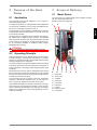
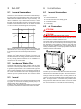
The heat pump is of compact design and is supplied complete
with the components listed below.
The air-to-water heat pump is designed for use in existing or
newly built heating systems.
R404A is used as the refrigerant.
It is designed exclusively for heating domestic and heating water!
The heat pump is suitable for mono energy and bivalent operation down to an external temperature of -20 °C.
English
Proper defrosting of the evaporator is guaranteed by maintaining
a heating water return flow temperature of more than 18 °C during continuous operation.
The heat pump is not designed for the increased heat consumption required when a building is being dried out. The additional
heat consumption should be met using special devices provided
by the customer. If a building is to be dried out in autumn or winter, we recommend installing an additional heating element
(available as an accessory).
ATTENTION!
The device is not suitable for operation with a frequency converter.
2.2
Operating Principle
Outside air is drawn in by the ventilator and fed via the evaporator (heat exchanger). The evaporator cools the air, i.e. it extracts
heat from it. This extracted heat is then transferred to the working
medium (refrigerant) in the evaporator.
The heat is “pumped” to a higher temperature level by increasing
its pressure with the aid of the electrically driven compressors. It
is then transferred to the heating water using the liquifier (heat
exchanger).
Electrical energy is used to raise the temperature of the heat in
the environment to a higher level. Because the energy extracted
from the air is transferred to the heating water, this type of device
is called an air-to-water heat pump.
The air-to-water heat pump consists of the main components
evaporator, ventilator and expansion valve, as well as the lownoise compressors, liquifier and electrical control system.
At low ambient temperatures, humidity accumulates on the evaporator in the form of frost reducing the transfer of heat. The evaporator is defrosted automatically by the heat pump as required.
Steam may be emitted from the air outlet depending on the atmospheric conditions.
www.dimplex.de
1)
Evaporator
2)
Check valve
3)
Ventilator
4)
Switch box
5)
Controllers
6)
Filter dryer
7)
Liquifier
8)
Expansion valve
9)
Compressor
E-3
3.2
3.2
Switch Box
The switch box is located in the heat pump. It can be swung out
after removing the lower front cover and loosening the fastening
screw located in the upper right-hand corner.
The switch box contains the supply connection terminals, as well
the power contactors, the soft starter unit and the heat pump
manager.
3.3
Heat Pump Controller
4
Transport
ATTENTION!
When transporting the heat pump, ensure that it is not tilted more than
45° (in any direction).
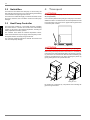
Use a wooden pallet for transporting the heat pump to the final installation location. The basic device can be transported with a lift
truck, hand truck or by means of 3/4" pipes fed through the holes
in the base plate or frame.
English
The heat pump manager is a convenient electronic regulation
and control device. It controls and monitors the entire heating
system on the basis of the external temperature, including hot
water preparation and safety systems.
The customer must install the external temperature sensor,
which is included in the scope of supply of the heat pump controller together with the necessary fixing accessories.
The enclosed operating instructions describe the function and
use of the heat pump manager.
ATTENTION!
The heat pump and transport pallet are only joined by the packing film.
Before using the transport holes in the frame, it is necessary to
remove the lower side panel assemblies. This is done by loosening each of the two screws at the base and then withdrawing the
panels by unhooking them from above. Rehang the panels by
gently pushing them in an upwards direction.
Opening the cover
Closing the cover
Be careful not to damage any components when inserting the
pipes through the frame.
E-4
6.2
5.1
Set-UP
6
General Information
Installation
6.1
The unit must be installed indoors on a level, smooth and horizontal surface. The entire base of the frame should lie directly on
the floor to ensure a good soundproof seal. If this is not the case,
additional sound insulation measures may be necessary. If the
device is installed on top of a built-under buffer tank, a surface
that fully supports the base is required. The heat pump must be
installed so that maintenance work can be carried out without
being hindered. This can be ensured by maintaining a clearance
of 1 m in front and to the left and right of the heat pump.
General Information
The following connections need to be established on the heat
pump:
Fresh and exhaust air
Flow and return flow of the heating system
Condensate outflow
Power supply
6.2
Air Connection
English
5
ATTENTION!
P
Do not restrict or block the area around the air intake or outlet.
ATTENTION!
P
P
Only operate the heat pump with the air ducts connected.
The glass fibre reinforced concrete air ducts offered as accessories are moisture-resistant and diffusion-free.
P
Never install the device in rooms subject to high humidity. Condensation can form on the heat pump and air circuit if the humidity exceeds 50% and the external temperature is below
O °C.
The sealing collar is used to seal the air ducts on the heat pump.
The air ducts are not screwed directly onto the heat pump. Only
the rubber seal comes into direct contact with the heat pump
when the system is installed correctly. This guarantees easy assembly and disassembly of the heat pump and also ensures that
solid-borne sound is well insulated.
If the heat pump is installed on an upper storey, the load-bearing
capacity of the ceiling should be checked. On account of the
acoustics, measures for isolating possible vibrations should also
be very carefully planned in advance as well. Installation on a
wooden floor is not recommended.
5.2
Condensed Water Pipe
Condensed water that forms during operation must be drained
off frost-free. The heat pump must be mounted on a level plane
to guarantee proper drainage. The condensed water pipe must
have a minimum diameter of 50 mm and should be fed frost-free
into a sewer. Condensate should not be discharged directly into
clearing tanks and cesspits because the aggressive vapours
could destroy the evaporator.
5.3
Sound
To prevent solid-borne sound from being transmitted to the heating system, we recommend connecting the heat pump to the
heating system using a flexible hose.
If another type of air duct is used, observe the external and internal dimensions as specified in the figure. Also ensure that the vibration and duct insulation are adequate.
If flange-mounted air ducts are used, connecting stubs are secured on the air inlet and air outlet sides of the evaporator with 4
M8 x 16 hexagon bolts in the threaded holes provided. When
doing this, ensure that both air duct stubs only touch the insulation. There should be no contact with the external sheeting.
Installed air ducts should be sound-isolated from the heat pump
to prevent the transmission of solid-borne sound to the ducts.
www.dimplex.de
E-5
6.3
Antifreeze
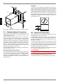
A method of manual drainage (see illustration) should be provided for heat pumps which are exposed to frost. The antifreeze
function of the heat pump controller is active whenever the controller and the heat circulating pump are ready for operation. If
the heat pump is taken out of service or in the event of a power
failure, the system has to be drained. The heating circuit should
be operated with a suitable antifreeze if heat pump systems are
implemented in buildings where a power failure can not be detected (holiday home).
0 [ PD[
PD[
English
P
PLQ LQ
The values in parentheses are valid for the LI 24TEL/ LI 28TEL
6.3
Heating System Connection
The heating system connections on the heat pump have a 1 1/4"
external thread. Use a spanner to firmly grip the transitions when
connecting the heat pump.
6.4
Electrical Connection
The power supply and control voltage are supplied using standard cables (load: 4-core, control: 3-core).
Before connecting the heating water system to the heat pump,
the heating system must be flushed to remove any impurities,
residue from sealants, etc. Any accumulation of deposits in the
liquifier could cause the heat pump to completely break down.
For systems in which the heating water flow can be shut off via
the radiator or thermostat valves, an overflow valve must be installed in a heating bypass behind the heat pump by the customer. This ensures a minimum heating water flow rate through
the heat pump and helps to avoid faults.
For detailed instructions on how to connect the external components and how the heat pump controller functions, please refer to
the device connection diagram and the operating manual supplied with the controller.
Once the heating system has been installed, it must be filled, deaerated and pressure-tested.
Ensure that the incoming supply has a clockwise rotating field
when connecting multiphase devices L1; L2; L3.
Minimum heating water flow rate
The minimum heating water flow rate through the heat pump
must be assured in all operating states of the heating system.
This can be accomplished, for example, by installing either a
manifold without differential pressure or an overflow valve. The
procedure for adjusting an overflow valve is described in the
Chapter Start-Up.
E-6
An all-pole disconnecting device with a contact gap of at least
3 mm (e.g. utility blocking contactor or power contactor) as well
as a 3-pole circuit breaker with common tripping for all external
conductors must be installed in the power supply (tripping current
in compliance with the Device Information).
ATTENTION!
Ensure that there is a clockwise rotating field: Operating the compressor
in the wrong rotational direction could cause damage to the compressor.
The control voltage must be protected by a 10 A fuse.
For detailed information, see Circuit Diagrams in the Appendix.
7.3
Start-UP
7.1
Any faults occurring during operation are also displayed on the
heat pump controller and can be corrected as described in the
operating instructions of the heat pump controller.
General Information
To ensure that start-up is performed correctly, it should only be
carried out by an after-sales service technician authorised by the
manufacturer. This may be a condition for extending the guarantee (see Warranty Service).
7.2
Preparation
The following items need to be checked prior to start-up:
All of the heat pump connections must be established as described in Chapter 6.
For external temperatures below 10 °C and heating water temperatures below 16 °C, the buffer tank should be heated up with
the 2nd heat generator to at least 25 °C.
Observe the following procedure to implement a smooth start-up:
1)
Close all of the heating circuits.
2)
Fully open the overflow valve.
3)
Use the controller to select the automatic operating mode.
4)
Wait until the buffer tank has reached a temperature of at
least 25 °C.
5)
Now slowly reopen the heating circuit valves in succession
so that the heating water throughput is constantly raised by
slightly opening the respective heating circuit. The heating
water temperature in the buffer tank must not be allowed to
drop below 20 °C during this process. This ensures that the
heat pump can be de frosted at any time.
6)
Set the minimum volume flow quantity on the overflow valve
and heat circulating pump when all heating circuits are fully
open and a heating water temperature in the buffer tank of
approx. 20 °C is maintained.
7)
New buildings have an increased heat consumption on account of the energy required to dry them out. This increased
heat consumption means that marginally dimensioned heating systems can not always achieve the desired room temperature. In such cases, we recommend keeping a 2nd heat
generator on standby during the first heating period. The
limit temperature on the heat pump controller should also be
turned up to 15 °C.
All valves that could impair the proper flow of the heating
water in the heating circuit must be open.
The air intake and air outlet paths must be clear.
The ventilator must turn in the direction indicated by the arrow.
The settings of the heat pump controller must be adapted to
the heating system in accordance with the controller’s operating instructions.
Ensure the condensate outflow functions.
7.3
Procedure
The heat pump is started up via the heat pump controller. Adjustments should be made in compliance with the instructions.
If an overflow valve is fitted to maintain the minimum heating
water flow rate, the valve must be adapted to the requirements of
the heating system. Incorrect adjustment can lead to faulty operation and increased energy consumption. We recommend carrying out the following procedure to correctly adjust the overflow
valve:
Close all of the heating circuits that may also be closed during
operation (depending on the type of heat pump usage) so that
the most unfavourable operating state - with respect to the water
flow rate - is achieved. This normally means the heating circuits
of the rooms on the south and west sides of the building. At least
one heating circuit must remain open (e.g. bathroom).
The overflow valve should be opened far enough to produce the
maximum temperature spread between the heating flow and return flow listed in the following table for the current heat source
temperature. The temperature spread should be measured as
close as possible to the heat pump. The heating element of mono
energy systems should be disconnected.
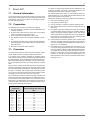
Heat source
temperature
Max. temperature spread
between heating flow and return
flow
From
To
-20 °C
-15 °C
4K
-14 °C
-10 °C
5K
-9 °C
-5 °C
6K
-4 °C
0 °C
7K
8K
1 °C
5 °C
6 °C
10 °C
9K
11 °C
15 °C
10 K
16 °C
20 °C
11 K
21 °C
25 °C
12 K
26 °C
30 °C
13 K
31 °C
35 °C
14 K
www.dimplex.de
E-7
English
7
8
8
Maintenance / Cleaning
8.1
Maintenance
To protect the paintwork, avoid leaning or putting objects on the
device. External heat pump parts can be wiped with a damp cloth
and domestic cleaner.
ATTENTION!
Never use cleaning agents containing sand, soda, acid or chloride as
these can damage the surfaces.
English
To prevent faults due to sediment in the heat exchanger of the
heat pump, ensure that the heat exchanger in the heating system
can not be contaminated. We recommend protecting the evaporator by installing a bird guard in the inlet duct. At least 80% of the
cross section of the grating should be open. In the event that operating malfunctions due to contamination still occur, the system
should be cleaned as described below.
8.2
Cleaning the Heating System
The ingress of oxygen into the heating water circuit may result in
the formation of oxidation products (rust), particularly if steel
components are used. These products enter the heating system
via the valves, the circulating pumps and/or plastic pipes. It is
therefore essential - in particular with respect to the piping of underfloor heating systems - that only diffusion-proof materials are
used.
ATTENTION!
We recommend the installation of a suitable corrosion protection system
to prevent the formation of deposits (e.g. rust) in the condenser of the
heat pump.
Residue from lubricants and sealants may also contaminate the
heating water.
In the case of severe contamination leading to a reduction in the
performance of the liquifier in the heat pump, the system must be
cleaned by a heating technician.
According to today's state of knowledge, we recommend using a
5 % phosphoric acid solution for cleaning purposes. However, if
cleaning needs to be performed more frequently, a 5 % formic
acid solution should be used.
In either case, the cleaning fluid should be at room temperature.
We recommend flushing the heat exchanger in the direction opposite to the normal flow direction.
To prevent acidic cleaning agents from entering the heating system circuit, we recommend connecting the flushing device directly to the flow and return flow of the liquifier of the heat pump.
It is important that the system be thoroughly flushed using appropriate neutralising agents to prevent any damage from being
caused by cleaning agent residue remaining in the system.
Acids must be used with great care and all relevant regulations of
the employers' liability insurance associations must be adhered
to.
If in doubt, contact the manufacturer of the chemicals!
E-8
8.3
Cleaning the Air System
Air ducts, evaporator, ventilator and condensate outflow should
be cleaned of contamination (leaves, twigs, etc.) before the heating period. Do this by opening the front of the heat pump. The
bottom should be opened first followed by the top.
ATTENTION!
Before opening the device, ensure that all circuits are isolated from the
power supply.
Remove and rehang the side panel assemblies as described in
Chapter 4.
To prevent the evaporator and the condensate tray from being
damaged, do not use hard or sharp objects for cleaning.
9
Faults / TroubleShooting
This heat pump is a quality product and is designed for troublefree and maintenance-free operation. In the event that a fault
should occur, it will be shown on the heat pump manager display.
Simply consult the Faults and Trouble-shooting page in the operating instructions of the heat pump manager. If you cannot correct the fault yourself, please contact your after-sales service
technician.
ATTENTION!
Any work on the heat pump may only be performed by authorised and
qualified after-sales service technicians.
10 Decommissioning/
Disposal
Before removing the heat pump, disconnect it from the power
source and close all valves. Observe all environmentally-relevant
requirements regarding the recovery, recycling and disposal of
materials and components in accordance with all applicable
standards. Particular attention should be paid to the proper disposal of refrigerants and refrigeration oils.
11
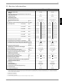
11 Device Information
1
2
Type and order code
Design
2.1
Degree of protection according to EN 60 529 for compact devices
and heating components
2.2
Installation location
3
Performance data
3.1
Operating temperature limits:
3.2
3.3
Heating water flow/return flow 1
°C / °C
Air
°C
Heat output / COP
at A-7 / W35
at A-7 / W45 2
at A2 / W35 2
at A7 / W35 2
at A7 / W45 2
kW / ---
kW / ---
kW / ---
kW / ---
kW / ---
LI 24TEL
IP 21
IP 21
Indoors
Indoors
Up to 58 / above 18
Up to 58 / above 18
-25 to +35
Temperature spread of heating water (flow/return flow) at A7 / W35K
2
LI 20TEL
kW / ---
-25 to +35
9.8
5.0
9.7
5.0
3
7.1 / 2.8
6.7 / 2.6
8.9 / 2.6
8.8 / 2.5
4
12.7 / 2.8
11.7 / 2.6
16.1 / 2.7
15.5 / 2.4
3
6.2 / 2.3
8.4 / 2.2
4
11.1 / 2.2
14.4 / 2.1
3
9.3 / 3.2
8.6 / 3.1
10.9 / 3.0
10.5 / 3.0
4
14.9 / 3.1
14.6 / 3.0
19.2 / 3.2
18.7 / 3.1
3
10.7 / 3.7
10.4 / 3.5
13.1 / 3.4
12.6 / 3.3
4
17.1 / 3.5
17.0 / 3.4
24.8 / 3.6
24.2 / 3.4
3
10.1 / 3.0
4
at A10 / W35 2
12.1 / 2.9
16.6 / 2.9
23.7 / 2.9
3
12.8 / 4.0
12.6 / 3.8
14.1 / 3.5
13.8 / 3.4
4
20.0 / 3.8
19.5 / 3.7
26.6 / 3.8
25.4 / 3.6
3.4
Sound power level device / outdoors
dB(A)
58 / 64
62 / 68
3.5
Sound pressure level at a distance of 1 m (indoors)
dB(A)
54
58
3.6
Heating water flow with an internal pressure differential of m³/h / Pa
3.7
Air flow rate with an external static pressure differential of m³/h / Pa
3.8
Refrigerant; total filling weight
4
Dimensions, connections and weight
8000 / 25
R404A / 4.2
H x W x L cm
Inch
4.3
Air duct inlet and outlet (min. internal dimensions)
L x W cm
4.4
Weight of the transportable unit(s) incl. packing
kg
5
Electrical Connection
5.1
Nominal voltage; fuse protection
V/A
5.2
Nominal power consumption 2 A2 W35
kW
5.3
Starting current with soft starter
A
5.4
Nominal current A2 W35 / cosϕ
A / ---
6
7
Complies with the European safety regulations
Additional model features
7.1
Defrosting
Type of defrosting
Defrosting tray included
Performance levels
7.4
Controller internal/external
4.5 / 22700
9000 / 0
5500 / 25
Device dimensions
7.3
2.3 / 5900
R404A / 3.7
Device connections to heating system
Heating water in device protected against icing
3.3 / 12300
6600 / 0
type / kg
4.1
7.2
1.8 / 3700
m³/h / Pa
4.2
6
English
Device information for air-to-water heat pumps (heating only) LI 20TEL - LI 24TEL
157 x 75 x 88
171 x 75 x 103
G 1 1/4'' external
G 1 1/4'' external
65 x 65
72.5 x 72.5
255
310
400 / 20 T
4.80
400 / 25 T
4.89
6.05
6.11
23
8.7 / 0.8
24
8.8 / 0.8
5
10.9 / 0.8
11.0 / 0.8
5
Automatic
Automatic
Reverse cycle
Reverse cycle
Yes (heated)
Yes (heated)
Yes
Yes
2
2
Internal
Internal
1. See operating limits diagram
2. This data indicates the size and capacity of the system. For an analysis of the economic and energy efficiency of the system, other parameters, such as, in particular, the defrosting
capacity, the bivalence point and regulation, should also be taken into consideration. The specified values, e.g. A2 / W55, have the following meaning: 2 °C external air temperature
and 55 °C heating water flow temperature.
3. Operation with 1 compressors
4. Operation with 2 compressors
5. See CE declaration of conformity
6. The heat circulating pump and the heat pump controller must always be ready for operation.
www.dimplex.de
E-9
11
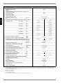
Device information for air-to-water heat pumps (heating only) LI 28TEL
1
2
Type and order code
Design
2.1
Degree of protection according to EN 60 529 for compact devices
and heating components
2.2
Installation location
3
Performance data
3.1
Operating temperature limits:
English
3.2
LI 28TEL
IP 21
Indoors
Heating water flow/return flow 1
°C / °C
Air
°C
Up to 58 / above 18
-25 to +35
Temperature spread of heating water (flow/return flow) at A7 / W35K
3.3
Heat output / COP
at A-7 / W35
2
at A-7 / W45 2
at A2 / W35 2
at A7 / W35 2
at A7 / W45
2
kW / ---
kW / ---
kW / ---
kW / ---
kW / ---
9.9
5.0
3
9.9 / 2.4
9.2 / 2.3
4
19.1 / 2.7
16.1 / 2.3
3
8.7 / 2.0
4
15.0 / 1.9
3
12.8 / 3.0
4
22.3 / 3.0
22.2 / 3.0
3
14.2 / 3.1
13.9 / 3.1
4
25.8 / 3.4
25.1 / 3.3
12.6 / 3.0
3
12.8 / 2.9
4
at A10 / W35 2
kW / ---
24.6 / 2.8
3
14.7 / 3.1
4
29.1 / 3.6
14.3 / 3.2
28.7 / 3.5
3.4
Sound power level device / outdoors
dB(A)
62 / 68
3.5
Sound pressure level at a distance of 1 m (indoors)
dB(A)
58
3.6
Heating water flow with an internal pressure differential of m³/h / Pa
3.7
Air flow rate with an external static pressure differential of m³/h / Pa
3.8
Refrigerant; total filling weight
4
Dimensions, connections and weight
m³/h / Pa
8000 / 25
R404A / 4.3
Device dimensions
H x W x L cm
4.2
Device connections to heating system
Inch
4.3
Air duct inlet and outlet (min. internal dimensions)
L x W cm
4.4
Weight of the transportable unit(s) incl. packing
kg
5
Electrical Connection
5.1
Nominal voltage; fuse protection
V/A
5.2
Nominal power consumption 2 A2 W35
kW
5.3
Starting current with soft starter
A
5.4
Nominal current A2 W35 / cosϕ
A / ---
6
7
Complies with the European safety regulations
Additional model features
7.1
Defrosting
Performance levels
7.4
Controller internal/external
72.5 x 72.5
314
400 / 25 T
7.40
7.44
25
13.4 / 0.8
13.4 / 0.8
5
Reverse cycle
Defrosting tray included
Heating water in device protected against icing
171 x 75 x 103
G 1 1/4'' external
Automatic
Type of defrosting
7.3
4.6 / 12000
9000 / 0
type / kg
4.1
7.2
2.3 / 3100
Yes (heated)
6
Yes
2
Internal
1. See operating limits diagram
2. This data indicates the size and capacity of the system. For an analysis of the economic and energy efficiency of the system, other parameters, such as, in particular, the defrosting
capacity, the bivalence point and regulation, should also be taken into consideration. The specified values, e.g. A2 / W55, have the following meaning: 2 °C external air temperature
and 55 °C heating water flow temperature.
3. Operation with 1 compressors
4. Operation with 2 compressors
5. See CE declaration of conformity
6. The heat circulating pump and the heat pump controller must always be ready for operation.
E-10
Anhang / Appendix / Annexes
1
Maßbilder / Dimension Drawings / Schémas cotés................................................................... A-II
1.1 Maßbild / Dimension Drawing / Schéma coté LI 20TEL ......................................................................... A-II
1.2 Maßbild / Dimension Drawing / Schéma coté LI 24TEL / LI 28TEL....................................................... A-III
2
Diagramme / Diagrams / Diagrammes ....................................................................................... A-IV
2.1 Kennlinien / Characteristic curves / Courbes caractéristiques LI 20TEL ...............................................A-IV
2.2 Kennlinien / Characteristic curves / Courbes caractéristiques LI 24TEL ................................................A-V
2.3 Kennlinien / Characteristic curves / Courbes caractéristiques LI 28TEL ...............................................A-VI
Stromlaufpläne / Circuit Diagrams / Schémas électriques..................................................... A-VII
3.1
3.2
3.3
3.4
4
Steuerung / Control / Commande .........................................................................................................A-VII
Last / Load / Charge ............................................................................................................................A-VIII
Anschlussplan / Circuit Diagram / Schéma électrique ...........................................................................A-IX
Legende / Legend / Légende..................................................................................................................A-X
Hydraulische Prinzipschemen / Hydraulic Plumbing Diagrams / Schémas hydrauliques ... A-XI
4.1 Monoenergetische Anlage / Mono energy system / Installation mono-énergétique ..............................A-XI
4.2 Monoenergetische Anlage und Warmwasserbereitung / Mono energy system and domestic hot water
preparation / Installation mono-énergétique et production d´eau chaude ............................................A-XII
4.3 Bivalente Anlage / Bivalent system / Installation bivalente ..................................................................A-XIII
4.4 Legende / Legend / Légende.............................................................................................................. A-XIV
5
Konformitätserklärung / Declaration of Conformity / Déclaration de conformité ................A-XV
www.dimplex.de
A-I
Anhang · Appendix · Annexes
3
A-II
%HGLHQVHLWH
2SHUDWLQJVLGH
&{WpGHFRPPDQGH
/XIWULFKWXQJ
'LUHFWLRQRIDLUIORZ
6HQVG
pFRXOHPHQWDLU
.RQGHQVDWDEODXIVFKODXFK
&RQGHQVDWHRXWIORZKRVH
7X\DXHDXGHFRQGHQVDWLRQ
/XIWULFKWXQJ
'LUHFWLRQRIDLUIORZ
6HQVG
pFRXOHPHQWDLU
+HL]XQJVDQVFKOXVV
+HDWLQJFRQQHFWLRQ
5DFFRUGHPHQWFKDXIIDJH
+HL]XQJVUFNODXI
(LQJDQJLQGLH:3
´$XHQJHZLQGH
+HDWLQJZDWHUUHWXUQIORZ
+HDWSXPSLQOHW
´H[WHUQDOWKUHDG
5HWRXUHDXGHFKDXIIDJH
(QWUpHGDQVOD3$&
)LOHWDJHH[WpULHXU´
/XIWULFKWXQJ
'LUHFWLRQRIDLUIORZ
6HQVG
pFRXOHPHQWDLU
(OHNWUROHLWXQJHQ
(OHFWULFOLQHV
/LJQHVpOHFWULTXHV
.RQGHQVDWDEODXI
,QQHQ¡PP
&RQGHQVDWHRXWIORZ
LQVLGH¡PP
(FRXOHPHQWGXFRQGHQVDW
¡LQWPP
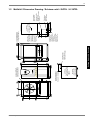
1.1
+HL]XQJVYRUODXI
$XVJDQJDXVGHU:3
´$XHQJHZLQGH
+HDWLQJZDWHUIORZ
+HDWSXPSRXWOHW
´H[WHUQDOWKUHDG
$OOHUHDXGHFKDXIIDJH
6RUWLHGHOD3$&
)LOHWDJHH[WpULHXU´
[,QQHQJHZLQGH0[
[LQWHUQDOWKUHDG0[
[ILOHWDJHLQWpULHXU0[
Anhang · Appendix · Annexes
[,QQHQJHZLQGH0[
[LQWHUQDOWKUHDG0[
[ILOHWDJHLQWpULHXU0[
1
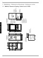
1 Maßbilder / Dimension Drawings / Schémas cotés
Maßbild / Dimension Drawing / Schéma coté LI 20TEL
www.dimplex.de
%HGLHQVHLWH
2SHUDWLQJVLGH
&{WpGHFRPPDQGH
+HL]XQJVDQVFKOXVV
+HDWLQJFRQQHFWLRQ
5DFFRUGHPHQWFKDXIIDJH
Anhang · Appendix · Annexes
/XIWULFKWXQJ
'LUHFWLRQRIDLUIORZ
6HQVG
pFRXOHPHQWDLU
.RQGHQVDWDEODXIVFKODXFK
&RQGHQVDWHRXWIORZKRVH
7X\DXHDXGHFRQGHQVDWLRQ
+HL]XQJVUFNODXI
(LQJDQJLQGLH:3
´$XHQJHZLQGH
+HDWLQJZDWHUUHWXUQIORZ
+HDWSXPSLQOHW
´H[WHUQDOWKUHDG
5HWRXUHDXGHFKDXIIDJH
(QWUpHGDQVOD3$&
)LOHWDJHH[WpULHXU´
+HL]XQJVYRUODXI
$XVJDQJDXVGHU:3
´$XHQJHZLQGH
+HDWLQJZDWHUIORZ
+HDWSXPSRXWOHW
´H[WHUQDOWKUHDG
$OOHUHDXGHFKDXIIDJH
6RUWLHGHOD3$&
)LOHWDJHH[WpULHXU´
/XIWULFKWXQJ
'LUHFWLRQRIDLUIORZ
6HQVG
pFRXOHPHQWDLU
[,QQHQJHZLQGH0[
[LQWHUQDOWKUHDG0[
[ILOHWDJHLQWpULHXU0[
(OHNWUROHLWXQJHQ
(OHFWULFOLQHV
/LJQHVpOHFWULTXHV
.RQGHQVDWDEODXI
,QQHQ¡PP
&RQGHQVDWHRXWIORZ
LQVLGH¡PP
(FRXOHPHQWGXFRQGHQVDW
¡LQWPP
1.2
/XIWULFKWXQJ
'LUHFWLRQRIDLUIORZ
6HQVG
pFRXOHPHQWDLU
[,QQHQJHZLQGH0[
[LQWHUQDOWKUHDG0[
[ILOHWDJHLQWpULHXU0[
1.2
Maßbild / Dimension Drawing / Schéma coté LI 24TEL / LI 28TEL
A-III
2
2 Diagramme / Diagrams / Diagrammes
2.1
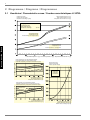
Kennlinien / Characteristic curves / Courbes caractéristiques LI 20TEL
:DVVHUDXVWULWWVWHPSHUDWXULQ>&@
:DWHURXWOHWWHPSHUDWXUHLQ>&@
7HPSpUDWXUHGHVRUWLHGHO
HDXHQ>&@
+HL]OHLVWXQJLQ>N:@
+HDWLQJFDSDFLW\LQ>N:@
3XLVVDQFHGHFKDXIIDJHHQ>N:@
%HGLQJXQJHQÂ&RQGLWLRQVÂ&RQGLWLRQV
+HL]ZDVVHUGXUFKVDW]
+HDWLQJZDWHUIORZUDWH
'pELWG
HDXGHFKDXIIDJH
PK
9HUGLFKWHU%HWULHE
FRPSUHVVRUPRGH
)RQFWLRQQHPHQWjFRPSUHVVHXUV
Anhang · Appendix · Annexes
9HUGLFKWHU%HWULHE
FRPSUHVVRUPRGH
)RQFWLRQQHPHQWjFRPSUHVVHXU
/XIWHLQWULWWVWHPSHUDWXULQ>&@Â$LULQOHWWHPSHUDWXUHLQ>&@Â7HPSpUDWXUHG
HQWUpHG
DLUHQ>&@
/HLVWXQJVDXIQDKPHLQFO3XPSHQOHLVWXQJVDQWHLO
3RZHUFRQVXPSWLRQLQFOSRZHULQSXWWRSXPS
&RQVRPPDWLRQGHSXLVVDQFH\FRPSULVSDUWGHFRQVRPPDWLRQGHODSRPSH
'UXFNYHUOXVWLQ>3D@
3UHVVXUHORVVLQ>3D@
3HUWHGHSUHVVLRQHQ>3D@
9HUIOVVLJHU
&RQGHQVHU
&RQGHQVHXU
/XIWHLQWULWWVWHPSHUDWXULQ>&@
$LULQOHWWHPSHUDWXUHLQ>&@
7HPSpUDWXUHG
HQWUpHG
DLUHQ>&@
/HLVWXQJV]DKOLQFO3XPSHQOHLVWXQJVDQWHLO
&RHIILFLHQWRISHUIRUPDQFHLQFOSRZHULQSXWWRSXPS
&RHIILFLHQWGHSHUIRUPDQFH\FRPSULVSDUWGHFRQVRPPDWLRQGHODSRPSH
9HUGLFKWHU%HWULHE
FRPSUHVVRUPRGH
)RQFWLRQQHPHQWj
FRPSUHVVHXU
/XIWHLQWULWWVWHPSHUDWXULQ>&@
$LULQOHWWHPSHUDWXUHLQ>&@
7HPSpUDWXUHG
HQWUpHG
DLUHQ>&@
A-IV
+HL]ZDVVHUGXUFKIOXVVLQ>PK@
+HDWLQJZDWHUIORZUDWHLQ>PK@
'pELWG
HDXGHFKDXIIDJHHQ>PK@
2.2
2.2
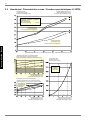
Kennlinien / Characteristic curves / Courbes caractéristiques LI 24TEL
:DVVHUDXVWULWWVWHPSHUDWXULQ>&@
:DWHURXWOHWWHPSHUDWXUHLQ>&@
7HPSpUDWXUHGHVRUWLHGHO
HDXHQ>&@
+HL]OHLVWXQJLQ>N:@
+HDWLQJFDSDFLW\LQ>N:@
3XLVVDQFHGHFKDXIIDJHHQ>N:@
%HGLQJXQJHQÂ&RQGLWLRQVÂ&RQGLWLRQV
+HL]ZDVVHUGXUFKVDW]
+HDWLQJZDWHUIORZUDWH
'pELWG
HDXGHFKDXIIDJH
PK
9HUGLFKWHU%HWULHE
FRPSUHVVRUPRGH
)RQFWLRQQHPHQWjFRPSUHVVHXUV
Anhang · Appendix · Annexes
9HUGLFKWHU%HWULHE
FRPSUHVVRUPRGH
)RQFWLRQQHPHQWjFRPSUHVVHXU
/XIWHLQWULWWVWHPSHUDWXULQ>&@Â$LULQOHWWHPSHUDWXUHLQ>&@Â7HPSpUDWXUHG
HQWUpHG
DLUHQ>&@
/HLVWXQJVDXIQDKPHLQFO3XPSHQOHLVWXQJVDQWHLO
3RZHUFRQVXPSWLRQLQFOSRZHULQSXWWRSXPS
&RQVRPPDWLRQGHSXLVVDQFH\FRPSULVSDUWGHFRQVRPPDWLRQGHODSRPSH
'UXFNYHUOXVWLQ>3D@
3UHVVXUHORVVLQ>3D@
3HUWHGHSUHVVLRQHQ>3D@
9HUIOVVLJHU
&RQGHQVHU
&RQGHQVHXU
/XIWHLQWULWWVWHPSHUDWXULQ>&@
$LULQOHWWHPSHUDWXUHLQ>&@
7HPSpUDWXUHG
HQWUpHG
DLUHQ>&@
/HLVWXQJV]DKOLQFO3XPSHQOHLVWXQJVDQWHLO
&RHIILFLHQWRISHUIRUPDQFHLQFOSRZHULQSXWWRSXPS
&RHIILFLHQWGHSHUIRUPDQFH\FRPSULVSDUWGHFRQVRPPDWLRQGHODSRPSH
9HUGLFKWHU%HWULHE
FRPSUHVVRUPRGH
)RQFWLRQQHPHQWj
FRPSUHVVHXU
/XIWHLQWULWWVWHPSHUDWXULQ>&@
$LULQOHWWHPSHUDWXUHLQ>&@
7HPSpUDWXUHG
HQWUpHG
DLUHQ>&@
www.dimplex.de
+HL]ZDVVHUGXUFKIOXVVLQ>PK@
+HDWLQJZDWHUIORZUDWHLQ>PK@
'pELWG
HDXGHFKDXIIDJHHQ>PK@
A-V
2.3
2.3
Kennlinien / Characteristic curves / Courbes caractéristiques LI 28TEL
:DVVHUDXVWULWWVWHPSHUDWXULQ>&@
:DWHURXWOHWWHPSHUDWXUHLQ>&@
7HPSpUDWXUHGHVRUWLHGHO
HDXHQ>&@
+HL]OHLVWXQJLQ>N:@
+HDWLQJFDSDFLW\LQ>N:@
3XLVVDQFHGHFKDXIIDJHHQ>N:@
%HGLQJXQJHQÂ&RQGLWLRQVÂ&RQGLWLRQV
+HL]ZDVVHUGXUFKVDW]
+HDWLQJZDWHUIORZUDWH
'pELWG
HDXGHFKDXIIDJH
PK
9HUGLFKWHU%HWULHE
FRPSUHVVRUPRGH
)RQFWLRQQHPHQWjFRPSUHVVHXUV
9HUGLFKWHU%HWULHE
FRPSUHVVRUPRGH
)RQFWLRQQHPHQWjFRPSUHVVHXU
Anhang · Appendix · Annexes
/XIWHLQWULWWVWHPSHUDWXULQ>&@Â$LULQOHWWHPSHUDWXUHLQ>&@Â7HPSpUDWXUHG
HQWUpHG
DLUHQ>&@
/HLVWXQJVDXIQDKPHLQFO3XPSHQOHLVWXQJVDQWHLO
3RZHUFRQVXPSWLRQLQFOSRZHULQSXWWRSXPS
&RQVRPPDWLRQGHSXLVVDQFH\FRPSULVSDUWGHFRQVRPPDWLRQGHODSRPSH
'UXFNYHUOXVWLQ>3D@
3UHVVXUHORVVLQ>3D@
3HUWHGHSUHVVLRQHQ>3D@
9HUIOVVLJHU
&RQGHQVHU
&RQGHQVHXU
/XIWHLQWULWWVWHPSHUDWXULQ>&@
$LULQOHWWHPSHUDWXUHLQ>&@
7HPSpUDWXUHG
HQWUpHG
DLUHQ>&@
/HLVWXQJV]DKOLQFO3XPSHQOHLVWXQJVDQWHLO
&RHIILFLHQWRISHUIRUPDQFHLQFOSRZHULQSXWWRSXPS
&RHIILFLHQWGHSHUIRUPDQFH\FRPSULVSDUWGHFRQVRPPDWLRQGHODSRPSH
9HUGLFKWHU%HWULHE
FRPSUHVVRUPRGH
)RQFWLRQQHPHQWj
FRPSUHVVHXU
/XIWHLQWULWWVWHPSHUDWXULQ>&@
$LULQOHWWHPSHUDWXUHLQ>&@
7HPSpUDWXUHG
HQWUpHG
DLUHQ>&@
A-VI
+HL]ZDVVHUGXUFKIOXVVLQ>PK@
+HDWLQJZDWHUIORZUDWHLQ>PK@
'pELWG
HDXGHFKDXIIDJHHQ>PK@
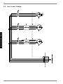
3.1
3 Stromlaufpläne / Circuit Diagrams / Schémas
électriques
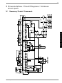
Steuerung / Control / Commande
Anhang · Appendix · Annexes
3.1
www.dimplex.de
A-VII
3.2
3.2
Anhang · Appendix · Annexes
A-VIII
Last / Load / Charge
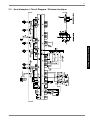
3.3
Anschlussplan / Circuit Diagram / Schéma électrique
Anhang · Appendix · Annexes
3.3
RGHUÂRUÂRX
www.dimplex.de
A-IX
3.4
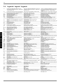
3.4
Legende / Legend / Légende
A1
Drahtbrücke einlegen wenn kein EVU-Sperrschütz benötigt wird (Eingang offen = EVU-Sperre
= Wärmepumpe „aus“)
Wire jumper must be inserted if no utility blocking
contactor is required (contact open = utility block =
heat pump "off").
A2
Drahtbrücke bei Nutzung des 2ten Sperreinganges
entfernen (Eingang offen = Wärmepumpe „aus“)
Drahtbrücke Störung Verdichter M1
Thermostat Warmwasser
Thermostat Schwimmbadwasser
Pressostat Abtauende
Düsenringheizung
2. Wärmeerzeuger Elektroheizung (Funktion ist
über Regler wählbar)
Sicherung für N1-Relaisausgänge an J12 und J13
4,0 ATr
Sicherung für N1-Relaisausgänge an J15 bis J18
4,0 ATr
Pressostat Hochdruck
Pressostat Niederdruck
Heißgasthermostat
Wicklungsschutz Ventilator
Leuchte Störfernanzeige (Relaisbaugruppe)
Remove if the second disable connector is used
(contact open = heat pump "off").
Wire jumper fault, M1 compressor
Hot water thermostat
Swimming pool water thermostat
Defrost end controller
Nozzle ring heater
2nd heat generator, electric heating (function
selectable via controller)
Fuse for N1 relay outputs at J12 and J13
4.0 slow-acting
Fuse for N1 relay outputs at J15 to J18
4.0 slow-acting
High-pressure switch
Low-pressure switch
Hot gas thermostat
Winding protection, ventilator
Remote fault indicator lamp (relay module)
Power supply N1 (24 V AC)
Low-voltage inputs/outputs
Signal inputs/outputs (230V AC)
Has no function
Socket for operating panel
Has no function
Relay outputs for the control of system components
K20*
K22*
K23*
M1
M2
M3
M13*
M15*
M16*
M18*
M19*
M21*
M22*
N1
N7
Stromversorgung-N1 (24V AC)
Niederspannungsein-/ausgänge
Signalein-/ausgänge (230V AC)
Ohne Funktion
Steckdose für Bedienteil
Ohne Funktion
Relaisausgänge zur Ansteuerung der Systemkomponenten
Schütz Verdichter 1
Schütz Ventilator
Schütz Verdichter 2
Elektron. Relais f. Störfernanzeige (Relaisbaugruppe)
Elektron. Relais f. Schwimmbadwasserumwälzpumpe (Relaisbaugruppe)
Schütz 2. Wärmeerzeuger
EVU-Sperrschütz
SPR-Hilfsrelais
Verdichter 1
Ventilator
Verdichter 2
Heizungsumwälzpumpe Hauptkreis
Heizungsumwälzpumpe 2. Heizkreis
Zusatzumwälzpumpe
Warmwasserumwälzpumpe
Schwimmbadwasserumwälzpumpe
Mischer Hauptkreis
Mischer 2. Heizkreis
Wärmepumpenregler
Sanftanlaufsteuerung Verdichter 1
Electron. relay for swimming pool water circulating
pump (relay module)
Contactor, suppl. heating system
Utility blocking contactor
SPR auxiliary relay
Compressor 1
Ventilator
Compressor 2
Heat circulating pump of the main circuit
Heat circulating pump for heating circuit 2
Auxiliary circulating pump
Hot water circulating pump
Swimming pool water circulating pump
Mixer for main circuit
Mixer for heating circuit 2
Heat pump controller
Soft start control for compressor 1
N8
Sanftanlaufsteuerung Verdichter 2
Soft start control for compressor 2
N14
R1
R2
R3
Operating element
External temperature sensor
Return flow sensor for heating system
Hot water sensor (as an alternative to the hot water
thermostat)
Sensor for heating circuit 2
Flow sensor
Safety isolating transformer 230/24 V AC-50 Hz/
28 VA
Terminal strip: load infeed 3L/PE 400VAC ~ 50Hz
X3
Y1
Bedienteil
Außentemperaturfühler
Rücklauffühler-Heizung
Warmwasserfühler (alternativ zum Warmwasserthermostat)
Fühler für den 2ten Heizkreislauf
Vorlauffühler
Sicherheitstrenntransformator 230/24 VAC-50Hz/
28VA
Klemmenleiste: Einspeisung Last
3L/PE 400VAC ~ 50Hz
Klemmenleiste: Einspeisung Steuerspannung
L/N/PE 230VAC ~ 50Hz
Klemmenleiste: Kleinspannung
Vier-Wege-Umschaltventil
Terminal strip: control voltage infeed L/N/PE
230 V AC ~ 50 Hz
Terminal strip: extra-low voltage
Four-way valve
Cavalier à fil à monter en absence de contacteur
de coupure du fournisseur d'énergie (pont ouvert =
coupure société électricité = pompe à chaleur
« arrêtée »)
Cavalier à fil à retirer si la 2e entrée de coupure est
utilisée (pont ouvert = pompe à chaleur « arrêtée »)
Cavalier dysfonctionnement compresseur M1
Thermostat eau chaude
Thermostat eau de piscine
Pressostat fin de dégivrage
Chauffage à couronne perforée
2e générateur de chaleur chauffage électrique
(fonction réglable par le régulateur)
Fusible pour sorties de relais N1 en J12 et J13
4,0 ATr
Fusible pour sorties de relais N1 en J15 jusqu’à J18
4,0 ATr
Pressostat haute pression
Pressostat basse pression
Thermostat gaz de chauffage
Blindage de l'enroulement ventilateur
Témoin de télédétection de pannes (sur module de
relais)
Alimentation en courant N1 (24 V AC)
Entrées et sorties de basse tension
Entrées et sorties de signaux (230 V AC)
Sans fonction
Prise pour le panneau de commande
Sans fonction
Sorties de relais pour la commande des composants du système
Contacteur compresseur 1
Contacteur ventilateur
Contacteur compresseur 2
Relais pour télédétection de pannes (sur module de
relais)
Relais pour circulateur d’eau de piscine (sur
module de relais)
Contacteur 2ème générateur de chaleur
Contacteur de coupure du fournisseur d'énergie
Relais auxiliaire « SPR »
Compresseur 1
Ventilateur
Compresseur 2
Circulateur de chauffage circuit principal
Circulateur de chauffage 2e circuit de chauffage
Circulateur supplémentaire
Circulateur d’eau chaude
Circulateur d’eau de piscine
Mélangeur circuit principal
Mélangeur 2e circuit de chauffage
Régulateur de pompe à chaleur
Commande de démarrage progressif pour compresseur 1
Commande de démarrage progressif pour compresseur 2
Commande
Sonde de température extérieure
Sonde retour chauffage
Sonde d’eau chaude (alternative au thermostat eau
chaude)
Sonde pour le 2e circuit de chauffage
Sonde aller
Transformateur sectionneur de sécurité 230/
24 VAC-50Hz/28VA
Bornier : alimentation puissance 3L/PE 400 VAC ~
50 Hz
Bornier : bornier tension de commande L/N/PE-230
V AC ~ 50Hz
Bornier : tension de sécurité
Vanne d’inversion 4 voies
EVU
SPR
MA
MZ
*
----–––––
Abkürzungen:
Energieversorgungsunternehmen
Sperre
Mischer AUF
Mischer ZU
Bauteile sind extern beizustellen
bauseits bei Bedarf anzuschließen
werksseitig verdrahtet
Abbreviations:
Utility company
Block
Mixer OPEN
Mixer CLOSED
Components to be supplied from external sources
To be connected by the customer as required
Wired ready for use
Abréviations :
Société de production et de distribution d'énergie
Blocage
Mélangeur OUVERT
Mélangeur FERME
Pièces à fournir par le client
à raccorder par le client au besoin
câblé départ usine
A4
B3*
B4*
E3
E4
E10*
F2
F3
F4
F5
F7
F23
H5*
J1
J2...J7
J8
J9
J10
J11
J12...J18
Anhang · Appendix · Annexes
K1
K2
K3
K11*
K12*
R5
R9
T1
X1
X2
A-X
Contactor for compressor 1
Contactor for ventilator
Contactor for compressor 2
Electron. remote fault indicator relay (relay module)
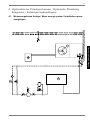
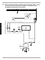
4.1
4 Hydraulische Prinzipschemen / Hydraulic Plumbing
Diagrams / Schémas hydrauliques
Monoenergetische Anlage / Mono energy system / Installation monoénergétique
Anhang · Appendix · Annexes
4.1
www.dimplex.de
A-XI
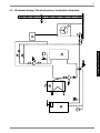
4.2
4.2
Anhang · Appendix · Annexes
A-XII
Monoenergetische Anlage und Warmwasserbereitung / Mono energy
system and domestic hot water preparation / Installation monoénergétique et production d´eau chaude
4.3
Bivalente Anlage / Bivalent system / Installation bivalente
Anhang · Appendix · Annexes
4.3
www.dimplex.de
A-XIII
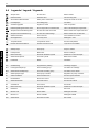
4.4
4.4
Legende / Legend / Légende
Absperrventil
Shutoff valve
Robinet d’arrêt
Überstromventil
Overflow valve
Vanne de trop-plein
Sicherheitsventilkombination
Safety valve combination
Groupe de valves de sécurité
Umwälzpumpe
Circulating pump
Circulateur
Ausdehnungsgefäß
Expansion vessel
Vase d´expansion
Raumtemperaturgesteuertes Ventil
Room temperature-controlled valve
Valve commandée par température
Absperrventil mit Rückschlagventil
Shutoff valve with check valve
Robinet d’arrêt avec clapet anti-retour
Absperrventil mit Entwässerung
Shutoff valve with drainage
Robinet d’arrêt avec écoulement
Wärmeverbraucher
Heat consumer
Consommateur de chaleur
Vierwegemischer
Four-way mixer
Mélangeur 4 voies
Temperaturfühler
Temperature sensor
Sonde de température
Flexibler Anschlussschlauch
Flexible connection hose
Tuyau de raccord flexible
Wärmepumpe
Heat pump
Pompe à chaleur
Pufferspeicher
Buffer tank
Réservoir tampon
Elektroverteilung
Electrical distribution system
Distributeur courant électrique
Warmwasserspeicher
Hot water cylinder
Ballon d’eau chaude
Heizkessel
Boiler
Chaudière
E10
Zusatzheizung
Supplementary heating
Chauffage d’appoint
M13
Heizungsumwälzpumpe
Heat circulating pump
Circulateur de chauffage
M18
Warmwasserumwälzpumpe
Hot water circulating pump
Circulateur d’eau chaude
N1
Wärmepumpenregler
Heat pump controller
Régulateur de pompe à chaleur
R1
Außenwandfühler
External wall sensor
Sonde de paroi extérieure
R2
Rücklauffühler
Return flow sensor
Sonde de retour
R3
Warmwasserfühler
Hot water sensor
Sonde d’eau chaude
R9
Vorlauffühler
Flow sensor
Sonde aller
EV
Elektroverteilung
Electrical distribution system
Distributeur courant électrique
KW
Kaltwasser
Cold water
Eau froide
MA
Mischer AUF
Mixer OPEN
Mélangeur OUVERT
MZ
Mischer ZU
Mixer CLOSED
Mélangeur FERME
WW
Warmwasser
Domestic hot water
Eau chaude
0
Anhang · Appendix · Annexes
A-XIV
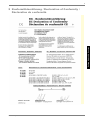
5
Anhang · Appendix · Annexes
5 Konformitätserklärung / Declaration of Conformity /
Déclaration de conformité
www.dimplex.de
A-XV
Glen Dimplex Deutschland GmbH
Geschäftsbereich Dimplex
Am Goldenen Feld 18
D-95326 Kulmbach
Irrtümer und Änderungen vorbehalten.
Subject to alterations and errors.
Sous réserve d’erreurs et modifications.
+49 (0) 9221 709 565
www.dimplex.de