1
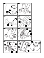
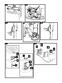
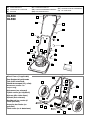
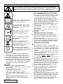
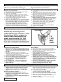
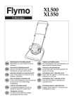
XL500
XL550
GB
IMPORTANT INFORMATION
Read before use and retain for future
reference
SE
VIKTIG INFORMATION
Läs anvisningarna före användningen och
spara dem för framtida behov
DE
WICHTIGE INFORMATION
Bitte vor dem Benutzen des Gerätes
durchlesen und gut aufbewahren
DK
VIGTIGE OPLYSNINGER
De bør læse dette før brug og gemme til
senere henvisning
FR
RENSEIGNEMENTS IMPORTANTS
A lire avant usage et à conserver pour
référence ultérieure
ES
INFORMACIÓN IMPORTANTE
Léase antes de utilizar y consérvela como
referencia en el futuro
PT
INFORMAÇÕES IMPORTANTES
Leia antes de utilizar e guarde para
consulta futura
IT
INFORMAZIONI IMPORTANTI
Leggere prima dell’uso e conservare per
consultazione futura
NL
BELANGRIJKE INFORMATIE
Leest u deze informatie voor het gebruik
en bewaar ze voor toekomstige
raadpleging
NO
VIKTIG INFORMASJON
Les bruksanvisningen før bruk og
oppbevar denne for senere bruk.
FI
TÄRKEÄÄ TIETOA
Lue tämä ennen käyttöä ja säilytä
myöhempää tarvetta varten
A
B
1
900
2
5
3
4
C
D
1
3
1
2
3
E
2
F
1
1
3
2
2
H
G
4
2
1
5
4
2
1
3
2
1
3
J
K
L
M
N
P
Q
2
1
3
5
4
4
3
9
8
2
7
1
5
6
GB - XL500/550
1. Operator Presence Control
2. Choke Control Lever
3. Upper Handle
4. Cable Tie Wrap x 2
5. Handle Knob x 2
6. Washer x 2
7. Bolt x 2
8. Lower Handle
9. Hook Assembly
10.Lower Handle Retaining Clip x2
11. Lower Handle Pin x2
12.Starting Handle
13.Fuel Tank Cap
14.Oil Filler Cap
15.Fuel Tap
16.Spark Plug Lead
17.Rating Label
18.Warning Label
19.Instruction Booklet
GB - Wheel Frame
20.Lower Handle
21.Wheels x 2
22.Upper telescopic tubes
23.Telescopic tube pin
24.Telescopic tube retaining clip
25.Lower telescopic tubes
26.Wheel retaining clips
27.Wheel frame
28.Hook Assembly
29.Lower handle bolt x 2
30.Small washer x 2
31.Lower handle pin x 2
32.Large washer x 2
33 Locknut x 2
DE - XL500/550
1. Bedienerpräsenz-Kontrollvorrichtung
2. Chokeschalthebel
3. Oberer Griff
4. Kabelhalter x 2
5. Griffknopt x 2
6. Unterlegscheibe x 2
7. Bolzen x 2
8. Unterer Griff
9. Hakeneinheit
10.Halteklammer, unterer Griff, x2
11. Stift, unterer Griff, x2
12.Starterseil
13.Tankkappe
14.Öleinfüllverschluss
15.Kraftstoffhahn
16.Zündkerzenzuleitung
17.Produkttypenschild
18.Warnetikett
19.Bedienungsanleitung
DE - Zum Radgestell gehörende Teile
20.Unterer Griff
21.Räder x 2
22.Obere Teleskoprohre
23.Teleskoprohrstift
24.Telekoprohr-Halteklammer
25.Untere Teleskoprohre
26.Radhalteklammern
27.Radgestell
28.Hakeneinheit
29.Bolzen, unterer Griff, x2
30.Kleine Unterlegscheibe x 2
31.Stift, unterer Griff, x2
32.Große Unterlegscheibe x2
33.Sicherungsmutter x2
FR - XL500/550
1. Arceau de sécurité (CPO) (Contrôle
de Présence de l’Opérateur)
2. Manette de starter
3. Poignée supérieure
4. Cable Tie Wrap x 2
5. Bouton de Guidon x 2
6. Rondelle x 2
7. Boulons x 2
8. Guidon inferieur
9. Montage du crochet
10.Attache de câble x 2
11. Boulon de poignée inférieure x 2
12.Poignée de démarrage
13.Bouchon du réservoir d’ essence
14.Bouchon de remplissage d'huile
15.Robinet à essence
16.Fil de bougie
17.Plaquette d’identification
18.Etiquette d’avertissement
19.Manuel d’instructions
FR - Chariot de transport
20.Guidon inferieur
21.Roues x 2
22.Tubes télescopiques – partie
supérieure
23.Goupille de tube télescopique
24.Clip de retenue de tube télescopique
25.Tubes télescopiques – partie
inférieure
26.Clips de retenue des roues
27.Cadre des roues
28.Montage du crochet
29.Boulon de poignée inférieure x 2
30.Petite rondelle x 2
31.Goupille de poignée inférieure x 2
32.Grosse rondelle x 2
33.Contre-écrou x 2
NL - XL500/550
1. Operator Presence Control (OPC
of Veiligheids hendel)
2. Regelhendel choke
3. Bovenste duwboom
4. Kabelklem (2 stuks)
5. Knop voor duwboom x 2
6. Ring x 2
7. Bout x 2
8. Onderstuk van duwboom
9. Haak
10.Borgclip onderste handgreep (2 stuks)
11. Bout voor onderste handgreep
(2 stuks)
12.Starthendel
13.Dop voor benzinetank
14.Oil Filler Cap
15.Fuel Tap
16.Bougiekabel
17.Productlabel
18.Waarschuwingsetiket
19.Handboek
NL - Wielframe
20.Onderstuk van duwboom
21.Wielen (2 stuks)
22.Bovenste uitschuifbare buizen
23.Pen voor uitschuifbare buis
24.Borgclip voor uitschuifbare buis
25.Onderste uitschuifbare buizen
26.Borgclips voor wielen
27.Wielframe
28.Haak
29.Bout voor onderste handgreep
(2 stuks)
30.Kleine pasring (2 stuks)
31.Pen voor onderste handgreep (2
stuks)
32.Grote pasring (2 stuks)
33 Borgmoer (2 stuks)
NO - XL500/550
1. Start/Stopp bryter
2. Chokens kontrollspak
3. Øvre håndtak
4. Kabelfeste x 2
5. Vingemutter (2 stk)
6. Skiver (2 stk)
7. Bolt (2 stk)
8. Nedre håndtak
9. Krokmontering (Hakemontering)
10.Låseklemme x 2 til nedre
håndtak
11. Bolt x 2 til nedre håndtak
12.Starthåndtak/snor
13.Bensintanklokk
14.Oljelokk
15.Bensinkran
16.Ledning/hette for tennplugg
17.Typeetiketten
18.Advarselsetikett
19.Bruksanvisning
NO - Hjulramme
20.Nedre håndtak
21.Hjul x 2
22.Øvre teleskopiske rør
23.Låsepinne til teleskopisk rør
24.Låseklemme til teleskopisk rør
25.Nedre teleskopiske rør
26.Låseklemmer til hjulene
27.Hjulramme
28.Krokmontering (Hakemontering)
29.Bolt x 2 til nedre håndtak
30.Liten skive x 2
31.Låsepinne x 2 til nedre håndtak
32.Stor skive x 2
33.Låsemutter x 2
FI - XL500/550
1. Käynnistys/pysäytys-katkaisin
2. Ryypytyksen säätövipu
3. Ylävarsi
4. Johdonpidike x 2
5. Kahvan nuppi x 2
6. Pultin välirengas x 2
7. Pultti x 2
8. Alempi kahva
9. Koukku
10.Alemman kahvan pidike x 2
11. Alemman kahvan pultti x2
12.Käynnistyskahva
13.Polttoainesäiliön korkki
14.Öljyntäyttöaukon korkki
15.Polttoainehana
16.Sytytystulpan johdin
17.Tuotteen arvokilpi
18.Varoitusnimike
19.Käyttöohjeet
FI - Pyörän runko
20.Alempi kahva
21.Pyörä x 2
22.Ylemmät teleskooppivarret
23.Teleskooppivarren sokka
24.Teleskooppivarren pidike
25.Alemmat teleskooppivarret
26.Pyörän pidikkeet
27.Pyörän runko
28.Koukku
29.Alemman kahvan pultti x 2
30.Pieni aluslaatta x 2
31.Alemman kahvan sokka x 2
32.Iso aluslaatta x 2
33 Lukkomutteri x 2
SE - XL500/550
1. Motorbromsbygel
2. Kontrollspak för choke
3. Övre handtag
4. Kabelklämma x 2
5. Knopp för hantag x 2
6. Bricka x 2
7. Bult x 2
8. Nedre handtag
9. Hakenhet
10.Fasthållningsklämma för nedre
handtag x 2
11. Bult för nedre handtag x 2
12.Starthandtag
13.Tanklock
14.Lock för oljepåfyllningshål
15.Tanklock
16.Tändkabel
17.Identifieringsetikett
18.Varningsetikett
19.IInstruktionsbok
SE - Hjulram
20.Nedre handtag
21.Hjul x 2
22.Övre teleskopiska rör
23.Sprint för teleskopiskt rör
24.Fasthållningsklämma för
teleskopiskt rör
25.Nedre teleskopiska rör
26.Fasthållningsklämmor för hjul
27.Hjulram
28.Hakenhet
29.Bult för nedre handtag x 2
30.Liten mellanläggsbricka x 2
31.Sprint för nedre handtag x 2
32.Stor mellanläggsbricka x 2
33.Låsmutter x 2
DK - XL500/550
1. Start/stopkontakt
2. Chokerbetjeningsgreb
3. Øvre håndtag
4. Kabelbåndsholder x 2
5. Håndtagsknop
6. Spændskive x 2
7. Bolt x 2
8. Nedre håndtag
9. Krogsamling
10.Clips til nederste håndtag x 2
11. Bolt til nederste håndtag x 2
12.Starthåndtag
13.Benzindæksel
14.Oliepåfyldningsdæksel
15.Brændstofhane
16.Tændrørsledning
17.Produktmærkat
18.Advarselsmœrkat
19.Brugsvejledning
DK - Hjulstel
20.Nedre håndtag
21.Hjul x 2
22.Øverste teleskoprør
23.Teleskoprørsstift
24.Teleskoprørsclips
25.Nederste teleskoprør
26.Hjulclips
27.Hjulstel
28.Krogsamling
29.Bolt til nederste håndtag x 2
30.Lille spændeskive x 2
31.Stift til nederste håndtag x 2
32.Stor spændeskive x 2
33.Låsemøtrik x 2
ES - XL500/550
1. Interruptor de contacto
2. Palanca de control del
estrangulador
3. Manillar superior
4. Sujetadores de cable x 2
5. Manija de empuñadura x 2
6. Arandela x 2
7. Perno x 2
8. Empuñadura inferior
9. Montaje del enganche
10.Clips de retención del mango
inferior x2
11. Pernos del mango inferior x2
12.Manilla de arranque
13.Tapa del tanque de combustibles
14.Tapón de llenado de aceite
15.Tapón de combustible
16.Cable de la bujía
17.Etiqueta indicadora del producto
18.Etiqueta de Advertencia
19.Manual de Instrucciones
ES - Bastidor de las ruedas
20.Empuñadura inferior
21.Ruedas x 2
22.Tubos telescópicos superiores
23.Pasador del tubo telescópico
24.Clip de retención del tubo
telescópico
25.Tubos telescópicos inferiores
26.Clips de retención de las ruedas
27.Bastidor de las ruedas
28.Montaje del enganche
29.Pernos del mango inferior x 2
30.Arandelas pequeñas x 2
31.Pasadores del mango inferior x 2
32.Arandelas grandes x 2
33 Contratuercas x 2
PT - XL500/550
1. Interruptor de Ligar/Desligar
2. Alavanca de Controlo da
Válvula de Borboleta
3. Cabo Superior
4. Braçadeira de cabo x 2
5. Maçaneta x 2
6. Arruela x 2
7. Cavilha x 2
8. Guiador inferior
9. Conjunto do Gancho
10.Clipe de retenção da pega
inferior x 2
11. Parafuso da pega inferior x 2
12.Pega de Arranque
13 Tampa do Depósito de Combustível
14.Bujão de enchimento de óleo
15.Torneira de combustível
16.Fio da vela de ignição
17.Etiqueta de Especificações do
Producto
18.Etiqueta de Aviso
19.Manual de Instruções
PT - Armação das Rodas
20.Guiador inferior
21.Rodas x 2
22.Tubos telescópicos superiores
23.Pino do tubo telescópico
24.Clipe de retenção do tubo telescópico
25.Tubos telescópicos inferiores
26.Clipes de retenção das rodas
27.Armação das rodas
28.Conjunto do Gancho
29.Parafuso da pega inferior x 2
30.Anilha pequena x 2
31.Pino da pega inferior x 2
32.Anilha grande x 2
33.Porca de aperto x 2
IT - XL500/550
1. Leva comando/controllo
2. Leva di comando starter
3. Manico superiore
4. Fascette serrafilo x 2
5. Manopola dell’impugnatura x 2
6. Rondella x 2
7. Bullone x 2
8. Impugnatura inferiore
9. Gruppo gancio
10.fermi di ritenuta impugnatura
inferiore x2
11. Bulloni impugnatura inferiore x2
12.Maniglia di avviamento
13.Tappo serbatoio carburante
14.Tappo rifornimento olio
15.Rubinetto serbatoio carburante
16.Conduttore candela
17.Etichetta con dati prodotto
18.Etichetta di pericolo
19.Manuale d’istruzioni
IT - Telaio route
20.Impugnatura inferiore
21.Ruote x 2
22.Tubi telescopici superiori
23.Spina tubo telescopico
24.Fermo di ritenuta tubo
telescopico
25.Tubi telescopici inferiori
26.Fermi di ritenuta ruote
27.Telaio ruote
28.Gruppo gancio
29.Bulloni impugnatura inferiore x 2
30.Rondelle piccole x 2
31.Spine impugnatura inferiore x 2
32.Rondelle grandi x 2
33.Controdadi x 2
GB
This product may have been purchased with a Wheel Assembly. Please
assemble your product in accordance with the relevant Instructions.
Wheel Assembly Kits are available from your local stockists.
DE
Falls dieser Rasenmäher mit einem Radgestell gekauft wurde,
müssen beim Zusammenbauen die entsprechenden Anweisungen
beachtet werden. Radgestelle sind von Ihrem Händler erhältlich.
FR
Cette tondeuse peut être équipée d'un chariot de transport.
Veuillez la monter selon les instructions appropriées. Le chariot de
transport est en vente chez votre détaillant.
NL
Het is mogelijk dat u met dit product ook een stel wielen hebt gekocht.
Zet het product volgens de van toepassing zijnde instructies in elkaar.
De wielen zijn verkrijgbaar bij uw plaatselijke wederverkoper.
NO
Det er mulig at dette produktet er kjøpt med hjulmontering.
Vennligst sett sammen produktet i henhold til relevante
anvisninger. Hjulmontering er å få hos din lokale forhandler.
FI
Tämä laite saattaa sisältää erilliset pyörät. Kokoa ohjeita
noudattaen.
Pyöriä on saatavana paikalliselta jälleenmyyjältä.
SE
Denna produkt kan ha köpts med en hjulenhet. Montera produkter
i enlighet med tillämpliga instruktioner. Hjulenheter finns att köpa
hos din lokale Flymohandlare.
DK
Dette produkt kan være købt med en hjulsamling. Saml produktet i
overensstemmelse med de relevante anvisninger. Hjulsamlinger
kan købes hos din lokale forhandler.
ES
Este producto podría haber sido comprado con un montaje de ruedas.
Monte la máquina según se indica en las instrucciones adjuntas.
Podrá obtener el montaje de ruedas de su distribuidor local.
PT
Este produto pode ter sido adquirido com um conjunto de rodas.
Monte o seu produto de acordo com as instruções pertinentes.
O conjunto de rodas existe à venda no seu retalhista local.
IT
Questo prodotto potrebbe essere stato acquistato con un gruppo
ruote. Vi preghiamo di assemblare il prodotto in base alle istruzioni
fornite. I gruppi ruote sono reperibili presso il vostro fornitore di zona.
(GB)
(DE)
(FR)
(NL)
CARTON CONTENTS
KARTONINHALT
CONTENU DU CARTON
INHOUD
(NO)
(FI)
(SE)
(DK)
XL500
XL550
KARTONGENS INNHOLD
(ES) CONTENIDO DEL CARTON
PAKETIN SISÄLTÖ
(PT) LEGENDAS DOS DESENHOS
FÖRPACKNINGENS INNEHÅLL
(IT) DE CARTONE
KARTONINDHOLD
1
3
2
4
5
6
5
6
7
4
8
10
17
9
18
16
11
10
12
11
13
19
15
14
Wheel Frame (if applicable)
20
Zum Radgestell gehörende
Teile (falls zutreffend)
22
21
Chariot de transport (s'il y a lieu)
23
Wielframe (indien van
toepassing)
23
24
Hjulramme (om relevant)
26
24
25
Pyörän runko (jos käytössä)
Hjulram (där sådan finns)
Hjulstel (hvis relevant)
26
29
30
Bastidor de las ruedas (si
fuera aplicable)
Armação das Rodas (se
aplicável)
32
31
33
31
28
32
27
Telaio ruote (se in dotazione)
30
29
21
Safety Precautions
If not used properly this lawnmower can be dangerous! This lawnmower can cause serious
injury to the operator and others, the warnings and safety instructions must be followed to
ensure reasonable safety and efficiency in using this lawnmower. The operator is responsible
for following the warning and safety instructions in this manual and on the lawnmower.
Explanation of Symbols on the XL500/XL550
Warning
Read the user instructions carefully
to make sure you understand all the
controls and what they do.
Always keep the lawnmower on the
ground when mowing. Tilting or lifting
the lawnmower may cause stones to
be thrown out
Keep bystanders away. Do not mow
whilst people especially children or
pets are in the mowing area
Beware of severing toes or hands.
Do not put hands or feet near a
rotating blade.
Disconnect the spark plug before
attempting any maintenance,
cleaning or adjustment, or if you are
going to leave the lawnmower
unattended for any period.
STOP
Blade continues to rotate after the
machine is switched off. Wait until all
machine components have completely
stopped before touching them.
General
1. Never allow children or people unfamiliar with
these instructions to use the mower. Local
regulations may restrict the age of the operator.
2. Only use the lawnmower in the manner and for
the functions described in these instructions.
3. Never operate the lawnmower when you are tired, ill
or under the influence of alcohol, drugs or medicine.
4. The operator or user is responsible for accidents
or hazards occurring to other people or their
property.
Fuel Safety
WARNING - Petrol is highly flammable
- Wear protective clothing when handling any fuels
and lubricants.
- Avoid contact with skin. If affected, wash
liberally with soap and water.
- Store fuel in a cool place in a container
specifically designed for the purpose.
- Use a fresh, clean, unleaded regular automotive
petrol
- Use 4-stroke automotive detergent oil. SAE
10W-30 is recommended for general use.
- Refuel outdoors only and do not smoke while
refuelling.
ENGLISH - 1
-
Wipe dirt and grass clippings from the fuel tank
filler cap to avoid getting dirt into the fuel tank.
- Add fuel BEFORE starting the engine. Never
remove the cap of the fuel tank or add fuel while
the engine is running or when the engine is hot.
- If petrol is spilled, do not attempt to start the
engine but move the machine away from the
area of spillage and avoid creating any source of
ignition until petrol vapours have dissipated.
- Never use stale fuel left from last season or fuel
which has been stored for long periods.
- Replace all fuel tanks and container caps securely.
- Move the product away from the fuelling area
before starting.
- Fuel should be stored in a cool place away from
naked flames.
- Your carburettor is pre-set. Normally no further
adjustment is required.
Preparation
1. While using your product always wear
substantial footwear and long trousers.
2. The use of ear protection is recommended.
3. Make sure the area to be cut is clear of sticks,
stones, bones, wire and debris; they could be
thrown by the blade.
4. Before using the machine and after any impact, check
for signs of wear or damage and repair as necessary.
5. Replace worn or damaged blades together with their
fixings in sets to preserve balance.
6. Have faulty silencers replaced.
Use
1. Do not operate the engine in a confined space
where exhaust fumes (carbon monoxide) can collect.
2. Use the mower only in daylight or good artificial light.
3. Avoid operating your mower in wet grass, where
feasible.
4. Take care in wet grass, you may lose your footing.
5. On slopes, be extra careful of your footing and
wear non-slip footwear.
6. Mowing on banks and slopes can be dangerous.
Do not mow on banks or steep slopes.
7. Do not walk backwards when mowing, you could
trip. Walk never run.
8. Never cut grass by pulling the mower towards you.
9. Release the Operator Presence control to stop
the engine before pushing the mower across
surfaces other than grass and when transporting
the lawnmower to and from the area to be mowed.
10. Never operate the lawnmower with damaged
guards or without guards in place.
11. Do not overspeed the engine or alter governor
settings. Excessive speed is dangerous and
shortens lawnmower life.
12. Keep hands and feet away from the cutting
means at all times and especially when
switching on the engine.
13. Do not tilt the mower when starting the engine, except
if the mower has to be tilted for starting. In this case,
do not tilt more than absolutely necessary and lift only
the part which is away from the operator. Always
ensure that both hands are in the operating position
before returning the appliance to the ground.
Safety Precautions
14. Never pick up or carry a lawnmower while the
engine is running
15. Spark plug lead may be hot - handle with care.
16. Do not attempt any maintenance on your
lawnmower when the engine is hot.
17. Release the Operator Presence Control, to stop
the engine, and wait until the blade has stopped:
- before leaving the mower unattended for any period.
18. Release the Operator Presence Control, to stop
the engine, wait until the blade has stopped,
disconnect the spark plug lead and wait until the
engine has cooled:- before refuelling
- before clearing a blockage;
- before checking, cleaning or working on the appliance;
- if you hit an object. Do not use your lawnmower
until you are sure that the entire lawnmower is in
a safe operating condition;
- if the lawnmower starts to vibrate abnormally. Check
immediately. Excessive vibration can cause injury.
Maintenance and storage
1. Keep all nuts, bolts and screws tight to be sure
the lawnmower is in safe working condition.
2. Replace worn or damaged parts for safety.
3. Only use the replacement blade, blade bolt,
spacer and impeller specified for this product.
4. Never store the lawnmower with fuel in the tank
inside a building where fumes can reach an
open flame or spark.
5. Allow the engine to cool before storing in any
enclosure.
6. To reduce fire hazard, keep the engine, muffler
and fuel storage area free of grass, leaves or
excessive grease.
7. If the fuel tank has to be drained, this should be
done outdoors.
8. Be careful during adjustment of the machine to
prevent entrapment of the fingers between
moving parts and fixed parts of the machine.
Assembly (without wheels)
Fitting the Lower Handle to the Lawnmower
1. Feed the hook (A2) attached to the lower handle
(A1) halfway through the centre slot of the guide
(A3), in the direction indicated by the arrow (A4).
2. Maintaining the hook (A2) in the centre slot of
the guide (A3) turn the lower handle (A1)
clockwise through 900 to place both legs of the
lower handle in position between the hood
brackets (A5).
3. Insert the pins (B1) and secure with the retaining
clips (B2).
Fitting the Upper Handle to the Lower Handle
BEFORE fitting the upper handle to the lower
handle, stabilize the lower handle by lifting the hook
(C1) to the 'parking' position (C2).
1. Ensure the Choke Control Lever is on the left
hand side when viewed from the rear.
2. Align the lower and upper handle (See fig D).
Locate the bolts (D1), washers (D2) and secure
with the handle knobs (D3).
3. Fit the cables to the handles with the cable ties
provided, making sure the cables are not
trapped between the upper and lower handles.
Assembly (with wheels)
1. Fit the lower handle (E1) to the deck with the
lower handle pin (E2) as illustrated in Fig E.
2. Attach the wheels (F1) to the wheel frame (F2) with
the wheel retaining clips (F3) as illustrated in Fig F.
3. Fit the wheel frame (G1) to the deck with the lower
handle bolt (G2), small washer (G3), large washer
(G4) and locknut (G5) as illustrated in Fig G.
4. Locate the lower telescopic tubes (H1) inside the
upper telescopic tubes (H2) and secure with the pin
(H3) and retaining clip (H4) as illustrated in Fig H.
Fit the Upper Handle to the Lower Handle by
following the instructions above in ‘Assembly
(without wheels)’ section.
Handle Position
The handle position can be adjusted using the
guide and hook assembly.
1. Lift hook (C1).
2. Position as required:
(C2)
Parking position
(C3)
Mowing position
Fuel
Use a fresh, clean, unleaded regular automotive
gasoline Do not fill the fuel tank in an enclosed area,
when the engine is hot or while you are smoking or
near a naked flame. Thoroughly clean around the fuel
tank filler cap before filling, this will help to prevent dirt
being introduced into the fuel system. Fuel should be
stored in a cool place away from naked flames. Do
not fill the tank while the engine is running. Fill the fuel
tank through a funnel fitted with a fine filter. Never fill
fuel tank completely, only fill to the base of the filler
neck. When filling the fuel tank from empty, or when
the engine has previously run dry, a minimum of 400cc
of fuel must be added (to the level of the line
indicated in the diagram) to ensure correct priming of
the fuel pump to start the engine. Your carburettor is
pre-set. Normally no further adjustment is required.
ENGLISH - 2
Oil
Use 4-stroke automotive detergent oil. SAE
10W-30 is recommended for general use.
Fill with oil as instructed in your Engine Owners
Manual provided with your product.
Starting and Stopping
To
1.
2.
3.
4.
Start your Lawnmower
Move the handle to the parking position (C2).
Connect the spark plug lead. (J).
Open the fuel tap (K).
Move the Choke control lever to the ‘Choke’
position (L) when starting from cold, and to the
‘Run’ position (N) when starting from hot.
5. Pull and firmly hold the Operator Presence
Control to the upper handle.
6. Place your right foot firmly on the deck and grasp the
top of the lower handle with your left hand. Tilt the
trimmer towards you (M). This ensures the product
is in a secure position when starting and also
prevents an unsightly ring being cut in your lawn.
7. Pull the starting handle gently until you feel a
resistance, return the starting handle slowly.
8. Pull the starting handle firmly towards you to its
full extent.
9. Allow the engine to reach its full running speed
then gently lower the lawnmower to the ground.
10. When the engine has warmed up make sure the
choke control lever is in the 'Run' (N) position.
To Stop your Lawnmower
• Blade continues to rotate after the machine has
switched off, rotating blades can cause injury.
1. Release the Operator Presence Control.
2. As the engine dies, tilt the lawnmower slightly.
This prevents a ring being cut in your lawn.
3. When the engine has stopped, lower the
lawnmower to the ground.
4. Put the handle in the Parking position (C2).
5. Close the fuel tap (K)
IMPORTANT
AIR CLEANER
Before any servicing to the
underside of your machine, close
the fuel tap, let the engine run
until it stops, disconnect the
spark plug lead and TIP THE
MACHINE ON ITS SIDE WITH
THE AIR CLEANER UPPERMOST.
TIP
THIS
WAY
ONLY
Adjusting the cutting height
Adjusting the Cutting Height
• Never use more than 2 cutting height spacers.
• Spacers can only be fitted between the blade
and the fan and never between blade and the
bolt (P).
1. Ensure the Operator Presence Control is
released, when the engine has stopped rotating
- disconnect the spark plug lead.
2. Close the fuel tap (K). Turn your lawnmower on its side.
3. Remove the blade bolt (P1) and blade (P2) as
described in ‘Removing the Blade and Fan’.
4. For a Lower Cut - Add spacers (P3) to a
maximum of 2.
5. For a Higher Cut - Take spacers (P3) away.
6. Refit the blade as described in ‘Fitting the
Blade and Fan’.
How to Mow
1. Place the handle in the mowing position (C3).
2. Mow twice a week in the growing season. Your
lawn will suffer if more than one third of its
length is cut at one time.
• Keep hands and feet away from the blade, a
rotating blade cannot be seen.
• Mowing on banks and slopes can be
dangerous. Do not mow on steep slopes.
• Always keep your feet on flat ground with the
mower below you on the slope and with the
spark plug uppermost to avoid lubricating oil
running into the cylinder.
• Do not use this mower on slopes which are
wet or more than 450 from horizontal.
• Never push the mower up the slope.
Removing & Fitting the Blade & Fan
WARNING
• Always handle the blade with care - sharp
edges could cause injury. USE GLOVES
• Spark plug lead may be hot - handle with
care.
Removing the Blade and Fan
• Renew your metal blade after 50 hours
mowing or 2 years whichever is the sooner regardless of condition.
• If the blade is cracked or damaged replace it
with a new one.
ENGLISH - 3
1. Ensure the Operator Presence Control is released,
when the engine has stopped and the blade has
stopped rotating - disconnect the spark plug lead.
2. Fully close the fuel tap (K).
3. Turn your lawnmower on its side with the air
cleaner uppermost (see pic above).
4. To remove the blade bolt (P1), hold the fan (P4)
firmly and with the spanner provided loosen the
blade bolt by turning it anti-clockwise.
5. Remove the blade bolt (P1), blade (P2), spacers
(P3) and fan (P4).
6. Inspect for damage and clean as necessary.
Removing & Fitting the Blade & Fan
Fitting the Blade and the Fan
• Before using the lawnmower, always visually
inspect to see that blades and bolts are not
worn or damaged.
• Never use more than 2 cutting height
spacers.
• Spacers can only be fitted between the blade
and the fan and never between blade and the
bolt.
1. Ensure the fan is located correctly.
2. Place the spacers (P3) onto the fan ensuring the
pegs (P5) have located into the holes (P6).
3. Place the blade (P2) onto the spacers (P3)
ensuring the pegs (P7) have located into the
holes (P8) on the blade and ensuring the blade
is positioned as illustrated in Figure P.
4. Place the blade bolt (P1) through the centre hole
(P9) of the blade.
5. Tighten down clockwise by hand.
6. Hold the fan firmly and tighten the blade bolt
with the spanner provided.
Spark Plug
An oily or carboned spark plug makes starting
difficult and decreases the efficiency of the engine.
Periodically remove the spark plug and clean and
adjust when necessary.
Gap setting 0.028 - 0.031".
Do not remove spark plug when engine is hot. Do
not sand blast the spark plug to clean it.
Cleaning the Air Filter
Q1 - Air Duct
Q2 - Air Cleaner Body
Q3 - Filter
Q4 - Latch Tabs
Q5 - Air Cleaner Cover
Never run the engine without a filter or with a dirty
filter. This will greatly reduce engine efficiency and
lead to engine damage.
Your lawnmower is fitted with an Air Cleaner, the
maintenance for which is as follows:• Check the filter before each use.
• Clean every 25 hrs or more frequently when
used in dusty areas.
• Replace filter every 200 hrs.
1. Press the latch tabs on the top of the air cleaner
cover and remove the cover.
2. Check the filter is clean and in good condition.
If the filter is dirty:Tap the air filter several times on a hard surface
to remove dirt, or blow compressed air through
the air filter from the clean side that faces the
engine. Never try to brush off dirt. Brushing will
force dirt into the fibers.
3. Wipe dirt from the air cleaner body and cover
using a moist rag. Be careful to prevent dirt
from entering the air duct that leads to the
carburetor.
4. Replace the filter and air cleaner cover.
Caring for your Lawnmower
If you do not intend to use your lawnmower for
long periods it is advisable to follow this
procedure after use:
1. Stop the engine.
2. Fully close the fuel tap. (K)
3. Restart the engine.
4. As fuel runs out the engine will begin to stop, tilt
the lawnmower slightly.
5. Once the engine has stopped, release the
Operator Presence Control.
6. Disconnect the spark plug lead.
7. Remove all fuel from the fuel tank.
Cleaning - USE GLOVES
• Keep your lawnmower clean - grass clippings
left in any of the air intakes, around the
engine or under the deck could become a
potential fire hazard.
• Do not clean with chemicals, including petrol, or
solvents - some can destroy critical plastic
parts.
1. Remove grass from under the deck with a piece
of wood or similar.
2. Using a soft brush - remove grass clippings from
around the engine and from all air intakes.
3. Remove the fan, See 'Removing and Fitting
the Blade and Fan', and clean with a soft
brush.
4. Wipe over the surface of your lawnmower with a
dry cloth.
Transporting your Lawnmower
• Turn the fuel tap to the off position and transport
with the engine in a horizontal position.
• Never transport the lawnmower when it is
running.
Storing Your Lawnmower
Turn the fuel tap to the off position and store in a
cool, dry, damp-proof and safe place with the
engine in a horizontal position. Service your
lawnmower after the last cut of the year as follows:At the end of the Mowing Season
1. Stop the engine.
2. Fully close the fuel tap. (K)
3. Restart the engine.
4. As fuel runs out the engine will begin to stop, tilt
the lawnmower slightly.
5. Once the engine has stopped, release the
Operator Presence Control.
6. Disconnect the spark plug lead.
7. Remove all fuel from the fuel tank.
8. Remove the spark plug lead and spark plug. Pour
one teaspoon (5ml) of oil through the spark plug
hole. Pull the starting handle 2 or 3 times. This will
distribute oil on the internal surfaces of the engine.
Inspect, clean and replace the spark plug. If a new
spark plug is required contact your local approved
Electrolux Outdoor Products Service Centre/Dealer.
Do not re-connect the spark plug lead.
9. Clean the air filter. See 'Cleaning the Air Filter'.
10. Renew the blade if it is cracked, damaged or
bent. Renew the blade bolt if necessary. See
'Removing and Fitting the Blade and Fan' for
complete instructions.
11. Use only genuine Flymo parts and accessories
specified for this product.
12. Clean your lawnmower thoroughly See 'Cleaning'.
13. Your local approved Electrolux Outdoor
Products Service Centre/Dealer will carry out
any service or repairs required.
14. Store your lawnmower in a cool, dry, damp-proof
and safe place.
ENGLISH - 4
Fault Finding
Engine Will Not Start
1. Ensure that the Operator Presence Control is
gripped firmly to the upper handle.
2. Check that there is sufficient fuel in the fuel tank
and the fuel tap is open
3. Check that the choke control lever is in the
correct position:- 'Run’ position (N) - for a hot
engine, 'Choke’ position (L) - for a cold engine.
4. The engine may have flooded. Remove and dry
the spark plug.
5. Petrol may be stale, replace. Once the petrol
has been replaced, it may take a little time for
fresh petrol to filter through.
6. Check that the blade bolt is tight. A loose blade
bolt could cause difficult starting.
7. If the engine will still not start - disconnect the
spark plug lead and consult you local approved
Electrolux Outdoor Products Service
Centre/Dealer.
Poor Flotation or Lack of Power
1. Disconnect the spark plug lead.
2. Clean the underside of the hood, the air filter,
the fan, around the engine and the air intakes.
3. Check that the engine choke control lever is in
the 'Run' position. (N)
4. Petrol may be stale, replace. Once the petrol
has been replaced, it may take a little time for
fresh petrol to filter through.
5. If poor flotation or lack of power persists disconnect the spark plug lead and consult your
local approved Electrolux Outdoor Products
Service Centre/Dealer.
Excessive Vibration
1. Disconnect the spark plug lead.
2. Check that the blade is correctly fitted. 'See 'Fitting
and Removing the Blade and the Fan'.
3. If the blade is damaged or worn, renew the
blade.
4. If vibration persists - do not use - disconnect the
spark plug lead and consult your local approved
Electrolux Outdoor Products Service
Centre/Dealer.
Service Recommendations
•
•
Your product is uniquely identified by a silver and black product rating label.
We strongly recommend that your product is serviced at least every twelve months, more often in
a professional application.
Guarantee and Guarantee Policy
If any part is found to be defective due to faulty
manufacture within the guarantee period, Electrolux
Outdoor Products, through its Authorised Service
Repairers will effect the repair or replacement to the
customer free of charge providing:
(a) The fault is reported directly to the Authorised Repairer.
(b) Proof of purchase is provided.
(c) The fault is not caused by misuse, neglect or
faulty adjustment by the user.
(d) The failure has not occurred through fair wear and tear.
(e) The machine has not been serviced or repaired,
taken apart or tampered with by any person not
authorised by Electrolux Outdoor Products.
(f) The machine has not been used for hire.
(g) The machine is owned by the original purchaser.
(h) The machine has not been used outside of the
country for which it was specified.
(i) The machine has not been used commercially.
* This guarantee is additional to, and in no way
diminishes the customers statutory rights.
Failures due to the following are not covered,
therefore it is important that you read the instructions
contained in this Operator's Manual and understand
how to operate and maintain your machine:
Failures not covered by guarantee
* Replacing worn or damaged blades
* Failures as a result of not reporting an initial
fault.
* Failures as a result of sudden impact.
* Failures as a result of not using the product in
accordance with the instructions and
recommendations contained in this Operator's
Manual.
* Machines used for hire are not covered by this
guarantee.
* The following items listed are considered as
wearing parts and their life is dependent on
regular maintenance and are, therefore not
normally subject to a valid warranty claim:
Blades, belts, cables, recoil ropes, filters.
* Caution!
Electrolux Outdoor Products does not accept
liability under the warranty for defects caused in
whole or part, directly or indirectly by the fitting
of replacement parts or additional parts that are
not either manufactured or approved by
Electrolux Outdoor Products, or by the machine
having been modified in any way.
Environmental Information
Electrolux Outdoor Products are manufactured
under an Environmental Management System (ISO
14001) using, where practical, components
manufactured in the most environmentally
responsible manner, according to company
procedures, and with the potential for recycling at
the end of the products’ life.
• Packaging is recyclable and plastic components
have been labelled (where practical) for
categorised recycling.
• Awareness of the environment must be
considered when disposing of ‘end-of-life’
product.
• If necessary, contact your local authority for
disposal information.
ENGLISH - 5
DISPOSAL OF FUELS AND LUBRICATING OILS
• Wear protective clothing when handling any
fuels and lubricants.
• Avoid contact with skin.
• Remove petrol and engine oil before transporting
the product.
• Contact your local authority for information of
your nearest Recycling/Disposal Station.
• Do NOT dispose of used fuels/oils with
household waste
• Do NOT dispose of used fuels/oils to water.
• Waste fuels/oils are harmful, but can be
recycled and should be disposed of through
the recognised facilities.
• Do NOT incinerate
DECLARATION OF CONFORMITY
KONFORMITÄTSERKLÄRUNG
I, the undersigned M. Bowden of Electrolux
Outdoor Products, Aycliffe Industrial Park,
NEWTON AYCLIFFE, Co. Durham. DL5
6UP. Certify that the Lawnmower:Category........ Petrol Hover
Make.............. Electrolux Outdoor
Products
Conforms to the specifications of Directive
2000/14/EEC
I, the undersigned M. Bowden of Electrolux
Outdoor Products, Aycliffe Industrial Park,
NEWTON AYCLIFFE, Co. Durham. DL5
6UP Certify that a sample of the above
product has been tested using directive
81/1051/EEC as a guide. The maximum Aweighted sound pressure level recorded at
operator position under free field semi
anechoic chamber conditions was :-
Type of Cutting Device... Rotary Blade
Identification of Series.....See Product Rating Label
Conformity Assesment Procedure....ANNEX VI
Notified Body....................I.T.S., Cleeve Road, Leatherhead,
Surrey. KT22 7SB England
Other Directives:-.............98/37/EEC, 89/336/EEC,
& applicable standards:-.EN836:1997, EN ISO14982:1998
Ich, der Unterzeichner M. Bowden of
Electrolux Outdoor Products, Aycliffe
Industrial Park, NEWTON AYCLIFFE, Co.
Durham. DL5 6UP. bescheinige hiermit,
dass der Rasenmäher:Kategorie.... Benzinluftkissenmäher
Fabrikat....... Electrolux Outdoor Products
die Spezifikationen der Direktive
2000/14/EG erfüllt
Ik, ondergetekende M. Bowden of Electrolux
Outdoor Products, Aycliffe Industrial Park,
NEWTON AYCLIFFE, Co. Durham. DL5
6UP. verklaar dat de grasmaaimachine:Categorie.... Benzine zweefmaaie
Merk............ Electrolux Outdoor Products
Voldoet aan de specificaties van directief
2000/14/EEC
Ich, der Unterzeichner M. Bowden, Electrolux
Outdoor Products, Aycliffe Industrial Park,
NEWTON AYCLIFFE, Co. Durham, DL5 6UP,
bescheinige hiermit, daß eine Probe des obigen
Produkts getestet wurde und dabei ISO 5349 als
Richtschnur verwendet wurde. Der maximale
gewichtete Vibrationseffektivwert, der an der
Handposition des Bedieners gemessen wurde,
betrug:-
Je soussigné M. Bowden, Electrolux Outdoor
Products, Aycliffe Industrial Park, NEWTON
AYCLIFFE, Co. Durham, DL5 6UP, GrandeBretagne, certifie qu’un échantillon du produit
ci-dessus a été essayé selon les indications
de la norme ISO 5349. La moyenne
quadratique pondérée des vibrations
enregistrées à la position de la main de
l’opérateur était de:-
Type........................................................................... A
Fabricant du moteur.................................................. B
Largeur de coupe...................................................... C
Vitesse de rotation de l'outil de coupe...................... D
Niveau garanti de puissance sonore......................... E
Niveau mesuré de puissance sonore........................ F
Niveau....................................................................... G
Valeur.........................................................................H
Poids......................................................................... J
Ik, ondergetekende M. Bowden, Electrolux
Outdoor Products, Aycliffe Industrial Park,
NEWTON AYCLIFFE, Co. Durham, DL5 6UP,
verklaar hierbij dat een proefexemplaar van het
bovengenoemde product is getest volgens richtlijn
81/1051/EEC. Het maximale A-belaste
geluidsdrukniveau dat is geregistreerd bij de positie
van de bediener in een semi geluiddichte ruimte bij
vrije veld condities bedraagt:-
Type maaier.................................. Roterend mes
Identificatie van serie.................... Zie Productlabel
Procedure voor het beoordelen van conformiteit..........ANNEX VI
Op de hoogte gestelde instantie.I.T.S., Cleeve Road, Leatherhead,
Surrey. KT22 7SB England
Andere directieven........................98/37/EEC, 89/336/EEC
en aan de volgende normen.......EN836:1997, EN ISO14982:1998
A
B
C
D
E
F
G
H
J
Typ................................................................................ A
Motorhersteller.............................................................. B
Schnittbreite.................................................................. C
Umdrehungsgeschwindigkeit des Schneidwerks......... D
Garantierter Geräuschpegel..........................................E
Gemessener Geräuschpegel........................................ F
Höhe ............................................................................ G
Wert...............................................................................H
Gewicht......................................................................... J
Je soussigné M. Bowden, Electrolux Outdoor
Products, Aycliffe Industrial Park, NEWTON
AYCLIFFE, Co. Durham, DL5 6UP, GrandeBretagne, certifie qu’un échantillon du produit cidessus a été essayé selon les indications de la
directive 81/1051/EEC. Le niveau maximum
pondéré de pression acoustique enregistré à la
position de l’opérateur en champ libre en
chambre demi-sourde était de:-
Type d'outil de coupe...............Lame rotative
Identification de la serie........... Voir la Plaquette D’identification
Procédure d'évaluation de la conformité........ANNEX VI
Organisme notifié..................... I.T.S., Cleeve Road, Leatherhead,
Surrey. KT22 7SB England
Autres directives....................... 98/37/EEC, 89/336/EEC
et aux normes...........................EN836:1997, EN ISO14982:1998
I, the undersigned M. Bowden of Electrolux
Outdoor Products, Aycliffe Industrial Park,
NEWTON AYCLIFFE, Co. Durham. DL5
6UP Certify that a sample of the above
product has been tested using ISO 5349 as
a guide. The maximum weighted root mean
square value of vibration recorded at
operator’s hand position was:-
Type............................................................................
Engine Manufacturer...................................................
Width of Cut................................................................
Speed of Rotation of Cutting Device..........................
Guaranteed sound power level...................................
Measured Sound Power Level....................................
Level............................................................................
Value...........................................................................
Weight.........................................................................
Ich, der Unterzeichner M. Bowden, Electrolux
Outdoor Products, Aycliffe Industrial Park,
NEWTON AYCLIFFE, Co. Durham, DL5 6UP,
bescheinige hiermit, daß eine Probe des obigen
Produkts getestet wurde und dabei Direktive
81/1051/EWG als Richtschnur verwendet wurde.
Der maximale A-gewichtete Schalldruckpegel, der
an der Bedienerposition unter FreifeldHalbschalltot-Kammerbedingungen gemessen
wurde, betrug:-
Schneidwerktyp................................. Rotierendes Messer
Identifizierung der reihe..................... Siehe Produkttypenschild
Konformitätsbestätigungsverfahren.ANNEX VI
Benachrichtigte Behörde.................. I.T.S., Cleeve Road, Leatherhead,
Surrey. KT22 7SB England
Andere Direktiven-............................. 98/37/EEC, 89/336/EEC,
und Normen:-.....................................EN836:1997, EN ISO14982:1998
Je soussigné M. Bowden of Electrolux
Outdoor Products, Aycliffe Industrial Park,
NEWTON AYCLIFFE, Co. Durham. DL5
6UP. certifie que la tondeuse:Catégorie..... Coussin d’air à essence
Marque........ Electrolux Outdoor Products
est conforme aux spécifications de la
Directive 2000/14/EEC
DÉCLARATION DE CONFORMITÉ
CONFORMITEITSVERKLARING
Ik, ondergetekende M. Bowden, Electrolux
Outdoor Products, Aycliffe Industrial Park,
NEWTON AYCLIFFE, Co. Durham, DL5 6UP,
verklaar hierbij dat een proefexemplaar van het
bovengenoemde product is getest volgens ISO
5349 als richtlijn. De maximale belaste
effectieve waarde van trilling, geregistreerd bij
de positie van de hand van de bediener,
bedraagt:-
Type.......................................................................... A
Fabrikant van motor.................................................. B
Maaibreedte.............................................................. C
Toerental maaier....................................................... D
Gegarandeerd geluidsvermogen...............................E
Gemeten geluidsvermogen....................................... F
Niveau....................................................................... G
Waarde...................................................................... H
Gewicht..................................................................... J
DECLARACIÓN DE CONFORMIDAD
DECLARAÇÃO DE CONFORMIDADE
El abajo firmante M. Bowden of Electrolux
Outdoor Products, Aycliffe Industrial Park,
NEWTON AYCLIFFE, Co. Durham. DL5 6UP.
Certifica que el cortacésped:Categoría.... Cortacésped aerodeslizador
de gasolina
Marca......... Electrolux Outdoor Products
Está conforme con las especificaciones de
la Directiva 2000/14/EEC
El abajo firmante M. Bowden, Electrolux Outdoor
Products, Aycliffe Industrial Park, NEWTON
AYCLIFFE, Co. Durham DL5 6UP. Certifico que ha
sido probada una muestra del producto
anteriormente mencionado utilizando la directiva
81/1051/EEC como guía. El máximo nivel de
presión de sonido ponderado A registrado en la
posición del operario bajo condiciones de cámara
anecóica de semi campo fue de:-
Tipo de dispositivo de corte... Cuchilla rotativa
Identificación de la serie.......... Ver Etiqueta de Identificación Del
Producto
Procedimiento de evaluación de conformidad....ANNEX VI
Organismo notificado........... I.T.S., Cleeve Road, Leatherhead,
Surrey. KT22 7SB England
Otras directivas..........98/37/EEC, 89/336/EEC
y con las normativas.EN836:1997, EN ISO14982:1998
Eu, abaixo assinado, M. Bowden of Electrolux
Outdoor Products, Aycliffe Industrial Park,
NEWTON AYCLIFFE, Co. Durham. DL5 6UP.
Certifico que a Máquina de Cortar Relva:Categoria... Máquina de Cortar Relva a
Gasolina, com Almofada de Ar
Marca....... Electrolux Outdoor Products
Está em conformidade com a Directiva
2000/14/CEE
A
XL500/XL550
B
Honda GCV135/GCV160
C
50.5 cm
D
3,300 RPM
E
99 dB (A)
F
97.0 dB (A)
G
86.8 dB(A)
H
3.3 m/s2
J
16 kg/16.5 kg
A
B
C
D
E
F
G
H
J
Eu, abaixo assinado, M. Bowden, Electrolux
Outdoor Products, Aycliffe Industrial Park,
NEWTON AYCLIFFE, Co. Durham, DL5
6UP, Certifico que uma amostra do produto
acima foi testada tendo como guia a norma
ISO 5349. O valor máximo da média
quadrática pesada da vibração registado na
posição da mão do operador foi:-
Tipo ........................................................................... A
Fabricante do Motor................................................... B
Largura de Corte........................................................ C
Velocidade de Rotação do Dispositivo de Corte........ D
Nível de Intensidade de Som Garantido.................... E
Nível de Intensidade de Som Medido........................ F
Nível............................................................................ G
Valor............................................................................ H
Peso............................................................................ J
Il sottoscritto, M. Bowden, Electrolux Outdoor
Products, Aycliffe Industrial Park, NEWTON
AYCLIFFE, Co. Durham, DL5 6UP, dichiara che
un campione del suddetto prodotto è stato testato
in base alla direttiva 81/1051/CEE. Il livello
massimo di pressione sonora categoria A rilevato
in corrispondenza della posizione di guida in
condizioni di camera semianecoica in campo
libero era di:-
Tipo di lama.................. Rotativa
Identificazione serie..... Vedi Etichetta Dati Prodotto
Procedura di valutazione della conformità....................ANNEX VI
Ente notificato...............I.T.S., Cleeve Road, Leatherhead,
Surrey. KT22 7SB England
Altre direttive.................98/37/EEC, 89/336/EEC
e alle normative............EN836:1997, EN ISO14982:1998
El abajo firmante M. Bowden, Electrolux
Outdoor Products, Aycliffe Industrial Park,
NEWTON AYCLIFFE, Co. Durham DL5 6UP.
Certifico que ha sido probada una muestra del
producto anteriormente mencionado utilizando
como guía ISO 5349. El valor máximo
ponderado de la media de la raíz cuadrada de
la vibración registrada en la posición de la
mano del operario fue de-
Tipo.......................................................................
Fabricante del motor.............................................
Anchura de corte...................................................
Velocidad de rotación del dispositivo de corte......
Nivel de potencia sonora garantizado...................
Nivel de potencia sonora medido..........................
Nivel......................................................................
Valor......................................................................
Peso......................................................................
Eu, abaixo assinado, M. Bowden, Electrolux
Outdoor Products, Aycliffe Industrial Park,
NEWTON AYCLIFFE, Co. Durham, DL5 6UP,
Certifico que uma amostra do produto acima foi
testada tendo como guia a directiva 81/1051/CEE.
O valor máximo da média pesada A do nível de
pressão do som registado na posição do
operador, em condições de câmara semianecóica de campo livre foi:-
Tipo de Dispositivo de Corte..Lâmina Rotativa
Identificação da série............... Consulte a Etiqueta de
Especificações do Produto
Procedimento de Avaliação de Conformidade.....ANNEX VI
Órgão Notificado......................I.T.S., Cleeve Road, Leatherhead,
Surrey. KT22 7SB England
Outras Directivas.......98/37/EEC, 89/336/EEC
e com as normas...... EN836:1997, EN ISO14982:1998
Il sottoscritto M. Bowden of Electrolux
Outdoor Products, Aycliffe Industrial Park,
NEWTON AYCLIFFE, Co. Durham. DL5
6UP. dichiara che il tagliaerba:Categoria.... Tosaerba aeroscivolante a
benzina
Marca......... Electrolux Outdoor Products
è conforme alle normative della Direttiva
2000/14/CEE
DICHIARAZIONE DI CONFORMITÀ
Il sottoscritto, M. Bowden, Electrolux
Outdoor Products, Aycliffe Industrial Park,
NEWTON AYCLIFFE, Co. Durham, DL5
6UP, dichiara che un campione del suddetto
prodotto è stato testato in base alla direttiva
ISO 5349. Il valore ponderale massimo di
vibrazione sonora efficace rilevato in
corrispondenza delle mani dell’operatore
era di:-
Tipo.......................................................................
Marca motore........................................................
Larghezza di taglio................................................
Velocità di rotazione della lama............................
Livello sonoro garantito.........................................
Livello sonoro misurato.........................................
Livello....................................................................
Valore....................................................................
Peso......................................................................
A
B
C
D
E
F
G
H
J
Newton Aycliffe, 2002
M. Bowden,
Research & Development Director
BELGIQUE/BELGIË
Flymo Belgique/België
Tel: 02 363 0311, Fax: 02 363 0391
ČESKÁ REPUBLIKA
Electrolux, spol. s.r.o., oz Electrolux Outdoor Products,
Na Křečku 365, Praha 10 - Horní Měcholupy.
Tel: 02/7847 0164, Info-linka: 0800/110 220
Internet: www.partner-flymo.cz E-mail: [email protected]
DANMARK
Electrolux Outdoor Products, Flymo/Partner A/S,
Lundtoftegaardsvej 93A, DK 2800 Kgs.Lyngby
Tel: 45 87 75 77, Fax: 45 93 33 08, www.flymo-partner.dk
DEUTSCHLAND
Flymo Deutschland
Tel: 097 21 7640, Fax:097 21 764202
ESTONIA
Electrolux Estonia Ltd (Electrolux Eesti AS)
Tel: (372) 6650010
FRANCE
Flymo France SNC
Tel 01 46 67 8141, Fax 01 43 34 2491
FINLAND SUOMI
Electrolux Outdoor Products Finland
Tel: 00 358 9 39611, Fax: 00 358 9 3961 2644
ITALIA
McCulloch Italiana s.r.l. - Via Como 72, 23868 Valmadrera
(LECCO) - ITALIA
Tel: 800 017829, Fax: 0341 581671
IRELAND
Flymo Ireland
Tel: 01 4565222, Fax: 01 4568551
MAGYARORSZÁG
Electrolux Lehel Kft
Tel: 00 36 1 251 41 47
NORGE
Flymo/Partner, div. av Electrolux Motor a.s.
Tel: 69 10 47 90
NEDERLAND
Flymo Nederland
Tel: 0172-468322, Fax: 0172-468219
ÖSTERREICH
Husqvarna-Ges.m.b.H. Nfg. KG, Industriezeile 36, 4010 LINZ,
Tel: 0732 770101-0, Fax: 0732 770101-40,
email: [email protected] Internet: www.husqvarna.at
POLSKA
Electrolux Poland Sp. z.o.o. Husqvarna, 01-612 Warszawa
Myslowicka 10/2
Tel:- (22) 8332949
SLOVENIJA
Husqvarna-Ges.m.b.H. Nfg. KG, Industriezeile 36, 4010 LINZ,
Tel: 0732 770101-0, Fax: 0732 770101-40,
email: [email protected] Internet: www.husqvarna.at
SLOVENSKA
Electrolux Slovakia s.r.o., Borova Sihot 211, 033 01 Lipt. Hradok
Tel: 044 522 14 19, Fax: 044 522 14 18, www.flymo-partner.sk
SCHWEIZ/SUISSE/SUIZZERA
Flymo Schweiz/Suisse/Suizzera
Tel 062 889 93 50 / 889 94 25, Fax 062 889 93 60 / 889 94 35
SVERIGE
Electrolux Outdoor Products, Sverige
Tel: 036 – 14 67 00, Fax: 036 – 14 60 70
UNITED KINGDOM
Electrolux Outdoor Products United Kingdom
Tel: 01325 300303, Fax: 01325 310339
Electrolux Outdoor Products
Aycliffe Industrial Park
NEWTON AYCLIFFE
Co.Durham DL5 6UP
ENGLAND
Telephone - (00) 44 1325 300303 Fax - (00) 44 1325 310339
UK Telephone - 01325 300303 Fax - 01325 310339
Our policy of continuous improvement means that the specification of products may be altered from time to time without prior notice.
Electrolux Outdoor Products manufacture products for a number of well known brands under various registered patents, designs and
trademarks in several countries.
© Electrolux Outdoor Products Ltd. Registered Office, Electrolux Works, Oakley Road, Luton LU4 9QQ
Registered number 974979 England
The Electrolux Group. The world’s No.1 choice.
The Electrolux Group is the world’s largest producer of powered appliances for kitchen, cleaning and outdoor use. More than 55
million Electrolux Group products (such as refrigerators, cookers, washing machines, vacuum cleaners, chain saws and lawn
mowers) are sold each year to a value of approx. USD 14 billion in more than 150 countries around the world.
5119369-02