1
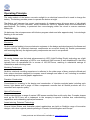
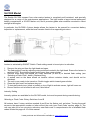
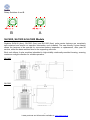
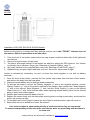
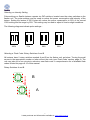
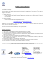
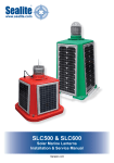
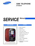
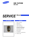
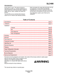
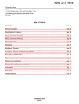
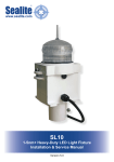
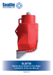
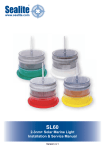
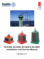
ISO9001:2000
Lic 14834
SAI Global Ltd
SLC300, SLC400, SLC500 & SLC600
Installation and Service Manual
Version 3.1
Table of Contents
Introduction
2
Operating Principle
3
Technology
3
SLC300
4
SLC400, SLC500 & SLC600
Maintenance & Servicing
5
Flash Codes
9
Troubleshooting
15
Sealite Lantern Warranty
16
8
Introduction
Congratulations! By choosing to purchase a Sealite lantern you have become the owner of one of the
most advanced LED marine lanterns in the world.
Sealite Pty Ltd has been manufacturing lanterns for over 20 years, and particular care has been
taken to ensure your lantern gives years of service.
As a commitment to producing the highest quality products for our customers, Sealite has been
independently certified as complying with the requirements of ISO 9001:2000 quality management
system.
Sealite lanterns comply with requirements of the US Coast Guard in 33 CFR part 66 for Private Aids
To Navigation.
By taking a few moments to browse through this booklet, you will become familiar with the versatility
of your lantern, and be able to maximise its operating function.
Please remember to complete the Sealite warranty registration card accompanying your lantern.
2
Latest products and information available at www.sealite.com.au
Operating Principle
The solar module of the lantern converts sunlight to an electrical current that is used to charge the
battery. The battery provides power to operate the lantern at night.
The flasher unit has very low current requirements. A microprocessor drives an array of ultra bright
LED’s through a DC/DC converter, which enables the LED’s to operate within the manufacturer’s
specifications. The battery is protected from over-charging within the circuit to ensure maximum
battery life.
On darkness, the microprocessor will initiate a program check and after approximately 1 minute begin
flashing to the set code.
Technology
Electronics
Sealite employs leading in-house electronic engineers in the design and development of software and
related circuitry. All individual electronic components are sourced directly by Sealite procurement
staff ensuring that only the highest quality components are used in our products.
LED Technology
All marine lanterns use the latest advancements in LED (Light Emitting Diode) technology as a light
source. The major advantage of LED’s over traditional light sources is well established in that they
typically have an operational life in excess of 100,000 hours, resulting in substantial savings to
maintenance and servicing costs.
Moulding Techniques
Sealite’s rotational moulding experience is reflected in the wide range of buoy products offered and
their unique structures designed to increase overall strength and ease of use, including in-moulded
cross bracing and in-mould graphic applications.
Precision Construction
Commitment to investing in the design and construction of injection-moulded parts including optic
lenses, light bases and a range of other components ensures that all Sealite products are of a
consistent and superior quality.
Optical Performance
Sealite manufactures a range of marine LED lenses moulded from multi-cavity dies. Complex shapes
such as the SL70 lens are a testament to the company’s superior in-house lens manufacturing
capabilities and outstanding optical performance.
Award-winning, Patented Technology
Several United States and Australian patent registrations are held on Sealite’s range of innovative
designs, with other regional patents pending in Canada, United Kingdom and Europe.
3
Latest products and information available at www.sealite.com.au
SLC300 Model
The Sealite SLC300 compact 3nm solar marine lantern is completely self-contained, and specially
designed for a range of low maintenance applications. The light boasts a large internal waterproof
battery compartment, a 20 LED flasher unit, and 4 premium-grade solar modules mounted to collect
sunlight at all angles.
In particular, the SLC300’s 2-piece design allows the lantern to be opened for convenient battery
inspection or replacement, while the base remains fixed to the supporting structure.
Installation of SLC300 Model
Lantern is activated by ON/OFF Switch. Flash setting needs to be set prior to activation.
1. Remove the wing nut from the light head and open.
2. The flash setting is set by adjusting rotary switches located in the light head. Ensure the lantern is
switched ‘OFF’ by switching toggle switch away from green sticker.
3. Remove white bung and adjust the rotary switches (A and B) to desired flash setting (see
‘Selecting a Flash Code’, below). Replace bung.
4. A sealed vent on the base allows air transfer without moisture intake, and should not be
disturbed.
5. The unit is now ready to be turned on. Switch toggle switch toward green sticker.
6. Close the light head, and replace wing nut.
7. To test place dark cover (towel or jacket) on top of light to activate sensor, light will come on.
8. Ensure that the unit is bolted to an even, flat surface.
Intensity Setting
Intensity options are available for the SLC300 model, but must be preset during manufacturing.
Selecting a Flash Code- Rotary Switches A and B
All lanterns have 2 rotary switches marked A and B on the flasher unit, as below. Turning the small
arrows to the appropriate number or letter will set the code (see ‘Flash Code’ section, page 9). The
unit may take up to one minute to activate a new flash code. A comprehensive list of available flash
codes is listed on pages 9-15 of this manual.
4
Latest products and information available at www.sealite.com.au
Rotary Switches A and B
B
A
SLC400, SLC500 & SLC600 Models
Sealite’s SLC400 (4nm), SLC500 (5nm) and SLC600 (6nm) solar marine lanterns are completely
self-contained and require no operator intervention once installed. The user-friendly 2-piece design
allows the lanterns to be opened for convenient battery inspection or replacement, after years of
service, whilst the base remains fixed to the supporting structure.
Each unit utilises 4 solar modules imbedded in high-visibility rotationally-moulded housing, ensuring
maximum sunlight collection for reliable operation.
SLC400
SLC500
5
Latest products and information available at www.sealite.com.au
SLC600
Installation of SLC400, SLC500 & SLC600 Models
Before turning light on, intensity and flash settings must be set. Label “FRONT” indicates front of
the lantern, where all operations must take place.
1. From the front of the lantern unscrew the four cap screws located at either side of the light-head
and remove.
2. Remove bung from base of light-head.
3. The power and range settings of the lantern are adjust by setting the DIP switches. Your lantern
is normally set to maximum range (see ‘Selecting an Intensity Setting’, page 7).
4. Set rotary switches to the required flash code (see ‘Selecting a Flash Code’, page 7).
5. Replace bung, and place light-head back onto unit. Screw four cap screws up tight.
Lantern is activated by connecting +ve and -ve wires from solar regulator to +ve and -ve battery
terminals.
1. From the front of the lantern, unscrew the four socket cap screws from the base of the lantern,
and remove the body from the base plate.
2. Unscrew internal battery box lid with pan-head screwdriver.
3. To activate the lantern, connect the “Battery Negative (-)” wire to the negative terminal, and the
“Battery Positive (+)” wire to the positive terminal of the battery. Next connect the “Solar Negative
(-)” wire to the internal “Solar Negative (-)” wire, and the “Solar Positive (+) wire to the internal
“Solar Positive (+)” wire. Care must be taken when replacing internal battery lid to ensure internal
wiring is clear from sealed gasket.
4. Replace pan-head screws with battery box lid.
5. Replace the lantern body onto the base plate ensuring that no wiring is protruding, and screw four
socket cap screws up tight.
6. To test place dark cover (towel or jacket) on top of light to activate sensor, light will come on.
7. Ensure that the unit is bolted to an even, flat surface.
Care must be taken to observe the polarity of each wire before they are connected.
To ensure waterproofing of the unit, make sure that no wires are protruding and that there is
an even seal.
6
Latest products and information available at www.sealite.com.au
Selecting an Intensity Setting
Pulse settings on Sealite lanterns operate via DIP switches, located near the rotary switches on the
flasher unit. The pulse settings may be used to reduce the power consumption and intensity of the
lantern. Setting the lantern to 25% pulse will reduce the power consumption to 25% of the normal
100% setting and the range by 50%. This setting may be used to adjust to local sunlight conditions.
The following diagrams indicate pulse settings:-
O
N
O
N
O
N
O
N
1
2
1
2
1
2
1
2
100%
75%
50%
25%
Selecting a Flash Code- Rotary Switches A and B
All lanterns have 2 rotary switches marked A and B on the flasher unit, as below. Turning the small
arrows to the appropriate number or letter will set the code (see ‘Flash Code’ section, page 9). The
unit may take up to one minute to activate a new flash code. A comprehensive list of available flash
codes is listed on pages 9-15 of this manual.
Rotary Switches A and B
B
A
7
Latest products and information available at www.sealite.com.au
Maintenance and Servicing
Designed to be almost maintenance-free, the SLC300, SLC400, SLC500 & SLC600 require minimal
attention, though the following maintenance and servicing information is provided to help ensure the
life of your Sealite product.
1. Cleaning Solar Panels- occasional cleaning of the solar panels may be required. Using a cloth
and warm soapy water, wipe off any foreign matter before rinsing the panels with fresh water.
2. Battery Check- inspection of batteries should be performed every three years (minimum) to
ensure that the charger, battery and ancillary electronics are functioning correctly. Using a
voltage meter, check that the battery voltage is at least 12 volts under 100MA load, and ensure
all terminals are clear of foreign matter.
Replacing the battery
The SLC300, SLC400, SLC500 & SLC600 lanterns have a sealed battery compartment which
provides the user with the ability to change the battery after years of operation. The 2-piece design
ensures ease of maintenance, as the base remains fixed to the supporting structure.
1. From the front of the lantern, unscrew the four socket cap screws from the base of the lantern,
and remove the body from the base plate (for SLC300’s- carefully lower body until chain takes
weight).
2. Unscrew the 4 pan-head screws from the battery lid to gain access to battery.
3. Disconnect the positive and negative wires from the battery.
4. Discard old battery in a safe manner.
5. Reattach positive and negative wires to the new battery.
6. Replace the 4 pan-head screws with the battery lid.
7. Replace the lantern body onto the base plate ensuring that no wiring is protruding, and screw four
socket cap screws firmly.
8. To test place dark cover on top of light to activate sensor, light will come on.
Care must be taken to observe the polarity of each wire before they are connected.
To ensure waterproofing of the unit, make sure that no wires are protruding and that there is
an even seal.
Always discard old batteries in a safe manner.
8
Latest products and information available at www.sealite.com.au
Flash Codes
SEALITE® code reference is listed by number of flashes
For the latest version of this document, check:
http://www.sealite.com.au
E-mail: [email protected]
Symbols
FL
F
Q
VQ
OC
ISO
LFL
MO
Flash followed by number Eg. FL 1 S, one flash every second
Fixed
Quick flash
Very quick flash
Occulting; greater period on than off
Isophase; equal period on and off
Long flash long
Morse code ( ) contains letter
For example, VQ (6) + LFL 10 S means 6 very quick flashes followed by a long flash, during a 10second interval.
The amount of power your lantern draws through the night depends on the duty cycle, i.e. the amount
of time on as a proportion to the timing cycle. For example, 0.5 seconds on and 4.5 seconds off
equals a 10% duty cycle.
It is best to operate at the lowest duty cycle appropriate to the actual needs of the application.
Please note, Sealite models will retain full autonomy in normal operating conditions with duty-cycles
up to approximately 30%. In applications whereby duty cycles exceed this limit, a reduction in lantern
intensity is recommended. Please contact a Sealite consultant if assistance is required.
Recommended Rhythm for Flashing Light - IALA Regions A and B
MARK DESCRIPTION
RHYTHM
Port Hand & Starboard Marks:
Any, other than Composite Group Flashing (2+1)
Preferred Channel Starboard:
Composite Group Flashing (2+1)
Preferred Channel Port:
Composite Group Flashing (2+1)
North Cardinal Mark:
Very quick or quick
East Cardinal Mark:
Very quick (3) every 5 seconds or quick (3) every 10 seconds
South Cardinal Mark:
Very quick (6) + long flash every 10 seconds or quick (6) + long flash every 15 seconds
West Cardinal Mark:
Very quick (9) every 10 seconds or quick (9) every 15 seconds
Isolated Danger Mark:
Group flashing (2)
Safe Water Mark:
Isophase, occulting, one long flash every 10 seconds or Morse Code “A”
Special Marks:
Any, other than those described for Cardinal, Isolated Danger or Safe Water Marks
9
Latest products and information available at www.sealite.com.au
SWITCH
A
B
0
0
D
3
E
3
F
3
7
3
8
3
9
3
A
3
8
4
B
3
9
4
C
3
F
4
1
0
0
5
0
4
2
0
3
0
4
0
5
0
6
0
7
0
1
2
8
0
9
0
D
6
1
5
A
0
2
5
B
0
3
5
C
0
D
0
2
2
5
4
E
2
4
6
4
5
5
5
E
0
F
0
6
5
0
1
1
1
2
1
3
2
3
6
F
2
3
1
8
5
4
1
5
1
9
5
6
1
7
1
4
2
8
2
0
3
FLASH CODE
ON
OFF
F (Steady light)
VQ 0.5 S
VQ 0.6 S
VQ 0.6 S
Q1S
Q1S
Q1S
Q1S
Q1S
Q 1.2 S
Q 1.2 S
Q 1.2 S
FL 1.5 S
FL 1.5 S
FL 1.5 S
FL 1.5 S
FL 2 S
FL 2 S
FL 2 S
FL 2 S
FL 2 S
FL 2 S
ISO 2 S
FL 2.5 S
FL 2.5 S
FL 2.5 S
FL 3 S
FL 3 S
FL 3 S
FL 3 S
FL 3 S
FL 3 S
FL 3 S
ISO 3 S
OC 3 S
OC 3 S
OC 3.5 S
FL 4 S
FL 4 S
FL 4 S
FL 4 S
FL 4 S
FL 4 S
FL 4 S
FL 4 S
ISO 4 S
OC 4 S
OC 4 S
FL 4.3 S
FL 5 S
FL 5 S
FL 5 S
FL 5 S
FL 5 S
FL 5 S
ISO 5 S
LFL 5 S
OC 5 S
0.2
0.2
0.3
0.2
0.3
0.4
0.5
0.8
0.3
0.5
0.6
0.2
0.3
0.4
0.5
0.2
0.3
0.4
0.5
0.7
0.8
1.0
0.3
0.5
1.0
0.2
0.3
0.4
0.5
0.6
0.7
1.0
1.5
2.0
2.5
2.5
0.2
0.3
0.4
0.5
0.6
0.8
1.0
1.5
2.0
2.5
3.0
1.3
0.2
0.3
0.5
0.9
1.0
1.5
2.5
2.0
3.0
0.3
0.4
0.3
0.8
0.7
0.6
0.5
0.2
0.9
0.7
0.6
1.3
1.2
1.1
1.0
1.8
1.7
1.6
1.5
1.3
1.2
1.0
2.2
2.0
1.5
2.8
2.7
2.6
2.5
2.4
2.3
2.0
1.5
1.0
0.5
1.0
3.8
3.7
3.6
3.5
3.4
3.2
3.0
2.5
2.0
1.5
1.0
3.0
4.8
4.7
4.5
4.1
4.0
3.5
2.5
3.0
2.0
10
Latest products and information available at www.sealite.com.au
SWITCH
A
B
1
3
2
3
C
6
B
5
C
5
8
1
9
1
A
1
7
5
B
1
5
2
9
2
6
4
3
3
4
3
A
4
9
6
5
6
D
5
C
1
E
5
B
4
6
2
A
2
6
6
B
2
F
5
C
4
7
6
0
6
1
6
D
1
2
6
E
1
1
4
C
2
D
2
7
2
2
4
8
6
5
3
6
3
F
1
D
4
3
4
0
2
4
4
7
4
A
6
E
4
FLASH CODE
ON
OFF
OC 5 S
OC 5 S
FL 6 S
FL 6 S
FL 6 S
FL 6 S
FL 6 S
FL 6 S
FL 6 S
FL 6 S
ISO 6 S
LFL 6 S
OC 6 S
OC 6 S
OC 6 S
FL 7 S
FL 7 S
OC 7 S
FL 7.5 S
FL 7.5 S
FL 8 S
FL 8 S
ISO 8 S
LFL 8 S
OC 8 S
LFL 8 S
FL 9 S
FL 9 S
OC 9 S
FL 10 S
FL 10 S
FL 10 S
FL 10 S
FL 10 S
FL 10 S
LFL 10 S
LFL 10 S
ISO 10 S
LFL 10 S
OC 10 S
OC 10 S
OC 10 S
FL 12 S
FL 12 S
LFL 12 S
FL 15 S
LFL 15 S
OC 15 S
LFL 20 S
FL 26 S
4.0
4.5
0.2
0.3
0.4
0.5
0.6
1.0
1.2
1.5
3.0
2.0
4.0
4.5
5.0
1.0
2.0
4.5
0.5
0.8
0.5
1.0
4.0
2.0
5.0
3.0
0.9
1.0
6.0
0.2
0.3
0.5
0.8
1.0
1.5
2.0
3.0
5.0
4.0
6.0
7.0
7.5
1.2
2.5
2.0
1.0
4.0
10.0
2.0
1.0
1.0
0.5
5.8
5.7
5.6
5.5
5.4
5.0
4.8
4.5
3.0
4.0
2.0
1.5
1.0
6.0
5.0
2.5
7.0
6.7
7.5
7.0
4.0
6.0
3.0
5.0
8.1
8.0
3.0
9.8
9.7
9.5
9.2
9.0
8.5
8.0
7.0
5.0
6.0
4.0
3.0
2.5
10.8
9.5
10.0
14.0
11.0
5.0
18.0
25.0
11
Latest products and information available at www.sealite.com.au
SWITCH
B
A
FLASH CODE
ON
OFF
ON
OFF
0
E
1
2
3
F
2
4
0
1
9
2
5
7
A
6
7
9
2
3
3
A
7
8
4
8
5
4
5
F
9
9
6
7
6
8
B
9
4
B
C
D
A
A
8
C
D
FL (2) 4 S
VQ (2) 4 S
FL (2) 4.5 S
FL (2) 4.5 S
FL (2) 4.5 S
FL (2) 5 S
FL (2) 5 S
FL (2) 5 S
FL (2) 5 S
FL (2) 5 S
Q (2) 5 S
Q (2) 5 S
FL (2) 5.5 S
FL (2) 6 S
FL (2) 6 S
FL (2) 6 S
FL (2) 6 S
FL (2) 6 S
FL (2) 6 S
FL (2) 6 S
Q (2) 6 S
FL (2) 7 S
FL (2) 8 S
FL (2) 8 S
FL (2) 8 S
FL (2) 8 S
FL (2) 8 S
OC (2) 8 S
OC (2) 8 S
VQ (2) 8 S
FL (2) 10 S
FL (2) 10 S
FL (2) 10 S
FL (2) 10 S
FL (2) 10 S
FL (2) 10 S
FL (2) 10 S
FL (2) 10 S
Q (2) 10 S
FL (2) 12 S
FL (2) 12 S
FL (2) 12 S
FL (2) 15 S
FL (2) 15 S
Q (2) 15 S
FL (2) 20 S
FL (2) 25 S
0.5
0.2
0.3
0.4
0.5
0.2
0.2
0.4
0.5
1.0
0.3
0.5
0.4
0.3
0.3
0.3
0.4
0.5
0.8
1.0
0.3
1.0
0.4
0.4
0.5
0.8
1.0
3.0
5.0
0.2
0.4
0.5
0.5
0.5
0.5
0.8
1.0
1.0
0.6
0.4
0.5
1.5
0.5
1.0
0.2
1.0
1.0
1.0
1.0
1.0
1.0
1.0
0.8
1.2
0.6
1.0
1.0
0.7
0.5
1.4
0.6
0.9
1.0
1.0
1.0
1.2
1.0
0.7
1.0
0.6
1.0
1.0
1.2
1.0
2.0
1.0
1.0
1.6
0.5
1.0
1.5
2.0
1.2
1.0
1.5
0.4
1.0
1.0
2.0
1.5
2.0
0.8
3.0
1.0
0.5
0.2
0.3
0.4
0.5
0.2
0.2
0.4
0.5
1.0
0.3
0.5
0.4
1.0
0.3
0.3
0.4
0.5
0.8
1.0
0.3
1.0
2.0
0.4
0.5
2.4
1.0
1.0
1.0
0.2
0.4
1.5
0.5
0.5
0.5
0.8
1.0
1.0
0.6
0.4
0.5
1.5
2.0
1.0
0.2
1.0
1.0
2.0
2.6
2.9
2.7
2.5
3.8
3.4
3.6
3.0
2.0
3.7
3.5
3.3
4.1
4.5
4.4
4.2
4.0
3.2
3.0
4.7
4.0
5.0
6.2
6.0
3.6
5.0
2.0
1.0
6.6
7.6
7.5
8.0
7.5
7.0
7.2
7.0
6.5
8.4
10.2
10.0
7.0
11.0
11.0
13.8
15.0
22.0
A
B
A
A
A
9
C
A
7
7
B
9
A
8
A
A
A
9
8
7
9
9
B
A
7
8
7
C
C
B
A
8
7
7
9
7
9
7
9
A
9
9
8
7
B
A
A
12
Latest products and information available at www.sealite.com.au
SWITCH
A
B
9
7
5
9
0
C
E
9
3
C
2
B
A
B
F
A
0
B
B
7
B
8
C
8
C
B
C
7
D
B
D
7
3
8
8
9
B
B
D
8
1
B
E
A
E
7
B
6
4
8
5
8
1
8
F
7
9
D
0
8
F
8
0
9
1
9
6
8
1
C
4
B
3
B
5
B
6
B
FLASH CODE
ON
OFF
ON
OFF
ON
OFF
Q (3) 5 S
VQ (3) 5 S
VQ (3) 5 S
VQ (3) 5 S
FL (3) 6 S
FL (2+1) 6 S
Q (3) 6 S
FL (3) 8 S
FL (3) 9 S
FL (3) 9 S
FL (3) 10 S
FL (3) 10 S
FL (3) 10 S
FL (3) 10 S
FL (3) 10 S
FL (3) 10 S
FL (2+1) 10 S
OC (3) 10 S
Q (3) 10 S
FL (2 + 1) 10 S
FL (3) 12 S
FL (3) 12 S
FL (3) 12 S
FL (3) 12 S
FL (2+1) 12 S
FL (2+1) 12 S
FL (2+1) 13.5 S
FL (3) 15 S
FL (3) 15 S
FL (3) 15 S
FL (2+1) 15 S
FL (2+1) 15 S
FL (2+1) 15 S
FL (2+1) 15 S
VQ (3) 15 S
FL (3) 20 S
FL (3) 20 S
FL (3) 20 S
FL (3) 20 S
0.5
0.2
0.3
0.3
0.5
0.3
0.3
0.5
0.3
0.8
0.3
0.4
0.5
0.5
0.6
1.0
0.5
5.0
0.3
0.5
0.5
0.5
0.8
1.0
0.8
1.0
1.0
0.3
0.4
0.5
0.6
0.7
0.7
1.0
0.1
0.5
0.5
0.8
1.0
0.5
0.3
0.2
0.3
1.0
0.4
0.7
1.0
1.0
1.2
0.7
0.6
0.5
1.5
0.6
1.0
0.7
1.0
0.7
0.5
1.5
2.0
1.2
1.0
1.2
1.0
1.0
1.7
1.0
1.5
0.3
0.5
0.7
2.0
0.5
3.0
1.5
1.2
1.0
0.5
0.2
0.3
0.3
0.5
0.3
0.3
0.5
0.3
0.8
0.3
0.4
0.5
0.5
0.6
1.0
0.5
1.0
0.3
0.5
0.5
0.5
0.8
1.0
0.8
1.0
1.0
0.3
0.4
0.5
0.6
0.7
0.7
1.0
0.1
0.5
0.5
0.8
1.0
0.5
0.3
0.2
0.3
1.0
1.2
0.7
1.0
1.0
1.2
0.7
0.6
0.5
1.5
0.6
1.0
2.1
1.0
0.7
0.5
1.5
2.0
1.2
3.0
2.4
4.0
4.0
1.7
1.0
1.5
0.3
0.5
0.7
5.0
0.5
3.0
1.5
1.2
1.0
0.5
0.2
0.3
0.3
0.5
0.3
0.3
0.5
0.3
0.8
0.9
1.2
0.5
0.5
0.6
1.0
0.5
1.0
0.3
1.5
0.5
0.5
0.8
1.0
0.8
1.0
1.0
0.3
0.4
0.5
1.4
1.9
2.1
1.0
0.1
0.5
0.5
0.8
1.0
2.5
3.8
3.7
3.5
2.5
3.5
3.7
4.5
6.1
4.2
7.1
6.8
7.5
5.5
7.0
5.0
5.7
1.0
7.7
6.5
7.5
6.5
7.2
5.0
6.0
4.0
5.5
10.7
11.8
10.5
11.8
10.7
10.1
5.0
13.7
12.5
15.5
15.2
15.0
13
Latest products and information available at www.sealite.com.au
SWITCH
A
B
FLASH CODE
ON
OFF
ON
OFF
ON
OFF
ON
OFF
B
B
8
1
2
F
B
4
C
3
A
4
8
7
D
C
5
0
3
0
E
6
VQ (4) 4 S
Q (4) 6 S
Q (4) 6 S
FL (4) 10 S
FL (4) 10 S
Q (4) 10 S
FL (4) 12 S
FL (4) 12 S
FL (4) 12 S
FL (4) 12 S
Q (4) 12 S
FL (4) 15 S
FL (4) 15 S
FL (4) 15 S
FL (4) 16 S
FL (4) 20 S
FL (4) 20 S
FL (4) 20 S
FL (4) 20 S
Q (4) 20 S
Q (4) 28 S
FL (4) 30 S
0.25
0.3
0.4
0.5
0.8
0.3
0.3
0.5
0.5
0.8
0.3
0.5
1.0
1.5
0.5
0.3
0.5
0.5
1.5
0.5
0.5
0.5
0.25
0.7
0.6
1.0
1.2
0.7
1.7
0.5
1.5
1.2
0.7
1.5
1.0
0.5
1.5
3.0
1.5
1.5
1.5
0.5
0.5
0.5
0.25
0.3
0.4
0.5
0.8
0.3
0.3
0.5
0.5
0.8
0.3
0.5
1.0
0.5
0.5
0.3
0.5
0.5
1.5
0.5
0.5
0.5
0.25
0.7
0.6
1.0
1.2
0.7
1.7
0.5
1.5
1.2
0.7
1.5
1.0
0.5
1.5
3.0
1.5
1.5
1.5
0.5
0.5
0.5
0.25
0.3
0.4
0.5
0.8
0.3
0.3
0.5
0.5
0.8
0.3
0.5
1.0
0.5
0.5
0.3
0.5
0.5
1.5
0.5
0.5
0.5
0.25
0.7
0.6
1.0
1.2
0.7
1.7
0.5
1.5
1.2
0.7
1.5
1.0
0.5
1.5
3.0
1.5
4.5
1.5
0.5
0.5
0.5
0.25
0.3
0.4
0.5
0.8
0.3
0.3
0.5
0.5
0.8
0.3
0.5
1.0
0.5
0.5
0.3
0.5
0.5
1.5
0.5
0.5
0.5
2.25
2.7
2.6
5.0
3.2
6.7
5.7
8.5
5.5
5.2
8.7
8.5
8.0
10.5
9.5
9.8
13.5
10.5
9.5
16.5
24.5
26.5
SWITCH
A
B
D
D
E
D
E
8
5
F
9
F
9
E
FLASH CODE
ON
OFF
ON
OFF
ON
OFF
ON
OFF
ON
OFF
Q (5) 7 S
Q (5) 10 S
FL (5) 16.5 S
FL (5) 20 S
FL (5) 20 S
FL (5) 20 S
0.3
0.3
5.0
0.5
0.8
1.0
0.7
0.7
1.5
0.5
1.2
1.0
0.3
0.3
0.5
0.5
0.8
1.0
0.7
0.7
1.5
0.5
1.2
1.0
0.3
0.3
0.5
0.5
0.8
1.0
0.7
0.7
1.5
0.5
1.2
1.0
0.3
0.3
0.5
0.5
0.8
1.0
0.7
0.7
1.5
0.5
1.2
1.0
0.3
0.3
0.5
0.5
0.8
1.0
2.7
5.7
3.5
15.5
11.2
11.0
SWITCH
A
B
F
D
A
F
7
F
A
E
FLASH CODE
ON
OFF
ON
OFF
ON
OFF
ON
OFF
ON
OFF
ON
OFF
Q (6) 10 S
FL (6) 15 S
FL (6) 15 S
FL (6) + LFL 15 S
0.3
0.3
0.5
0.5
0.7
0.7
1.0
1.0
0.3
0.3
0.5
0.5
0.7
0.7
1.0
1.0
0.3
0.3
0.5
0.5
0.7
0.7
1.0
1.0
0.3
0.3
0.5
0.5
0.7
0.7
1.0
1.0
0.3
0.3
0.5
0.5
0.7
0.7
1.0
1.0
0.3
0.3
0.5
0.5
4.7
9.7
7.0
7.0
SWITCH
A
B
6
E
7
E
2
F
2
E
3
E
8
F
FLASH CODE
ON
OFF
ON
OFF
ON
OFF
ON
OFF
ON
OFF
ON
OFF
ON
OFF
VQ (6) + LFL 10 S
VQ (6) + LFL 10 S
Q (6) + LFL 15 S
Q (6) + LFL 15 S
Q (6) + LFL 15 S
VQ (6) + LFL 15 S
0.2
0.3
0.2
0.3
0.6
0.3
0.3
0.3
0.8
0.7
0.6
0.3
0.2
0.3
0.2
0.3
0.6
0.3
0.3
0.3
0.8
0.7
0.6
0.3
0.2
0.3
0.2
0.3
0.6
0.3
0.3
0.3
0.8
0.7
0.6
0.3
0.2
0.3
0.2
0.3
0.6
0.3
0.3
0.3
0.8
0.7
0.6
0.3
0.2
0.3
0.2
0.3
0.6
0.3
0.3
0.3
0.8
0.7
0.6
0.3
0.2
0.3
0.2
0.3
0.6
0.3
0.3
0.3
0.8
0.7
0.6
0.3
2.0
2.0
2.0
2.0
2.0
2.0
5.0
4.4
7.0
7.0
5.8
9.4
SWITCH
A
B
4
E
5
E
1
F
0
E
1
E
FLASH CODE
ON
OFF
ON
OFF
ON
OFF
ON
OFF
ON
OFF
ON
OFF
ON
OFF
ON
OFF
ON
OFF
VQ (9) 10 S
VQ (9) 10 S
Q (9) 15 S
Q (9) 15 S
Q (9) 15 S
0.2
0.3
0.2
0.3
0.6
0.3
0.3
0.8
0.7
0.6
0.2
0.3
0.2
0.3
0.6
0.3
0.3
0.8
0.7
0.6
0.2
0.3
0.2
0.3
0.6
0.3
0.3
0.8
0.7
0.6
0.2
0.3
0.2
0.3
0.6
0.3
0.3
0.8
0.7
0.6
0.2
0.3
0.2
0.3
0.6
0.3
0.3
0.8
0.7
0.6
0.2
0.3
0.2
0.3
0.6
0.3
0.3
0.8
0.7
0.6
0.2
0.3
0.2
0.3
0.6
0.3
0.3
0.8
0.7
0.6
0.2
0.3
0.2
0.3
0.6
0.3
0.3
0.8
0.7
0.6
0.2
0.3
0.2
0.3
0.6
5.8
4.9
6.8
6.7
4.8
F
D
D
D
D
E
E
F
E
D
D
D
E
D
E
D
D
D
F
F
E
F
14
Latest products and information available at www.sealite.com.au
SWITCH
FLASH CODE
ON
A
B
MORSE CODE ( ) INDICATES LETTER
7
8
MO (A) 6 S
0.3
7
B
MO (A) 8 S
0.4
8
8
MO (A) 8 S
0.8
B
8
MO (U) 10 S
0.3
C
8
MO (U) 10 S
0.4
D
8
MO (U) 10 S
0.5
9
8
MO (A) 10 S
0.5
8
9
MO (D) 10 S
5.0
A
8
MO (A) 15 S
0.5
F
8
MO (U) 15 S
0.6
0
9
MO (U) 15 S
0.7
1
9
MO (U) 15 S
0.7
7
D
MO (B) 15 S
1.5
OFF
ON
OFF
0.6
0.6
1.2
0.7
0.6
0.5
0.5
1.0
1.5
0.3
0.5
0.7
0.5
1.0
2.0
2.4
0.3
0.4
0.5
1.5
1.0
2.0
0.6
0.7
0.7
0.5
4.1
5.0
3.6
0.7
0.6
0.5
7.5
1.0
11.0
0.3
0.5
0.7
0.5
ON
OFF
0.9
1.2
1.5
7.1
6.8
6.5
1.0
1.0
1.4
1.9
2.1
0.5
11.8
10.7
10.1
0.5
ON
OFF
0.5
10.5
Trouble Shooting
Problem
Remedy
Lantern will not activate.
Timing codes will not change.
Lantern will not operate for the
entire night.
• Ensure internal toggle switch is set to the 'ON position (only for
SLC300).
• Ensure lantern is in darkness.
• Wait at least 60 seconds for the program to initialise in
darkness.
• Ensure switch setting is on a valid code (not unused flash code).
• Ensure battery terminals are properly connected.
• Ensure battery voltage is above 12volts.
• Turn rotary switches several times to ensure contacts are clear.
• Expose lantern to direct sunlight and monitor operation for
several days. Sealite products typically require 1.5 hours of
direct sunlight per day to retain full autonomy. From a
discharged state, the lantern may require several days of
operational conditions to 'cycle' up to full autonomy.
• Reducing the light output intensity or duty cycle (flash code) will
reduce current draw on the battery.
• Ensure solar module is clean and not covered by shading during
the day.
15
Latest products and information available at www.sealite.com.au
Sealite Lantern Warranty
Activating the warranty
Upon purchase, the Sealite warranty must be activated for recognition of future claims. To do this you
have two (2) options:
1. Postal registration
- Please complete the Sealite Warranty Registration card and return to Sealite within 30 days of
your purchase.
2. Online registration
- Please complete the Online Registration form at;
www.sealite.com.au or www.sealiteusa.com
Sealite Pty. Ltd. will repair or replace your lantern in the event of electronic failure for a period of
three years from the date of purchase.
The unit must be returned to Sealite Pty. Ltd. freight prepaid.
Warranty Conditions
1. The warranty is applicable to lanterns manufactured from 1/1/2000.
2. The lantern must be installed in accordance with Sealite instructions.
3. No modifications to the original specifications determined by Sealite shall be made without written
approval of Sealite Pty. Ltd.
4. Input voltage shall not exceed those recommended for the product.
5. Warranty does not cover damage caused by the incorrect replacement of battery in the SL15,
SL60 or SL70 lantern models.
6. Replacement of battery is excluded from the warranty.
7. No recognition shall be given to flooding, or damage incurred from misuse of lanterns.
8. Solar modules are covered by individual manufacturers’ warranty.
Information in this manual is subject to change without notice and does not represent a commitment on the part of the vendor. Sealite
products are subject to certain Australian and world-wide patent applications.
Head Office
Sealite Pty Ltd
11 Industrial Drive
Somerville, Vic 3912
Australia
Tel: +61 3 5977 6128
Fax: +61 3 5977 6124
Email: [email protected]
Internet: www.sealite.com.au
USA Customers:
GulfRim Navigation
1401 South State
Abbeville, LA 70510
USA
Ph: 877-893-0789
Fax: 337-893-6256
Internet: www.gulfrim.com
Email: [email protected]
16
Latest products and information available at www.sealite.com.au