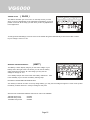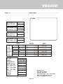
1
VG6000
This equipment has been tested in accordance with the
requirements contained in the appropriate Commission
regulations. To the best of our knowledge, these tests were
performed using measurement procedures consistent with
industry or Commission standards and demonstrate that the
equipment complies with the appropriate standards. Each
unit manufactured, imported or marketed, as defined in
the Commission's regulations, will conform to the sample(s)
tested within the variations that can be expected due to
quality production and testing on a statistical basis.
We further certify that the necessary measurements were
made by Kansai Electronic Industry Development Center,
Ikoma Emission Measurement Station, 10830, TakayamaCho, Ikoma-City, Nara, 630-01 Japan.
Page 1
VG6000
TABLE OF CONTENTS
Page #
2
3
4
5
6
7
8
9
10
11
12
13
14
15
16
17
18
19
20
21
22
23
Table of Contents
Radio Control System and Specifications
Academy of Model Aeronautics / Initial Preparation
Transmitter Features
Airborne System Connections / NiCd Charging Infomation
Airborne Components / Warning Alarms
Transmitter Battery Removal / Stick Length Adjustment
Transmitter Stick Tension Adjustment
Trainer System
Microprocessor / Bar Graph Voltage Indicator
Features Descriptions
Stick and Switch Functions
Dual Rates / Exponential
End Point Adjustment / Servo Centering
Servo Reversing / V-Tail Mixing
Delta Wing / Flaperons
Flaperons CONTINUED / Differential
Flap to Elevator Mixing / Aileron to Rudder Mixing
Model Select / Elevator to Flap Mixing
Throttle Cut / Count Down Timer
Sound Click / Battery Voltage Display
Model Settings
Page 2
VG6000
RADIO CONTROL SYSTEM
Thank you for selecting the Airtronics VG6000 Radio System. In designing the VG6000 we have
made every effort to provide you with a radio that will allow you to extract the maximum performance from your powered aircraft, or sailplane, while at the same time simplifying the task of
setting up and adjusting your model. These instructions are written in great detail to help you
understand what all of your VG6000 capabilities are. Flyers may find it advantageous to read all
sections of the manual to become more acquainted with the operation of the VG6000 system.
Again, we appreciate your selection of an Airtronics Radio Control System and wish you many
hours of flying enjoyment.
VG6000 Transmitter Specifications:
Transmitter Type:
Dimensions:
Weight:
Power Output:
Frequencies:
Modulation:
Power Supply:
Current Drain:
Temperature Range:
Pulse Width:
Model Memory:
6 Channel, Dual Stick with propriety Microprocessor.
W: 7.5” X H: 8.0” X D: 2.5”
1 lb. 11 oz
600 mWatts
72 MHz
PPM/FM Only
9.6 Volt, 700 mAh NiCd
180 MA
0 to160 degrees F
1.5 ms (nominal)
4
VG6000 Receiver Specifications:
Receiver Type:
Receiver Sensitivity:
Dimensions:
Weight:
Receiver Power Supply:
92777Z PPM/FM 7 Channel, Super Narrow Band with Universal “Z”
Connectors
1.5 microvolts
L: 2.20”, W: 0.06”, H: 0.82”
1.2 ounces
Four Cell, 4.8 Volt, 700 mAh NiCd
Additional Receivers that will work with the VG6000:
92515Z
5 channel FM Single Conversion receiver. (channels 11 thru 54 only)
Many older FM Airtronics receivers will work with the VG6000, check or call us to find out more.
Page 3
VG6000
ACADEMY OF MODEL AERONAUTICS
5161 East Memorial Drive
Muncie, Indiana 47302
The Academy of Model Aeronautics (AMA) is a national organization representing modelers in the United
States. We urge you to examine the benefits of membership, including liability protection in the event of
certain injuries. The Academy has adopted simple and sane rules which are especially pertinent for
radio controlled flight as the OFFICIAL AMA NATIONAL MODEL AIRCRAFT SAFETY CODE, which we have
partially reprinted below:
I will not fly my model aircraft in sanctioned events, airshows or model flying demonstrations until it has
been proven to be airworthy by having been previously, successfully flight tested.
I will not fly my model higher than approximately 400 feet within 3 miles of an airport without notifying the
airport operator. I will give the right-of-way and avoid flying in the proximity of full-scale aircraft. Where
necessary, an observer shall be utilized to supervise flying to avoid having models fly in the proximity of
full-scale aircraft.
Where established, I will abide by the safety rules for the flying site I use, and I will not willfully and
deliberately fly my models in a careless, reckless and/or dangerous manner.
I will have completed a successful radio equipment ground range check before the first flight of a new or
repaired model.
I will not fly my model aircraft in the presence of spectators until I become a qualified flyer, unless
assisted by and experienced helper.
I will perform my initial turn after take off away from the pit or spectator areas, unless beyond my control.
I will operate my model using only radio control frequencies currently allowed by the Federal Communications Commission. (See chart below) Only properly licensed amateurs are authorized to operate
equipment on amateur band frequencies.
72 MHz BAND by Channel and Channel Frequency
11
12
13
14
15
16
17
18
19
20
72.010
72.030
72.050
72.070
72.090
72.110
72.130
72.150
72.170
72.190
21
22
23
24
25
26
27
28
29
30
72.210
72.230
72.250
72.270
72.290
72.310
72.330
72.350
72.370
72.390
31
32
33
34
35
36
37
38
39
40
72.410
72.430
72.450
72.470
72.490
72.510
72.530
72.550
72.570
72.590
41
42
43
44
45
46
47
48
49
50
72.610
72.630
72.650
72.670
72.690
72.710
72.730
72.750
72.770
72.790
51
52
53
54
55
56
57
58
59
60
72.810
72.830
72.850
72.870
72.890
72.910
72.930
72.950
72.970
72.990
INITIAL PREPARATION
PACKAGING:
The packaging of your Airtronics VG6000 Radio Control System has been especially designed for the
safe transportation and storage of the radio’s components. After unpacking your radio, DO NOT DISCARD THE CONTAINERS! You should set the packaging aside for use if you ever need to send your
radio in for service, or to store your radio in case you do not plan to use it for an extended period of time.
Page 4
VG6000
VG6000 TRANSMITTERS FEATURES
The VG6000 narrow band PPM/FM computer radio control system is designed for the use of power
models and sailplanes for pilots who demand a quality product. The VG6000 is packed with all of the
capabilities that the beginner as well as the more advanced modelers demand. It has the features
available to get the most out of any type of model.
Program Features
Mixing Capabilities
Elevator and Aileron Dual Rates
Elevator and Aileron Exponential
End Point Adjustment all Channels
Servo Centering all Channels
Servo Reversing all Channels
4 Model Memory
Timer
Sound Click On/Off
Battery Voltage Display
Throttle Cut
Training System Compatable
V-Tail
Delta Wing
Flapewron
Aileron Differensial
Flap to Elevator Mixing
Aileron to Rudder Mixing
Elevator to Flap Mixing
Transmitter Features
Large LCD Display
One Menu Format Display
Digital Trim Display
Battery Voltage Bar Graph Display
Digital Trims
Low Battery Alarm
Throttle Cut Button
Trainer Button
Dual Rate Slide Switches
3 Position Flap Switch
2 Position Retract Switch
Smooth Movement Sticks
Oragomic Curved Case
Neck Strap Holder
Page 5
VG6000
AIRBORNE SYSTEM CONNECTIONS
NiCd Battery
Ch 6 Flap
Switch Harness
Ch 5 Gear
Ch 4 Rudder
Charge
Connector
Ch 3 Throttle
Ch 2 Aileron
BAND
92777/72 FM
Dual Conversion BY
Narrow Band Receiver
24
Ch 1 Elevator
7/B
6
5
4
3
2
1
92777Z Receiver
The above diagram shows how to connect the components of your VG6000 system together. At this point
your objective is to get the system operating on your workbench. Once connected you must then refer to
the corresponding diagram for your system showing the transmitter control stick function.
NiCd BATTERY CHARGING INFORMATION:
In order to protect the charging circuit in your VG6000 transmitter, a diode has been installed to protect it
from some of the high discharge rate “cycler’s” on the market. We recommend that you charge the
transmitter battery (while installed) with the supplied ATX charger, Part # 95033Z.
Should you wish to “cycle” or discharge the transmitter battery, you must first remove it from the transmitter. This allows you to bypass the protective diode.
The following two Airtronics service items will allow you to “cycle” your VG6000 transmitter battery. See
your local dealer for these items.
(1) #99704 Transmitter Charging Plug with Cable for use with your cycling device (black wire w/white
tracer is positive.
(1) #97051 Transmitter Battery Cycling Adapter Cable.
Above items will also work with Airtronics Quasar, Radiant, Vanguard, VG Series and all RD Series
transmitter batteries.
Page 6
VG6000
AIRBORNE COMPONENTS
While your systems batteries are charging, you can familiarize yourself with the airborne portion of your
radio. The airborne portion of the radio refers to any components which are mounted in your airplane and
carried aloft when you fly. The airborne components consist of the receiver, which receives the signals
from the transmitter, decodes them, and relays the commands to the servos. The servos which are
simply electronically controlled motors used to move the controls of the plane. The NiCd battery pack
which provides power for the receiver and servos to operate and the switch harness which allows you to
turn the airborne package on and off.
CONNECTORS
Your VG6000 unit is equipped the new universal AIRTRONICS “Z” connectors which are color coded
blue, and are electrically compatible with the receivers of other radio control system manufacturers. The
connectors are rugged but should be handled with care. Note that these connectors are not compatible
with older AIRTRONICS R/C equipment unless Adapter p/n 99399Z is used!
“Z” CONNECTOR
(-)Negative
(+)Positive
Signal
AUDIO LOW VOLTAGE ALARM
Your VG6000 transmitter is equipped with an Audio Alarm which will sound whenever the transmitter
batteries drop below 9.5 volts during transmitter operation. If the alarm sounds while you are flying, land
immediately and don’t operate the transmitter until it has been charged for 12 hours. The transmitter
should normally operate 120 to 150 minutes before the alarm sounds. If the alarm sounds even after the
batteries have been on charge for the required time it indicates that there is a problem with either the
battery pack or the transmitter, and you should contact AIRTRONICS about service.
THROTTLE HIGH WARNING
The VG6000 has a built in warning feature that will not allow you to use the transmitter if the throttle stick
is not in the lowest position when you turn on the transmitter. If the throttle stick is not in the low position,
when you turn it on, you will hear a continuous beeping sound and the display will read ( HI ). Pull the
throttle stick down to the full low position. The normal menu will then be displayed and you can operate
and/or program the transmitter.
Page 7
VG6000
TRANSMITTER BATTERY REMOVAL
The NiCd battery in your VG6000 transmitter can easily be removed and replaced with a fully charged
pack to extend operating time.
Additional packs are sold separately as an accessory item under the Airtronics part number 95010
(600Mah) or 95052 (1100Mah) battery packs.
To remove the pack, push down on the two ears of the battery door located on the rear of the transmitter.
The door can then be removed and the NiCd battery pack can now be removed and unplugged. Reverse
the procedure to install a new pack.
Negative
Positive
CAUTION:
Observe the correct polarity when plugging in the NiCd
battery pack. If incorrect, damage to the transmitter will
occur!
CONTROL STICK LENGTH ADJUSTMENT
The sticks in your VG6000 transmitter are adjustable in length and spring tension to allow you to tailor
their feel to your personal preference. To adjust stick length, hold Part B with your fingers and unscrew
Part A counterclockwise to loosen the two pieces. Now screw Part A in or out to the desired position and
lock it in place by screwing Part B against it. It is best to leave at least four threads inside Part A when
screwed out to its longest length for the best mechanical security. Do not over tighten when you screw
the two parts together.
Part (A) Loosen End Cap First
Part (B) Adjust Stick Length by turning here
Page 8
VG6000
TRANSMITTER STICK TENSION ADJUSTMENT
To adjust the spring tension of the transmitter sticks you need to remove the back of the transmitter case.
First remove the antenna and the NiCd battery pack from the transmitter. Now remove the eight screws
that hold the case back in place, four in the main case, two in the LCD back cover and two on the handle.
Once the screws are removed swing the back of the case away from the transmitter being careful of the
trainer plug wiring.
1
2
4
3
Screw Locations
There are four locations for the stick tension adjustment screws installed because the stick controlling
the throttle is ratcheted and has no tension adjustment. The #1 and #3 screws adjust the tension for the
vertical motion of each stick. The #2 and #4 screws adjust the tension for the horizontal motion of each
stick. To make the tension adjustment use a small phillips type screwdriver to turn the adjustment
screws. Turning the screw clockwise will increase the stick tension, turning it counterclockwise will
decrease the tension. Once you have completed your stick adjustments, replace the case back and
install the NiCd battery pack and antenna. Be careful to line the battery charging port pins when replacing
the back cover.
WARNING:
Any other modifications made to the transmitter other than adjusting stick tension will void any and all
warranties covered be Airtronics Inc.
Page 9
VG6000
TRAINER SYSTEM
The Trainer system in the VG6000 transmitter allows you to connect any two Airtronics RD series
transmitters together for the purpose of training a new pilot. You can also connect the VG6000 to either
VG 400, VG 600, Radiant or Vanguard PPM unit. The Trainer cord to use is the ATX Part # 97100.
The VG6000 is NOT compatible with Infinity 660 or Quasar units.
In actual use, one of the two transmitters will serve as the Master and the second transmitter will serve
as the Trainer. The Master transmitter is held by the instructing pilot, AND IS THE TRANSMITTER THAT
MUST MATCH THE RECEIVER FREQUENCY INSTALLED IN THE MODEL! The trainer transmitter is held
by the learning pilot, and does not need to be on the same frequency as the model. The frequency of the
Trainer transmitter is unimportant because the switch of the trainer transmitter is NOT turned on during
instructional flying. Normally during training, the instructor takes the model off and flies it to a reasonable
altitude. While the Master/Trainer switch on the Instructors transmitter is left in its OFF position, the
Master transmitter will have full control of the model. When the instructor is ready to begin training, he
presses and holds the spring loaded switch on his transmitter which transfers control to the student.
Master Transmitter
Trainer Transmitter
Trainer Switch
(Spring Loaded)
(As long as the instructor holds his Trainer switch in the ON position, the model will respond to the
commands of the Trainer transmitter sticks allowing the student to fly the model. It is not necessary for
the student to hold the trainer switch on the Trainer transmitter.)
When the instructor ceases to stop training, or if he feels that the student is in a situation that endangers the
model, the instructor can release the spring loaded switch and control of the model will immediately return
to the Master transmitter. To use the Trainer system, you must plug the appropriate Trainer cable into the
back of both the Master and the Trainer transmitters. Turn on the Master transmitter and the Model. The
cable will energize the encoder section of the Trainer transmitter. Once you have verified that both the Master
and the Trainer transmitters will control the model with the spring loaded switch in the appropriate position
you are ready to start training.
NOTE:
Both transmitters must be programmed identically for the trainer system to function properly. All servos
must operate in the same direction, centering, end points, and other settings such as type of Modulation
must be identical.
Page 10
VG6000
USING THE VG6000 MICROPROCESSOR
Airtronics has invested a large amount of design effort to ensure that the powerful capabilities of the
VG6000 are as simple as possible to use. This manual has been written to offer the user complete
instructions for fixed wing aircraft models. You only need to read the introduction section and the one that
applies to your type of model. In most cases all of the programming of a setup is accomplished through
the use of the input keys on the VG6000 transmitter. The function(s) of these are shown below.
Channel Selector and TImer
Moves Cursor to the Left
Moves Cursor to the Right
Decreases a value
Increases a valve
Note: Pressing the INC+ and DEC- keys simultaneously will clear a setting and return it to the default
value.
BAR GRAPH VOLTAGE INDICATOR
As a convenience the VG6000 transmitter provides a Bar Graph transmitter battery voltage indicator at the
right of the Liquid Crystal Display screen labeled “Empty” and “Full”. You can consider it similar to a
visible gas gauge. The Bar Graph indicator is in addition to the normal battery voltage that is displayed
on the screen when ever you select BATT. When the Bar Graph reads less than half you should not fly
until you recharge the transmitter.
Transmitter Battery Fuel Gauge
Page 11
VG6000
FEATURES DESCRIPTIONS
Screen Display
EL
Elevator Channel
AL
Aileron Channel
CH
Servo Channel 1~6
D/R
Dual Rate
EXP
Exponential
EPA
End Point Adjustment
CENT
Servo Centering
REV
Servo Reversing
V-TAIL
Rudder and Elevator Mixing
DELTA Elevons
FLPRN Flaperons
DIFF
Aileron Differential
FL-EL
Flap to Elevator Mixing
AL-RU
Aileron to Rudder Mixing
M-SEL Model Select 1~4
EL-FL
Elevator to Flap Mixing
T-CUT
Throttle Cut
TIMER Count Down Timer
CLICK
Click sound on or off
BATT
Battery Voltage
MODEL Current Selected Model
Page 12
VG6000
STICK AND SWITCH FUNCTIONS
LCD Display
Carrying Handle
Aileron Dual Rate
Dual Rate Elevator
CH 6 Flaps
CH 5 Retract
Trainer
Throttle Cut
N
1
2
RETRACT GE AR
EL FL
FL EL
2
2
TRAINER
1
DIGITAL MULTI FUNCTION DISPLAY
[ D/R EXP]
1
[ D/R EXP]
THROTTLE
CUT
High
LT
Down
RT
LT
Low
RT
Up
Throttle / Rudder
Stick
Aileron / Elevator
Stick
Power Switch
Crystal Cover
Front Panel
Page 13
VG6000
DUAL RATE AILERON AND ELEVATOR
( D/R )
This feature allows you to set a minimum and maximum control
rate for ailerons and elevator with the use of a dual rate switch.
Move the cursor to high-lite the EL D/R. By moving the Dual Rate
Elevator switch you can see the 1 and 2 turn off and on in
conjunction with the switch location 1 or 2.
Depending on how you like to use your dual rates will depend on the
switch direction you want the fast rate to be. For example you would
like to take off and fly on a lower rate with the switch in the #1 position
and for landing you want a faster rate on position #2.
First set the elevator dual rate switch to the #1 position. You can see on the screen that the percentage is 100. Use
the DEC- key to lower the number to about 75%. This will give you 25% less movement than the faster rate on position
#2 making position #1 your low rate and #2 your fast rate for landing. Repeat the same for Dual Rate Ailerons by
moving the cursor to the AL D/R.
Use the ( INC+ ) or the ( DEC- ) to raise or lower the percentages from 0 to 150%.
EXPONENTIAL ELEVATOR AND AILERON
( EXP )
Exponential allows you to change the amount of movement the
servo has compared to the stick movement. For example, when
you move the aileron stick left or right the servo will move at
the same rate as the stick when expo is set at 0. When flying
your aircraft with 0 expo, you will have the felling of 1 to 1 or a
linear fell. By increasing the expo to about 40% you will change
the amount of servo movement compared to the amount of stick
movement. When adding expo you will see that the servo will
move slower or less amount in the middle to 40% of your stick
movement. This will soften the fell of your ailerons around the middle area of the stick but will still give you full servo
movement at the end of the stick. Use the FUNCTION keys to move the cursor the EL EXP or AL EXP and press the
INC+ key to add expo.
A good starting point for aileron expo is +25% and use +5% for elevator.
Expo can be set for both switch positions 1 and 2.
NOTE: using Negative expo will make your ailerons and elevator more sensitive in the middle stick area which will
make the aircraft reactions very fast. Adjustment is from +100 to -100.
Page 14
VG6000
END POINT ADJUSTMENT (
EPA )
EPA will allow you to increase or decrease the total amount of travel the
servo has. EPA is available on all channels and should only be used to
fine tune maximum servo movement. All of your linkages and control
surfaces should be as close as possible to the model specifications
before decreasing or increasing EPA. A good example for EPA would
be when you want to use 2 aileron servos on 2 different channels and
you want to setup both to have the same amount of throws to each other
up and down. NOTE: You must have the FLAPERON feature activated in
order to use 2 sperate aileron servos.
To use EPA, move the cursor to the EPA using the FUNCTION keys. Next use the CH/TIMER key to change to the
channel you want to set your EPA. Next move the stick in the direction you want to increase or decrease and take
note the arrows on the LCD screen. They will point in the direction you are adjusting. EPA can be set independently
from side to side or up and down. Adjustment is from 0 to 150% in each direction.
SERVO CENTERING
( CENT )
Servo centering to a great feature when it comes to setting up a
new model and or setting your servo arms to right at 90 degrees.
When using servo centering, take note that it will change not only
the center position of the servo but as well change both left and
right end points.
Example, you installed a servo arm on your servo but it will not
lineup perfectly 90% to the servo. You now can adjust the servo
centering so now the arm is at 90% of the servo. Servo centering
can be adjusted from 0 to 100% but is best kept within + or - 10%
any more than that you will need to try another servo arm or adjust
your linkage better.
To use CENT, move the cursor to the CENT using the FUNCTION keys. Next use the CH/TIMER key to change to the
channel you want to set your CENT. Adjust using the INC+ or DEC- keys. Adjustment is from +100 to -100.
Page 15
VG6000
SERVO REVERSING
( REV )
After setting up your aircraft you find that the control surface is
moving in the wrong direction, you can use the REV to reverse
the direction that the servo operates. REV is available on all channels.
To use REV, move the cursor to the REV using the FUNCTION keys. Next use the CH/TIMER key to change to the
channel you want to change the REV. Next press either the INC+ or DEC- to change from NOR to REV.
V-TAIL MIXING
( V-TAIL )
If you have a V-tail aircraft, you will need to activate this feature.
After activating V-Tail you will need to first connect the left V-tail to
channel 1 and the right V-Tail to channel 4. Next check the directions
on both servos making sure they operate in the correct directions. If
either one does not work in the correct direction you will need to use
REV for that channel. See REV for more details.
You can use both channel 1 and 4 ( CENT, EPA and REV) to correctly
setup your V-Tail.
To use V-Tail, move the cursor to the V-Tail using the FUNCTION keys. Next use the INC+ or DEC- keys to change from
V-Tail OFF to ON.
NOTE: use channel 1 for the left V-Tail and channel 4 for the right V-Tail.
Left CH 1
Right CH 4
Page 16
VG6000
DELTA WING
( DELTA )
The Delta feature is used when your aircraft is a flying wing.
You will use two servos on two seprate channels to mix both
ailerons and elevator together using only the left and right wing
controls. You will use channel 1 for the left wing and channel 2
for the right wing. Mount the servos as shown in the drawing
below. After you have installed the servos check to make sure
that the ailerons work in the proper direction and check that when
you move the elevator, both ailerons move up and down in the
proper direction. If eighter channel is not working in the corect
direction simply change the direction of the servo using the REV
for that channel.
To use DELTA, move the cursor to the DELTA using the FUNCTION keys. Next use the INC+ or DEC- keys to select YES
or NO. Selecting YES will activate DELTA on.
Delta Wing Setup
Lt Wing Channel
FLAPERONS
1
Rt Wing Channel
2
( FLPRN )
Flaperons are used when you want to have both your ailerons work as
flaps as well. For this to work you will need to setup two aileron servos
on two sperate channels on a conventional aircraft. You will be using
Channel 2 for the left aileron and channel 6 for the right aileron.
Before installing the linkage to the servos make sure that your flap
switch CH 6, is in the proper “N” position. This will make sure that when
you turn on or activate the flaperons, your servos will not change there
centering. Remember! if you activate or turn on Flaperons, both servos
should not move. If they do, you do not have the flap switch in the proper
position. Next make sure both ailerons are working in the proper direction. If not use the REV to correct.
After your ailerons are working properly, move the flap switch “CH 6” to the middle or position 1. Both ailerons should
move down to there 50% flaps down position. Next move the flap switch to position 2. This will move both ailerons
down to there 100% down position. Remember both flap positions are adjustable.
To use FLPRN, move the cursor to the FLPRN using the FUNCTION keys. Next use the INC+ or DEC- keys to change to
turn flaperons on of off. See next page for servo setup.
Other features that work together with flaperons: (DIFF), (FL-EL), (EL-FL), (Flaps ch 6)
Page 17
VG6000
FLAPERONS
( FLPRN )
CONTINUED
Lt Wing Channel
2
Rt Wing Channel
6
Flaperon setup
DIFFERENTIAL
( DIFF )
By turning on your flaperon feature you can now use differential.
What differential does is actually change the amount of aileron
movement percentage between the aileron being in the up position
compared to the down position.
Example: If you had a Piper Cub for an aircraft, you would know
that it really does not roll very well. With the use of some
differential however, you can make the Cub roll much better. To do
this you will need to have your ailerons actually have more up
movement than down movement killing more lift than creating lift
because a Piper Cub generates a lot of lift with its wing design.
This feature is a most for any sailplane flier.
To use DIFF, move the cursor to the DIFF using the FUNCTION keys. Next use the INC+ or DEC- keys to change the
percentages from 0 to + or - 100%. Depending on your aircraft typically you will want the ailerons to have more up
movement than down when operating your ailerons. This works well for aircraft that has a flat or semi symmetrical
air foil.
Other features that work together with differential: (FLPRN), (FL-EL), (EL-FL), (Flaps ch 6)
DIFF will not work with Delta and will only work if FLAPRN is activated.
Page 18
VG6000
FLAP TO ELEVATOR MIXING
( FL-EL )
When you lower your flaps on just about any aircraft, it will tend to
raise the nose or start to climb. By using the Flap to Elevator mix,
you can change the way the aircraft reacts when the flaps are
lowered by adding a small amount of down elevator. Flaps are
mainly used to create more lift so the aircraft can land at a slower speed.
To use FL-EL, move the cursor to the FL-EL using the FUNCTION keys. Next use the INC+ or DEC- keys to change the
percentage of up or down elevator as needed. To see the amount of elevator movement you must move the flap
switch to position 1 or 2. When the flap switch is in the “N” normal position, you will not see any flap to elevator
mixing. Default is set at 0. Range is from -100 to 100% and 0 is no elevator mix at all.
AILERON TO RUDDER MIXING
( AL-RU )
On some high wing aircraft that have a lot of side area on the
fuselage will find that aileron to rudder mixing will greatly help
when making a turn. The way this mix works is as you move the
aileron stick left or right, the rudder will move as well giving you
a little more control on your turns. Always have the rudder move
in the same direction as the aileron. You may want to start with
a small amount of mix to start with and adjust as needed after a flight.
Remember: when setting a aileron to rudder mix, it will be active at all
times You do not have a switch to turn it off.
To use AL-RU mixing, move the cursor to the AL-RU using the FUNCTION keys. Next use the INC+ or DEC- keys to
change percentage of rudder movement.
Page 19
VG6000
MODEL SELECT
( M-SEL )
The VG6000 computer radio system comes with 4 model memory. This
allows you to have 4 completely separate models using one transmitter.
To change models, move the cursor to the M-SEL using the FUNCTION keys. Next use the INC+ or DEC- keys to select
models 1~4.
All settings are saved automatically on all models. All trims, mixes, servo directions, etc. are saved as you set them.
The VG6000 will not lose any memory even if you were to remove the main battery. All your setting are saved in a
eprom chip that does not need any type of battery to hold its memory.
ELEVATOR TO FLAP MIXING
( EL-FL )
Elevator to flap mixing can be used in several aircraft. Sailplanes
like this feature when they are making a turn it will drop the flaps
slightly to help generate a little more lift. Power aircraft will benefit
this when making landing approaches and when flaring the
aircraft just before touch down. Adding flaps as needed on landings
will help out any landing.
To use EL-FL mixing, move the cursor to the EL-FL using the FUNCTION keys. Next use the INC+ or DEC- keys to
change percentage of flap movement.
Elevator to Flap mixing will also work if Flaperons are activated. Default is “0” settings are from 100 to -100.
Page 20
VG6000
THROTTLE CUT
( T-CUT )
After you have landed and taxied back, you can shoot your engine off
by simply pushing a button. The throttle cut feature will do just that.
To set you throttle cut first you must make sure the throttle is working
properly and it will come to a low idle. No more need to use the trim
to shoot your engine off.
To use T-CUT, move the cursor to the T-CUT using the FUNCTION keys. Next use the INC+ or DEC- keys to change the
percentage of throttle cut needed. Throttle cut only works when the stick is in the low position. Make sure the throttle
barrel on your engine will go below the lowest idle position before adjusting throttle cut. Default is “0” setting are from
15 to -15
COUNT DOWN TIMER
( TIMER )
Count down timers help to remind you that it’s time to land meaning lets
get it down before we run out of fuel. If you know how long a normal
flight is on your aircraft “example” 15:00 minutes, you can set the down
timer to sound off at 13:00 minutes. This will give you approximately
2:00 minutes to land with some fuel left over in-case you need to do a
go around. Timer can be set from 0 to 60:00 minutes and are set in
10 seconds intervals.
Example: the left two nubers represent 0~60 minutes and the number
on the right represent 10th’s. 10, 20, 30, 40, 50.
After the timer has reached “0”, it will start to count up. At every minute you will hear 2 beeps.
To set the timer first move the cursor to TIMER using the FUNCTION keys. Number will be flashing 00’0. Use the INC+
key to set the amount of time. Example: timer reads 01’3, this will give you a count down 1 minute 30 seconds.
Pressing the CH/TIMER button will start the count down timer. At the end of the count down you will hear a seies of
beeps starting at the last 10 seconds of the count down.
To stop the timer at anytime simply push the CH/TIMER button. To restart push it again.
To reset the timer simply press both INC+ and DEC- at the same time.
To reset the timer to 00’0 simply press both INC+ and DEC- again. ( 2 times )
Page 21
VG6000
SOUND CLICK
( CLICK )
This feature will allow you to turn off or on the beep sound you hear
when you do any adjustments to the transmitter programming. In the off
position it will turn off the beep you hear when you do any adjustments
to the digital trims.
To change the CLICK settings, move the cursor to the CLICK using the FUNCTION keys. Next use the INC+ or DECkeys to change it from on to off.
BATTERY VOLTAGE DISPLAY
( BATT )
The Battery numeric display will give you the exact voltage of your
battery and to the right of the LCD screen you can see the battery
graph showing full to empty. At a full charge you may see the
voltage be as high as 11.4.
A low battery beeper with sound when the battery reatches 9.1 volts.
Land emediatly if you hear the low battery warning beep.
DO NOT FLY IF BATTERY VOLTAGE IS LOW.
Your battery is rated at 9.6 volts. On a fully charge battery, you may see the voltage as high as 11.4 but never fly after
the battery reatches below 9.5. Always recharge at this point.
AIrtronics has 3 transmitter batteries that can be used in the VG6000
700 MAh Sport Pack
600 MAh Sanyo Pack
1100 MAh Sanyo Pack
# 95090
# 95010
# 95052
Page 22
VG6000
MODEL #........................................................................MODEL NAME....................................................................................
NOTES:
EL D/R (1)
EL D/R (2)
%
EL Expo (1)
EL Expo (2)
%
AL D/R (1)
AL D/R (2)
%
AL Expo (1)
AL Expo (2)
%
%
%
%
%
EPA
1 EL
2 AL
3 TH
4 RU
5G
6 FL
V-Tail
Delta
Flaperons
Differential
FL - EL Mix
AL - RU Mix
EL - FL Mix
T-Cut
Timer
Click
CENT
REV
%
%
%
NOR / REV
%
%
%
NOR / REV
%
%
%
NOR / REV
%
%
%
NOR / REV
%
%
%
NOR / REV
%
%
%
NOR / REV
OFF / ON
OFF / ON
OFF / ON
%
%
%
%
Airtronics Inc
1185 Stanford Court
Anaheim, CA 92805
PH: 714-978-1895 FAX: 714-978-1540
Web Site: www.Airtronics.net
e-mail: [email protected]
%
min
sec
OFF / ON
Page 23